1. Introduction
Phage therapy is the application of a bacteria-specific virus to treat pathogenic bacterial infections. This therapy has many potential applications in human medicine as well as veterinary science, agriculture, and food processing. The discovery of bacteriophages is controversial since different claims have been formulated [
1,
2,
3]. Nevertheless, it is recognized that d’Herelle performed the pioneering work and proposed the name of bacteriophages for viruses capable of invading bacterial cells and disrupting bacterial metabolism, causing bacterial lysis. Basically, bacteriophages undergo a lytic cycle through which they self-replicate and lyse a broad variety of bacterial strains.
Specifically, bacteriophages appear highly interesting as a relatively cost-effective antibiotic alternative to treat bacterial infections that have developed antibiotic resistance. Bacteriophages also appear highly interesting when biofilms resistant to antibiotic penetration (e.g., those covered by a polysaccharide layer) were produced. The high specificity of bacteriophages toward both Gram-positive and Gram-negative bacteria is also attractive since they are seen to be harmless to the host organism as well as to beneficial bacteria (e.g., gastrointestinal flora). Nowadays, bacteriophages have been revealed to be highly appropriate for the treatment of poorly-healing wounds, e.g., in diabetic and bedridden patients as well as those affected by venous stasis ulcers [
4,
5]. The treatment has greater costs since liquid preparations of phages are applied locally, requiring a frequent change of dressings. Therefore, recent approaches deal with the incorporation/encapsulation of phages into a polymeric matrix or their immobilization onto a polymeric surface.
Biodegradable poly(ester amide)s based on amino acids have been employed as matrices for the deposition of a combination of phages with other medicaments. The product has been commercialized under the trademark of PhagoBioDerm, being beneficial for the treatment of chronic wounds [
6] and multidrug-resistant
Staphylococcus aureus infections [
7]. Bacteriophages have also been revealed to be effective in the treatment of
Pseudomonas aeruginosa [
8,
9,
10,
11], which is probably the microorganism responsible for the most common infections in hospital environments [
12]. These infections tend toward chronicity, with a mortality rate of up to 61%, since infections cannot be effectively treated with any antibiotic combination [
13].
Escherichia coli is also a common multidrug-resistant Gram-negative bacterium that is able to spread, rapidly causing sepsis with a high mortality rate [
14]. The infection of
E. coli by the bacteriophage T4 is highly effective and has been one of the most studied model systems in microbiology [
14,
15]. Encapsulation of phages in microspheres by means of an emulsion-solvent extraction method has also been performed, but results showed a loss of activity that was attributed to the organic solvent employed [
16]. Creation of antimicrobial surfaces by passive immobilization [
17], through chemical bioconjugation [
18], covalent anchoring [
19], or by electrostatic interactions, taking advantage of the different charge distribution between head and tail [
20], has also been assayed, with differing levels of success. Logically covalent attachment was revealed to be more effective than simple electrostatic binding since bacteriophage detachment could be decreased [
21]. Though PhagoBioDerm showed remarkable wound healing potential, it represents a film material (“artificial skin”) that is rather rough and irritating to wounds, especially for large wounds and burns; to allow the wound exudate to freely come out and the wound surface to breathe, the PhagoBioDerm film is perforated using special equipment. Therefore, it is desirable to produce soft and nonwoven porous wound dressings, which can provide both free exudate evacuation and wound breathing. Such materials can be obtained via the electrospinning technique.
Electrospinning is currently an easy process to create micro/nanofibers and mats with a tunable porosity after the accumulation of fibers. An additional advantage of the technique is the great versatility that allows for working with a great variability of polymeric materials and loading different active agents for the required application (e.g., the preparation of scaffolds with bactericidal properties). Basically, a high electrical field is applied to a liquid droplet held at the end of a capillary tube. The drop becomes electrically charged and stretched when the electrostatic repulsion counteracts the surface tension. In this way, a jet is ejected towards a grounded target (collector) [
22,
23,
24]. Solution characteristics (e.g., solvent, polymer concentration, conductivity, vapor diffusivity) and operational parameters (e.g., distance between the needle to the collector, flow rate, and applied voltage) can easily be modified in order to get continuous and homogeneous fibers with the desired morphology. Great efforts are nowadays focused on overcoming one of the main limitations of the technique: its scalability for industrial production. Many technological solutions have already been proposed to allow large-scale production as reviewed by Persano and collaborators [
25].
Electrospun scaffolds have good characteristics of wound dressings: porosity, permeability, flexibility, and the ability to deliver antimicrobial agents through the selection of the appropriate polymer matrix [
26].
Scarce works have focused on the encapsulation of phages by the electrospinning technique. In this way, water-soluble polymers like polyvinyl pyrrolidone (PVP) [
27,
28], polyvinyl alcohol (PVA) [
29], and poly(ethylene oxide)/cellulose diacetate [
30,
31] have been assayed for M13, T4, T7, and
λ bacteriophages, with results not being completely satisfactory due to a significant loss of activity that was attributed to phage dehydration and solvent evaporation during the electrospinning process. The addition of excipients such as sodium chloride, magnesium sulfate, or sucrose was reported to avoid the damaging effect of dehydration and maintain a high level of bacteriophage infectivity after electrospinning. In fact, these excipients were able to provide protection over storage and mitigate environmental effects on the dried samples [
32]. Bacteriophage T4 has also been effectively incorporated into poly(
ε-caprolactone)/collagen (30%/70%
w/
w) electrospun fibers to eradicate
E. coli infections (i.e., the inhibition efficiency of
E. coli activity around 90%) while establishing hemostasis [
15]. An organic 1,1,1,3,3,3-hexafluoroisopropal solution was employed in this case to perform the electrospinning process. Emulsion and coaxial electrospinning processes have also been considered in order to overcome the problems associated with the sensitivity of bacteriophages. In this way, good results were achieved by allocating bacteriophages into the core of a core/shell fiber protective structure [
30]. Finally, it should be pointed out efforts focused on immobilizing bacteriophages onto the surface of electrospun scaffolds. Thus the vB_Pae_Kakheti25 bacteriophage, which is highly effective against
P. aeruginosa, was covalently immobilized through the formation of amide linkages onto PCL electrospun nanofibers. Materials with immediate and complete bacterial reduction were reported [
8].
In order to evaluate the possibility of encapsulating bacteriophages into scaffolds constituted of electrospun nanofibers, we have considered it necessary to structure the present work in three different steps: (a) Evaluation of the effect of electric field on the activity of bacteriophages, (b) evaluation of the bactericide activity from electrospun scaffolds prepared using an aqueous media and avoiding a pre-lyophilization step, and (c) evaluation of the viability of bacteriophages when the electrospun fiber matrix consists on a water-insoluble polymer. This matrix can avoid the prompt phage delivery that is expected when the scaffold becomes in contact with an aqueous medium capable of solubilizing the polymer.
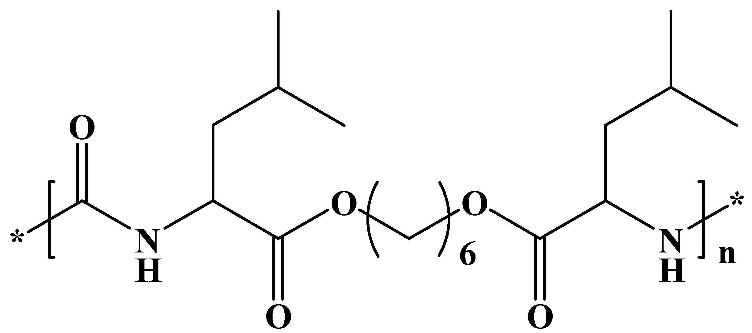
We have selected a leucine-based poly(ester urea) (PEU) (
Figure 1) since
α-amino acid-based polymers are receiving great attention as new biodegradable materials for biomedical applications due to their favorable combination of properties [
33,
34]. High-molecular-weight PEUs with desirable material properties are being used, for example, as implantable surgical devices and can be easily synthesized via interfacial polycondensation [
35]. Specifically, a derivative of L-leucine, carbonic acid, and 1,6-hexanediol (named PEU 1L6) has been selected. The polymer is characterized by a melting temperature of 114 °C, a glass transition temperature of 47 °C, and a tensile strength at yield, elongation at break, and Young’s modulus of 21 MPa, 114%, and 622 MPa, respectively. Previous works indicated that the polymer could be electrospun into micro/nanofibers loaded with antibacterial drugs [
36]. Furthermore, hybrid electrospun scaffolds constituted of a mixture poly(3-thiophene methyl acetate) and a copolymer based on 1L6 showed promising conductive and biodegradable properties [
37].
2. Materials and Methods
2.1. Materials
All chemicals were of ACS grade and used without further purification. The selected PEU was prepared by interfacial polymerization, as previously described (
Figure S1) [
36]. Specifically, di-
p-toluenesulfonic acid salt of bis-
l-leucinehexane-1,6-diester (L6) was reacted with triphosgene. The average molecular weight and polydispersity index were 70,000 g/mol and 1.4, respectively.
Figures S2–S6 report basic characterization and enzymatic degradation data concerning 1L6 films and electrospun scaffolds [
35]. Poly(ethylene glycol) (PEG) with an average molecular weight of 35,000 g/mol, was purchased from Sigma-Aldrich. Pharmaceutical-grade calcium carbonate (mean particle size 6.20 ± 0.013 µm) was kindly provided by JSC Biochimpharm, Tbilisi, Georgia. The particles’ size was assessed in a water suspension using laser particle size analyzer LS-C(III) (OMEC Instruments Co., Ltd., Zhuhai, China).
Fersis bacteriophage is a sterile filtrate of phage lysates of
Staphylococci (
S. aureus and
S. epidermidis) and
Streptococci (
S. pyogenes, S. sanguis, S. salivarius and
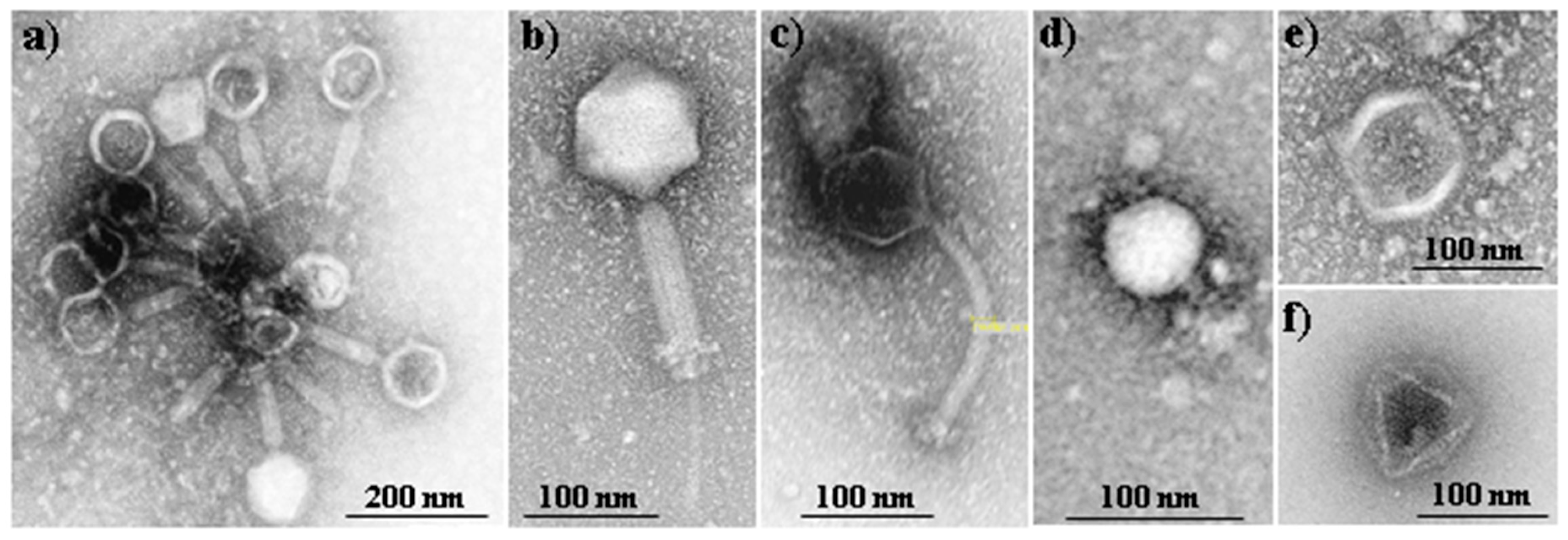
S. agalactiae), being commercially employed in therapeutic and prophylactic purposes in pyo-inflammatory and enteric infections caused by the above mentioned microorganisms. Fersis bacteriophages have a typical morphology with well-defined capsid and tail parts (
Figure 2a). The preparation was provided by the G. Eliava Institute of Bacteriophages, Microbiology and Virology of Georgia.
Phagestaph consists of a cocktail of bacteriophages that exhibit different morphologies, as shown in
Figure 2b–f. The product is also commercially available and has been designed with specific action against
Staphylococcus aureus. Phagestaph bacteriophages were purchased from JSC Biochimpharm, Tbilisi, Georgia.
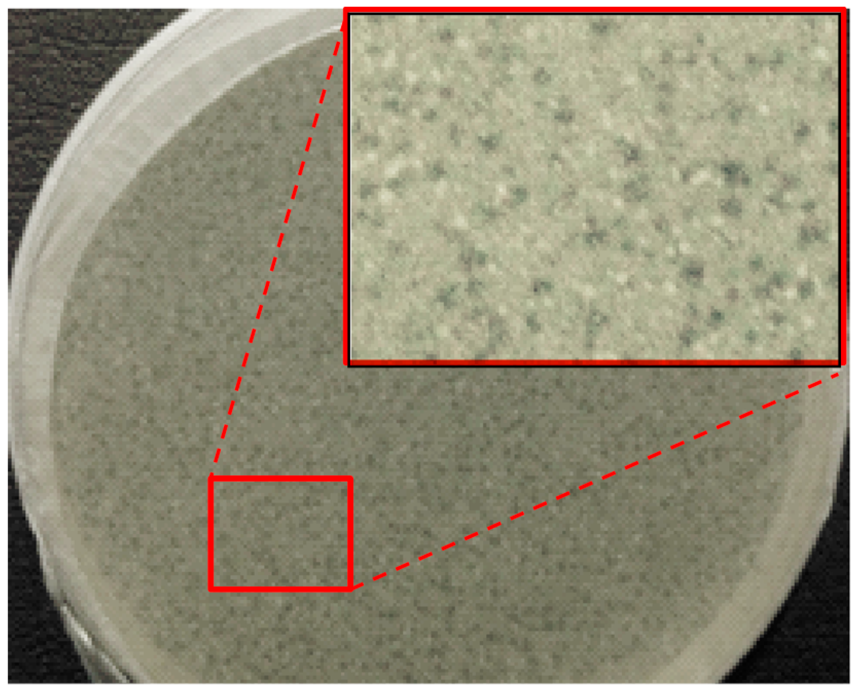
Adsorption of phage on calcium carbonate particles was done according to [
24]. Typically, 300 mL of liquid bacteriophage were added to 30 g of powdered CaCO
3 at room temperature (i.e., a 1:10
w/
v dispersion was obtained). The mixture was thoroughly homogenized by stirring for 20 min. The mixture was subsequently kept at room temperature for an additional 30 min without agitation. The precipitated solid was filtered off and dried in a vacuum at 40–45 °C over a water-adsorbent substance (anhydrous Na
2SO
4 or silica gel). After such treatment, a significant portion of the water-soluble salts and organic admixtures of the initial phage solution was removed [
38].
The microbial culture was prepared with reagents and labware from Scharlab (Spain). Staphylococcus aureus (S. aureus) ATCC 25923 (American Type Culture Collection, Manassas, VA, USA) Epithelial-like (Vero) cells (ATCC, Manassas, VA, USA) were used in this work for cell adhesion and proliferation studies.
2.2. Measurements
Molecular weight was estimated by gel permeation chromatography (GPC) using a liquid chromatograph (Shimadzu, model LC-20AD, Kyoto, Japan) equipped with a LC solution GPC software (Shimadzu). The number and weight average molecular weights and molar-mass dispersities were calculated using poly(methyl methacrylate) standards.
Contact angles (CA) were determined at room temperature with sessile drops using an OCA-15 plus Contact Angle Microscope (Data-Physics Instruments GmbH, Filderstadt, Germany) and SCA20 software. Contact angle values of the right and left sides of distilled water drops were measured and averaged. Measurements were performed 10 s after the drop (0.5 µL) was deposited on the sample surface. All CA data were an average of six measurements on different surface locations.
A Philips TECNAI 10 electron microscope was used and operated at 100 kV for observation of the morphology of bacteriophages. A Shimadzu 3600 spectrometer was employed for absorbance measurements.
2.3. Electrospinning
Electrospun fibers were collected on a target placed at different distances (10–25 cm) from the needle tip (inside diameter of 0.84 mm). The voltage was varied between 10 and 30 kV and applied to the target using a high-voltage supply (Gamma High Voltage Research, ES30-5W). Polymer solutions were delivered via a KDS100 infusion syringe pump (KD Scientific, Holliston, MA, USA) to control the mass-flow rate (from 0.5 to 5 mL∙h−1). All electrospinning experiments were carried out at room temperature. Electrospun fiber scaffolds were prepared using optimized parameters (i.e., needle tip–collector distance, voltage and flow rate) and solvent conditions (i.e., solvent ratio and polymer concentrations).
Electrospinning of PEG was carried out using the commercial Phagestaph solution (F), a 1:1 dilution of Phagestaph with water (WF) and water alone (W).
Electrospinning of PEU was performed in an chloroform:ethanol (10:1 v/v) mixture. Bacteriohages were incorporated by addition of the lyophilizate of the provided Phagestaph or Fersis preparations. Alternatively, calcium carbonate particles with bacteriophages adsorbed on their surface were added to the electrospinning solution. In this case, salts and organic residues of the initial solution could be avoided.
2.4. Morphology of Electrospun Scaffolds
Optical microscopy studies were performed with a Zeiss Axioskop 40 microscope. Micrographs were taken with a Zeiss AxiosCam MRC5 digital camera. Detailed inspection of texture and morphology of electrospun samples was conducted by scanning electron microscopy using a Focus Ion Beam Zeiss Neon 40 instrument (Carl Zeiss, Oberkochen, Germany). Carbon coating was accomplished using a Mitec K950 Sputter Coater fitted with a film thickness monitor k150×. Samples were visualized at an accelerating voltage of 5 kV. Diameters of electrospun fibers were measured with the SmartTiff software from Carl Zeiss SMT Ltd., Oberkochen, Germany.
2.5. Bacterial Growth
S. aureus bacterium was selected to evaluate the antimicrobial effect of electrospun 1L6 scaffolds loaded with the selected bacteriophages. The bacteria were previously aerobically grown to exponential phase in broth culture (brain heart infusion medium, BHI). Growth experiments were performed in polystyrene tubes using 5 mL of broth. Square pieces (10 mm × 10 mm) of the electrospun scaffold with a thickness of 0.1 mm were place into each tube. Then, 1 mL of broth culture containing 103 culture forming units (CFU) was seeded on the electrospun fiber mats. The cultures were incubated at 37 °C and agitated at 200 rpm. Aliquots of 100 µL were taken at predetermined time intervals for absorbance measurement at 650 nm in a plate reader. Thus, turbidity was directly related to bacterial growth. All assays were conducted in triplicate and the values averaged.
2.6. Virus Plaque Assay
Bacteriophages were quantified by means of the double agar method, which allowed for determining circular zones of bacterial lysis (named plaque) caused by the phage action. To this end, a small volume of a dilution of phage suspension (100 µL) and host cells (200 µL of a bacterial culture with A600 = 0.3) were mixed for 20–30 min at 37 °C and 80 rpm. Then, 3 mL of BHI soft agar (7% agar) was added, mixed in molten state, and subsequently poured onto an appropriate BHI agar medium (15% agar). A thin layer was formed and let to harden in order to immobilize bacteria (i.e., the virus could only infect contiguous cells). The uninfected bacteria multiplied during incubation to form a confluent lawn of bacterial growth over the surface of the plate. Each infected bacterium burst after a short time and liberated progeny bacteriophages that infect adjacent bacteria, which in turn were lysed. This chain reaction spread in a cycled motion until led to a halt by a decline in bacterial metabolism. Phage activity was evaluated by counting plaques (i.e., halts) and quantified as plaque-forming units per mL (PFU/mL).
2.7. Cell Adhesion and Proliferation Assays
Adhesion and proliferation tests were performed as a measure of the biocompatibility of the 1L6 scaffolds loaded with bacteriophages. Vero cells were cultured in Dulbecco’s modified Eagle medium (DMEM), as previously reported [
39]. Unloaded and bacteriophage-loaded PEU 1L6 scaffolds (pieces of 1 cm × 1 cm) were placed into the wells of a 24-well culture plate. Samples were fixed in the wells with a small drop of silicone (Silbione
® MED ADH 4300 RTV, Bluestar Silicones France SAS, Lyon, France) and then sterilized by UV-radiation in a laminar flux cabinet for 15 min. For the cell adhesion assay, aliquots of 50–100 µL containing 5 × 10
4 cells were seeded onto the electrospun samples in each well and incubated for 24 h for adhesion assay, while 2 × 10
4 cells were cultured by 72 h for the proliferation assay.
The cellular viability was evaluated by the standard method of MTT using five replicates and the results were averaged. Samples with adhered and grown cells on the mats were fixed with 2.5% w/v of glutaraldehyde at 4 °C overnight. They were subsequently dehydrated and processed for observation by scanning electronic microscopy.
2.8. Statistical Analysis
Values were averaged and graphically represented, together with their respective standard deviations. Statistical analysis was performed by one-way ANOVA test to compare the means of all groups, and then Tukey’s test was applied to determine a statistically significant difference between the two groups. The test confidence level was set at 95% (p < 0.05).
3. Results
3.1. Effect of the Electrical Field on the Morphology and Activity of Bacteriophages
It has been evaluated the value of the electrical potential,
V, along the cylindrical geometry of the electrospinning process using a homemade program and considering a constant dielectric permittivity,
ε, and a null value for the charge density
ρv. Namely, the effect derived from the small amount of solvent in the process was considered negligible. Under these approximations, the typical Poisson equation (Equation (1)) that defines the electrical potential generated by regions with a fixed potential becomes the Laplace equation (Equations (2) and (3) when the divergence operator, ∇, is expressed in cylindrical coordinates). The relation between the electric potential and the electric field,
E, is defined by Equations (4) and (5).
where
ρ,
φ, and
z indicate the radial, azimuthal, and axial directions, respectively.
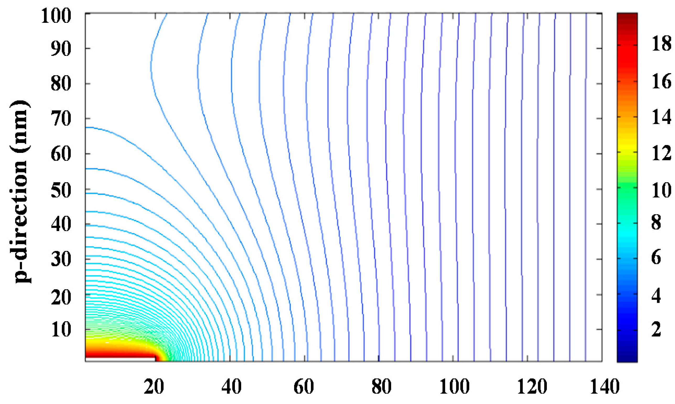
The problem can be simplified to two dimensions considering the azimuthal symmetry of the process. Resolution of the bidimensional equation requires an iterative process since the integration region requires to be defined by fixed conditions, which a priori are only known for the planar collector surface and the needle tip. The iterative successive over-relaxation (SOR) method was applied to solve Equation (3) and specifically
Figure 3 and
Figure S7 show the equipotential lines and the modulus of the electrical field that were determined for an applied voltage of 30 kV. The maximum value of the electrical field was logically found at the needle tip and corresponded to a value of 40 kV∙cm
−1.
In order to evaluate the effect of the field on the activity of bacteriophages we centered the attention on the time that the electrospun solution was located close to the needle due to the non-homogeneous shape of the electrical field, The ratio between the volume of the Taylor cone and the flow rate,
φ, allows estimating the time,
πe, at which the solution was under the maximum electrical field:
where
Rcon and
hcon are the radius (equivalent to the radius of the needle) and the height of the cone, respectively.
The equation indicates that πe becomes 5 min for the minimum assayed flow rate of 0.1 mL/h and an overestimated cone height of 3.2 cm.
In order to see the effect of the electric field on the phage activity, the commercial Phagestaph preparation was deposited without any previous treatment (e.g., dilution or lyophilization) in a parallel plane capacitor. The maximum electric field at which bacteriophages should be exposed during electrospinning (i.e., 40 kV/cm) was applied for
πe values of 0.1 and 5 min. The bacteriophage activity was evaluated by the double agar method (
Figure 4) and compared with the activity attained with the commercial preparation. The studies were performed in triplicate and showed that the activity was not modified by the effect of the field. Specifically, values of 5.0 × 10
3 ± 0.8 × 10
3 PFU/mL, 6.5 × 10
3 ± 0.5 × 10
3 PFU/mL and 5.5 × 10
3 ± 0.6 × 10
3 FPU/mL were determined for the control and after exposition for 0.1 min and 5 min, respectively. Transmission electron micrographs showed also that morphology remained unaltered, being well defined capsids with diameters around 60–100 nm clearly detected as well as ca. 250 nm long tails in the case of
Myoviridae and
Siphoviridae species (
Figure S8).
3.2. Electrospinning of PEG Loaded with Bacteriophages
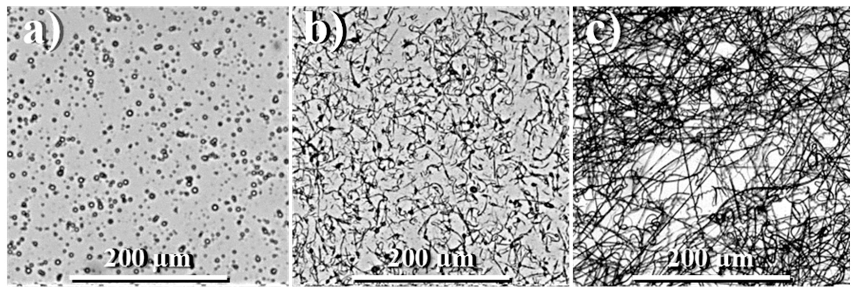
Electrospinning of PEG samples was initially performed using water (W) as solvent and high polymer concentration due to the low molecular weight of the polymer. A series of experiments at concentrations of 37%, 47%, 50% and 53 wt % were carried out, being representative electrospun fibers attained under typical conditions shown in
Figure 5.
The concentration of 50 wt % was selected for further experiments since it was found to be the minimum necessary to get continuous fibers and avoid the formation of droplets. Two different media were selected in order to perform the electrospinning of PEG loaded with Phagestaph: the direct commercial Phagestaph preparation (F) and its dilution with 50 v % of water (WF).
The viscosity and surface tension of the F, WF, and W media were similar (i.e., differences were lower than 1%) but great changes were logically detected on their electrical conductivity and salt content. Thus, conductivities of 20, 213, and 374 mS/cm were determined for W, WF, and F solutions, respectively, whereas the content of salts was 0, 0.1, and 0.2 ppt (‰).
For the optimization of the electrospinning process the applied voltage, the flow rate and the needle collector distance were varied between 20–30 kV, 0.1–5 mL/h and 8–15 cm, respectively. We selected the maximum flow rate, minimum voltage, and maximum distance that allowed for forming a Taylor cone and get homogeneous and continuous fibers, while the formation of beads and droplets was avoided. Basically, selected conditions tried to minimize the electric field at which bacteriophages were exposed and the time required to get a homogeneous scaffold.
Table 1 summarizes the optimal conditions determined for each solution. The most significant variation concerns the flow rate, which became minimal when the more conductive F solution was employed (i.e., 0.1 mL/h with respect to the 5 mL/h that was necessary for the aqueous solution). The time,
πe, at which bacteriophages were exposed to the maximum electric field also increased with the conductivity of the solution. A needle-collector distance of 12 cm allowed us to guarantee the complete evaporation of water and was selected for all systems since it allowed for fibers with diameters in the appropriate range (i.e., between 620 and 818 nm). In other words, it was not considered necessary to increase the distance for the W medium in order to compensate for the effect of its lower conductivity.
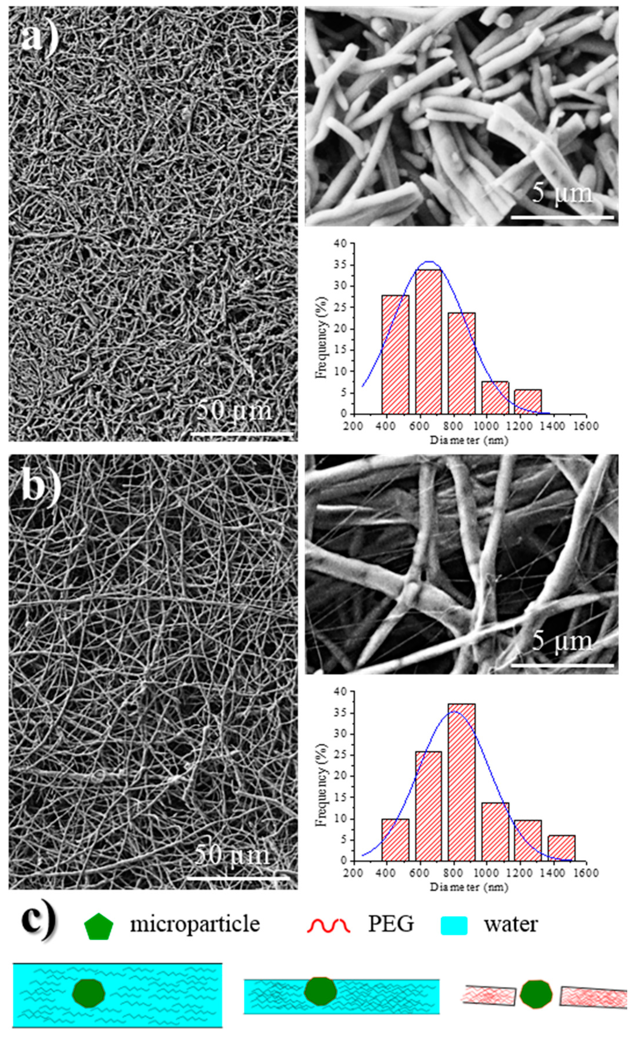
Analysis of fiber morphology from SEM micrographs demonstrated that the diameter of the fibers decreased as the conductivity of the solution increased (
Figure 6), an effect that has extensively been reported [
40]. Specifically mean diameters of 620, 652, and 818 nm (
Table 1, inset of
Figure 6) were determined for fibers coming from F, FW, and W solutions, respectively. Micrographs also revealed that the dispersion of diameter sizes decreased with solution conductivity.
Probably the main difference between electrospun fibers is their length, since those directly prepared from the Phagestaph solution had a length lower than 20 µm (
Figure 6a), while a continuous morphology was obtained from water (
Figure 6b). The presence of microparticles and a small fiber diameter are two factors that should be considered in order to justify the observed fiber breakage when a highly conductive solution is used. This problem cannot obviously be related to a typical capillary effect caused by a viscosity decrease. The Phagestaph solution contains a significant ratio of relatively large particles (the rest of bacterial lysates) that could favor breakage when the diameter of the fiber is smaller than a limiting value, as shown in
Figure 6c.
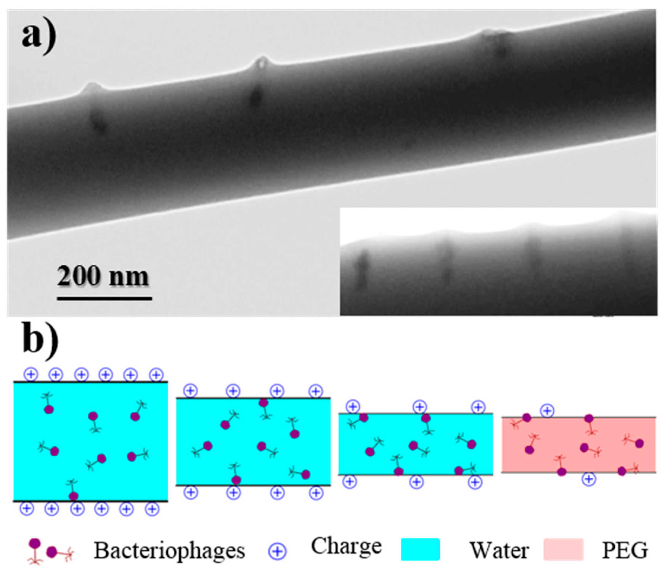
A non-homogeneous dispersion of bacteriophages inside the electrospun fibers was revealed by TEM images.
Figure 7a corresponds to the samples prepared from the WF intermediate solution, with a preferential location of bacteriophages being observed near the fiber surface and even a perpendicular orientation with respect to it. This feature is a consequence of the electrostatic interactions that were established between the positively charged polymer surface and the capsid of the phage with a preferential negative charge. Results are consistent with the well-known trend of bacteriophages to adhere on positive surfaces [
11].
Figure 7b indicates the movement and orientation of bacteriophages during the drying process.
Evaluation of bacteriophage activity by the double agar method showed a slight decrease with respect to the values obtained from the Phagestaph commercial sample used as the control (5.0 × 10³ ± 0.8 × 10³ PFU/mL). Thus, values of 4.2 × 10² ± 0.8 × 10² PFU/mL and 3.7 × 10² ± 0.6 × 10² PFU/mL were determined for the fibers processed from F and WF solutions. The most remarkable point is the fact that activity seemed not to be affected by the electrospinning process, as seen in the results obtained in the previous section. The observed activity decrease seems to be a consequence of the increase of viscosity in the agar plate produced by solubilization of PEG (i.e., the mobility of bacteriophages decreased as well as the capacity to attack bacteria, as also verified using non-electrospun samples). The lower activity of the scaffold coming from the WF solution also reflects the lower load of bacteriophages inside the fibers since the initial F solution was diluted with the same volume of water.
Literature data concerning the bacteriophage activity after performing an electrospinning process from an aqueous medium are relatively scarce, with some contradictory results also having been reported. Thus, it has been indicated that the main loss of infectivity can be related to the subsequent storage process rather than exposure to high voltage [
27]. Bacteriophages T7 and T4 were reported to survive the electrospinning process performed from an aqueous solution of poly(vinyl alcohol) and under an electrostatic field of 1 kV/cm. The bacteriophage activity remained at fairly high levels, as reported in earlier work [
29]. An intact viral structure and infecting ability of M13 bacteriophages was also observed when electrospinning was performed using a highly water-soluble polymer, PVP [
28]. However, in this case the low viscosity and high surface tension of the aqueous suspensions tended to form droplets [
28].
Nevertheless, problems related to the bacteriophage dehydration caused by the rapid evaporation of water during the single-nozzle electrospinning process have also been mentioned. Thus, negative results have been reported using a single electrospinning process based on an aqueous solution of poly(ethylene oxide), a result that contrasts with our observations. In this case, a large drop in bacteriophage activity from 10
8 to 10
3 PFU∙mL
−1 was seen [
30].
3.3. Electrospinning of PEU 1L6 Loaded with Bacteriophages
The electrospinning of both the 1L6 homopolymer and a copolymer mainly constituted by 1L6 units has recently successfully been performed using a chloroform–ethanol (10:1
v/
v) solution and a polymer
w/
v concentration between 10% [
36] and 16% [
35]. Although ethanol could affect the activity of bacteriophages, the low ratio that has been employed for the electrospinning process could preserve their activity, as will then be demonstrated. Optimal processing parameters corresponded to a voltage of 20–25 kV, a flow rate of 1.5–3.5 mL/h, and a tip–collector distance of 24.6 cm. Under these conditions continuous and homogeneous fibers with an average diameter of 2.6–2.70 µm were obtained. Therefore, the same solvent and polymer concentration were employed for the preparation of bacteriophage-loaded PEU 1L6 scaffolds. Previous experiments performed with solutions containing bactericide agents and enzymes, even at very low concentrations, demonstrated a high influence on the fiber morphology or even on the optimal electrospinning parameters (i.e., the diameter decreased to 1.29 µm and 0.46 µm when
α-chymotrypsin and the cationic poly(hexamethylene)biguanide were loaded, respectively). In addition, a flow rate of 0.5 mL/h was required when the enzyme was employed.
Freeze-dried bacteriophages were suspended in the chloroform–ethanol (10:1 v/v) solution of 1L6 at a concentration of 10% (w/v). The presence of bacteriophages in the electrospinning solution forced us to again test the optimal processing conditions, starting, however, from the above indicated parameters. A common collector distance of 24.5 cm and a voltage of 30 kV were found to be appropriate for different samples but relatively large variations in the flow rate were required depending on the type of bacteriophage loaded. Specifically, 1.5, 1.0, and 0.8 mL/h were necessary for unloaded and Phagestaph- and Fersis-loaded samples, respectively. Note that these conditions are clearly different from those determined from PEG, as expected from the different properties of polymers and of the electrospun medium (i.e., a lower polarity of chloroform with respect to water led to larger diameters and a change from a nanometric to a micrometric size).
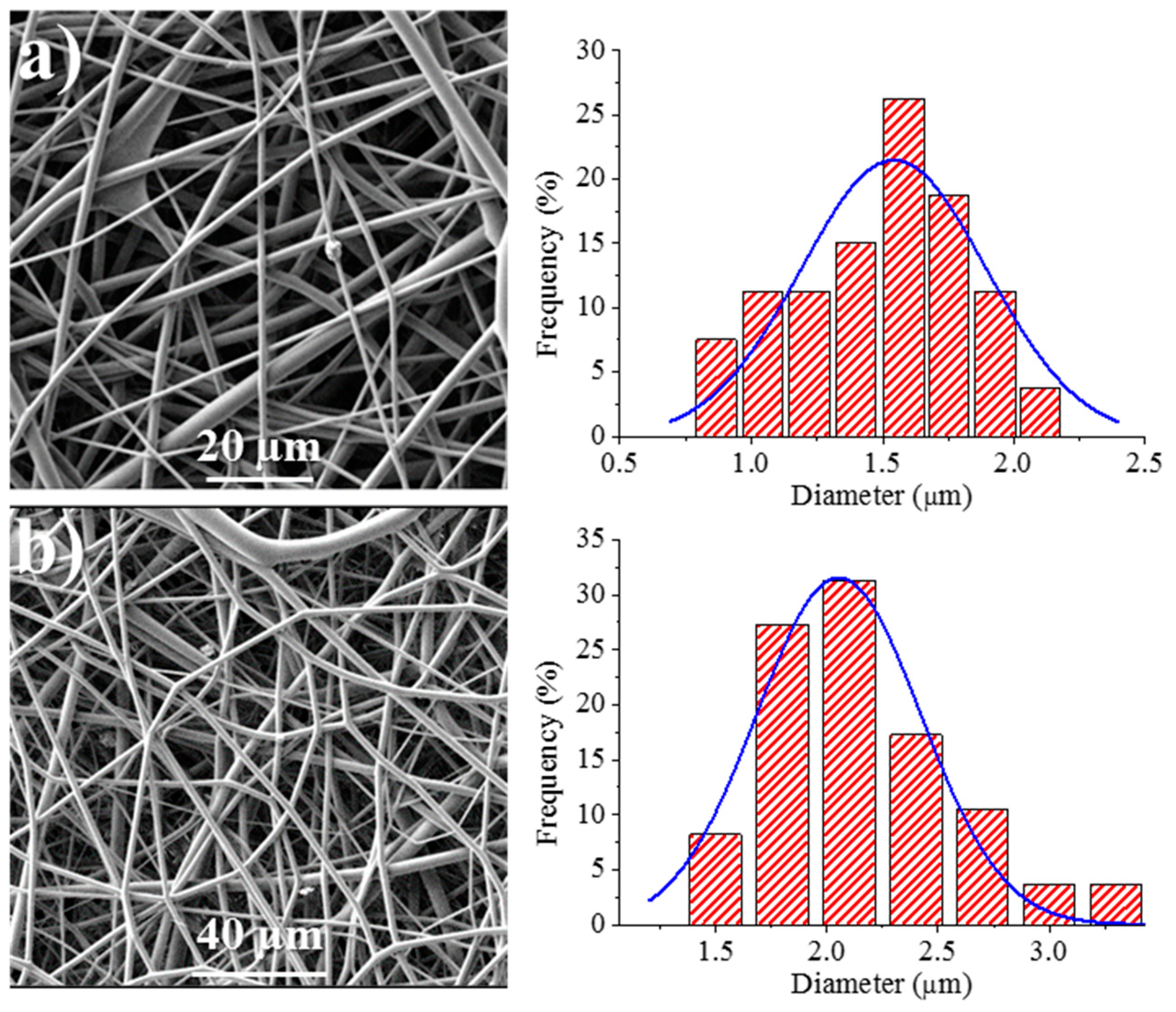
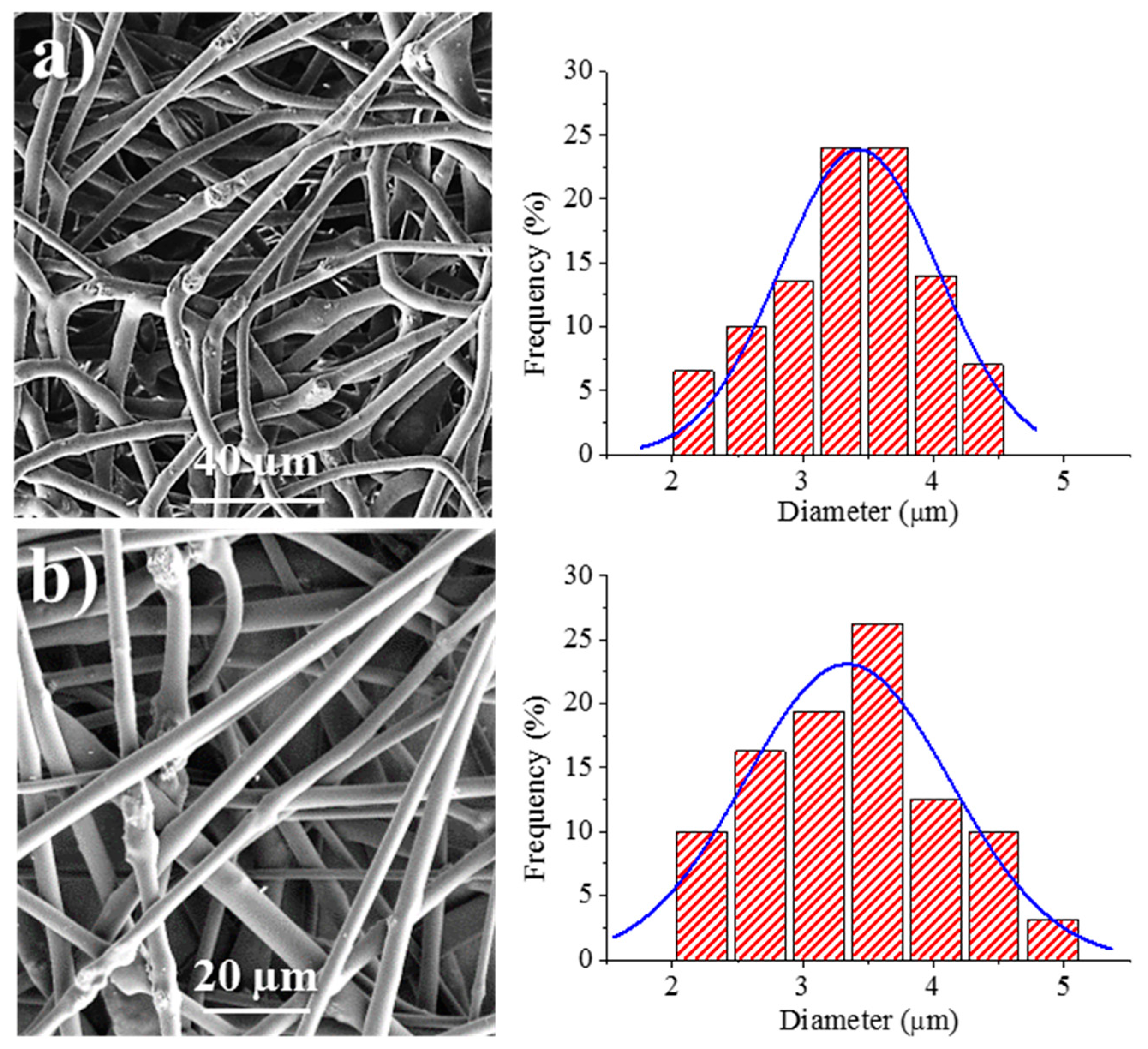
Figure 8 shows the SEM images of the 1L6 matrices loaded with the two commercial bacteriophages. It can be clearly observed in the images that the fibers had smooth surfaces, circular cross sections, and rather similar diameters that ranged in the micrometric scale. Thus, average diameters of 1.62 ± 0.32 µm and 1.95 ± 0.45 µm were determined for scaffolds incorporating Phagestaph and Fersis, respectively (
Table 2). Both values were clearly smaller than the diameter found for the unloaded 1L6 fibers (2.70 ± 0.11 µm), despite the highly similar operational parameters employed for the three samples. It should be pointed out that the electrospinning solution should contain salts and residues coming from the lyophilization of the initial bacteriophage solutions and consequently the increase of the solution conductivity had a significant influence on the diameter.
We have also optimized the conditions required for the electrospinning of calcium carbonate particles having adsorbed bacteriophages. This process has two main advantages: A problematic lyophilization process is avoided and the salts and bacteria residue that are typical of the commercial phage solution can be separated and removed. The carbonate particles (2.5% (
w/
v)) were suspended in the above indicated solution of 1L6 in chloroform–ethanol. The suspension was homogenized by magnetic stirring before performing electrospinning, with only a significant increase of the flow rate up to 5–6.7 mL/h required in order to get continuous fibers without evidence of formation of drops and/or beads.
Figure 9 shows the surface morphology of electrospun fibers prepared from the two types of bacteriophages adsorbed on carbonate. The fibers clearly reveal the presence of round protuberances associated with aggregates of carbonate particles, and appeared to be randomly distributed along the fibers. Furthermore, aggregates were well encapsulated into the fibers, which exhibited a relatively smooth texture. Average diameters were 3.45 ± 0.41 µm and 3.32 ± 0.40 µm for Phagestaph- and Fersis-loaded samples, respectively (
Table 2). A clear increase was observed with respect to samples prepared without carbonate as a logical consequence of the increase of the flow rate (i.e., 6.7 and 5 mL/h with respect to 1 and 0.8 mL/h for Phagestaph- and Fersis-loaded samples, respectively).
Morphology of bacteriophages recovered from the electrospinning process remained unaltered, as shown in
Figure S9 for two representative samples.
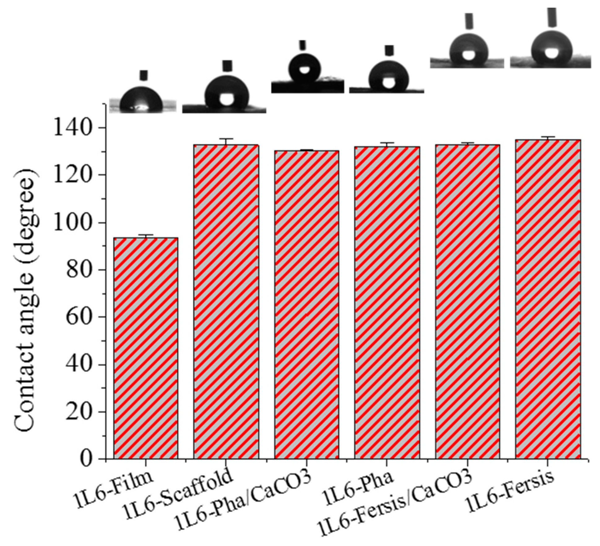
The surface properties of 1L6 microfiber matrices, loaded with bacteriophages or not, were studied using contact angle measurements. A 1L6 film sample was used as a reference, with a contact angle of 93.4° ± 1.4°. This angle increased drastically for electrospun scaffolds (132.8° ± 2.5°) as a consequence of the increased rugosity and the presence of air pockets [
41]. Scarce variations were found when samples were directly loaded with purified Phagestaph and Fersis bacteriophages or with carbonate particles having adsorbed bacteriophages. Thus, contact angles were 124.2° ± 0.7° and ±132.2° ± 1.3° for matrices loaded with Phagestaph, and 133.0° ± 1.1° and 134.9° ± 0.5° for matrices loaded with Fersis (
Figure 10). No significantly greater values were observed in each group when carbonate particles were incorporated as a consequence of the small increase in roughness and porosity caused by the greater diameter of the fibers. It is relevant that the spreading of water drops on the scaffold surface was not observed. This feature logically indicates hydrophobic interaction between water and the polymer matrix and a particularly good encapsulation of the hydrophilic carbonate particles.
3.4. Antibacterial Assays of Electrospun 1L6 Scaffolds Loaded with Bacteriophages
The antibacterial activity of the 1L6 matrix loaded with Phagestaph and Fersis bacteriophages was assessed by quantitative measurements of the inhibition of bacterial growth in broth.
S. aureus was selected to evaluate this antimicrobial effect (
Figure 11).
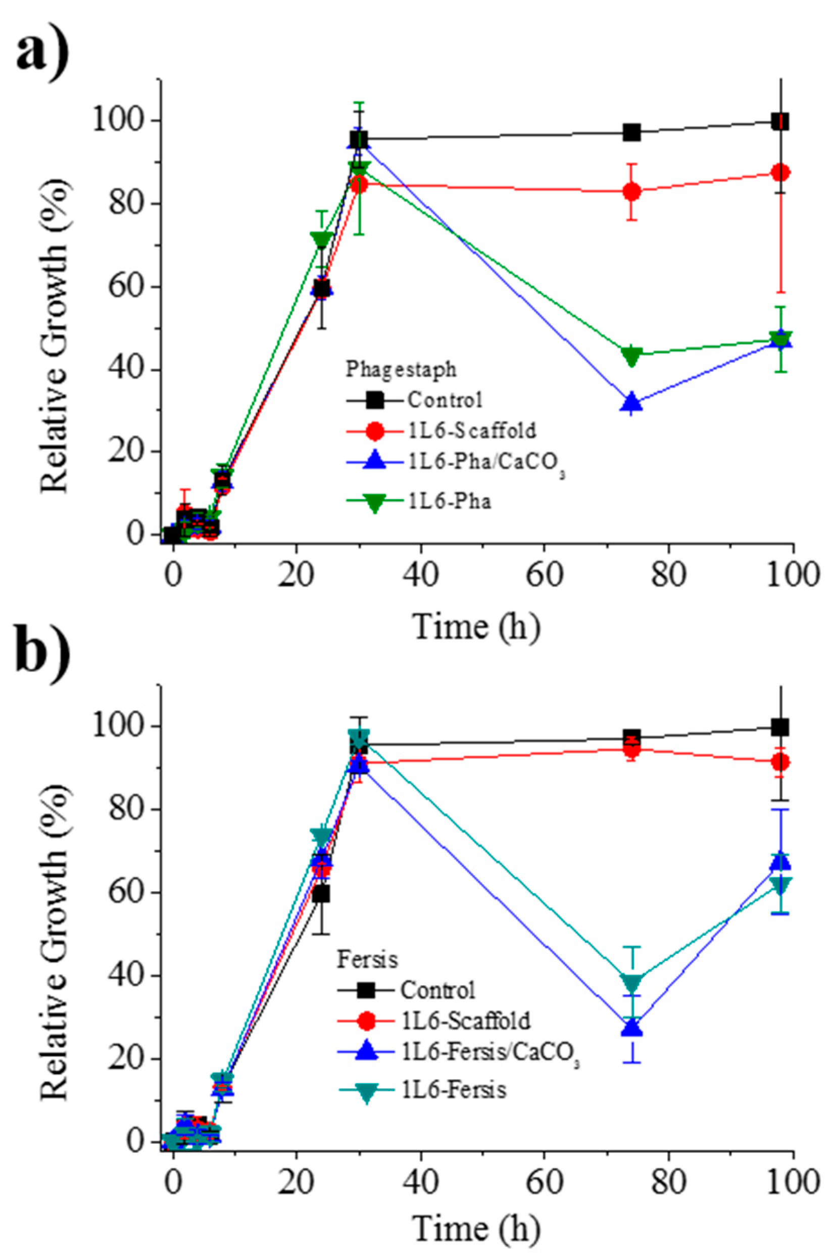
Figure 11a shows the bacterial growth curves for
S. aureus in contact with scaffolds loaded with either bacteriophages from the lyophilized Phagestaph preparation or bacteriophages from the adsorption of Phagestaph in calcium carbonate. Typical bacterial growth dynamics were found with the control sample and the unloaded 1L6 scaffold. Thus, curves showed the initial lag phase (first 6 h), the exponential growth or logarithmic phase (up to 30 h), and finally the stationary phase that lasts up to 98 h.
The inhibitory effect of scaffolds loaded with Phagestaph was clearly detected after 72 h of culture. The relative growth decreased to 30% and 42% considering the scaffolds loaded with bacteriophages adsorbed into carbonate particles and with lyophilized bacteriophages, respectively. The inhibition was similar, although a slightly higher effect was observed when the lyophilization process was avoided. Thus, adsorbed bacteriophages were highly active, with no decrease detected after a slower release. After the inhibition period, a new episode of bacterial growth took place, as can be inferred from the change on the slope of the curve. This feature is in good agreement with the well-known cyclical growth of bacteriophages.
Figure 11b shows the bacterial growth curves for
S. aureus in contact with scaffolds loaded with either bacteriophages from the lyophilized Fersis solution or bacteriophages from the adsorption of Fersis on calcium carbonate. In this case the lag phase extended up to 8 h, the exponential phase up to 30 h, and the stationary phase up to 98 h. The inhibition effect was also detected after 72 h; specifically, the relative growth decreased to 60% and 48%, with better results again obtained when non-lyophilized samples were employed. After this period, a new episode of bacterial growth took place.
Lytic activity of the different 1L6 scaffolds loaded with bacteriophages and determined by the double agar method is compared in
Table 3. Results obtained with Fersis and Phagestaph are rather similar and allow us to make the following general conclusions: (a) The activity of the initial phage solutions slightly decreased when a lyophilization step was necessary (i.e., from 5 × 10
3 to 1 × 10
3 PFU/mL for Phagestaph and from 4 × 10
3 to 3 × 10
3 PFU/mL for Fersis); (b) adsorption of bacteriophages onto calcium carbonate particles did not cause a significant decrease in activity; (c) the electrospinning process did not produce a loss of phage activity despite the use of organic solvents and the application of an electric field; d) scaffolds with greater activity and specifically with similar values to those attained with the initial/commercial preparations were obtained by the incorporation of calcium carbonate particles on which bacteriophages were previously adsorbed. All these changes were small because the exponent value was always conserved when counting PFU.
Positive results concerning the activity of bacteriophages after electrospinning from an organic solvent are scarce. Probably, the most clear result was obtained with poly(
ε-caprolactone)/collagen electrospun membranes from 1,1,1,3,3,3-hexafluoroisopropanol solutions. These exhibited an optimal antibacterial effect with an inhibition efficiency of
E. coli activity above 90% [
15]. In this sense, the use of the selected poly(ester urea), a chloroform–ethanol medium and the adsorption of bacteriophages into CaCO
3 particles appear an interesting methodology to provide new scaffolds with preserved bacteriophage activity.
3.5. Biocompatibility of Electrospun 1L6 Scaffolds Loaded with Bacteriophages
1L6 scaffolds prepared by electrospinning had a tridimensional pore structure that turns out to be an excellent support for the adhesion and growth of eukaryotic cells.
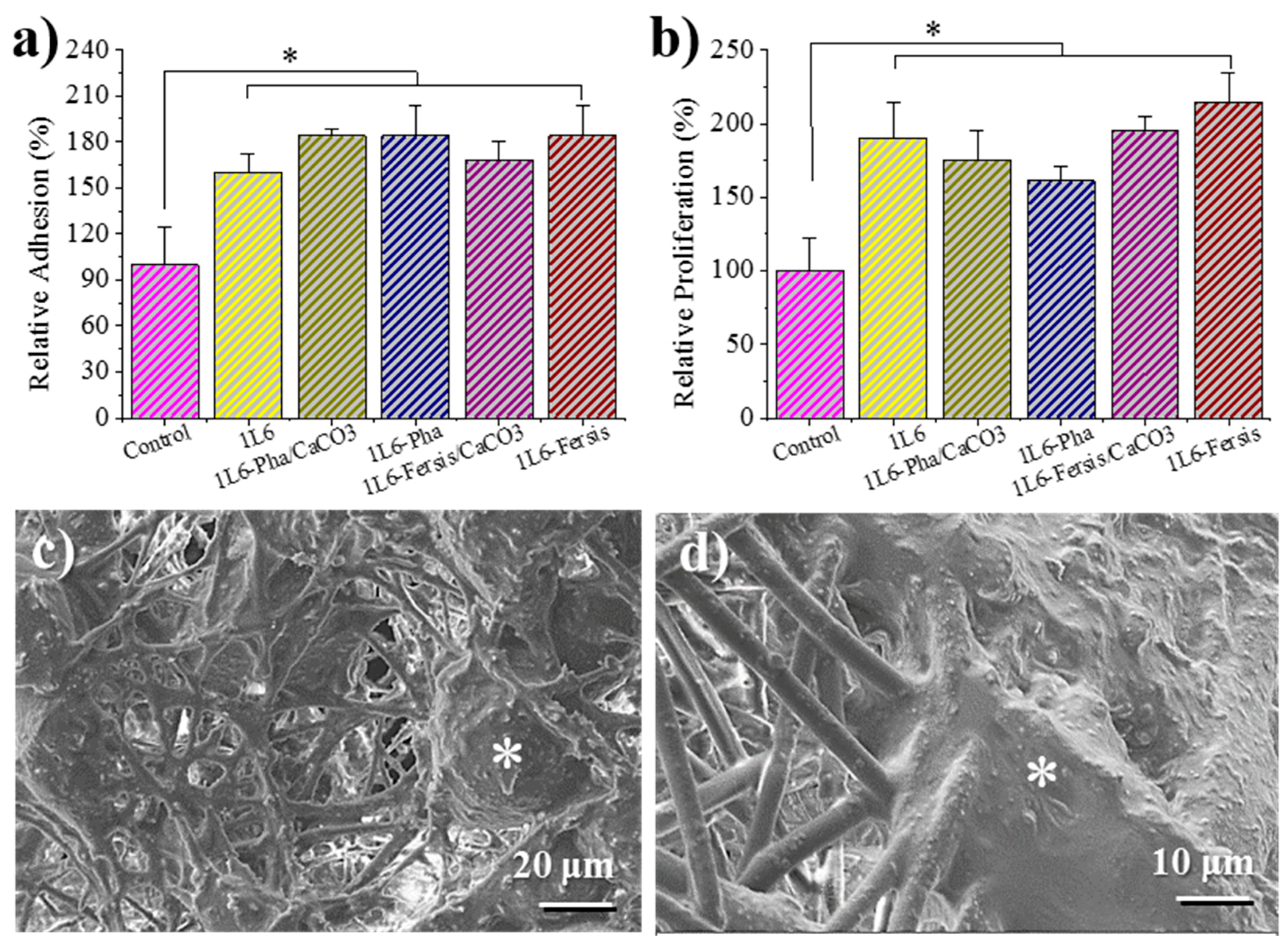
Figure 12a shows that the adhesion percentages for Vero cells (epithelial cells) were higher for 1L6 scaffolds than for the control (2D surface of the culture plate). The best adhesion results were obtained for 1L6 scaffolds loaded with Phagestaph independently of being prepared from the lyophilized commercial solution or through calcium carbonate particles. In the case of Fersis, the adhesion results were slightly worse, but still better than determined for the control.
Vero cells proliferated better with respect to the control on both unloaded 1L6 matrices and those incorporating phages (
Figure 12b). Phagestaph-loaded samples displayed slightly lower proliferation than the unloaded scaffold, with no significant differences detected between the two loading procedures. It should be pointed out that scaffolds loaded with Fersis showed higher proliferation percentages despite the result not being so positive when the first adhesion event was considered.
In summary, growth percentages were always significantly (p < 0.05) higher than those determined for the control. Thus, it was possible to infer that new scaffolds were fully biocompatible and that encapsulated bacteriophages were not cytotoxic for Vero epithelial cells.
Micrographs of cellular monolayers grown onto the scaffolds loaded with phages coming from lyophilized Phagestaph and Fersis preparations are given in
Figure 12c,d. The SEM images clearly demonstrate that loaded bacteriophages did not cause a cytopathic effect in Vero cells. The cells’ monolayer was well formed, as shown by the intimate contact between cells, and cell spreading was able to colonize the scaffold through its porous structure.

 ,
, 


