A Brief Review of New Fiber Microsphere Geometries
by
 , and
, and
André Delgado Gomes
1,2,3 ,
,
Catarina Silva Monteiro
1,2,
Beatriz Silveira
1,3 and
Orlando Frazão
1,2,* 1
Centre for Applied Photonics, Institute for Systems and Computer Engineering, Technology and Science (INESC TEC), 4169-007 Porto, Portugal
2
Department of Physics and Astronomy, Faculty of Sciences, University of Porto, 4169-007 Porto, Portugal
3
Leibniz Institute of Photonic Technology, 07745 Jena, Germany
*
Author to whom correspondence should be addressed.
Fibers 2018, 6(3), 48; https://doi.org/10.3390/fib6030048
Submission received: 13 June 2018
/
Revised: 29 June 2018
/
Accepted: 6 July 2018
/
Published: 11 July 2018
(This article belongs to the Special Issue Optical Fiber Communications)
Abstract
:A brief review of new fiber microsphere geometries is presented. Simple microspheres working as Fabry–Perot cavities are interrogated in reflection and in transmission. Two microspheres were also spliced together, and subjected to different physical parameters. These structures are an alternative solution for load measurement and, when read in transmission, it is also possible to apply strain. Moreover, the structure is capable of being used under extreme ambient temperatures up to 900 °C. Random signal in cleaved microspheres was demonstrated with the possibility of using it for random laser or sensing applications. All this work was developed at the Centre for Applied Photonics, INESC TEC.
1. Introduction
Microspheres integrated in optical fiber devices have been a matter of research over the last two decades. Due to the optical characteristics of microspheres, many practical applications were proposed in the literature for sensing and lasing.
The first reported microsphere fabricated on the end of an optical fiber used a hydrogen–oxygen torch to form several microspheres, with radii ranging from 50 to 125 µm [1]. The spherical fiber end was used to couple light from a GaAs laser diode to a fiber, achieving more than 50% coupling efficiency. Some years later, the usage of a CO2 laser was proposed for the formation of a spherical lens at the tip of optical fibers [2]. Since then, several fabrication techniques were proposed for the fabrication of hollow and solid microspheres, such as the use of a femtosecond laser [3] or a fusion splicing machine [4,5,6].
Microspheres created on top of optical fibers were vastly explored given the possibility of exciting whispering gallery modes [5], opening new paths in different fields of research. Moreover, this kind of structure can also be produced to work as interferometric cavities. For instance, a three-wave interferometer was demonstrated using a hollow-core microsphere on a fiber tip [6]. For an inline configuration, this structure can also behave as a two-wave interferometer. When subjected to temperature variations, the first configuration presented a sensitivity of 1.90 pm/°C, while for the inline configuration, a sensitivity of 1.17 pm/°C was reported. An array of silica microspheres was also proposed for temperature sensing, achieving a sensitivity of 20.3 pm/°C [7].
In this paper, a brief review of new designs for silica microspheres and their application as all-fiber sensors and lasers is presented.
2. Multipath Interferometers with Cleaved Microspheres
Simple silica microspheres, made from single mode fiber (SMF), work as concave mirrors, focusing the small amount of light originated from the Fresnel reflection at the tip of the microsphere. Apart from the fact that they can be used as intensity sensors, just like a simple cleaved fiber tip, these structures do not show any significant interferometric behavior suitable for sensing applications. Therefore, techniques, such as conventional peak wavelength-shift inspection methods, cannot be applied in these cases.
Recently, two works explored the generation of multiple optical paths inside of microspheres by creating asymmetry in the structure. The concept consists in cleaving or polishing a microsphere at a certain angle, forcing part of the light to be reflected in different directions inside the microsphere. The interference of these multiple reflections gives rise to a unique interference pattern. The reflected signal is measured using a simple interrogation setup, similar to the one described in Figure 1. The setup comprises a broadband optical source, an optical circulator, and an optical spectrum analyzer (OSA).
The first reported work used a focused ion beam (FIB) to cleave a 322 µm-diameter silica microsphere with an angle of around 20° in relation to the fiber’s longitudinal axis, as shown in the schematic of Figure 2 [8]. The microsphere was produced by applying multiple electric arcs near the end of a cleaved single mode fiber, using a fusion splicer. The authors obtained a reflection spectrum with a random-like interferometric behavior and strong spectral modulation (around 3 dB), as depicted in Figure 2. The fast Fourier transform (FFT) of the reflected signal exhibited two distinct regions. The first was composed of two peaks at low frequency that correspond to cavities. The cavity length corresponding to these peaks corresponds to a reflection on the microsphere’ edge, and to a second reflection of light on the cleaved region. As a result of this second reflection, part of the light is deviated, and travels around the microsphere, following a larger optical path distance. Temperature variations only introduce a small change in the cavity length of those components. However, the second region of the FFT corresponds to a band of higher frequencies, as a result from the interference between multiple optical paths that were generated inside of the microsphere. This band of higher frequencies changes considerably with temperature.
The structure was proposed for temperature sensing and a correlation method was used to extract the temperature response from the two-cavity component. The sensor presented a temperature sensitivity of −10.8 pm/°C from 80 °C to 30 °C.
A similar experiment was also conducted using a polished microsphere of multimode fiber [9]. A focused CO2 laser was used to fabricate a 270 µm-diameter microsphere at the edge a multimode fiber tip. Instead of cleaving the structure, the authors proposed a simple way to polish the microsphere with a particular angle, using a stainless-steel needle, a protractor, and a polishing stage, therefore avoiding the use of expensive techniques, such as FIB. The final structure was a microsphere polished with an angle of around 30° in relation to the fiber’s longitudinal axis, as depicted in Figure 3. Similarly to that obtained in the previous work, the reflection spectrum of such structure is a random-like interference pattern that changes with temperature. The authors explained that the interferometric spectral modulation is equivalent to the overlap of multiple two-wave interferometers, and therefore, the FFT presents peaks at different frequencies. They demonstrated the feasibility of extracting the different spectral components through signal processing, monitoring each of the peaks as a function of temperature. Among the cavity components, a temperature sensitivity enhancement was achieved for lower-length interferometers (lower frequency components) with a sensitivity of 45 pm/°C, three times bigger when compared with higher frequency components (15.9 pm/°C). The authors also demonstrated the capability of using correlation analysis to obtain a temperature sensitivity without the need to filter each component individually. For this method, the obtained temperature sensitivity was 50 pm/°C.
3. Modified Microspheres for Random Lasing
Random lasers are a class of lasers without a well-defined cavity, in which the modes are determined by the interference of multiple scattering [10]. This new type of laser appeared during the last decade, and presents attractive advantages over other lasers, viz. simple technology, low production cost [11], light weight, and immunity to light source oscillations [12]. These features allowed for developments in multiple areas, and applications include fiber and nonlinear optics, laser physics [11], secure optical communications [13], random number generation [14], fiber fault detection [15,16,17,18,19], and sensing [20,21,22]. For sensing, optical random signals were used for compressive sensing [22]. An improved alternative to the well-known fiber cavity ring down technique was also proposed using random signals, creating a random correlation fiber loop ring down [12]. Random correlation was revealed to be a powerful tool to analyze more complicated systems where traditional interrogation techniques cannot be applied [18].
Recently, a random fiber laser was demonstrated based on the concept of a random fiber Bragg grating (FBG) in a ring configuration [23]. The lasing process is established through the interference between light beams with different optical paths along the ring resonator. In a similar way, asymmetric microspheres can be incorporated in a ring resonator structure with gain medium to create a random laser, as shown in Figure 4. The setup consists of an erbium doped fiber amplifier (EDFA), an optical circulator connected to the modified microsphere, and a 90/10 coupler to create the ring cavity, while simultaneously reading the output in an optical spectrum analyzer. The constructive interferences inside the microsphere are re-amplified, giving rise to one or more lasing lines.
For this purpose, two modified microspheres were developed. The first one is inspired in the Bunimovich stadium-shaped chaotic structure, and its fabrication only requires a fusion splicer and a fiber cleaver. The authors produced the stadium-shaped microsphere by merging two conventional silica microspheres, by applying multiple low-power electrical discharges. The final result is a stadium-shaped microsphere, identical to the one presented in the schematic of Figure 5.
The second proposed modified microsphere relies on the use of focused ion beam (FIB) milling to create a decentered circular hole near the tip of a microsphere, in order to promote light scattering into different directions inside of the silica structure. A schematic of the circular-milled microsphere is shown in Figure 6.
Both structures were coated with a gold thin film to act as a mirror, confining the light inside the microsphere, reducing losses, and increasing the number of reflections. Using the abovementioned setup, the spectra of both microspheres presented multiple lasing lines in the region of highest gain of the erbium profile, as visible in the output of Figure 5 and Figure 6. The multiple lasing lines also change in time, due to the modes’ competition for gain [12,24].
4. Interferometric Hollow Microspheres
Hollow silica microspheres work as multi-mirror Fabry–Perot interferometers, and several physical and chemical sensing applications were proposed in literature [6,25]. The incorporation of hollow microspheres in optical fibers have been proposed through the use of chemical etching [26], catastrophic fuse effect [27], or fusion splicing [28]. The fusion splice technique differentiates itself as an easy fabrication technique that presents no chemical hazards. Hollow microspheres can be fabricated through fusion splicing techniques in standard single mode fibers [29], photonic crystal fibers (PCF) [5,30,31], or in hollow core fibers (HCF) [32,33]. Particularly, the use of HCFs allows a simple and fast hollow microsphere fabrication. Recently, two works have been proposed in literature [32,33] where hollow microspheres were created using an HCF spliced to an SMF. Using a fusion splicer, two electric arcs were applied at the tip of the HCF, reshaping the fiber into a hollow microsphere with thin silica walls.
Single-microsphere-based sensors using two different configurations were demonstrated in the last year [32]. A microsphere with an air cavity length of 175 µm and a 30 µm-thick silica wall was presented, as schematized in Figure 7. The spectrum of the sensing structure, which can be approximated to a three-wave Fabry–Perot interferometer, was attained using a simple reflection scheme consisting of a broadband source, an optical circulator, and an OSA, as previously schematized in Figure 1.
To obtain the different spectral components that form the reflected signal, the signal processing analysis showed in the schematic of Figure 8 is performed. First an FFT of the reflected signal is calculated, where each peak of the FFT correspond to the interference between two waves. In order to extract each of the interferometric components separately, a bandpass filter can be used to select a single peak in the FFT. In the end, only a single frequency (single interferometer) from the reflected signal is obtained after applying the filter.
The microsphere with an air cavity was studied for lateral load and temperature. For the load characterization, a load was applied to the fiber tip, perpendicularly to the fiber’s longitudinal direction. Due to the sensor geometry, the load was applied using a three-point scheme that evenly divides the pressure between the points. The lateral load was varied between 0 and 1.2 N, achieving a sensitivity of 1.56 nm/N. The thermal response was studied by placing the fiber tip in a tubular oven, and varying the temperature between 300 °C and 500 °C. The tip microsphere attained a sensitivity of 1.90 pm/°C.
The second reported structure was an inline microsphere that can be approximated to a two-wave interferometer, as depicted in Figure 9. This configuration presented a much simpler spectrum, providing also the possibility of strain-sensing. The inline microsphere attained a load sensitivity of 2.62 pm/N. This sensing structure achieved a much higher sensitivity when compared with the tip structure. Such higher value of sensitivity can be explained by the thinner silica walls of the inline structure, which suffered higher deformation in comparison with the tip structure when load was applied. The inline configuration presented a very similar behavior to the tip structure in terms of temperature characterization, with an achieved thermal sensitivity of 1.17 pm/°C, for temperatures between 250 °C and 600 °C. The inline configuration was also proposed as a strain sensor, achieving a sensitivity of 4.66 pm/µε for a maximum of 1000 µε of applied strain.
Recently, a two-microsphere structure was presented in the literature [33]. Two hollow microspheres were fabricated at the tip of an SMF using hollow core fiber and, afterwards, the microspheres where fusion spliced together. The final sensing head could be approximated to a four-wave interferometer when monitoring the reflected signal, as shown in Figure 10. Two similar configurations were characterized for strain, attaining a maximum strain sensitivity of 4.07 pm/µε on a range of 2000 µε. The structure presented a low thermal sensitivity of 2.1 pm/°C for temperatures between 200 °C and 500 °C. When compared with an array of two solid microspheres [7], the hollow microsphere configuration presented a strain sensitivity more than four times higher, with a ten times lower thermal sensitivity.
In Table 1, a strain sensitivity comparison between some types of Fabry–Perot structures is shown. The cavity structures are listed with increasing strain sensitivity. In bold, two different hollow microsphere cavities are presented.
5. Conclusions
A brief insight on the recent developments in new fiber microsphere geometries was presented and discussed. The reported works show the ability to modify the structure of conventional microspheres, or even to create new types of microspheres, such as a hollow microsphere, in order to generate new effects or enhance other properties. Multi-path interferometers were obtained by breaking the symmetry of conventional microspheres, by means of cleaving the microspheres using focused ion beam milling or by polishing techniques. The use of such structures as sensing elements was explored. The same idea of breaking the microsphere geometry was explored to create chaos for applications in random lasers. Geometries, such as the Bunimovich stadium-like microsphere or the decentered circular-milled microsphere were discussed. Hollow microspheres in different kinds of configurations were also reported. They can act as two-wave or three-wave interferometers with high potential for sensing applications, especially for simultaneous measurements of physical, chemical, or biological parameters. In the future, the application of these new microsphere geometries in pressure sensing and in flow sensing for medical purposes could be addressed.
Author Contributions
Writing—Original Draft Preparation, A.D.G., C.S.M. and B.S.; Writing—Review & Editing, O.F.
Funding
Project NanoSTIMA—North Portugal Regional Operational Programme (NORTE-01-0145-FEDER-000016).
Acknowledgments
André Gomes is funded by FCT (SFRH/BD/129428/2017). Catarina Monteiro is funded by (M-ERA-NET2/0002/2016). Beatriz Silveira is funded by NanoSTIMA—North Portugal Regional Operational Programme (NORTE-01-0145-FEDER-000016), and COST Action MP1401 (39232)—European Cooperation in Science and Technology.
Conflicts of Interest
The authors declare no conflict of interest.
References
- Kato, D. Light coupling from a stripe-geometry GaAs diode laser into an optical fiber with spherical end. J. Appl. Phys. 1973, 44, 2756–2758. [Google Scholar] [CrossRef]
- Paek, U.C.; Weaver, A.L. Formation of a Spherical Lens at Optical Fiber Ends with a CO2 Laser. Appl. Opt. 1975, 14, 294–298. [Google Scholar] [CrossRef] [PubMed]
- Liao, C.R.; Hu, T.Y.; Wang, D.N. Optical fiber Fabry-Perot interferometer cavity fabricated by femtosecond laser micromachining and fusion splicing for refractive index sensing. Opt. Express 2012, 20, 22813–22818. [Google Scholar] [CrossRef] [PubMed]
- Chen, X.; Shen, F.; Wang, Z.; Huang, Z.; Wang, A. Micro-air-gap based intrinsic Fabry-Perot interferometric fiber-optic sensor. Appl. Opt. 2006, 45, 7760–7766. [Google Scholar] [CrossRef] [PubMed]
- Jáuregui-Vázquez, D.; Estudillo-Ayala, J.M.; Rojas-Laguna, R.; Vargas-Rodr, E.; Sierra-Hernández, J.M.; Hernández-García, J.C.; Mata-Chávez, R.I. An all fiber intrinsic Fabry-Perot interferometer based on an air-microcavity. Sensors 2013, 13, 6355–6364. [Google Scholar] [CrossRef] [PubMed]
- Yan, L.; Gui, Z.; Wang, G.; An, Y.; Gu, J.; Zhang, M.; Liu, X.; Wang, Z.; Wang, G.; Jia, P. A micro bubble structure based fabry-perot optical fiber strain sensor with high sensitivity and low-cost characteristics. Sensors 2017, 17, 555. [Google Scholar] [CrossRef] [PubMed]
- Ferreira, M.S.; Santos, J.L.; Frazão, O. Silica microspheres array strain sensor. Opt. Lett. 2014, 39, 5937–5940. [Google Scholar] [CrossRef] [PubMed]
- Gomes, A.D.; Silveira, B.; Dellith, J.; Becker, M.; Rothhard, M.; Bartelt, H.; Frazao, O. Cleaved Silica Microsphere for Temperature Measurement. IEEE Photonics Technol. Lett. 2018, 30, 797–800. [Google Scholar] [CrossRef]
- Gomes, A.D.; Karami, F.; Zibaii, M.I.; Latifi, H.; Frazo, O. Multipath Interferometer Polished Microsphere for Enhanced Temperature Sensing. IEEE Sens. Lett. 2018, 2, 1–4. [Google Scholar] [CrossRef]
- Wiersma, D.S. The physics and applications of random lasers. Nat. Phys. 2008, 4, 359–367. [Google Scholar] [CrossRef]
- Turitsyn, S.K.; Babin, S.A.; Churkin, D.V.; Vatnik, I.D.; Nikulin, M.; Podivilov, E.V. Random distributed feedback fibre lasers. Phys. Rep. 2014, 542, 133–193. [Google Scholar] [CrossRef]
- Yang, L.; Yang, J.; Yang, Y.; Zhang, Z.; Wang, J.; Zhang, Z.; Xue, P.; Gong, Y.; Copner, N. Optical sensors using chaotic correlation fiber loop ring down. Opt. Express 2017, 25, 2031–2037. [Google Scholar] [CrossRef] [PubMed]
- Argyris, A.; Syvridis, D.; Larger, L.; Annovazzi-Lodi, V.; Colet, P.; Fischer, I.; García-Ojalvo, J.; Mirasso, C.R.; Pesquera, L.; Shore, K.A. Chaos-based communications at high bit rates using commercial fibre-optic links. Nature 2005, 438, 343–346. [Google Scholar] [CrossRef] [PubMed]
- Uchida, A.; Amano, K.; Inoue, M.; Hirano, K.; Naito, S.; Someya, H.; Oowada, I.; Kurashige, T.; Shiki, M.; Yoshimori, S.; et al. Fast physical random bit generation with chaotic semiconductor lasers. Nat. Photonics 2008, 2, 728–732. [Google Scholar] [CrossRef] [Green Version]
- Wang, Y.; Wang, B.; Wang, A. Chaotic Correlation Optical Time Domain Reflectometer Utilizing Laser Diode. IEEE Photonics Technol. Lett. 2008, 20, 1636–1638. [Google Scholar] [CrossRef]
- Wang, A.; Wang, N.; Yang, Y.; Wang, B.; Zhang, M.; Wang, Y. Precise fault location in WDM-PON by utilizing wavelength tunable chaotic laser. J. Lightwave Technol. 2012, 30, 3420–3426. [Google Scholar] [CrossRef]
- Xia, L.; Huang, D.; Xu, J.; Liu, D. Simultaneous and precise fault locating in WDM-PON by the generation of optical wideband chaos. Opt. Lett. 2013, 38, 3762–3764. [Google Scholar] [CrossRef] [PubMed]
- Luo, Y.; Xia, L.; Xu, Z.; Yu, C.; Sun, Q.; Li, W.; Huang, D.; Liu, D. Optical chaos and hybrid WDM/TDM based large capacity quasi-distributed sensing network with real-time fiber fault monitoring. Opt. Express 2015, 23, 2416–2423. [Google Scholar] [CrossRef] [PubMed]
- Wang, Z.N.; Fan, M.Q.; Zhang, L.; Wu, H.; Churkin, D.V.; Li, Y.; Qian, X.Y.; Rao, Y.J. Long-range and high-precision correlation optical time-domain reflectometry utilizing an all-fiber chaotic source. Opt. Express 2015, 23, 15514–15520. [Google Scholar] [CrossRef] [PubMed]
- Xu, Y.; Lu, P.; Gao, S.; Xiang, D.; Lu, P.; Mihailov, S.; Bao, X. Optical fiber random grating-based multiparameter sensor. Opt. Lett. 2015, 40, 5514–5517. [Google Scholar] [CrossRef] [PubMed]
- Zhang, J.; Yang, L.; Yang, H.; Zhang, L.; Wang, J.; Zhang, Z. A novel demodulation scheme for high precision quasi-distributed sensing system based on chaotic fiber laser. Sens. Actuators A: Phys. 2015, 233, 427–433. [Google Scholar] [CrossRef]
- Rontani, D.; Choi, D.; Chang, C.-Y.; Locquet, A.; Citrin, D.S. Compressive Sensing with Optical Chaos. Sci. Rep. 2016, 6, 35206. [Google Scholar] [CrossRef] [PubMed] [Green Version]
- Xu, Y.; Zhang, M.; Lu, P.; Mihailov, S.; Bao, X.; Canada, C. Multi-parameter fiber-optic sensors based on fiber random grating. In Proceedings of the 2017 25th Optical Fiber Sensors Conference, Jeju, Korea, 24–28 April 2017; pp. 1–4. [Google Scholar] [CrossRef]
- Cao, H. Review on latest developments in random lasers with coherent feedback. J. Phys. A: Math. Gen. 2005, 38. [Google Scholar] [CrossRef]
- Hu, D.J.J.; Wang, Y.; Lim, J.L.; Zhang, T.; Mileńko, K.B.; Chen, Z.; Jiang, M.; Wang, G.; Luan, F.; Shum, P.P.; et al. Novel miniaturized fabry-perot refractometer based on a simplified hollow-core fiber with a hollow silica sphere tip. IEEE Sens. J. 2012, 12, 1239–1245. [Google Scholar] [CrossRef]
- Cibula, E.; Donlagic, D. In-line short cavity Fabry-Perot strain sensor for quasi distributed measurement utilizing standard OTDR. Opt. Express 2007, 15, 8719–8730. [Google Scholar] [CrossRef] [PubMed]
- Antunes, P.F.C.; Domingues, M.F.F.; Alberto, N.J.; André, P.S. Optical fiber microcavity strain sensors produced by the catastrophic fuse effect. IEEE Photonics Technol. Lett. 2014, 26, 78–81. [Google Scholar] [CrossRef]
- Dong, B.; Hao, J.; Zhang, T.; Lim, J.L. High sensitive fiber-optic liquid refractive index tip sensor based on a simple inline hollow glass micro-sphere. Sens. Actuators B: Chem. 2012, 171, 405–408. [Google Scholar] [CrossRef]
- Liu, S.; Yang, K.; Wang, Y.; Qu, J.; Liao, C.; He, J.; Li, Z.; Yin, G.; Sun, B.; Zhou, J.; et al. High-sensitivity strain sensor based on in-fiber rectangular air bubble. Sci. Rep. 2015, 5, 7624. [Google Scholar] [CrossRef] [PubMed] [Green Version]
- Villatoro, J.; Finazzi, V.; Coviello, G.; Pruneri, V. Photonic-crystal-fiber-enabled micro-Fabry-Perot interferometer. Opt. Lett. 2009, 34, 2441–2443. [Google Scholar] [CrossRef] [PubMed]
- Cano-Contreras, M.; Guzman-Chavez, A.D.; Mata-Chavez, R.I.; Vargas-Rodriguez, E.; Jauregui-Vazquez, D.; Claudio-Gonzalez, D.; Estudillo-Ayala, J.M.; Rojas-Laguna, R.; Huerta-Mascotte, E. All-fiber curvature sensor based on an abrupt tapered fiber and a Fabry-Pérot interferometer. IEEE Photonics Technol. Lett. 2014, 26, 2213–2216. [Google Scholar] [CrossRef]
- Monteiro, C.; Silva, S.; Frazao, O. Hollow microsphere fabry-perot cavity for sensing applications. IEEE Photonics Technol. Lett. 2017, 29, 1229–1232. [Google Scholar] [CrossRef]
- Monteiro, C.S.; Kobelke, J.; Schuster, K.; Bierlich, J.; Frazão, O. Fabry-Perot sensor based on two coupled microspheres for strain measurement. In Proceedings of the Optical Fiber Sensors Conference, Jeju, Korea, 24–28 April 2017; Chung, Y., Jin, W., Lee, B., Canning, J., Nakamura, K., Yuan, L., Eds.; p. 103232. [Google Scholar]
- Shi, Q.; Lv, F.; Wang, Z.; Jin, L.; Hu, J.J.; Liu, Z.; Kai, G.; Dong, X. Environmentally Stable Fabry-Pérot-Type Strain Sensor Based On Hollow-Core Photonic Bandgap Fiber. IEEE Photonics Technol. Lett. 2008, 20, 2008–2010. [Google Scholar] [CrossRef]
- Gong, Y.; Rao, Y.; Guo, Y.; Ran, Z.-L.; Wu, Y. Temperature-Insensitive Micro Fabry-Perot Strain Sensor Fabricated by Chemically Etching Er-Doped Fiber. IEEE Photonics Technol. Lett. 2009, 21, 1725–1727. [Google Scholar] [CrossRef]
- Rao, Y.-J.; Deng, M.; Duan, D.-W.; Yang, X.-C.; Zhu, T.; Cheng, G.-H. Micro Fabry-Perot interferometers in silica fibers machined by femtosecond laser. Opt. Express 2007, 15, 14123–14128. [Google Scholar] [CrossRef] [PubMed]
- Favero, F.C.; Araujo, L.; Bouwmans, G.; Finazzi, V.; Villatoro, J.; Pruneri, V. Spheroidal Fabry-Perot microcavities in optical fibers for high-sensitivity sensing. Opt. Express 2012, 20, 7112–7118. [Google Scholar] [CrossRef] [PubMed]
Figure 1.
Schematic diagram of the interrogation setup.

Figure 2.
Schematic of the focused ion beam cleaved microsphere and its reflection spectrum. Reproduced withpermission from [8]. IEEE Photonics Technology Letters, 2018.
Figure 2.
Schematic of the focused ion beam cleaved microsphere and its reflection spectrum. Reproduced withpermission from [8]. IEEE Photonics Technology Letters, 2018.

Figure 3.
Schematic diagram of the polished microsphere and its reflection spectrum. Reproduced with permission from [9]. IEEE Sensors Letters, 2018.
Figure 3.
Schematic diagram of the polished microsphere and its reflection spectrum. Reproduced with permission from [9]. IEEE Sensors Letters, 2018.

Figure 4.
Schematic diagram of the ring structure for random lasing, using asymmetric microspheres.

Figure 5.
Schematic diagram of a stadium-shaped microsphere and output signal, when using the microsphere in the ring structure illustrated in Figure 4.
Figure 5.
Schematic diagram of a stadium-shaped microsphere and output signal, when using the microsphere in the ring structure illustrated in Figure 4.

Figure 6.
Schematic diagram of a circular-milled microsphere and output signal, when using the microsphere in the ring structure illustrated in Figure 4.
Figure 6.
Schematic diagram of a circular-milled microsphere and output signal, when using the microsphere in the ring structure illustrated in Figure 4.

Figure 7.
(a) Reflection spectrum and respective (b) FFT. (c) The corresponding optical cavities for each FFT peak.
Figure 7.
(a) Reflection spectrum and respective (b) FFT. (c) The corresponding optical cavities for each FFT peak.

Figure 8.
Signal processing steps to identify and separate each component of the reflection spectrum.
Figure 8.
Signal processing steps to identify and separate each component of the reflection spectrum.

Figure 9.
(a) Reflection spectrum of the inline hollow microsphere and (b) respective FFT with an inset representing the optical cavity.
Figure 9.
(a) Reflection spectrum of the inline hollow microsphere and (b) respective FFT with an inset representing the optical cavity.
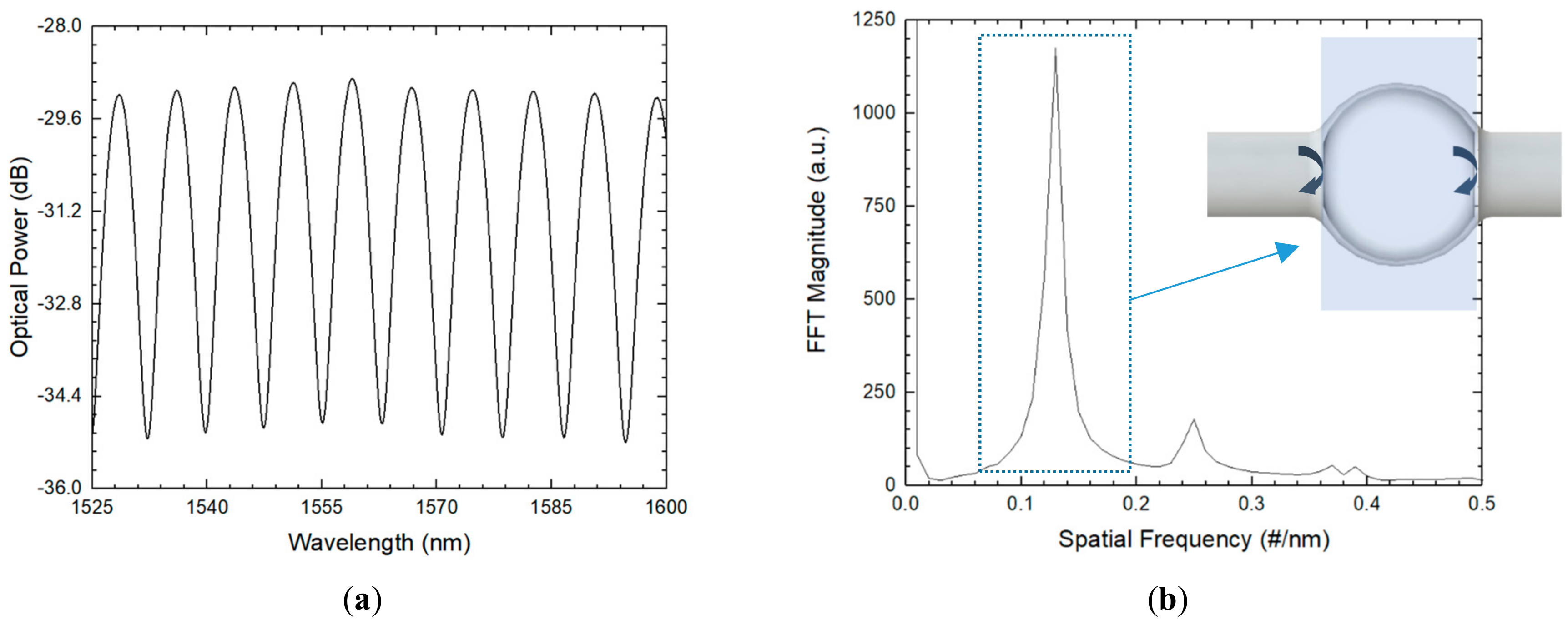
Figure 10.
(a,b) Reflection spectrum of the two studied sensors and (c) schematic diagram of the two-coupled hollow microspheres.
Figure 10.
(a,b) Reflection spectrum of the two studied sensors and (c) schematic diagram of the two-coupled hollow microspheres.


Table 1.
Strain sensitivity comparison between different cavity structures.
| Cavity Structure | Strain Sensitivity | Cavity Size | Reference |
|---|---|---|---|
| Hollow-core photonic bandgap fiber | 1.55 pm/µε | 200 µm | [34] |
| Chemically etched Er-doped fiber | 3.15 pm/µε | 104 µm | [35] |
| Two inline microspheres | 4.07 pm/µε | - | [33] |
| Photonic crystal fiber | 4.50 pm/µε | 75 µm | [36] |
| Inline hollow microsphere | 4.66 pm/µε | 157 µm | [32] |
| Spheroidal microbubble | 10.3 pm/µε | 10 µm | [37] |
© 2018 by the authors. Licensee MDPI, Basel, Switzerland. This article is an open access article distributed under the terms and conditions of the Creative Commons Attribution (CC BY) license (http://creativecommons.org/licenses/by/4.0/).
Share and Cite
MDPI and ACS Style
Gomes, A.D.; Monteiro, C.S.; Silveira, B.; Frazão, O. A Brief Review of New Fiber Microsphere Geometries. Fibers 2018, 6, 48. https://doi.org/10.3390/fib6030048
AMA Style
Gomes AD, Monteiro CS, Silveira B, Frazão O. A Brief Review of New Fiber Microsphere Geometries. Fibers. 2018; 6(3):48. https://doi.org/10.3390/fib6030048
Chicago/Turabian StyleGomes, André Delgado, Catarina Silva Monteiro, Beatriz Silveira, and Orlando Frazão. 2018. "A Brief Review of New Fiber Microsphere Geometries" Fibers 6, no. 3: 48. https://doi.org/10.3390/fib6030048
Note that from the first issue of 2016, this journal uses article numbers instead of page numbers. See further details here.