Geometry of Chalcogenide Negative Curvature Fibers for CO2 Laser Transmission


Abstract
1. Introduction
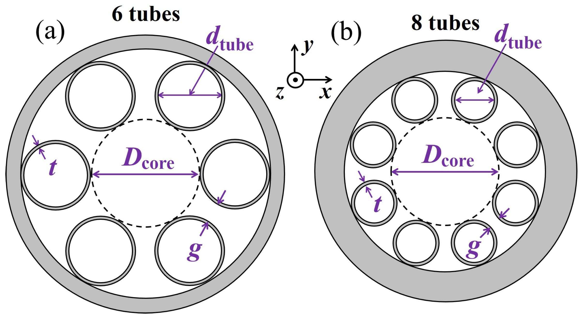
2. Geometry
3. AsSe Chalcogenide Glass
4. AsS Chalcogenide Glass
5. Conclusions
Author Contributions
Funding
Conflicts of Interest
References
- Snakenborg, D.; Klank, H.; Kutter, J.P. Microstructure fabrication with a CO2 laser system. J. Micromech. Microeng. 2004, 14, 182–189. [Google Scholar] [CrossRef]
- Hædersdal, M.; Sakamoto, F.H.; Farinelli, W.A.; Doukas, A.G.; Tam, J.; Anderson, R.R. Fractional CO2 laser-assisted drug delivery. Lasers Surg. Med. 2010, 42, 113–122. [Google Scholar] [CrossRef] [PubMed]
- Witteman, W.J. The CO2 Laser; Enoch, J.F., Macadam, D.L., Schawlow, A.L., Shimoda, K., Tamir, T., Eds.; Springer: Berlin, Germany, 1987; pp. 1–4. ISBN 978-3-540-47744-0. [Google Scholar]
- Poletti, F.; Petrovich, M.N.; Richardson, D.J. Hollow-core photonic bandgap fibers: Technology and applications. Nanophotonics 2013, 2, 315–340. [Google Scholar] [CrossRef]
- Roberts, P.J.; Couny, F.; Sabert, H.; Mangan, B.J.; Williams, D.P.; Farr, L.; Mason, M.W.; Tomlinson, A.; Birks, T.A.; Knight, J.C.; et al. Ultimate low loss of hollow-core photonic crystal fibres. Opt. Express 2005, 13, 236–244. [Google Scholar] [CrossRef] [PubMed]
- Wang, Y.Y.; Couny, F.; Roberts, P.J.; Benabid, F. Low loss broadband transmission in optimized core-shaped Kagome hollow-core PCF. In Proceedings of the Lasers Electro-Optics, Quantum Electron, Laser Science Conference, San Jose, CA, USA, 16–21 May 2010. [Google Scholar]
- Wang, Y.Y.; Wheeler, N.V.; Couny, F.; Roberts, P.J.; Benabid, F. Low loss broadband transmission in hypocycloid-core Kagome hollow-core photonic crystal fiber. Opt. Lett. 2011, 36, 669–671. [Google Scholar] [CrossRef] [PubMed]
- Pryamikov, A.D.; Biriukov, A.S.; Kosolapov, A.F.; Plotnichenko, V.G.; Semjonov, S.L.; Dianov, E.M. Demonstration of a waveguide regime for a silica hollow-core microstructured optical fiber with a negative curvature of the core boundary in the spectral region >3.5 μm. Opt. Express 2011, 19, 1441–1448. [Google Scholar] [CrossRef] [PubMed]
- Yu, F.; Wadsworth, W.J.; Knight, J.C. Low loss silica hollow core fibers for 3–4 μm spectral region. Opt. Express 2012, 20, 11153–11158. [Google Scholar] [CrossRef] [PubMed]
- Wei, C.; Weiblen, R.J.; Menyuk, C.R.; Hu, J. Negative curvature fibers. Adv. Opt. Photon. 2017, 9, 504–561. [Google Scholar] [CrossRef]
- Michieletto, M.; Lyngs, J.K.; Jakobsen, C.; Lgsgaard, J.; Bang, O.; Alkeskjold, T.T. Hollow-core fibers for high power pulse delivery. Opt. Express 2016, 24, 7103–7119. [Google Scholar] [CrossRef] [PubMed]
- Wei, C.; Menyuk, C.R.; Hu, J. Polarization-filtering and polarization-maintaining low-loss negative curvature fibers. Opt. Express 2018, 26, 9528–9540. [Google Scholar] [CrossRef] [PubMed]
- Kosolapov, A.F.; Pryamikov, A.D.; Biriukov, A.S.; Shiryaev, V.S.; Astapovich, M.S.; Snopatin, G.E.; Plotnichenko, V.G.; Churbanov, M.F.; Dianov, E.M. Demonstration of CO2-laser power delivery through chalcogenide glass fiber with negative-curvature hollow core. Opt. Express 2011, 19, 2572–25728. [Google Scholar] [CrossRef] [PubMed]
- Shiryaev, V.S. Chalcogenide glass hollow-core microstructured optical fibers. Front. Mater. 2015, 2, 24. [Google Scholar] [CrossRef]
- Gattass, R.R.; Rhonehouse, D.; Gibson, D.; McClain, C.C.; Thapa, R.; Nguyen, V.Q.; Bayya, S.S.; Weiblen, R.J.; Menyuk, C.R.; Shaw, L.B.; et al. Infrared glass-based negative-curvature anti-resonant fibers fabricated through extrusion. Opt. Express 2016, 14, 25697–25703. [Google Scholar] [CrossRef] [PubMed]
- Wei, C.; Hu, J.; Menyuk, C.R. Comparison of loss in silica and chalcogenide negative curvature fibers as the wavelength varies. Front. Phys. 2016, 4, 30. [Google Scholar] [CrossRef]
- Debord, B.; Amsanpally, A.; Chafer, M.; Baz, A.; Maurel, M.; Blondy, J.M.; Hugonnot, E.; Scol, F.; Vincetti, L.; Gérôme, F.; et al. Ultralow transmission loss in inhibited-coupling guiding hollow fibers. Optica 2017, 4, 209–217. [Google Scholar] [CrossRef]
- Debord, B.; Alharbi, M.; Bradley, T.; Fourcade-Dutin, C.; Wang, Y.Y.; Vincetti, L.; Gérôm, F.; Benabid, F. Hypocycloid-shaped hollow-core photonic crystal fiber Part I: Arc curvature effect on confinement loss. Opt. Express 2013, 21, 28597–28608. [Google Scholar] [CrossRef] [PubMed]
- Yu, F.; Knight, J.C. Negative curvature hollow-core optical fiber. IEEE J. Sel. Top. Quantum Electron. 2016, 22, 4400610. [Google Scholar] [CrossRef]
- Hu, J.; Menyuk, C.R. Understanding leaky modes: Slab waveguide revisited. Adv. Opt. Photonics 2009, 1, 58–106. [Google Scholar] [CrossRef]
- Alagashev, G.K.; Pryamikov, A.D.; Kosolapov, A.F.; Kolyadin, A.N.; Lukovkin, A.Y.; Biriukov, A.S. Impact of geometrical parameters on the optical properties of negative curvature hollow core fibers. Laser Phys. 2015, 25, 055101. [Google Scholar] [CrossRef]
- Poletti, F. Nested antiresonant nodeless hollow core fiber. Opt. Express 2014, 22, 23807–23828. [Google Scholar] [CrossRef] [PubMed]
- Habib, M.S.; Bang, O.; Bache, M. Low-loss hollow-core silica fibers with adjacent nested anti-resonant tubes. Opt. Express 2015, 23, 17394–17406. [Google Scholar] [CrossRef] [PubMed]
- Belardi, W.; Knight, J.C. Hollow antiresonant fibers with reduced attenuation. Opt. Lett. 2014, 39, 1853–1856. [Google Scholar] [CrossRef] [PubMed]
- Kolyadin, A.N.; Kosolapov, A.F.; Pryamikov, A.D.; Biriukov, A.S.; Plotnichenko, V.G.; Dianov, E.M. Light transmission in negative curvature hollow core fiber in extremely high material loss region. Opt. Express 2013, 21, 9514–9519. [Google Scholar] [CrossRef] [PubMed]
- Wei, C.; Menyuk, C.R.; Hu, J. Impact of cladding tubes in chalcogenide negative curvature fibers. IEEE Photonics J. 2016, 8, 2200509. [Google Scholar] [CrossRef]
- Uebel, P.; Günendi, M.C.; Frosz, M.H.; Ahmed, G.; Edavalath, N.N.; Ménard, J.-M.; Russell, P.S.J. Broadband robustly single-mode hollow-core PCF by resonant filtering of higher-order modes. Opt. Lett. 2016, 41, 1961–1964. [Google Scholar] [CrossRef] [PubMed]
- Liu, X.; Ding, W.; Wang, Y.Y.; Gao, S.; Cao, L.; Feng, X.; Wang, P. Characterization of a liquid-filled nodeless anti-resonant fiber for biochemical sensing. Opt. Lett. 2017, 42, 863–866. [Google Scholar] [CrossRef] [PubMed]
- Wei, C.; Menyuk, C.R.; Hu, J. Bending-induced mode non-degeneracy and coupling in chalcogenide negative curvature fibers. Opt. Express 2016, 24, 12228–12239. [Google Scholar] [CrossRef] [PubMed]
- Saitoh, K.; Koshiba, M. Leakage loss and group velocity dispersion in air-core photonic bandgap fibers. Opt. Express 2003, 11, 3100–3109. [Google Scholar] [CrossRef] [PubMed]
- Caillaud, C.; Renversez, G.; Brilland, L.; Mechin, D.; Calvez, L.; Adam, J.-L.; Troles, J. Photonic Bandgap Propagation in All-Solid Chalcogenide Microstructured Optical Fibers. Materials 2014, 7, 6120–6129. [Google Scholar] [CrossRef] [PubMed]
- Wei, C.; Kuis, R.A.; Chenard, F.; Menyuk, C.R.; Hu, J. Higher-order mode suppression in chalcogenide negative curvature fibers. Opt. Express 2015, 23, 15824–15832. [Google Scholar] [CrossRef] [PubMed]
- Belardi, W.; Knight, J.C. Negative curvature fibers with reduced leakage loss. In Proceedings of the Optical Fiber Communication Conference, San Francisco, CA, USA, 9–13 March 2014. [Google Scholar]
- Weiblen, R.J.; Menyuk, C.R.; Gattass, R.R.; Shaw, L.B.; Sanghera, J.S. Fabrication tolerances in As2S3 negative-curvature antiresonant fibers. Opt. Lett. 2016, 41, 2624–2627. [Google Scholar] [CrossRef] [PubMed]
- Hayes, J.R.; Sandoghchi, S.R.; Bradley, T.D.; Liu, Z.; Slavik, R.; Gouveia, M.A.; Wheeler, N.V.; Jasion, G.; Chen, Y.; Fokoua, E.N.; et al. Antiresonant hollow core fiber with an octave spanning bandwidth for short haul data communications. J. Lightw. Technol. 2017, 35, 437–442. [Google Scholar] [CrossRef]


© 2018 by the authors. Licensee MDPI, Basel, Switzerland. This article is an open access article distributed under the terms and conditions of the Creative Commons Attribution (CC BY) license (http://creativecommons.org/licenses/by/4.0/).
Share and Cite
Wei, C.; Menyuk, C.R.; Hu, J. Geometry of Chalcogenide Negative Curvature Fibers for CO2 Laser Transmission. Fibers 2018, 6, 74. https://doi.org/10.3390/fib6040074
Wei C, Menyuk CR, Hu J. Geometry of Chalcogenide Negative Curvature Fibers for CO2 Laser Transmission. Fibers. 2018; 6(4):74. https://doi.org/10.3390/fib6040074
Chicago/Turabian StyleWei, Chengli, Curtis R. Menyuk, and Jonathan Hu. 2018. "Geometry of Chalcogenide Negative Curvature Fibers for CO2 Laser Transmission" Fibers 6, no. 4: 74. https://doi.org/10.3390/fib6040074
APA StyleWei, C., Menyuk, C. R., & Hu, J. (2018). Geometry of Chalcogenide Negative Curvature Fibers for CO2 Laser Transmission. Fibers, 6(4), 74. https://doi.org/10.3390/fib6040074