Flexural Behavior of Carbon Textile-Reinforced Geopolymer Composite Thin Plate
by
 , , , and
Hiep Le Chi
1,* ,
,
Petr Louda
1 ,
,
Aravin Prince Periyasamy
2 ,
,
Totka Bakalova
1 and
Vladimir Kovacic
1 1
Department of Material Science, Faculty of Mechanical Engineering, Technical University of Liberec, Studenstká 2, 461 17 Liberec, Czech Republic
2
Department of Material Engineering, Faculty of Textile Engineering, Technical University of Liberec, Studenstká 2, 461 17 Liberec, Czech Republic
*
Author to whom correspondence should be addressed.
Fibers 2018, 6(4), 87; https://doi.org/10.3390/fib6040087
Submission received: 28 September 2018
/
Revised: 4 November 2018
/
Accepted: 6 November 2018
/
Published: 8 November 2018
Abstract
:Textile-reinforced Portland cement-based concrete has been researched and developed over the last few decades. It was widely used in a different range of applications, such as repair and/or strengthening of structural elements, thin walls, lightweight structures, façade elements, and others. Due to its varied application, this study aims to develop the carbon textile-reinforced geopolymer composite. Specimens of rectangular form with the dimensions of 400 × 100 × 15 mm3, reinforced with carbon textile, were produced. Four-point bending test was used to evaluate the effect of carbon textile on the mechanical strength of reinforced geopolymer composite based on the three factors: the different mortar compositions corresponding to the addition of the chopped basalt fiber (BF), the number of carbon textile layers, and the different thicknesses of the mortar cover layer. Besides that, a small part of the pull-out test was also considered to assess the adhesion strength at the interface between carbon textile and geopolymer mortar. The experimental results from the four-point bending test showed that the mechanical strength of composite specimens increased when the content of the chopped basalt fiber increased. With the increasing number of the textile layers, the specimens improved the flexural strength significantly. However, the flexural toughness of the specimens reinforced with three textile layers did not improve, as compared to those reinforced with two textile layers. The experimental results for the specimens related to the mortar cover thicknesses indicated that specimens with the mortar cover thickness of 2 mm provide the best strength. The experimental results from the pull-out tests showed that all the specimens have the same failure mode by slipping of the fiber yarn from the matrix.
1. Introduction
For many decades now, the ordinary Portland cement-based concrete (PCC) has been most widely used as construction material, due to its outstanding properties, such as high durability, high compressiveness, desired mechanical strength with respect to economic efficiency, ability to be cast into any desired shape, and that its ingredients are available in the most places. Besides this, an inherent disadvantage of PCC is that it contributes to environmental pollution due to CO2 emission in the Portland cement production process. The production of a ton of cement is usually associated with the emission of 0.73 to 0.99 ton of CO2, and the cement industry is one of the major distributions to the global CO2 emissions, where these industries emit approximately 7% of the global share [1,2]. In such a context, the development of innovative new building materials is needed to substitute Portland cement. A new binding material known as geopolymer, developed by Davidovits in 1978, is being considered as a possible substitute to Portland cement [3].
Geopolymers are inorganic aluminosilicate polymers with non-crystalline networks, which are ceramic-like in their structures and properties [4]. Geopolymer materials are synthesized from a two-component blend, including an alkaline solution primarily based on potassium or sodium, and solid aluminosilicate materials based on metakaolin or fly ash at room, or slightly higher, temperature [5,6,7]. The geopolymerization process is the result of the three different stages, consisting of (i) the dissolution of the primary aluminosilicate materials in an alkaline environment with release of silicates and aluminates species, (ii) organization of these species into a growing gel phase, and (iii) condensation of the gel phase to shape a stable 3D structure [8,9]. Several superior properties of geopolymer materials include its high compressive strength [10], excellent stability in a variety of chemical environments [11,12,13], good thermal stability [14], high fire resistance [15], and others. Moreover, the manufacturing of the raw materials for geopolymers produces only a fraction of the CO2 emissions compared to Portland cement. For the above such advantages, it can be stated that geopolymers have drawn more attention as a promising building material. Nonetheless, regarding pure geopolymer, its brittle nature, like most ceramics, make it difficult to be accepted as an engineering material. Pure geopolymers are very sensitive to crack formation under loading. Cracks continue to propagate as the load increases; as a result, geopolymers fail when faced with extra loads [16]. Consequently, geopolymers should exist in the system of the multi-component materials by means of the addition of a variety of reinforcements into them, to form a geopolymer composite with improved mechanical properties and structures. In this regard, fiber-reinforcement plays a vital role in overcoming its low tensile and flexural strengths. Due to the possibility of random distribution after addition to geopolymer, fibers can be linked to the cracks and capture their evolution. Hence, the mechanical properties of the geopolymer are improved. Also, the particle-reinforced geopolymer provides several advantages, particularly as it offers desirable material properties while geopolymer resin acts as a binding intermediate essential for structural applications. Zhang [17] reported the using of hollow glass microsphere waste and quartz powder to enhance compressive strength and sulfuric acid resistance of fly ash/slag-based geopolymers. Duan [18] presented the impact of the use of silica fume on mechanical properties and microstructure of fly ash-based geopolymer beneath thermal cycle. The results obtained in each study showed the distinct strengths of each type of reinforcement for each application range. Due to the easy association with reinforcements, geopolymers bring forward an economically helpful substitute to Portland cement concrete. Their possible applications include as fireproof materials [15,19,20], thermal insulation [21,22,23], thermal shock refractories [24], lightweight materials [25,26,27], foams [28,29,30], etc.
Textile-reinforced concrete (TRC) is a new type of building composite material with respect to non-corrosive textile reinforcement [31] as steel-reinforced bars. Compared to conventional steel-reinforced concrete, TRC composite does not require a strong covering layer to protect against the corrosion during the lifetime of the structure. This composite also proves the enhanced strength in tensile and ductility. Thus, the concrete structural elements will become slender, lighter, and more flexible. Textile-reinforced concrete can be utilized in a wide range of applications, such as the lightweight concrete systems [32,33,34], repairing and/or strengthening in current structural elements [35,36], thin wall elements [37,38], etc. In another context, the research and development of non-corrosion textile material, reinforced in Portland cement concrete for the different applications, have been studied by many researchers, however, with respect to the geopolymer, this is quite a new field. There are a restricted number of studies on the assessment of textile reinforcements for the strengthening purpose of geopolymer concrete. Tamburini [39] performed an experiment on the use of geopolymer grout combined with different types of textile for the strengthening of brick masonry substrates. Shaikh [40] investigated an experiment on the combined effect of AR-glass textile and polyvinyl alcohol (PVA) fiber on the four-point behavior of geopolymer composites. Menna [41] studied the use of geopolymers, instead of polymeric resins, along with fibers for composite external reinforcement of existing reinforced concrete structural members. For the motivation of expanding developed opportunities and the design of advanced geopolymer composite materials, this paper presents information about the production of the thin plate composites, based on geopolymer mortar reinforced with the carbon textile, to assess their mechanical strength through four-point bending strength. In addition, a small part of the pull-out test is performed to evaluate the adhesion strength at the interface between geopolymer matrix and carbon fiber yarn. Geopolymer mortar matrix is a mixture of sodium based geopolymer resin, fine-grain silica sand, and various contents of chopped basalt fiber (BF).
2. Materials and Methods
2.1. Materials
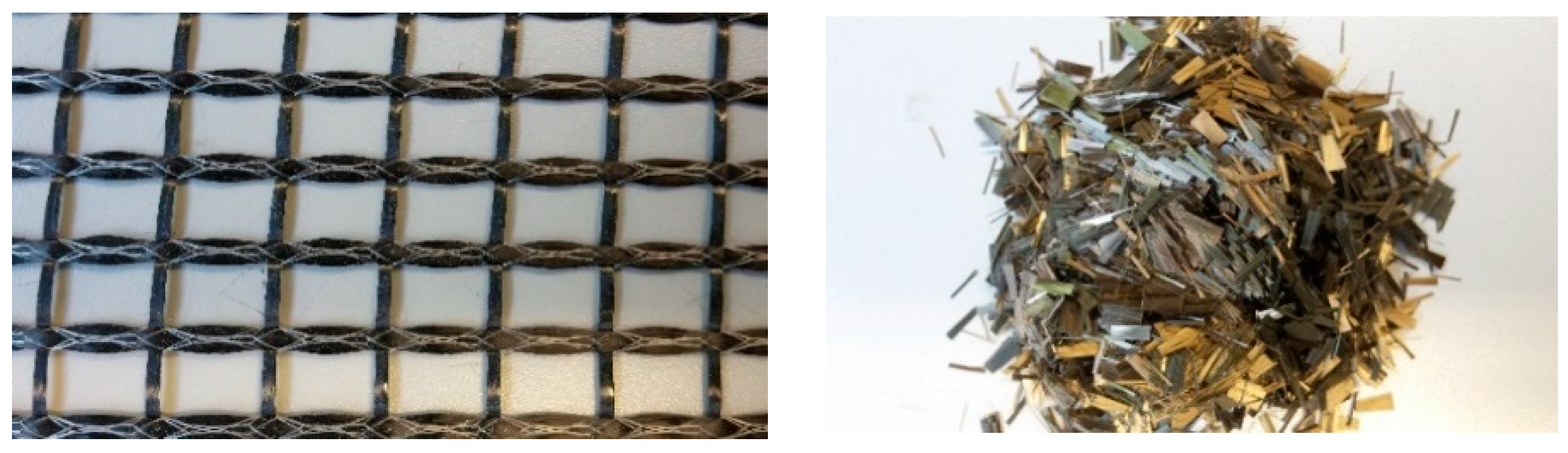
Geopolymer binder, based on metakaolin, was used as the aluminosilicate source for producing geopolymer mortar (in weight percent: SiO2—47.4; Al2O3—29.7; CaO—14.5; MgO—2.6; TiO2—1.8; Fe2O3—0.5; K2O—0.3; Na2O—1) along with sodium silicate activator of modul 1.73 (in weight percent: SiO2—20.72; Na2O—12.33; H2O—66.68). Geopolymer cement was synthesized from calcined kaolin and shale fly dust burnt in a rotary kiln (for 10 h at 750 °C) with a Si/Al molar ratio of 2.0. Two different types of silica sand were used as the fine aggregates for geopolymer mortar matrix (grain size in mm: 0–0.063 and 0.6–1.25). The chopped basalt fiber (BF) was provided by Kamenny Vek, and the tows were 6.4 mm long with individual fiber diameters of 13 µm, a density of 2.67 g/cm3, tensile strength in the range of 2700–3200 MPa, and tensile modulus of 85–95 GPa, as shown in Figure 1. Basalt has a softening and melting point of 1060 °C and 1250 °C, respectively. It is non-combustible, making it useful for high-temperature applications. The silane coating or sizing helps to protect the brittle fibers from premature fracture, and prevents them from binding each other. In this work, BF addition with various percentage contents of 3%, 5%, and 7.5% (by weight of geopolymer resin) was considered. A carbon textile of net size 14 × 10 mm was provided by Frisiverto S.R.O company, Czech Republic, as shown in Figure 1. The carbon grid was made up of 48 K individual filaments for the yarns in the longitudinal direction, and 12 K individual filaments for the yarns in the transverse direction, and a density of 1.8 g/cm3. The yarns of carbon textile were arranged in two orthogonal directions (0/90°) to form a textile grid, and they were coated using a styrene–butadiene binder. Further detailed properties are shown in Table 1. In the four-point bending test of geopolymer composite specimens, carbon textiles were placed in the molds such that the force acting on the specimen was in the longitudinal direction of the yarn.
2.2. Specimen Manufacturing
2.2.1. Geopolymer Mortar Matrix Preparation
Geopolymer mortar matrix was prepared according to the following steps. Pure geopolymer resin was a two-part blend from geopolymer cement and sodium silicate activator, which was prepared in a ratio of geopolymer cement to activator (1:0.8). This mixture was mechanically stirred for approximately 5 min to ensure a homogenous fresh paste. After that, microsilica sand was added into the prepared paste and stirred for around 3 min more. Finally, chopped basalt fiber (with various percentage content for each mixture) together with the rough silica sand were added into the prepared mixture, followed by mechanical mixing for a few minutes to ensure homogeneous distribution of the BF in the mortar matrix. The detailed proportion of mixture was shown in Table 2. The fresh mortar was cast into 30 × 30 × 150 mm3 prismatic molds for the flexural and compressive test. Three samples for each mixture were used for flexural test, and then the compressive strength was measured on both residual pieces obtained from flexural strength according to EN 196-1 standard [42].
2.2.2. Specimen Preparation for the Four-Point Flexural Test
For the four-point bending test, the samples are molded in the rectangular form with the dimensions of 400 × 100 × 15 mm3. Carbon textile was used as reinforced with geopolymer mortar, and the specimen was prepared with a hand lay-up method, and the alignment of carbon textile in the mold was clearly described in Figure 2. Four-point bending test for the specimens was performed on the three different types. In the first type, the effect of chopped basalt fiber on the bending strength of specimens was analyzed. Therefore, the different mortar compositions based on the various percentage contents of the BF and one carbon textile layer were used. In the second type, the effect of the number of carbon textile layers on the bending strength of the specimens was analyzed. Geopolymer mortar matrix without BF addition, and one to three textile layers were used. In the last type, the effect of the different thicknesses of the mortar cover layer was analyzed. The one textile layer, geopolymer mortar matrix containing 5% BF, and the mortar cover thicknesses of 2, 4, and 6 mm, were used to produce the specimens.
2.2.3. Specimen Preparation for the Pull-Out Test
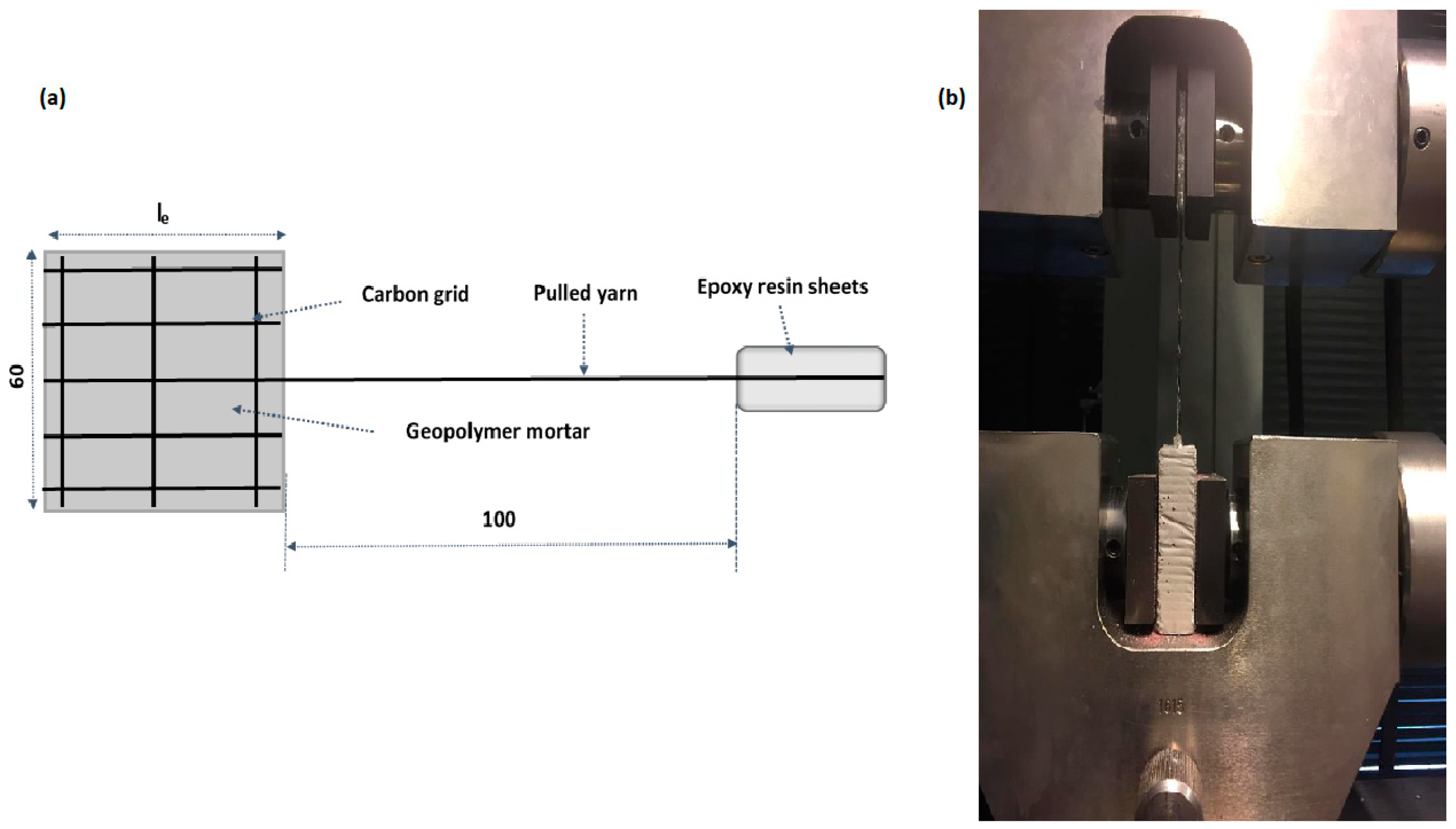
Pull-out tests were performed for the specimens with the dimensions of 20 × 60 mm2, and the three different embedded lengths (le): 50, 75, and 100 mm. Only a geopolymer mortar matrix containing 5% BF was chosen to carry out the pull-out test. It should be made clear that the mortar containing 5% BF satisfies two conditions, as compared to those containing the other BF contents: (i) mortar mixing and casting of specimens is easy; (ii) high mechanical strength of the hardened mortar. Although the mortar containing 7.5% BF shows the best mechanical strength, it takes more time to mix and cast.
Single fiber yarn in carbon grid was embedded in the middle of specimens, along with the whole length. The free length (yarn part at the out of the mortar matrix) was 100 mm, constant for all the specimens, and its end was glued by epoxy resin sheets for loading (see Figure 3a).
2.2.4. Curing Regime and Curing Time
After casting, all the specimens were wrapped using a polypropylene film, and cured at room temperature, ~26 °C, with 65% relative humidity for 24 h. Afterwards, the specimens were demolded, and wrapped again using a polypropylene film, and kept at room temperature until testing. Three specimens for each mixture were prepared. They were tested at approximately 28 days after the casting.
2.3. Four-Point Bending Test and Pull-Out Test Setup
Four-point bending test, with a constant support span of 100 mm, was used to determine the bending strength of the specimens. The detailed description about the specimen arrangement and testing process was shown in Figure 4. The testing machine with load cell capacity of 100 kN (FP Lab Test II, from LABORTECH s.r.o Opava, Czech Republic), located at the Technical University of Liberec Laboratory, with the applied load under displacement control at a loading rate of 2 mm/min, was used. The four-point flexural strength can be calculated as per the Equation (1):
where σ is the four-point flexural strength in MPa; F is the load at a given point on the load–displacement curve in N; b is the width of the tested sample in mm; h is the thickness of the sample in mm; and l is the support span in mm.
σ = Fl/(bh2),
For the pull-out test, the specimens were clamped on the special device of the universal testing machine, see Figure 3b. The load was applied at the rate 2 mm/min, and increased gradually until the yarn was pulled out from the geopolymer matrix. The testing ended when the applied load was reduced to 95%, or the cross-head displacement of the testing machine was maximum, about 10 mm. The bond strength was calculated using the following equations:
where τm is the bond strength in MPa; Fmax is the peak pull-out load in N; d is the fiber diameter in mm; l is the embedded length in mm; and Df is the fiber density in g/cm3.
τm = Fmax/(πdl),
As = Tex/Df = (πd2)/4,
3. Results and Discussion
3.1. The Mechanical Strength of Geopolymer Mortar Matrix
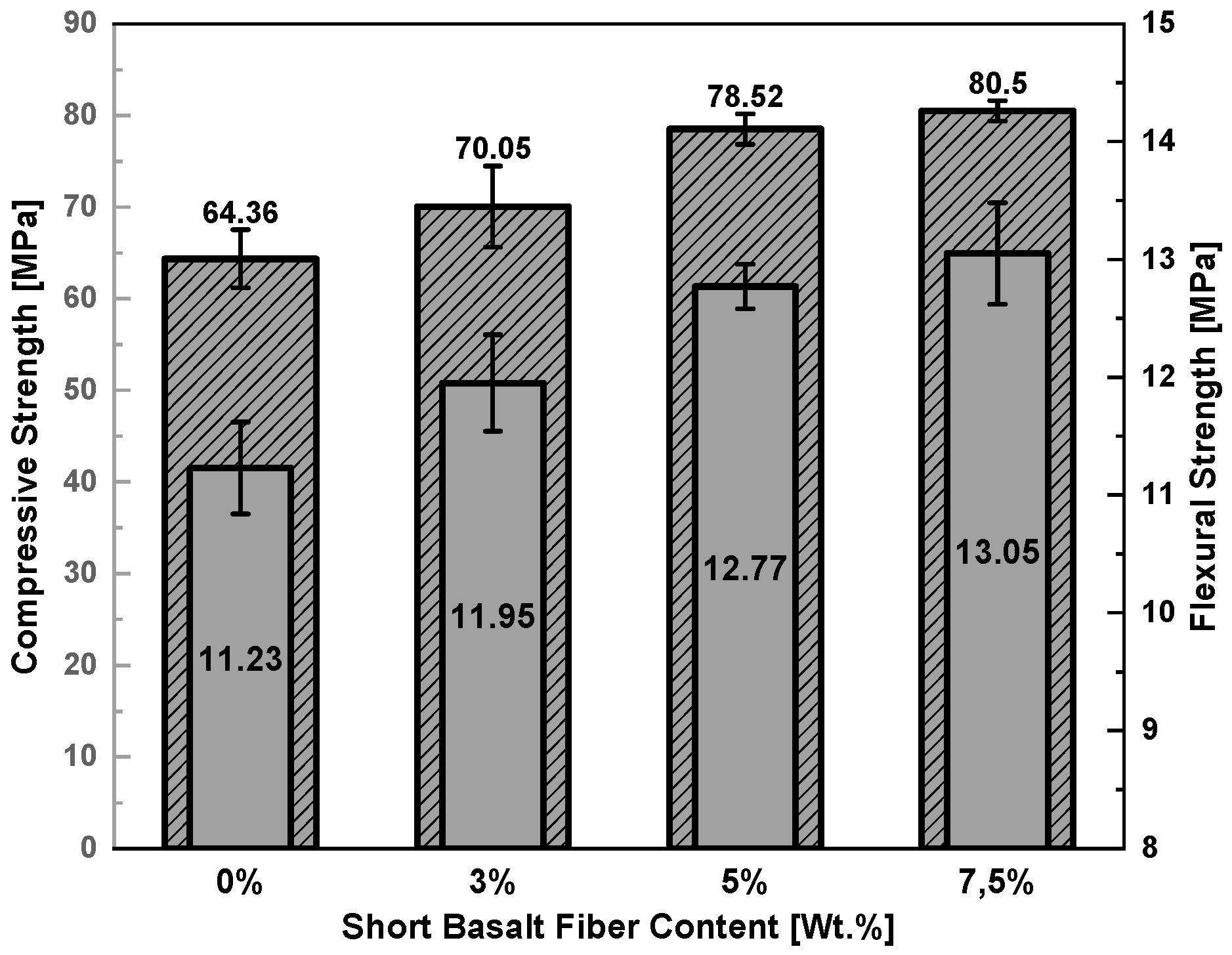
Figure 5 provides information about the results of the average flexural and compressive strength of geopolymer mortar matrix at the age of 28 days. Overall, both mechanical strengths show an upward trend with increasing BF content. On the other hand, when BF content goes up from 0% to 3%, and 3% to 5%, the specimens show a significant increase in strength, however, when BF content increases from 5% to 7.5%, the slight rate of strength increase is observed. The average mechanical strength of the specimens without BF addition is 11.23 MPa in flexural and 64.36 MPa in compressive strength. The average strength of the specimens with the addition of 3%, 5%, and 7.5% BF increases the flexural strength by 6.40%, 13.71%, and 16.21%, respectively, whereas compressive strength increases by 8.84%, 22%, and 25.08%, respectively, as compared to specimens without BF addition.
3.2. Pull-Out Behavior
In this section, the pull-out test is carried out to characterize the adhesion strength between carbon fiber yarn and geopolymer matrix. The good bond strength at the interface between yarn and matrix can cause breakage of the yarn at the initiation time of the first crack. On the contrary, the low bond strength means easily pulling out of the textile. The bond strength may be considered as a dominating factor for the mechanical properties of textile-reinforced geopolymer composite.
Figure 6a shows the experimental results of the pull-out curves of all the specimens. In general, pull-out tests consist of three different phases: first, the elongation of the yarn free length (yarn part not embedded) along with elastic adhesion between fiber yarn and matrix, followed by formation of debonding phase. The debonding phase continues to increase until reaching the pull-out peak load, and a significant drop in load happens. The load drop represents the transition from debonding phase, which is controlled by both chemical bond and frictional bond to the pull-out phase with frictional bond only. After debonding of the fiber/matrix interface is finished, the chemical bond does not survive, but the frictional bond continues to remain constant, and the load tends to decrease [43]. The pull-out load increases with increasing embedded length. The specimens with the embedded lengths of 75 mm and 100 mm, increase by 22.31% and 72.37%, respectively, compared to specimens with the embedded length of 50 mm, as seen in Figure 6b. The experimental results show that the average interfacial bond stress decreases when increasing the embedded length of fiber yarn. For this reason, it can be explained by the longer the embedded length of fiber yarn in the matrix, where it is more difficult to unify distribution of bond stress over the entire embedded length; as a result, the maximum average bond stress at failure will be smaller [44].
3.3. Flexural Behavior of Carbon Textile-Reinforced Geopolymer Composites
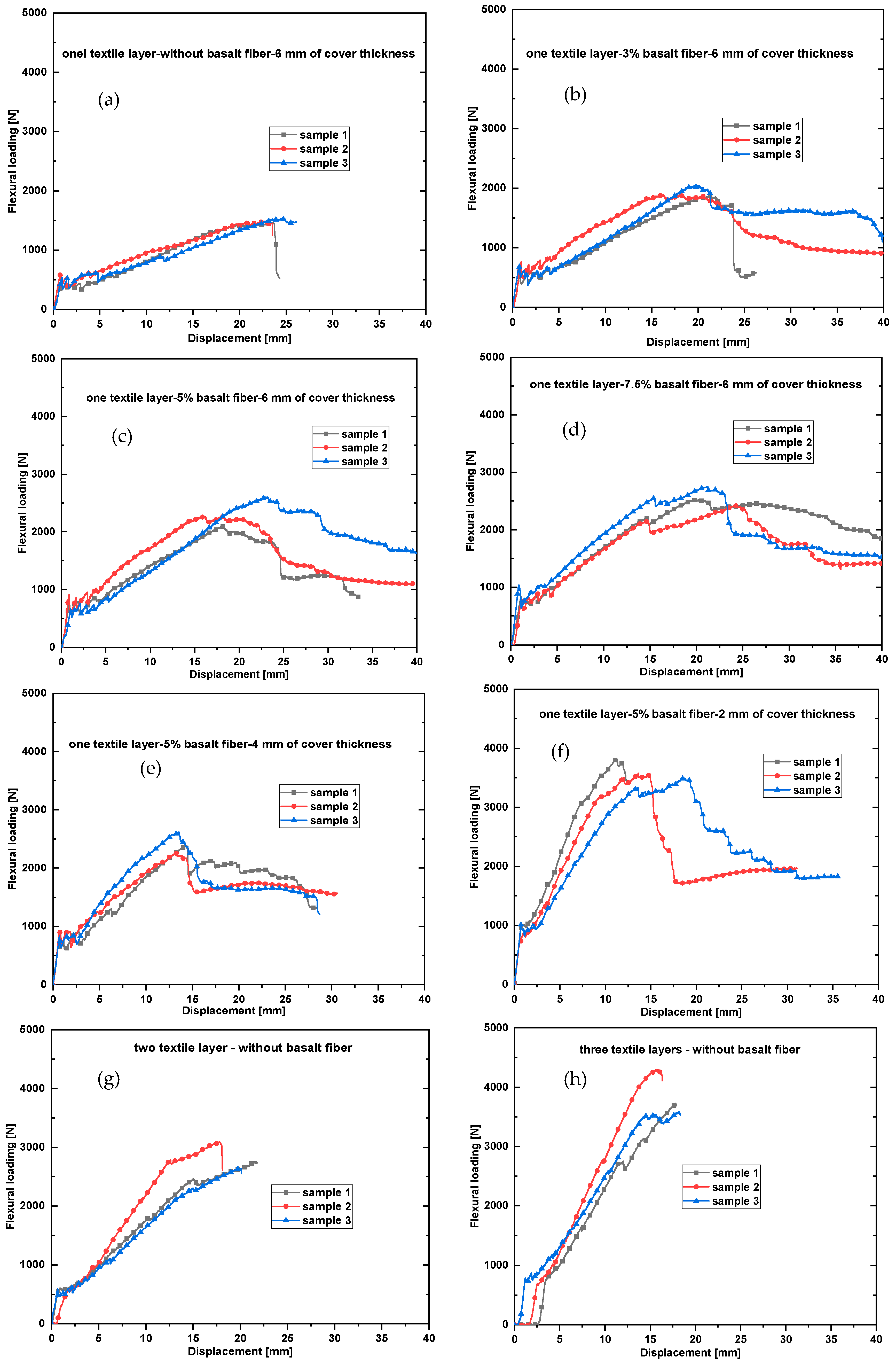
In this section, the influence of the different contents of the chopped basalt fiber, the number of the textile layers, and the different thicknesses of the mortar cover layer on the bending behavior of the specimens will be discussed. Figure 7a–h presents the bending load–displacement curves of all the specimens, whereas Table 3 summarizes the average values of the experimental results that include the first-crack load, first-crack stress, ultimate load, ultimate stress, ultimate displacement, and flexural toughness. Toughness is the ability of the composite materials, which indicates how much energy it can absorb before rupturing. Toughness value is calculated as the area under the respective load–displacement curves up to the peak load of each specimen. Overall, the flexural load–displacement curves of all the specimens indicate the similar behavior. It consists of the three parts corresponding to the stages in the flexural test. Three behavior areas are clearly visible during the bending test. The first stage describes the load-bearing geopolymer matrix, as shown by the linear increase in load until the formation of the first crack happens. The slope of this segment of the curve reflects the stiffness of the geopolymer matrix. In the second stage is the formation of the multi-cracks, as proven through the oscillation of the loading curve, when the load continues to apply. In this stage, it seems that the structure of textile/geopolymer matrix composite is being reorganized with the compromise between matrix and textile reinforcement, for the purpose of the composite that can continue to take its higher load-bearing capacity. It can be said that the number of cracks in each specimen almost results in this stage, and the figure of this segment of the curve depends significantly on the number of textile layers, the organization of carbon textile in geopolymer matrix, the stiffness of geopolymer matrix, and the adhesion strength at the interface between fiber yarn and matrix. The last stage is the process of expanding of all cracks that formed in the second stage. Moreover, it is also considered that there could appear some new cracks. The current cracks continue to become broader until the specimens break down by rupturing or slipping of the fiber yarns of the textile.
The influence of the different BF contents on the flexural behavior of the specimens is described in Figure 7a–d, whereas Figure 8 and Table 3 summarize the mean values of the first-crack load, first-crack stress, ultimate load, ultimate stresses, ultimate displacement, and flexural toughness of the corresponding specimens. It can be seen that the BF-reinforced geopolymer mortar is useful to enhance both first-crack load and the ultimate load of the textile-reinforced specimens. It can be observed by fact that chopped fiber adds to accelerating the early age performance of the geopolymer mortar; as a result, it can conduce the restricted appearance of micro-cracks in geopolymer mortar. Moreover, the connection between fiber yarns of the textile and geopolymer mortar is also promoted due to the bridge effect of the chopped fiber at the micro-cracks. In this case, it could be said that the chopped fiber contributes to enhance the efficiency of the textile in reinforcement as well. The BF-reinforced geopolymer composites confirm the high-quality advancement in the aspect of the bending strength and, the higher the fiber content, the higher the bending strength when compared to geopolymer composites without BF addition. The average ultimate strength of the specimens without BF addition is 21.59 MPa. The average ultimate strength of the specimens with BF addition of 3%, 5%, and 7.5 increases by approximately 23.76%, 38.90%, and 58.59%, respectively, compared to those without BF addition. The specimens also increase in the flexural toughness with the increasing BF content. The average flexural toughness of the specimens without BF addition is 21.03 kN.mm. The average flexural toughness of the specimens with BF addition of 3%, 5%, and 7.5%, increases by 12.89%, 32.81%, and 73.04%, respectively, compared to those without BF addition.
Figure 7c,e,f shows the influence of the different mortar cover thicknesses on the flexural behavior of the specimens. The mean values of the experimental results are represented in Table 3 and Figure 9. It can be observed from Figure 9 that the thin cover layer leads to an increment of tension element (textile layer) that brings higher stiffness and higher bearing capacity. This phenomenon can be explained by the fact that when the cover layer thickness guarantees the anchoring capability of the textile in the matrix, the specimens with thinner cover layer will delay the development of the crack width as long as possible, due to the tension efficiency of the textile. This results in both geopolymer mortar and textile undergoing collectively better bearing capacity under loading. It can be seen that, in comparison with the specimens having cover thickness of 6 mm, the ultimate stress of the specimens having a cover thickness of 4 mm and 2 mm, increases by 4.1% and 59.12%, respectively (see in Figure 9). With a slight increase of flexural strength, on the other hand, there is a significant reduction in displacement of the specimens which have the mortar cover thickness of 4 mm, which also provides the lowest toughness value as compared to the other specimens.
The influence of the number of the textile layers on the flexural behavior of the specimens is illustrated in Figure 7a,g,h. The mean values of the experimental results are represented in Table 3 and Figure 10. In comparison with the one textile layer reinforced specimens, the two textile layer reinforced specimens increase in the first-crack stress by 28.87%, in the ultimate stress by 68.64%, and in the toughness by 56.30%. The three textile layer reinforced specimens increase in the first-crack stress by 73.08%, in the ultimate stress by 118.64%, and in the toughness by 53.83% (see in Table 3). It could be observed that the three textile layer reinforced specimens increase significantly in ultimate stress by 29.66%, but decrease in toughness by 1.6%, compared to two textile layer reinforced specimens.
Figure 11 shows the failure modes of the several specimens, which are represented for the common failure modes of all the specimens after finishing of the bending test. Figure 11a,b shows the failure mode of one to three textile layer reinforced specimens without BF addition. During the destruction phase of the specimens under loading, a gradual peeling process of the fiber yarns occurs out from the matrix, followed by collapsing of the geopolymer matrix, due to reaching the maximum load. On the contrary, in the specimens containing the high BF content, the interfacial debonding between the matrix and the textile does not occur, as seen clearly in Figure 11c,d. The failure mode of these specimens controls the flexural failure by slipping of the fiber yarns from the geopolymer matrix. It can be clearly shown in Figure 12 that after finishing the pull-out test, all the specimens show the same failure by slipping of fiber yarn from the matrix and, in this case, there is no impact on the specimen length.
4. Conclusions
The flexural behavior of carbon textile-reinforced specimens is based on three different factors: (i) the different mortar compositions corresponding to BF addition; (ii) number of textile layers; and (iii) thicknesses of the mortar cover layer, which were investigated and discussed. Besides that, the pull-out test was also performed to provide information about adhesion strength between carbon fiber yarn and geopolymer matrix. Based on the results achieved, the following conclusions were drawn:
- When BF is added into geopolymer mortar, the experimental results showed that the mechanical strength of the thin plate specimens improved significantly; and the mechanical strength increased with increasing BF content.
- In comparison with the one textile layer reinforced specimens, reinforcement with two to three textile layers significantly improves the flexural strength and toughness. However, the three textile layer reinforced specimens do not have an increase in flexural toughness, as compared to those reinforced with two textile layers.
- The specimens with the mortar cover layer of 2 mm provide the best result in both flexural stress and toughness.
- The experimental results from the pull-out test show that the average interfacial bond stress decreased with increasing embedded length of the fiber yarn. For this reason, it can be explained by that, the longer the embedded length of fiber yarn in the matrix, the more difficult for the unified distribution of bond stress over the whole embedded length. As a result, the average maximum bond stress will be smaller. After finishing the pull-out test, all the specimens show the same failure by slipping of the fiber yarn from the matrix and, in this case, there is no impact on the specimen length.
Author Contributions
H.L.C. designed and performed the experiments and wrote the paper; P.L. supervision; A.P.P. reviewed and edited the final paper; T.B. reviewed the final paper; V.K. assisted the experiment process.
Funding
This work was supported by Institutional Endowment for the Long Term Conceptual Development of Research Institutes, as provided by the Ministry of Education, Youth and Sports of the Czech Republic in the year 2018 and by the project “Application of geopolymer composites as fire, AGK“, registration number VI20172019055, were obtained through the financial support of the Ministry of interior in the program “The Safety Research of the Czech Republic” 2015-2020 (BV III/1-VS).
Acknowledgments
First author is acknowledged to the Technical University of Liberec, Faculty of Mechanical Engineering and Ministry of Education, Youth and Sports, Czech Republic for providing the fund and facilities to write this paper.
Conflicts of Interest
The authors declare no conflict of interest.
References
- Verian, K.P.; Behnood, A. Effects of deicers on the performance of concrete pavements containing air-cooled blast furnace slag and supplementary cementitious materials. Cem. Concr. Compos. 2018, 90, 27–41. [Google Scholar] [CrossRef]
- Meyer, C. The greening of the concrete industry. Cem. Concr. Compos. 2009, 31, 601–605. [Google Scholar] [CrossRef]
- Davidovits, P.J. Properties of Geopolymer Cements. In Proceedings of the First International Conference on Alkaline Cements and Concretes Scientific, Kiev, Ukraine, 11–14 October 1994; pp. 131–149. [Google Scholar]
- Davidovits, J. Geopolymers: Ceramic-like inorganic polymers. J. Ceram. Sci. Technol. 2017, 8, 335–350. [Google Scholar] [CrossRef]
- Wang, M.R.; Jia, D.C.; He, P.G.; Zhou, Y. Microstructural and mechanical characterization of fly ash cenosphere/metakaolin-based geopolymeric composites. Ceram. Int. 2011, 37, 1661–1666. [Google Scholar] [CrossRef]
- Bernal, S.A.; Rodríguez, E.D.; Mejía De Gutiérrez, R.; Gordillo, M.; Provis, J.L. Mechanical and thermal characterisation of geopolymers based on silicate-activated metakaolin/slag blends. J. Mater. Sci. 2011, 46, 5477–5486. [Google Scholar] [CrossRef]
- Zhang, Z.; Wang, H.; Zhu, Y.; Reid, A.; Provis, J.L.; Bullen, F. Using fly ash to partially substitute metakaolin in geopolymer synthesis. Appl. Clay Sci. 2014, 88–89, 194–201. [Google Scholar] [CrossRef]
- Wan, Q.; Rao, F.; Song, S.; García, R.E.; Estrella, R.M.; Patino, C.L.; Zhang, Y. Geopolymerization reaction, microstructure and simulation of metakaolin-based geopolymers at extended Si/Al ratios. Cem. Concr. Compos. 2017, 79, 45–52. [Google Scholar] [CrossRef]
- Yao, X.; Zhang, Z.; Zhu, H.; Chen, Y. Geopolymerization process of alkali-metakaolinite characterized by isothermal calorimetry. Thermochim. Acta 2009, 493, 49–54. [Google Scholar] [CrossRef]
- Yuan, J.; He, P.; Jia, D.; Yang, C.; Zhang, Y.; Yan, S.; Yang, Z.; Duan, X.; Wang, S.; Zhou, Y. Effect of curing temperature and SiO2/K2O molar ratio on the performance of metakaolin-based geopolymers. Ceram. Int. 2016, 42, 16184–16190. [Google Scholar] [CrossRef]
- Salhi, K.; Mezghiche, B. Evaluation of the mechanical properties and durability of cement mortars containing algerian metakaolin. Ceram. Silikaty 2017, 61, 65–73. [Google Scholar] [CrossRef]
- Allahverdi, A.; Škvára, F. Sulfuric acid attack on hardened paste of geopolymer cements Part 2. Corrosion mechanism at mild and relatively low concentrations. Ceram. Silikaty 2006, 50, 1–4. [Google Scholar] [CrossRef]
- Allahverdi, A. Sulfuric Acid Attack on Hardened Paste of Geopolymer Cements Part 2. Corrosion Mechanism at Mild and Relatively Low Concentrations. Ceram. Silikaty 2005, 4, 3–6. [Google Scholar]
- Zheng, K.; Chen, L.; Gbozee, M. Thermal stability of geopolymers used as supporting materials for TiO2 film coating through sol-gel process: Feasibility and improvement. Constr. Build. Mater. 2016, 125, 1114–1126. [Google Scholar] [CrossRef]
- Sarker, P.K.; Kelly, S.; Yao, Z. Effect of fire exposure on cracking, spalling and residual strength of fly ash geopolymer concrete. Mater. Des. 2014, 63, 584–592. [Google Scholar] [CrossRef]
- Pan, Z.; Sanjayan, J.G.; Rangan, B.V. Fracture properties of geopolymer paste and concrete. Mag. Concr. Res. 2011, 63, 763–771. [Google Scholar] [CrossRef] [Green Version]
- Zhang, W.; Yao, X.; Yang, T.; Liu, C.; Zhang, Z. Increasing mechanical strength and acid resistance of geopolymers by incorporating different siliceous materials. Constr. Build. Mater. 2018, 175, 411–421. [Google Scholar] [CrossRef]
- Duan, P.; Yan, C.; Zhou, W. Compressive strength and microstructure of fly ash based geopolymer blended with silica fume under thermal cycle. Cem. Concr. Compos. 2017, 78, 108–119. [Google Scholar] [CrossRef]
- Roviello, G.; Ricciotti, L.; Ferone, C.; Colangelo, F.; Tarallo, O. Fire resistant melamine based organic-geopolymer hybrid composites. Cem. Concr. Compos. 2015, 59, 89–99. [Google Scholar] [CrossRef]
- Lyon, R.E.; Balaguru, P.N.; Foden, A.; Sorathia, U.; Davidovits, J.; Davidovics, M. Fire-resistant aluminosilicate composites. Fire Mater. 1997, 21, 67–73. [Google Scholar] [CrossRef]
- Temuujin, J.; Minjigmaa, A.; Rickard, W.; Lee, M.; Williams, I.; van Riessen, A. Preparation of metakaolin based geopolymer coatings on metal substrates as thermal barriers. Appl. Clay Sci. 2009, 46, 265–270. [Google Scholar] [CrossRef]
- Temuujin, J.; Rickard, W.; Lee, M.; Van Riessen, A. Preparation and thermal properties of fire resistant metakaolin-based geopolymer-type coatings. J. Non Cryst. Solids 2011, 357, 1399–1404. [Google Scholar] [CrossRef]
- Temuujin, J.; Minjigmaa, A.; Rickard, W.; Lee, M.; Williams, I.; van Riessen, A. Fly ash based geopolymer thin coatings on metal substrates and its thermal evaluation. J. Hazard Mater. 2010, 180, 748–752. [Google Scholar] [CrossRef] [PubMed]
- Timakul, P.; Rattanaprasit, W.; Aungkavattana, P. Enhancement of compressive strength and thermal shock resistance of fly ash-based geopolymer composites. Constr. Build. Mater. 2016, 121, 653–658. [Google Scholar] [CrossRef]
- Rickard, W.D.A.; Gluth, G.J.G.; Pistol, K. In-situ thermo-mechanical testing of fly ash geopolymer concretes made with quartz and expanded clay aggregates. Cem. Concr. Res. 2016, 80, 33–43. [Google Scholar] [CrossRef]
- Torres, M.L.; GARCÍA-RUIZ, P.A. Lightweight pozzolanic materials used in mortars: Evaluation of their influence on density, mechanical strength and water absorption. Cem. Concr. Compos. 2009, 31, 114–119. [Google Scholar] [CrossRef]
- Medri, V.; Papa, E.; Mazzocchi, M.; Laghi, L.; Morganti, M.; Francisconi, J.; Landi, E. Production and characterization of lightweight vermiculite/geopolymer-based panels. Mater. Des. 2015, 85, 266–274. [Google Scholar] [CrossRef]
- Rickard, W.D.A.; Van Riessen, A. Performance of solid and cellular structured fly ash geopolymers exposed to a simulated fire. Cem. Concr. Compos. 2014, 48, 75–82. [Google Scholar] [CrossRef]
- Masi, G.; Rickard, W.D.A.; Vickers, L.; Bignozzi, M.C.; Van Riessen, A. A comparison between different foaming methods for the synthesis of light weight geopolymers. Ceram. Int. 2014, 40, 13891–13902. [Google Scholar] [CrossRef]
- Feng, J.; Zhang, R.; Gong, L.; Li, Y.; Cao, W.; Cheng, X. Development of porous fly ash-based geopolymer with low thermal conductivity. Mater. Des. 2015, 65, 529–533. [Google Scholar] [CrossRef]
- Williams Portal, N.; Flansbjer, M.; Johannesson, P.; Malaga, K.; Lundgren, K. Tensile behaviour of textile reinforcement under accelerated ageing conditions. J. Build. Eng. 2016, 5, 57–66. [Google Scholar] [CrossRef]
- Williams Portal, N.; Flansbjer, M.; Zandi, K.; Wlasak, L.; Malaga, K. Bending behaviour of novel Textile Reinforced Concrete-foamed concrete (TRC-FC) sandwich elements. Compos. Struct. 2017, 177, 104–118. [Google Scholar] [CrossRef]
- Colombo, I.G.; Colombo, M.; Di Prisco, M. Bending behaviour of Textile Reinforced Concrete sandwich beams. Constr. Build. Mater. 2015, 95, 675–685. [Google Scholar] [CrossRef]
- Dey, V.; Zani, G.; Colombo, M.; Di Prisco, M.; Mobasher, B. Flexural impact response of textile-reinforced aerated concrete sandwich panels. Mater. Des. 2015, 86, 187–197. [Google Scholar] [CrossRef]
- Mechtcherine, V. Novel cement-based composites for the strengthening and repair of concrete structures. Constr. Build. Mater. 2013, 41, 365–373. [Google Scholar] [CrossRef]
- Jabr, A.; El-Ragaby, A.; Ghrib, F. Effect of the Fiber Type and Axial Stiffness of FRCM on the Flexural Strengthening of RC Beams. Fibers 2017, 5, 2. [Google Scholar] [CrossRef]
- Naaman, A.E. Evolution in Ferrocement and Thin Reinforced Cementitious Composites. Arab. J. Sci. Eng. 2012, 37, 421–441. [Google Scholar] [CrossRef]
- Williams Portal, N.; Nyholm Thrane, L.; Lundgren, K. Flexural behaviour of textile reinforced concrete composites: Experimental and numerical evaluation. Mater. Struct. Constr. 2017, 50, 1–14. [Google Scholar] [CrossRef]
- Tamburini, S.; Natali, M.; Garbin, E.; Panizza, M.; Favaro, M.; Valluzzi, M.R. Geopolymer matrix for fibre reinforced composites aimed at strengthening masonry structures. Constr. Build. Mater. 2017, 141, 542–552. [Google Scholar] [CrossRef]
- Uddin, F.; Shaikh, A. Flexural Behavior of Hybrid PVA Fiber and AR-Glass Textile Reinforced Geopolymer Composites. Fibers 2018, 6, 2. [Google Scholar] [CrossRef]
- Menna, C.; Asprone, D.; Ferone, C.; Colangelo, F.; Balsamo, A.; Prota, A.; Cioffi, R.; Manfredi, G. Use of geopolymers for composite external reinforcement of RC members. Compos. Part B Eng. 2013, 45, 1667–1676. [Google Scholar] [CrossRef]
- BS EN. Methods of Testing Cement—Part 1: Determination of Strength; European Committee for Standardization: Brussels, Belgium, 2005; Volume 169, p. 36. [Google Scholar]
- Aljewifi, H.; Zhang, X.B.; Li, J. Analysis on Pull-Out Behaviour of Continuous Multi-Filament Glass Yarns Embedded in Cementitious Matrix by Using a Developed Model. In Proceedings of the 11th International Symposium on Ferrocement and 3rd ICTRC Texttile Reinforced Concrete, Aachen, Germany, 7–10 June 2015. [Google Scholar]
- Yin, S.; Wang, B.; Wang, F.; Xu, S. Bond investigation of hybrid textile with self-compacting fine-grain concrete. J. Ind. Text. 2017, 46, 1616–1632. [Google Scholar] [CrossRef]
Figure 1.
Carbon textile and chopped basalt fiber used in this work.

Figure 2.
Schematic drawing for the arrangement of carbon textile in the specimens (unit: mm).

Figure 3.
Schematic drawing for specimen preparation (a); image of pull-out test performance (b).

Figure 4.
Four-point bending test for the thin plate specimens.

Figure 5.
The flexural strength (gray plot) and compressive strength (striped plot) of geopolymer mortar matrix at 28 days.
Figure 5.
The flexural strength (gray plot) and compressive strength (striped plot) of geopolymer mortar matrix at 28 days.

Figure 6.
Results of the pull-out test: (a) Load–displacement curves of the fiber yarn embedded geopolymer matrix; (b) the average values of the pull-out load and the average values of the pull-out stress.
Figure 6.
Results of the pull-out test: (a) Load–displacement curves of the fiber yarn embedded geopolymer matrix; (b) the average values of the pull-out load and the average values of the pull-out stress.

Figure 7.
The flexural load–displacement curves of the thin plate specimens: (a) one textile layer reinforced specimens without BF addition and the mortar cover thickness of 6 mm; (b) one textile layer reinforced specimens containing 3% BF and the mortar cover thickness of 6 mm; (c) one textile layer reinforced specimens containing 5% BF and the mortar cover thickness of 6 mm; (d) one textile layer reinforced specimens containing 7.5% BF and the mortar cover thickness of 6 mm; (e) one textile layer reinforced specimens containing 5% BF, and the cover mortar thickness of 4 mm; (f) one textile layer reinforced specimens containing 5% BF and the mortar cover thickness of 2 mm; (g) two textile layer reinforced specimens without BF addition; (h) three textile layer reinforced specimens without BF addition.

Figure 8.
The mechanical strength of one textile layer reinforced specimens with the different BF contents of 0%, 3%, 5%, 7.5%: (a) flexural stress; (b) flexural toughness.
Figure 8.
The mechanical strength of one textile layer reinforced specimens with the different BF contents of 0%, 3%, 5%, 7.5%: (a) flexural stress; (b) flexural toughness.

Figure 9.
The mechanical strength of one textile layer reinforced specimens containing 5% BF with respect to the mortar cover thicknesses: (a) flexural stress; (b) flexural toughness.
Figure 9.
The mechanical strength of one textile layer reinforced specimens containing 5% BF with respect to the mortar cover thicknesses: (a) flexural stress; (b) flexural toughness.

Figure 10.
The mechanical strength of one to three textile layer reinforced specimens without BF addition: (a) flexural stress; (b) flexural toughness.
Figure 10.
The mechanical strength of one to three textile layer reinforced specimens without BF addition: (a) flexural stress; (b) flexural toughness.

Figure 11.
Failure modes of the textile reinforced specimens: (a) one textile layer reinforced specimens without BF addition; (b) three textile layer reinforced specimens without BF addition; (c) one textile layer reinforced specimens containing 5% BF; (d) one textile layer reinforced specimens containing 7.5% BF.

Figure 12.
The specimens after pull-out tests.


Table 1.
Properties of carbon textile.
| Form | Carbon Fiber Grid |
|---|---|
| Fiber type | Carbon fiber 10/15–40 |
| Binder yarn | PP 110dtex |
| Fiber construction | Fiber orientation 0/90° (bi-directional) |
| Tex | 800 g/km |
| Fiber density | 1.8 g/cm3 |
| Number of threads/m | 78 (lengthways) and 55 (crossways) |
| weight | 350 g/m2 |
| Coating | Styrene-butadiene |
| Stitch spacing | 10 × 15 mm (center to center distance) |
| Tensile strength | 2551 N/mm2 (lengthways) and 2847 N/mm2 (crossways) |
| Elongation lengthways | 1.17% |
| Elongation crossways | 1.24% |
Table 2.
Mixture of geopolymer mortar matrix.
| BF Content (wt % of Geopolymer Resin) | By Weight Ratio (–) | |||
|---|---|---|---|---|
| Geopolymer Cement | Activator | Microsand | Rough-Sand | |
| 0, 3, 5, 7.5 | 1 | 0.8 | 0.2 | 1.5 |
Table 3.
Results of the flexural behavior of the thin plate specimens with respect to the different percentage contents of the BF, the number of textile layers, and the thicknesses of the mortar cover layer.
Table 3.
Results of the flexural behavior of the thin plate specimens with respect to the different percentage contents of the BF, the number of textile layers, and the thicknesses of the mortar cover layer.
| Specimen | The Average Value (Standard Deviation) | |||||
|---|---|---|---|---|---|---|
| First-Crack Load (kN) | First-Crack Stress (MPa) | Ultimate Load (kN) | Ultimate Stress (MPa) | Ultimate Displacement (mm) | Flexural Toughness (kN.mm) | |
| 1 layer + 0%BF | 0.42 (0.07) | 5.61 (1.16) | 1.62 (0.52) | 21.59 (2.12) | 18.94 (2.42) | 21.03 (1.56) |
| 1 layer + 3% BF | 0.68 (0.11) | 9.02 (1.60) | 2.05 (0.40) | 26.72 (4.07) | 18.01 (2.93) | 23.74 (2.99) |
| 1 layer + 5% BF | 0.78 (0.06) | 10.38 (0.79) | 2.25 (0.31) | 29.99 (4.11) | 20.03 (2.61) | 27.93 (5.90) |
| 1 layer + 7.5% BF | 0.88 (0.11) | 11.78 (1.40) | 2.57 (0.14) | 34.24 (1.88) | 21.85 (1.83) | 36.39 (4.51) |
| 1 layer + 0%BF | 0.42 (0.07) | 5.61 (1.16) | 1.62 (0.52) | 21.59 (2.12) | 18.94 (2.42) | 21.03 (1.56) |
| 2 layers + 0%BF | 0.54 (0.04) | 7.23 (0.47) | 2.73 (0.32) | 36.41 (4.32) | 19.98 (1.79) | 32.87 (0.56) |
| 3 layers + 0%BF | 0.73 (0.02) | 9.71 (0.22) | 3.54 (0.55) | 47.21 (7.40) | 15.23 (1.77) | 32.35 (1.84) |
| 2 mm + 5% BF | 0.90 (0.11) | 12.02 (1.52) | 3.58 (0.25) | 47.72 (3.35) | 14.56 (3.72) | 33.19 (8.05) |
| 4 mm + 5% BF | 0.79 (0.11) | 10.52 (1.52) | 2.34 (0.41) | 31.23 (5.51) | 13.68 (0.60) | 19.85 (3.27) |
| 6 mm + 5% BF | 0.78 (0.06) | 10.38 (0.79) | 2.25 (0.31) | 29.99 (4.11) | 20.03 (2.61) | 27.93 (5.90) |
© 2018 by the authors. Licensee MDPI, Basel, Switzerland. This article is an open access article distributed under the terms and conditions of the Creative Commons Attribution (CC BY) license (http://creativecommons.org/licenses/by/4.0/).
Share and Cite
MDPI and ACS Style
Le Chi, H.; Louda, P.; Periyasamy, A.P.; Bakalova, T.; Kovacic, V. Flexural Behavior of Carbon Textile-Reinforced Geopolymer Composite Thin Plate. Fibers 2018, 6, 87. https://doi.org/10.3390/fib6040087
AMA Style
Le Chi H, Louda P, Periyasamy AP, Bakalova T, Kovacic V. Flexural Behavior of Carbon Textile-Reinforced Geopolymer Composite Thin Plate. Fibers. 2018; 6(4):87. https://doi.org/10.3390/fib6040087
Chicago/Turabian StyleLe Chi, Hiep, Petr Louda, Aravin Prince Periyasamy, Totka Bakalova, and Vladimir Kovacic. 2018. "Flexural Behavior of Carbon Textile-Reinforced Geopolymer Composite Thin Plate" Fibers 6, no. 4: 87. https://doi.org/10.3390/fib6040087
Note that from the first issue of 2016, this journal uses article numbers instead of page numbers. See further details here.