Electrically Conductive Coatings for Fiber-Based E-Textiles


Department of Textile Engineering, Chemistry and Science, Wilson College of Textiles, North Carolina State University, Raleigh, NC 27606, USA
*
Author to whom correspondence should be addressed.
Fibers 2019, 7(6), 51; https://doi.org/10.3390/fib7060051
Submission received: 26 March 2019
/
Revised: 17 May 2019
/
Accepted: 22 May 2019
/
Published: 1 June 2019
(This article belongs to the Special Issue Smart Coatings on Fibers and Textiles)
Abstract
:With the advent of wearable electronic devices in our daily lives, there is a need for soft, flexible, and conformable devices that can provide electronic capabilities without sacrificing comfort. Electronic textiles (e-textiles) combine electronic capabilities of devices such as sensors, actuators, energy harvesting and storage devices, and communication devices with the comfort and conformability of conventional textiles. An important method to fabricate such devices is by coating conventionally used fibers and yarns with electrically conductive materials to create flexible capacitors, resistors, transistors, batteries, and circuits. Textiles constitute an obvious choice for deployment of such flexible electronic components due to their inherent conformability, strength, and stability. Coating a layer of electrically conducting material onto the textile can impart electronic capabilities to the base material in a facile manner. Such a coating can be done at any of the hierarchical levels of the textile structure, i.e., at the fiber, yarn, or fabric level. This review focuses on various electrically conducting materials and methods used for coating e-textile devices, as well as the different configurations that can be obtained from such coatings, creating a smart textile-based system.
1. Introduction
In recent years, electronic textiles (e-textiles) as a class of soft or flexible electronics have generated a growing interest due to their many potential applications in healthcare, security, entertainment, and others. E-textile systems are produced through the integration of various electrical devices, such as sensors [1,2,3], transistors [4,5,6,7], communication devices [8,9,10], energy harvesting and storage devices [11,12,13,14], and actuators [15,16,17,18], with textiles. As a hierarchical structure, textiles offer unique opportunities to integrate electrical functionalities at various levels—from fibers, yarns, to the finished product [19] (see Figure 1). While electronic capabilities can be integrated into any of these hierarchical levels, the integration of electrically conductive materials at the fiber level arguably enables the most seamlessly-integrated e-textile products. Fiber level integration of electrical capabilities is more likely to help retain the intrinsic textile characteristics of strength, flexibility, durability, comfort, etc., enhance the functionality by enabling communication, as well as sense and respond to the external environment [20].
To achieve this goal of unobtrusive integration of electronics with textiles, it is important to use materials and methods that can impart the necessary electrical conductivity to a textile fiber. Electrical conductivity at the fiber level can be achieved by using either intrinsically conducting polymers (ICPs) in forming the fiber or by coating conventional insulating fibers with conducting materials [21]. Various materials such as ICPs [22,23], conducting polymer composites [24,25], metals [21,26], and carbon based materials, such as carbon nanotubes [27,28], carbon nanopowders [1] and graphene [29,30], have been used to achieve this. These materials have been applied using coating methods such as electro- and electroless deposition [31,32,33], dip-coating [34,35], and chemical vapor deposition (CVD) [23,30] to achieve such electrically conductive e-textile coatings. The electrically conductive coated fibers can be used in a variety of applications in e-textiles. However, we limit the scope of this review to cover one of the most explored areas in e-textiles—the fiber-based sensors [25,26,27]. A sensor is a device that can respond to an external stimulus by generating a measurable signal. Fiber-based sensing devices have been proposed for many applications, such as biomedical monitoring [22,28], security [29], sports [30], and others [24,36,37]. Such sensors are flexible, lightweight, conformable, and can be woven or knitted into various textile structures for facile integration of sensors within the fabric structure [19]. In principle, fiber-based sensors can be designed to operate using many of the principles of sensing, such as capacitive, resistive, piezoelectric, etc., to detect various stimuli such as pressure, strain, proximity, and temperature [28].
In this review, electronic capabilities integrated into the fiber-based sensors via any of the coating processes are explored. The first section explores the materials that have been commonly used for imparting such electrical conductivity to e-textile fibers, including ICPs, conducting polymer composites, metals, and carbon nanotube-based coatings, as well as the methods that have been employed to apply these coatings conformably onto the fibers. The following section covers types of coated fiber-based sensors classified based on their sensing principle as well as their performance and applications. While fibers and yarns differ considerably in textile processing, in this review, both fiber and yarn-based sensors are included.
2. Materials and Methods Used for Coating
Coating fibers or yarns with electrically conductive materials offers the inherent advantage of providing a route to transform already manufactured textile materials into electrically conductive e-textiles. This eliminates the need to add electrical functionality during fiber manufacturing, which many electrically conductive materials may not be compatible with [38]. Moreover, due to the various coating methods available, a variety of materials can be incorporated into the fiber without the limitation of using conventional textile processing techniques [39]. Coating processes also enable the incorporation of materials into e-textiles that cannot themselves form fiber, yarn, or fabric structures, such as ICPs, which are mechanically too weak to withstand various textile processes [39]. The subsequent sections explore the various materials and methods that have been used to render e-textile fibers conductive, with emphasis on limiting the discussion to fibers and yarn structures rather than complete fabrics.
2.1. Intrinsically Conducting Polymers (ICPs)
Research into ICPs began in 1974, when Shirakawa et al. first reported electrically conductive films composed of polyacetylene made via the polymerization of acetylene with 1000 times higher amounts of catalyst than usual [40]. ICPs can be classified as either cation or anion salts of highly conjugated polymer structures. The cation salts can be formed via electrochemical polymerization or chemical oxidation, whereas the less stable anion salts can be formed via electrochemical reduction or by using reagents [41]. While ICPs are generally semiconductors in their pristine state, they can be made more conductive by doping using either p- or n-dopants. Dopant molecules are introduced to add or remove electrons from the backbone of ICPs, resulting in increased conductivity of these polymers. ICPs do, however, have high redox activity and electron affinity, unlike conventional polymers [42]. The charge transport properties of ICPs depend on the packing of their polymer chains and their degree of order, and on the amount of impurities and structural defects present within the structure. In the case of polyacetylene—the simplest linear conjugated ICP—the conductivity is due to the strong interchain interaction, resulting in a fibrillar crystal structure consisting of π-stacked polymer chains. Moreover, due to the π-conjugation, ICPs such as polyacetylene possess a planar structure attributed to the sp2 hybridization of the carbon atoms in the polymer chain, which can be modified by the introduction of dopants [43]. Other than polyacetylene, some of the most important classes of ICPs are polyparaphenylene vinylenes, polyethylene dioxythiophenes, polypyrroles (PPy), and polyaniline (PANI). Figure 2 shows the various ICPs as well as their band gap values (energy difference between the top of the valence band and the bottom of the conduction band).
Since ICPs can be synthesized precisely in a controlled manner with tunable conductivity due to doping, and they have a variety of electrically, structural, and optical properties, they are promising materials for use in various flexible electronics applications [43]. However, due to their rigid backbone structure, which inhibits their solubility as well as their tendency to decompose at temperatures lower than their melting points, most ICPs cannot be melt processed via conventional textile methods [43]. Hence, using ICPs as coatings for e-textile applications is a viable technique to combine the unique properties of these materials with the flexibility, the strength, and the drapability of textiles [45]. Dip-coating is a facile method of applying ICPs onto textile fibers without damaging them in the process. Without the need for specialized equipment, it is an accessible process for making electrically conductive yarns—as long as the ICPs are obtainable in a solution form [46]. Kim et al. explored the formation of electrically conductive polyethylene terephthalate (PET) yarns using dip-coating to apply PANI onto these yarns [47]. PANI was converted into a conductive solution by functionalizing with dodecylbenzene sulfonic acid (DBSA). The proton in the acid reacts with the imine in the PANI, resulting in its protonation and rendering it conductive. The organic group within PANI is compatible with xylene, thereby forming a solution of DBSA-doped solution in xylene. PET yarns were then dip-coated in this solution in a coagulation bath to allow an electrically conductive coating to form on the yarns. This is possible due to the tendency of PANI to spontaneously agglomerate into film-like structures when exposed to a solid/solution interface during the coating process. The resistances of these yarns varied from 103–106 Ω, much higher than those obtained for conductive fibers made by melt spinning of polypropylene (PP) with PPy, which was attributed to the problems of structural inhomogeneity due to the melt spinning process. Moreover, coated yarns were able to better retain their original strength and flexibility.
Mostafalu et al. also used dip-coating to apply conductive PANI ink (along with other inks that were carbon nanopowder based or a composite of carbon nanopowders/PANI) onto cotton threads by sequentially passing these through multiple coating baths, with the ability to process many meters of thread via this process [48], as shown in Figure 3. Dryers were used after coating cycles to adhere the coating to the yarns, and these were subsequently collected on rotating spools, as shown in Figure 3a. PANI was able to form a three-dimensional (3D) network of nanofibers on the cotton yarns (Figure 3d). This enabled enhanced mechanical flexibility of the cotton yarn and more robust coating. These PANI coated cotton yarns were then used as pH sensor electrodes due to the biocompatibility offered by PANI and its high electrical conductivity. However, it is important to note that, while dip-coating is a relatively easy method, it does have certain limitations in terms of the uniformity of the conductive coating thickness, as well as the surface roughness and the agglomeration of conductive particles on the yarns. The latter can cause significant problems for electrical conduction and may even result in electrical discharge at these charge concentration zones [46]. Hence, a more conformal, controllable, and uniform method of applying ICPs as coatings is necessary for long-term, sustainable performance of e-textiles.
To overcome the challenges of dip-coating, alternative approaches such as in-situ polymerization have been explored to deposit ICPs onto textiles [45]. This process involves the physical adsorption of the ICP onto the surface of the textile, followed by polymerization along the plane of the solid–liquid interface to produce a thin, uniform coating that adheres to the fiber surface [49]. Yue et al. explored this technique by coating nylon-lycra fibers by depositing PPy onto the textile fabric substrate with an oxidant and a dopant to enable polymerization of the monomer. This formed conformal PPy coatings on all the fibers with a surface resistance of 149 Ω/square [50]. Interestingly, Yue et al. observed an initial slight increase and a subsequent decrease in resistance with increasing strain. This was attributed to the slow strain recovery of the nylon-lycra fabric at large elongations (50–100%), as well as the type of PPy formed using the specific dopants and the reaction conditions [50]. While this is an example of a fabric-based coating, it still involves the coating of individual fibers via in-situ polymerization. Hence, depending on the construction of the textile as well as the conditions used for polymerization, the electrical performance of ICPs can be tailored to fit the requirements of the sensing system. Sarvi et al. utilized this method to create conductive PANI coatings on multi-walled carbon nanotubes (MWNTs), forming MWNT-PANI core-shell nanofibers that were subsequently used as conductive nanofillers to enable conduction between poly(vinylidene fluoride) (PVDF) nanofibers [51]. PANI enables a better dispersion of MWNTs and enables the formation of conductive bridges between the PVDF fibers. Moreover, since the PVDF nanofibers are subsequently electrospun to form a conductive mat, it is important to form conductive links using the PANI-MWNT network, since air gaps between uncoated PVDF nanofibers prevent the formation of a conductive mat.
Eom et al. developed fiber based strain sensors using poly(3,4-ethylenedioxythiophene (PEDOT) coated polyester (PS) fiber by directly polymerizing the (3,4-ethylenedioxythiophene (EDOT) monomer to form the PEDOT coating [52], as shown in Figure 4. By making a monomer and an oxidant solution and then dipping the PS fiber into it for 20 min at 70 °C, they were able to produce a coated fiber with low resistance. Moreover, a poly(methyl methacrylate) (PMMA) coating was also added to the fiber to enable mechanical robustness and prevent the coating from damaging. In this manner, a PEDOT thickness of 100–300 nm was achieved with an electrical resistance of 600 Ω/cm. While the Young’s modulus of the coated fiber was slightly higher, the overall mechanical behavior was comparable to uncoated PS fibers (Figure 4c). These yarns were subsequently used as strain sensors as knitted fabrics with interlocking insulating PS fibers to hold them in place (Figure 4e,f). The performance of these sensors is further discussed in Section 3.3.1. However, this technique does have certain limitations in terms of the inability to control the mass of coating formed during the in-situ polymerization reaction, problems such as delamination occurring after coating [52], as well as the speed with which the process proceeds. Moreover, due to its use of acidic oxidants and radical cations, this technique can also be harsh on the fabric substrates themselves—in some cases by dissolving the underlying yarn of fiber structure and resulting in film-like substrates [53].
Vapor phase deposition (VPD) techniques such as CVD can combine the synthesis of the ICP and the deposition onto the textile substrate into a single step process without affecting the intrinsic drapability and the mechanical strength of the textile substrate [54,55]. In the CVD technique, a substrate is treated with an oxidant and then exposed to a monomer vapor, which subsequently polymerizes into a coating. This is followed by rinsing with a solvent such as methanol to remove unreacted monomers and any residual oxidants or byproducts [56]. Vapor deposition techniques can be divided into two types depending on the polymerization technique used to form the subsequent ICP film: (i) chain-growth polymerization methods, which include CVD, plasma-enhanced CVD (PECVD), initiated CVD (iCVD), and photoinitiated CVD (piCVD), and (ii) step-growth polymerization methods, which include oxidative CVD (oCVD) and the conventional vapor phase deposition (VPP) method [55]. VPD techniques enable the formation of a conformal coating by supplying monomers to the substrate’s surface in the vapor phase, with the monomer self-initiating or introducing a second initiating species into the polymerization process to form a polymer film. The rate of this technique can be controlled by decreasing the substrate temperature in cases of ICPs and other polymeric films, thereby making this technique suitable for textile substrates that are temperature sensitive [55].
Bashir et al. studied the deposition of PEDOT on viscose and polyester yarns to form conductive fibers using oCVD to deposit the PEDOT [23,56], as shown in Figure 5. By increasing the amount of oxidant (FeCl3) concentration, they were able to obtain conductive, thick PEDOT coatings on the viscose fibers (Figure 5e–i), but this also decreased the tenacity of the viscose fibers. Hence, to overcome this challenge of reduced mechanical properties, PET was explored as an alternative substrate for oCVD of PEDOT, especially due to its mechanical properties and its chemical stability to acidic environments (as presented by the FeCl3 oxidant) compared to viscose fibers. PEDOT coated PET fibers exhibited increased electrical conductivity coupled with better mechanical properties than PEDOT coated viscose fibers, thereby enabling the formation of highly conductive fibers that retain their mechanical properties [32]. VPD techniques offer various advantages for ICPs, such as substrate independent deposition, conformable coatings, low temperature processing, and using ICPs that are difficult to process in solution form. However, the ability to scale up the organic VPD is still being explored, since most commercial VPD processes are designed for inorganic materials, which require high temperatures, input powers, and are incompatible with fragile organic components [55]. Nevertheless, research is being carried out in the field of scalability of organic systems VPD with batch reactors that can coat larger (>1 m) substrate areas [54,55]. The challenge still remains in terms of ensuring uniform deposition of the monomers and the oxidants on such large substrates [56,57].
Different coating processes can result in a variety of coating thicknesses, morphologies, and electrical performances of the ICP coated textile fiber or yarn. Moreover, as fibers are converted to yarns and fabrics, they experience various stresses and strains that are unique to textile processing techniques. Additionally, if they are converted into sensors for commercial use, they would again be subjected to consumer use, such as laundering, shear stresses, and friction forces. Moreover, the coating process itself can add additional stress and can influence the mechanical properties of the fiber. Therefore, the harshness of catalysts, oxidants, and additives used during coating is important to consider. All these factors have to be taken into account while coating fibers with ICPs. As research in the field of ICPs grows and many interesting properties are achieved, there will be a need to consider the various requirements that textiles have and to ensure that a stable coated e-textile can be created [46].
2.2. Carbon Based Coatings
While the last section talked about a special class of polymers that are electrically conductive, most commonly used polymers are considered insulating materials. Within the area of e-textile sensors, various applications can subject the fiber sensor to large amounts of external stresses, which ICP coatings may not be able to withstand [58]. Hence, it is important to be able to convert commonly used polymers into robust electrically conductive systems. This can be done by adding electrically conductive filler materials, such as metal powders, fibers, carbon black (CB), carbon nanotubes (CNTs), and graphene, to the polymer matrix [59,60]. The mechanism of electrical conduction of such a system is based on percolation theory, which correlates the volume of filler material with the amount needed to create an electrically conductive pathway within the polymer matrix [61]. The first significant decrease in the electrical resistivity of the polymer composite is attributed to the formation of infinitely long contact chains between the conducting particles. The volume fraction of the conducting particles within the insulating matrix at which this decrease is first observed is known as the percolation threshold of that matrix and filler system [59]. As the volume fraction of conducting particles is increased beyond the percolation threshold, the resistivity continually decreases up to a certain volume fraction, beyond which continued addition does not cause a large decrease in the resistivity of the composite [61]. Hence, the percolation threshold is the lowest amount of filler concentration required within the polymer matrix to form an electrically conductive pathway [59]. There are a variety of factors that can be attributed to the conduction of electrons through a conductive polymer matrix—percolation theory, quantum mechanical tunneling, and thermal expansion [59]. Tunneling is significant at low temperatures and occurs when a high enough electric field is applied to excite electrons such that they can jump through the potential barrier—making resistivity a function of temperature and voltage. Thermal expansion occurs at high temperatures and causes the polymer matrix to swell, thereby increasing the distance between the particles within the matrix and resulting in an increase in resistivity. To realize conductive fibers and yarns for sensing applications, it is important to apply a composite coating that has good electrical performance as well as stability.
2.2.1. Carbon Nanotubes
CNTs have proven to be excellent candidates for the preparation of conducting polymer composites due to their unique structure coupled with excellent physical and chemical properties as well as mechanical strength [62]. CNTs are cylindrical structures composed of one (single walled CNT or SWNTs) or multiple (multiwalled CNT or MWNTs) layers of graphene with either open or closed ends [63]. With diameters ranging from 0.8–2 nm (SWNTs) and 5–20 nm (MWNTs) and lengths from <100 nm to several centimeters, CNTs can exist at multiple length scales [60], as shown in Figure 6. With the ability to achieve bulk conductivities of approximately 105 S/cm, CNTs are excellent materials to form conductive polymer composites, as their conductivity is within the polymer matrix following the percolation theory as described previously in this section [64]. In most cases, the percolation threshold for CNT-polymer composites is approximately 0.1 wt.%, with percolation thresholds below 0.1 wt.% attributed to systems with kinetic thresholds, where the filler particles can move and reposition themselves due to effects such as convection, diffusion, shearing, or externally applied fields [65]. This enables them to be good candidates for flexible coatings, since they do not require large amounts of filler to be electrically conductive [66]. Moreover, since CNTs themselves possess a high aspect ratio [60], this also has an effect on the percolation behavior of these composites. For statistical percolation, where the movement of filler particles themselves is ignored, the percolation threshold has been observed to decrease with increasing CNT length [67], whereas the electrical conductivity is highest when the CNTs are partially or slightly aligned rather than perfectly aligned and isotropic within the polymer matrix [68].
While CNTs themselves have been using in yarn form for strain sensing due to the observed increase in electrical resistance of CNT yarns with applied tensile strain [72], researchers such as Han et al. have integrated CNTs onto yarns by forming conformal coatings using CNT inks [58]. CNT inks were prepared by dispersing SWNTs into deionized water using sodium dodecylbenzene sulfonate (SDBS) as a surfactant. This dispersion was then coated onto cotton yarns using a paint brush, followed by air drying and washing to remove residual surfactant. Due to the large van der Waals forces between the CNT and the cellulose, as well as the multiple hydrogen bonds formed between the hydroxyl groups in the cellulose and the carboxyl and the hydroxyl end groups within the CNTs, the coating was able to percolate within the cotton yarns, resulting in a resistance of 7.8 kΩ/cm. These yarns were then used as ammonia sensors with a detection limit of 8 ppm and sensitivity ranging from 0–3% depending on the amount of time the sensor yarns were exposed to ammonia [58]. Shim et al. also developed cotton yarns with SWNT and MWNT coatings for use as e-textile biosensors, using the general dip-coating method to coat individual yarns with a dispersion of CNTs in Nafion solution [35]. They observed that the SWNT coated cotton yarns were more conductive (25 Ω/cm) than those coated with MWNT (118 Ω/cm), attributed to the tighter, more dispersed network formed by SWNTs compared to the larger and more rigid network formed by MWNTs on the same cotton substrate. Moreover, they also observed that post processing treatments such as thermal annealing could further reduce the resistance to 19 Ω/cm for the SWNT coated cotton yarns [35].
While these works involve coating CNTs directly onto fibers from dispersion, researchers have also prepared composites containing CNTs that are then coated onto textile yarns. Zhang et al. coated spandex multifilament yarns with a thermoplastic polyurethane (TPU)/CNT coating to form conductive elastic yarns that could act as strain sensors [66], as shown in Figure 7a–e. The yarn was driven over rollers into a TPU/MWNT composite bath where it was coated, followed by hot air drying, and finally coated yarns were collected on a rotating drum (Figure 7a). This process enables coating longer lengths of yarns continuously; however, there were some irregularities in the coating due to agglomeration of CNTs at certain locations on the yarn surface. Moreover, once a continuous coating was formed (at concentrations of CNT greater than 5 wt.%), there was no observable change in the resistance of the yarns as the concentration of CNTs increased. However, without a continuous coating, the yarns transitioned from semiconductor to insulator, thereby showing a dependence on coating thickness up to a certain CNT mass fraction. The resistivity of the CNT coating was obtained as 754 Ω·cm, attributed to the low viscosity of the coating solution enabling the formation of a kinetic percolation network. In another similar study, electrospinning, ultrasonication, and bobbin winding were combined by Li et al. to create SWNT/MWNT/TPU yarns (SMTYs), which were used as wearable strain sensors with the capability to sense large strains (100%), low hysteresis for 2000 cycles, and conductivity of 13 S/cm [73], as shown in Figure 7f–l. Electrospun TPU fibers were first collected in a water bath, where they floated on the surface of the water. From here, they were drawn across the water and bundled into a yarn structure via continuous rollers. These yarns then passed through U-tubes containing MWNT and SWNT dispersions in an ultrasonic bath that enabled the adsorption of the CNTs. Finally, the coated yarns were dried and collected on a take up roller (Figure 7f). A total content of 3.65 wt.% of combined MWNT and SWNT was applied on the yarn. The high surface area of electrospun TPU fibers ensured that a large amount of CNT could adhere to the surface. Additionally, the synergistic interaction between the adsorption of MWNTs on the surface of the TPU yarns followed by the conformal coating of SWNTs onto the MWNT-coated TPU yarn is attributed as the reason for high electrical conductivity.
While a lot of research is being performed on coating textile materials with CNTs [62,74], challenges still remain in terms of being able to form a continuous, uniformly disperse CNT coating solution as well as achieving good adhesion between the textile substrate and the CNTs [69]. Additionally, processes such as CVD are complex, high-cost, and restrict the lengths of CNT coatings that can be formed on fibers. Making composites with CNTs incorporated into them also limits the electrical conductivity of such a coating, since the polymer matrix is now covering the surface of CNTs. Additionally, CNTs have a tendency to aggregate within polymer matrices, thereby causing electrical and mechanical faults in the fiber sensors. Hence, other carbonaceous materials with lower costs and easier application techniques are also being explored as conductive coatings for e-textiles.
2.2.2. Graphene
Single-layer graphene is an excellent candidate for incorporation into e-textiles because of its high thermal conductivity at room temperature (~5000 W/m K), high Young’s modulus (~1100 GPa), and charge carrier mobility (200,000 cm2/V s) [75]. Graphene can be synthesized more cheaply than CNTs, does not require helicity control and has higher aspect ratio than CNTs, enabling it to be a cost-effective method of incorporating sensing functionality into textiles [76,77,78].
Graphite is a soft, black material with sp2-hybridized carbon atoms stacked in two dimensional layers, with the layers themselves held together by van der Waals forces. An atomically thin layer of graphite forms graphene, which was first isolated in 2004 using a simple scotch tape [79]. Graphene oxide (GO) and reduced graphene oxide (rGO) derivatives or graphite are synthesized via solution-based oxidazition (Hummers method [80]) and reduction or via dry methods such as CVD [77]. Reduction of GO to form rGO is an important process usually done via exfoliation of the GO sheets using hydrazine hydrate. This is because GO is electrically insulating due to the loss of electrical conjugation caused by oxidative treatment during its conversion from graphite to GO [81]. Moreover, since GO consists of oxidized graphene sheets, it is hydrophilic and hence thermally unstable, as it can undergo pyrolysis at elevated temperatures. Chemical reduction to rGO results in the removal of oxygen and the reformation of unsaturated, sp2 hybridized carbon sites, restoring the electrical conductivity of the graphene sheets [81].
Since aqueous solutions of graphene are easy to produce without the need for surfactants due to the presence of carboxylic and hydroxyl groups, it is a suitable material for coating onto textiles to impart electrical conductivity. Integration of graphene into textile fibers or yarns can occur via two methods: (i) mixing it with a fiber forming compound and then spinning to form compound fibers, or (ii) coating it onto already formed fibers or yarns made of nylon, cotton, or polyester [82,83]. Coating methods usually involve a dip and dry process; however, other methods of coating such as spraying have also been used to coat graphene on fibers [84]. Zhang et al. used a simple Meyer rod for a dry coating process that was repeated 10 times to press graphite powder onto silk, PP, and spandex fibers with further encapsulation by polydimethylsiloxane (PDMS) to form single fiber strain sensors [85]. This formed a conformal, core-sheath graphite-silk fiber with the coating attached to the fiber due to electrostatic and van der Waals forces. Li et al. also developed a core-sheath yarn structure with a graphene/poly(vinyl alcohol) (PVA) as the coating or the sheath material and polyurethane (PU) multifilament yarn as the core material [78]. This was done via a layer by layer (lbl) assembly method wherein the PU yarn was first coated with a PVA solution and then washed and rinsed such that the yarn could pick up 0.5 wt.% of PVA. This PVA acted as an adhesive for the graphene dispersion to be deposited onto the coated yarns. These two steps were repeated sequentially multiple times to create a thicker coating on the yarn, with the thickness varying from 523.2–2929.4 nm depending on the number of coating cycles and the concentration of graphene used. These two factors also determined the surface roughness of the coating and the subsequent lowering of resistivity as the number of coating layers and the amount of graphene coated onto the yarn increased. Hence, the performance of yarn sensors can be easily modulated by changing the thickness and the concentration of graphene. Yun et al. used an interesting method of applying rGO onto nylon-6 yarns using electrostatic self-assembly with bovine serum albumin (BSA) as an adhesive [86]. Since BSA is amphoteric, it can be attached to both hydrophobic and hydrophilic substrates and plays an important role in maintaining the structure of the textile during GO coating. Briefly, electrospun nylon yarns were functionalized with BSA via dip coating, dried, and then GO was assembled onto the surface by dipping these into a GO dispersion. The GO deposited onto the yarns was then reduced to rGO using a vapor reduction method with hydroiodic acid (HI) at low temperature. This process was also compatible with cotton and polyester yarn and could be adapted to fabrics, resulting in a nonwoven fabric with conductivity of 1040 S/m. Park et al. incorporated graphene nanoplatelets (GNPs) via lbl assembly as a conductive coating on three different types of stretchable yarns—rubber (RY), nylon covered rubber (NCRY), and wool yarns (WY)—for use as stretchable and wearable strain sensors [82], as shown in Figure 8. This was done by first coating the yarns with PVA, which attached to the yarns via noncovalent interactions. This was followed by dipping the yarns in a GNP solution containing poly(4-styrenesulfonic acid) (PSS) to form the conformal conductive coating (Figure 8a). The addition of PSS is crucial since it adsorbs to the graphene surface because of hydrophobic and π–π interactions and prevents agglomeration of the hydrophobic graphene in water due to the presence of hydrophilic sulfonic groups in the PSS structure. Moreover, van der Waals interactions and hydrophobic interactions enable binding of GNP with PSS to PVA on the yarns, thereby ensuring that a coating can be formed. The performance of these sensors is explored in Section 3 in greater detail.
While graphene as a coating material in either rGO form or as a composite offers several advantages, research is still needed to produce rGO with uniform properties, especially for large-scale use in large-area fiber sensors. Moreover, it is important that the interface between the polymeric material and the graphene coating is robust, which may not always be the case for graphene-based coatings. Nevertheless, with its low cost and excellent electrical properties, graphene remains a promising coating material for e-textile sensors [77].
2.2.3. Other Carbonaceous Materials
While CNTs and graphene have dominated recent research in e-textile sensors, CB [87] and vapor-grown carbon nanofibers (VGCNFs) [88] have also been used for various coating applications to render textiles electrically conductive. Due to the low cost of these materials, they can be used as alternative materials to more expensive fillers such as CNTs [89]. CB is an amorphous form of carbon formed by the incomplete combustion of aromatic hydrocarbons at high temperatures. As an electrically conductive filler, CB should have a large surface area, moderate agglomerate size, and low volatile content to ensure that the polymer-CB filler has moderate melt viscosity as well as high electrical conductivity without requiring a high volume of CB loading [65]. Since CBs are usually large structured agglomerates, it is easier to apply them as coatings onto fabrics instead of fibers, thereby rendering electrically conductive e-textiles [90].
In terms of applications for fibers and yarns, CB is used more often as a conductive filler to spin or cast fibers using techniques such as melt spinning [91] or 3D printing [1]. Even so, in conjunction with other materials such as ICPs, CB has been used to apply conductive coatings onto yarns or fibers, such as the work done by Villanueva et al. to coat cotton yarn with a CB/PPy dispersion via dip-coating [92]. Using a PPy composite with 20% CB filler ensured that the conductivity of the ICP could be enhanced inexpensively while still being able to coat it onto cotton yarns. By repeating the coating and drying process 15 times, they were able to create conductive cotton yarns with electrical conductivity of 12.6 S/m as well as a reduction in resistance from 9 MΩ for untreated yarns to 129 kΩ for the coated ones. Souri et al. used natural flax and flax bleached (FB) yarns as biodegradable substrates for coating with CB and CB-graphene nanoplatelets (GNPs) using a novel ultrasonication process to fabricate electrically conductive flax yarns for use as a pressure sensor [93]. Using a deionized (DI) water suspension of CB and CB-GNPs with SDBS as the surfactant, they were able to ultrasonically coat flax and FB yarns with the conductive dispersion. These yarns were then sandwiched between PDMS layers to form the final yarn sensor. With their large sizes (30 nm), CB particles formed conductive bridges between the GNPs (5 nm thickness, 10 µm width), thereby enhancing the electrical conductivity of the yarn to 585 S/m with just 20 min of ultrasonic coating. Hence, CB particles are good fillers to enhance the already present electrical conductivity of various other fillers, such as GNPs, graphene, and CNTs.
CNFs are produced by catalytic CVD of carbon monoxide or a hydrocarbon over a metal or a metal alloy catalyst with the reaction proceeding at 500–1500 °C [89]. VGCNFs are similar to MWNTs in structure with a hollow nanofiber core composed of single or double graphene layers stacked parallelly or at an angle to the fiber axis. They have high aspect ratios with diameters ranging from 15–200 nm and lengths in the range of tens of micrometers [94]. In polymer composites, the percolation threshold of VGCNFs varies from 9–18 wt.% for PP/VGCNFs, 3% for polyacrylonitrile (PAN)/VGCNFs, and 6% for PC/VGCNFs, with the added enhancement of Young’s modulus of the polymer due to it being a fiber-shaped composite filler [95]. As with CBs, VGCNFs have been used mostly to apply conductive coatings onto fabrics rather than yarns or fibers, which is to be expected from larger sized filler materials that are harder to apply to fiber or yarns [94,96]. They have also been used to form electrically conductive composites that can be used as flexible sensors [88,97]. Nevertheless, Narayan et al. used 5 and 10 wt.% of CNF in a thermoplastic polyurethane (TPU) matrix to form a coating material that was subsequently applied to cotton yarn and silk filaments via dip-coating [98]. Since cotton yarns have a more expanded structure with higher porosity than silk filaments, the coating solution penetrated deeper into the cotton yarns, whereas it remained more on the surface in the case of silk, resulting in an increase in diameter for the latter. Additionally, fillers with high aspect ratios, such as CNTs and CNFs, showed a marked improvement in the electrical conductivity of the yarns. The CNF dispersed nanocomposite coating showed a resistance of <100 kΩ/cm compared to a much higher resistance (109 Ω) for uncoated cotton and silk fibers. Silk is more conductive when coated, since more of the coating can adhere together onto the surface rather than penetrate deeper into the voids and lose percolation, as it happens in the case of cotton fibers. Hence, they were able to develop conductive cotton and silk yarns with maximum bulk conductivities of 2 S/m and 12.5 S/m, respectively.
Compared to graphene and CNTs, CNFs are more suitable for fabric-based coating applications and can be applied onto fabrics in numerous ways, such as: (i) direct growth of CNFs onto the fabric substrate via CVD [99], (ii) deposition of CNF onto the fabric layer [99], and (iii) electrophoretic deposition of CNF onto the fabric substrate [100].
2.3. Metals
While carbonaceous coatings are flexible, lightweight, and can be easily applied to the fiber or yarn structure, they fail to provide excellent electrical conductivity, low contact resistance, and simultaneous structural stability [24]. For this reason, metals are coated onto fibers or yarns to impart electrical conductivity. Electroplating (also known as electrodeposition) [101] and electroless plating [102] are two very common and versatile methods of metallization of polymeric materials such as textiles. However, other techniques such as chemical solution processing have also been used to impart metallic coatings onto textiles [103]. Electroplating refers to the process of film growth on a substrate through the electrochemical reduction of metal ions from the electrolyte [104]. Various factors affect the coating during electroplating, such as the substrate and coating interface, the coating material itself, and the coating-environment interface [105]. While regular electroplating techniques involve the use of an externally applied electric current to drive the metal displacement reaction, electroless plating builds metallic deposits by chemical reactions without consuming the substrate material. This is done by the selective reduction of metal ions only at the surface of a catalytic substrate, which is immersed in an aqueous solution of the same metal ions, resulting in continuous deposition on the substrate through the catalysis of the deposit itself [106]. Hence, electroless plating is also referred to as autocatalytic plating, as the deposit catalyzes the reduction reaction.
Depositing metals on yarns involves chemical transformations taking place on the yarn surface, which should be free from impurities [101]. Little et al. compared electrochemical deposition and electroless plating of nickel (Ni) and gold (Au) on Kevlar fibers to render them electrically conductive [101]. Since Kevlar does not have surface chemical groups that can bind onto metal ions, they were pretreated with tin (Sn) ions followed by deposition of palladium (Pd) particles. Pd was believed to act as a catalyst for electroless deposition of nickel using hypophosphite ions, which were formed on the Kevlar fiber using electroless deposition. However, this method failed to create metallic Ni coated, instead creating an amorphous coating believed to be amorphous phosphides that crystallize at high temperatures to form Ni2P, Ni3P, and Ni12P5. These Ni treated yarns were used as starting substrates for electroless deposition of Au. However, this technique of electroless Au deposition was not very reproducible or robust. On the other hand, electrochemical deposition of Au on Ni-treated (electroless) Kevlar fibers produced a more uniform coating with lower resistance, better reproducibility and adhesion, and higher mass gains of the coating [101]. Hence, it is important to choose the right surface pretreatment and type of metal being deposited during electroless deposition to ensure that a conductive, conformal, and uniform metallic coating is produced on the fiber.
Liu et al. produced a polyelectrolyte bridged copper (Cu) coating on cotton yarns to produce conductive (1 S/cm) yarns in a process that could also be used for making other natural fibers and fabrics conductive [102]. In this process, d-poly [2-(methacryloyloxy)ethyltrimethylammonium chloride] (PMETAC) brushes were synthesized from cotton yarns using atomic transfer radical polymerization (ATRP). ATRP was used because it enables fast polymerization with good control over thickness, density, and uniformity of the PMETAC brushes formed. This process was followed by immersion of these modified cotton yarns into an aqueous Pd solution since Pd is a good catalyst for the electroless deposition of Cu. PdCl42− species were immobilized onto the PMETAC brushes due to their high affinity to ammonium groups. Finally, the yarns were coated with Cu particles in an electroless plating bath with a 60-min coating, resulting in 1 S/cm conductivity of the yarns. The advantage of this method is that it produces a connecting bridge between the Cu and the cotton substrates that imparts robustness to the coating during bending and stretching. Additionally, during stretching, the fibers within the yarn pack more closely than when they are in the relaxed state, thereby exhibiting higher conductivity when stretched (0.28 S/cm) than when they are relaxed (0.04 S/cm) for a Cu coating applied for 30 min. However, Cu coatings do not exhibit good air stability, with a 10% decrease in electrical conductivity after a seven day exposure to air. To improve on this, Liu et al. coated the cotton yarn with Ni, which, while exhibiting a lower electrical conductivity of 0.3 S/cm, was still able to retain that performance over the course of two months. Moreover, no reduction in conductivity was observed during mechanical testing or washing [102].
Even though electro- and electroless deposition techniques are well-studied and useful for metallizing fibers, there are numerous problems that are encountered in these techniques. To form a uniform coating on longer lengths of yarns or fibers with metals such as Ni or silver (Ag), these techniques and the raw materials required can be quite expensive. Moreover, poor electrical conductivities and mechanical performances are encountered in fibers made conductive via electroless plating [103]. Hence, other techniques to metallize textile fibers and yarns have also been explored.
Lee et al. used an alternative method to coat aluminum (Al)—a more cost-effective metal—onto cotton thread using a chemical solution (CS) process [103]. By pretreating the cotton fibers with a fumed catalyst, titaniumisopropoxide, followed by immersion in the Al precursor composite solution, Al was able to easily penetrate into the fibers. Moreover, nucleation of Al occurred on the surface of the fibers at room temperature, growing large enough to cover all the fibers. Hence, in this way, there was a surface coating as well as deeper penetration of the metal into the cotton fibers. Compared to commercially metallized cotton yarns (1000 Ω/10 cm), these yarns had a much lower resistance (<30 Ω/10 cm) due to the dense structure formation of Al on the fibers. Jur et al. also used atomic layer deposition (ALD)—a vapor phase method—to produce thin films of silver on nylon fabric and zinc oxide (ZnO) on woven cotton fabrics and nonwoven PP [107]. ALD involves coating a surface by exposing it sequentially to a metal organic precursor followed by a reactant. This results in the formation of a complementary sequence of self-limiting reactions, which can occur at temperatures less than 150 °C, thereby making this a compatible way to deposit oxides, nitrides, and conducting films on conventional textile substrates. Park et al. developed Ag-Au nanoparticles (NPs) coated cotton yarns via a simple dip-coating technique followed by electroless Ag deposition to create flexible strain sensors that could monitor human motion [108]. The cotton yarns were functionalized with amine groups, and AuNPs were then bonded onto the cotton yarn surface. The amine groups created a positive charge on the yarn surface and on immersion in an aqueous Au NP solution, and a uniform coating on negatively charged Au NPs could be formed on the yarn surface. This was followed by immersion of these Au-cotton yarns in an aqueous Ag solution to obtain the final Ag-Au cotton yarns. The positively charged Ag ions were able to attach onto the Ag-cotton yarn surface through electrostatic interactions, forming thin Ag shells on the surface of the yarn via the reduction of the Ag ions with hydroquinone. With a minimum resistance of 90 Ω/cm, these yarns were suitable for strain sensing applications. Moreover, when bent more than 9°, these yarns showed an increase in electrical conductivity, which was attributed to the individual conducting microfibers attaching to the center of the yarn, thereby forming a much more conductive pathway due to increased contact between the microfibers. When bent less than 9°, their resistance increased due to the decrease in contact area between the individual microfibers. Hence, these sensors could register fine movements such as finger bending with high sensitivity [gauge factor (GF) of 20 for strains <9°] [108]. Section 3.2 explores performance parameters such as sensitivity and GF in more detail. Lee et al. also developed fiber-based pressure sensors (based on a capacitive sensing principle that is further discussed in Section 3) wherein the conductive fibers were fabricated by coating poly(styrene-block-butadiene-styrene) (SBS) rubber on the surface of Kevlar fibers and subsequent conversion of Ag ions to Ag NPs directly on the surface of the SBS polymer [24]. This was done in three steps: (i) coating SBS on the Kevlar fiber by essentially flowing the SBS down the Kevlar fiber, (ii) adsorption of Ag onto the SBS layer, which was achieved by immersing the SBS coated Kevlar fiber in AgCF3COO solution and ethanol, followed by (iii) reduction of the Ag precursors formed in the previous step to fabricate Ag NPs on the SBS layer using a solution of hydrazine hydrate. Densely coated Ag NPs with diameters of 70–90 nm were thus formed with good connections to each other to render the Kevlar fibers electrically conductive (resistance of 0.15 Ω/cm) and comparable to commercial threads (1 Ω/cm) and those made by Lee via the CS method (0.2 Ω/cm) [103]. Their sensing parameters are further discussed in Section 3.4.2.
While metal coatings have their own advantages, they also present certain limitations in terms of durability of the coatings themselves, since they present a transition at the interface from a soft fiber to a rigid metallic coating. Moreover, many times, the techniques used to coat metals can be expensive, along with the metals used themselves [103]. Metallization techniques also suffer from being unreliable in terms of creating a uniform, thick, and robust coating. Therefore, various novel techniques are being explored, as discussed in the previous paragraph.
Research on fiber-based e-textile sensors is based on the premise that textiles provide a unique avenue to develop wearable sensors and that the fiber level integration may be the most appropriate of all. This approach also opens traditional textile processes, such as yarn formation, weaving, and knitting, to produce textile structures for capacitive and resistive sensing modalities. The subsequent sections discuss basic sensing principles and metrics of various fiber-based sensors that were made using the coating methods and the materials discussed in Section 2. Additionally, since strain and pressure are two very well studied and highly researched sensing modalities in e-textiles [24], the discussion in Section 3 is limited to these two sensor types.
3. Coated Fiber-Based Pressure and Strain Sensors
Flexible fiber-based sensors have been suggested for monitoring various stimuli, including temperature [109], humidity [110], chemical levels [111], pressure [112,113], and strain [66,73]. Fiber-based sensing is advantageous when compared to film based sensors because fibers are lightweight materials with high aspect ratios. This allows fibers to easily conform to the contours of the human body, such as wrists and fingers—locations where wearable technology has garnished great attention [114,115]. Further, fiber-based sensors may be incorporated into various textile structures, including woven and knitted materials, allowing for flexibility of design [48]. The fiber form-factor may be the most promising building block for future wearable technology, including sensors, actuators, and artificial muscles [72]. The most widely researched fiber-based sensors are employed for monitoring strain and pressure [114,116,117,118,119]. Fiber-based pressure and strain sensors have been widely researched, as their fabrication and sensing mechanisms are relatively simple. This section focuses on the fiber-based strain and the pressure sensors fabricated via coating methods, their sensing mechanisms, and performance. Additionally, proposed applications for such technology are discussed.
3.1. Sensing Principles
Strain and pressure sensors convert mechanical stimuli (compression, bending strain, flexion, twisting, etc.) into electrical signals that can then be monitored. Pressure and strain sensing can be achieved by various principles, including optical [120,121,122,123], piezoelectric [124], hybrid piezoelectric and triboelectric [125], resistive [116,126], and capacitive sensing [24,26,127]. Resistive and capacitive type sensors are most often employed due to their facile fabrication, ease of use, and relatively simple electronics [128,129]. Hence, the focus of this review is on resistive and capacitive sensing modalities used for monitoring strains and pressure.
3.1.1. Piezoresistive
Piezoresistive sensing of pressure and strain is demonstrated schematically in Figure 9a. Such sensors utilize materials that undergo a change in electrical resistance when subjected to an external deformation [126,129]. Piezoresistive sensors require a single electrode that serves as a resistor. A voltage is applied to the resistor, and changes in resistance upon deformation can thus be monitored. The electrical resistance of the material varies according to the following equation:
where ρ denotes electrical resistivity, l is the length of a sample, and A is the cross-sectional area of the resistor. As shown in Equation (1), changes in resistance may be due to geometrical changes in the resistor’s area (A) or length (l). Alternatively, changes in resistance may be due to changes in a material’s resistivity. Electrical resistivity (ρ) is an intrinsic material property, and for homogeneous materials, resistivity is invariant. Therefore, the piezoresistive behavior for homogeneous materials is derived from the changes in resistor geometry (A, and l). However, for bi-phasic systems such as polymer composites, changes in resistance may also be attributed to composite materials’ changes in resistivity. The strain-induced change in resistance is known as piezoresistive behavior. Piezoresistive materials are those that change resistivity upon deformation [117,126,130]. At an atomic level, piezoresistance may be explained by changes in energy gaps between valence and conduction bands, which alter the number of charge carriers, ultimately changing a material’s resistance [131]. Piezoresistive behavior of fiber-based sensors is often attributed to improvement or disruptions of electrical pathways within a conductive network of conductive polymers or particles upon deformation [129]. When a mechanical stimulus is applied to such fiber-based sensors, an increase (positive piezoresistance [116,126,130,132]) in resistance due to the disruption of conductive pathways may be observed. Alternatively, a decrease (negative piezoresistance [52,82,114,133]) in resistance may be observed due to the formation of new electrical pathways, which improves conductivity. Examples of resistive fiber-based sensor devices are shown in Figure 9b–d, and their electrical responses are shown in Figure 9e–j.
The resistance response to deformation depends on the material make-up and the structure of the sensor as well as the mechanical stimuli being applied. In the case of strain sensors, it is more common that resistance increases with strain due to disruptions and breakages within the conductive network [82,85,115,118,126]. However, there are some cases in which a decrease in resistance may be observed with strain application due to improved electrical pathways [52,133,134]. Piezoresistive pressure sensors are less common when compared to capacitive mode pressure sensors. However, pressure sensors within the scope of this review note both increases [126] and decreases [114] in resistance with pressure application. In the case of piezoresistive pressure sensors, changes in resistance are often attributed to changes in contact area resistance between fibers arranged in a yarn configuration or fabric array [114,117,126].
3.1.2. Capacitive
Capacitive sensors convert mechanical stimuli to an electrical signal via a change in their capacitance [131]. Within this review, the use of capacitive sensors is restricted to pressure sensing. Capacitive sensors consist of a dielectric layer sandwiched between two parallel conductive surfaces (electrodes) (see Figure 10). A dielectric material is an electrical insulator. However, unlike pure insulators, when external electric fields are applied on dielectric materials, the electrons move only slightly away from their normal position. The slight displacement or movement of electrons is said to polarize the dielectric. The movement of the charges against restraining molecular forces provides the material with the ability to store electric energy. The parameter used to represent the relative (compared to perfect vacuum) charge storage capability of a dielectric material is the dielectric constant or relative permittivity (εr) [135]. When a direct current (DC) voltage is applied to a capacitor, charges accumulate on the two electrodes, while the dielectric layer prevents current flow [129]. Hence, a capacitive signal is generated, which is subsequently measured. The relationship between capacitance, C, the area of the conductive electrodes, A, the distance between the conductive electrodes, d, the permittivity of free space, ε0, and εr is shown in Equation (2).
Capacitive sensors measure the change in capacitance between the two conductive plates when an external stimulus is applied. If this stimulus causes a change in the overlap area between the electrodes (A), a change in the distance between the electrodes (d), or a change in the dielectric behavior of the material itself, a subsequent change in C can be measured [131]. Various capacitor geometries include parallel plate (shown in Figure 10) and cylindrical. Parallel plate capacitors are most common in fiber-based, coated sensors. In parallel plate capacitors, fibers or yarns are coated with a conductive material and then a dielectric material. When such fibers are incorporated into a yarn or fabric array, the fiber crossover points act as capacitors [24,118,119,136]. However, cylindrical configurations have also been explored for fiber-based sensors [2,112,137].
3.2. Performance Parameters
Gauge factor (GF) and sensitivity (S) are critical and commonly cited sensor performance parameters. GF and S indicate the ratio of change in sensor output to the change in the measurand [138]. GF indicates the relative change in electrical resistance, (R), in response to strain, (ε), whereas S indicates the relative change in capacitance, (C), or resistance, (R), with applied pressure, (P), as shown in Equations (3) and (4), respectively.
It is desirable to maximize GF and S such that small changes in strain or pressure may be detected. One way to do so is by creating highly conductive sensors. This is also advantageous because highly conductive sensors consume less power to operate [114,139]. Therefore, conductivity/resistance of sensors is an important parameter to consider [24]. Another oft-reported parameter that indicates the maximum strain or pressure that can be measured is sensing range [138]. Range of sensing is often dictated by the material limits and should be optimized for a given application. In terms of pressure sensing, medium pressure regions (suitable for detecting object manipulation) ranges from 10–100 kPa, whereas pressures <10 kPa are comparable to gentle touch [140,141]. In terms of strain, the ability to detect the full range of human motion has been reported with ranges between 0.1–150% [132] as well as 0.2–100% strain [116]. Many researchers strive to achieve both large GF or S while also maintaining a large sensing range, which has proven to be quite challenging, as these parameters are often counteractive [114,116].
Sensors should be adequately durable from a mechanical standpoint to withstand cyclic testing and ideally provide stable electrical results throughout use. In terms of the wearable technology market, garments may be stretched repeatedly over their lifetime; therefore, it is important that such sensors are able to withstand cyclic testing. Researchers have tested pressure and strain sensors to a large range of cycle numbers to indicate mechanical durability and electrical stability. Cyclic tests ranging from 1000 cycles [52,116] to 100,000 cycles [26,126] have been reported to prove durability and stability. Stability is often indicated by the drift of response during cyclic testing. Drift is the amount that the electrical signal changes over the course of cycles.
Another critical sensor parameter is hysteresis. Hysteresis indicates the difference in the two output values during the increase or the decrease in the measurand. For example, in the case of pressure, sensing the difference in sensor output during loading (strain or pressure application) versus unloading (strain or pressure relaxation) is a measure of hysteresis [131]. A sensor should provide similar responses with minimum hysteresis when subjected to cyclic testing. It is unclear what degree of hysteresis is acceptable. However, hysteresis has been considered negligible if below 5% [127] or 6.3% [119]. Another commonly reported performance is stretchability and flexibility. Particularly in the field of wearable electronics, it is important that sensors are able to stretch and flex with the users. Conventional strain gauges provide a workable strain range of <5% [82,142], which is inadequate for wearable applications. During the basic movement of walking, the skin on the feet, the waist, and the joints are repeatedly stretched to as much as 55% [28]. However, it has proven challenging to achieve high conductivity, stretchability, and sensitivity [114]. Stretchability and flexibility of the fiber sensor relies on the concept that, when stretched or flexed, conductive networks are not destroyed [114].
Furthermore, strain and pressure sensors should be capable of detecting motions at a range of frequencies. The exact frequency desired for measurement is dependent on the measurand of interest. For example, step frequency at low speeds of running is approximately 2.5 Hz and increases curvilinearly with increasing speed [143,144]. Depending on the stimuli of interest, a sensor may need to be responsive at frequencies higher or lower. Related sensor performance parameters include response time and relax time, which indicate how quickly a sensor responds to an applied stimulus and how quickly a sensor returns to its baseline electrical signal after the stimuli is removed. When considering fiber based sensors, the response and the relaxation behavior will be highly dependent on the viscoelastic properties of the polymeric material [114]. It is unclear what response and relax times are desirable; however, papers report response times of <100 ms [114,115,116] and relax times of 10–15 ms as desirably fast [24,114].
3.3. Coatings for Fiber-Based Strain Sensors
While many papers exist that explore coating entire fabrics to create strain sensors [145,146,147,148,149,150,151,152], this section is limited to fiber and yarn based sensors. In most cases, strain sensors are proposed for measuring tensile strain. However, many papers also demonstrate the ability to sense bending and torsion [115,116,126] (see Figure 9c,g,j). Wearable strain sensors may be bent and twisted during practical use. Therefore, it is advantageous to study sensor behavior in these modes in addition to tensile deformation [115]. All strain sensors covered in this review sense by monitoring changes in resistance with mechanical deformation, showing either an increase or a decrease in resistance depending on the material properties and the sensor structure. Strain sensors in this review are primarily proposed for motion monitoring for applications in healthcare [153], virtual reality [115], electronic skins [118], and robotic systems [114]. However, a few researchers have studied the potential to utilize fiber-based strain sensors in composite monitoring for prevention of structural damage [154,155]. It is important to note that, in structural monitoring applications, strain measurement requirements are much lower compared to wearable applications.
3.3.1. Intrinsically Conducting Polymer Coated Strain Sensors
ICP structures and coating techniques were discussed earlier in Section 2.1. Here, fiber-based strain sensors that comprise ICPs are discussed. Eom et al. created a textile strain sensor proposed for wireless user interfaces using polyester fibers coated with PEDOT via in-situ polymerization followed by encapsulation with PMMA [52]. The fabrication method was previously discussed and is shown in Figure 4. The PEDOT/PET fiber provided electrical resistance of ~600 Ω/cm and a GF of approximately −0.76 at 20% strain, −0.665 at 50% strain, and −0.244 at 70% strain. When stretched, the resistance of the fiber decreased. This sensor’s electromechanical behavior was attributed to the multifilament structure of the PEDOT/PET fiber. When stretched, the monofilaments became more interconnected, thus increasing fiber conductivity. The fiber sensor was tested over 1000 cycles (20% strain) during which a rise in resistance was observed; however, the GF remained stable. These sensors were then integrated into textiles via sewing with a commercial sewing machine and could be used to monitor body motion, as shown in Figure 11.
Fan et al. created a wearable strain sensor intended for smart clothing applications using PU fibers coated with PANI via in-situ chemical oxidative polymerization [130]. They reported fiber conductivity as 10−2 Ω/cm when using 6–7 wt% PANI. These fibers could sense strains up to 1500%, with the most sensitive region being <400% (GF of three). GFs of remaining strain ranges were not reported. Three regions of strain sensing behavior were observed. In the first region of strains (0–400%), sensing was attributed to disruptions in the conductive layer, which caused increases in resistance. In strain regions from ~400–1200% resistance changes with strain became less pronounced. This was attributed to greater PANI interconnection, which reduced the rate of resistance change with strain. Finally, in strains >~1200%, resistance continued to increase due to breakage of the electrical pathways within PANI. While these fibers did provide a large sensing range and high GF, their behavior was irreversible and highly hysteretic when exposed to cyclic testing at 50% strain. Additionally, fiber conductivity decreased significantly with washing, from 10−2 Ω/cm to 10−5 Ω/cm after washing for five minutes. Wu et al. created a PU-based fiber sensor with CNT and PEDOT:PSS coatings [132]. The PU fibers were first dip coated in a CNT dispersion and then dipped into a PEDOT:PSS hydrogel, followed by soaking in methanol to improve conductivity. Fibers were then twisted to enhance robustness and durability. Finally, the conductive fibers were coated in silicone, which served as a protective layer. Fibers were then prestrained to 50% to enable crack formation in the PEDOT:PSS layer. These fibers had a hierarchical structure in which the micro-cracked PEDOT:PSS sensing layer was connected by the conductive CNT agglomerates. The CNTs acted as conductive bridges, ensuring conductivity was maintained even at large strains. When the fiber was strained, the connection between the PEDOT:PSS fragments and the CNT agglomerates decreased, causing an increase in resistance. The authors report a high sensitivity (GF up to 350 for 150% strain), a wide sensing range (0.1–150% strain), low hysteresis, good linearity of response (up to 50% strain), good reliability (>2000 cycles at 50% strain), high cycling stability, and good repeatability. These fibers could sense the full range of human motions from subtle (pulse, phonation) to large movements (knee joints). Additionally, the fibers were able to detect strain distributions when configured into an array.
Pertinent details related to fiber-based strain sensors coated with ICPs are provided in Table 1. These sensors may provide relatively good conductivity and high GFs when combined with CNTs [132]. However, some results indicate that strain sensor incorporating ICPs are hysteretic and not durable to washing [130]. While fiber-based sensors incorporating ICPs are appealing due to their fully-polymeric nature, ICPs are generally brittle materials that may be unable to withstand subsequent processing [58]. Therefore, conductive carbon based materials, such as those discussed in the following sections, have been explored.
3.3.2. Carbon Coated Strain Sensors
Fiber based strain sensors have been made through various coating techniques and with different carbonaceous particles. While carbon nanotubes [48,112,133,153] are most commonly employed to impart electrical capabilities, graphene [82,116] and CB [156] have also been explored.
CNT Coated Strain Sensors
CNT structures and coating techniques were previously discussed in Section 2.2.1. Here, we discuss the fiber-based strain sensors that comprise CNTs. Zhang et al. developed an MWNT coated glass fiber using electrophoretic deposition (EPD) for strain sensing and electrical switching [155]. These fibers were integrated into the epoxy matrix of composites to detect microcracks that may induce catastrophic structural failure. Glass fiber substrates were used for these sensors, as glass fibers are the most widely used reinforcement materials in composites [155]. The strain sensing behavior of these fibers was divided into three regimes. At strains <1.5%, the resistance increased almost linearly due to dimensional changes in the MWNT network. Within the second region (1.5–3% strain) of strain/resistance behavior, the authors found that the resistance increased exponentially, suggesting that the space between nanotubes increased, reducing the electrical contact between the MWNTs. Finally, in the third stage of strain behavior (>3% strain), microcracks were initiated in the fiber such that MWNT networks were disconnected, and the resistance jumped to infinity. The composite was found to fracture at strains of 3.4%. These fiber sensors are minimally invasive and could be seamlessly integrated into a composite to provide real time monitoring and predict composite fracture in advance. The fabrication technique described in this work could be applied to other non-conductive fibers to serve as embedded or surface mount strain gauges for turbines, air crafts, automobiles, etc.
Several researchers have explored coating cotton or cellulosic yarns with CNTs via dip-coating. The interaction of SWNTs and cellulose yarns is largely due to van der Waals forces and hydrogen bonds. The functional groups of SWNT, such as carboxyl and hydroxyl groups, can form strong hydrogen bonds with the hydroxyl groups of cellulosic fibers [34]. Furthermore, the flexibility of SWNTs allows them to conformally adhere to the microfibrils of cellulosic fibers, thus providing maximal contact area between the SWNTs and the fibers. Kang et al. fabricated flexible, durable, and wearable sensors by coating cotton yarns with SWNTs [133]. SWNTs were purified and dispersed in a 1,2-dichlorobenzene (1,2-DCB), and cotton yarns were dipped into this solution. These SWNT-cotton yarn sensors showed a decrease in resistance with increasing strain. The negative piezoresistance of this yarn was attributed to increased mechanical fibril contacts upon strain application, which led to improved electrical pathways. The reported GF of −24 is greater than conventional metal strain gauges. Tai et al. also fabricated SWNT coated cotton yarn capable of strain and pressure sensing [117]. While this research was primarily focused on pressure sensing, the authors do mention the strain sensing capabilities of their fibers. The cotton fibers were coated with SWNTs via the dip-dry method, resulting in multiple layers of coatings that led to enhanced electrical conductivity. Coated fibers were then twisted to create a double-twisted smart yarn. The authors observed two regimes of strain behavior. Below 0.4% strain, SWNT-coated fibers were packed together more tightly, thus increasing fiber to fiber contact and increasing conductivity. In strain regimes greater than 0.4%, changes in resistance were attributed to the piezoresistive effect of the conductive coating. As the double-twisted yarns were strained, the distance between the nanoparticles changed, thus altering resistance. No strain sensing performance parameters are reported herein, as the focus is primarily on pressure sensing; however, the sensors are proposed for e-skins in robotic joints such as elbows, knees, and ankles. Wang et al. developed a strain sensor manufactured in a process similar to that used in commercial textile manufacturing [153]. Cotton/PU core spun yarns were coated in SWNT to create a sensory fiber. Yarn was spun with a PU core and cotton wrapper fibers. During the yarn winding process, the yarns were passed through the SWNT bath, dried, and wound onto a package in a process similar to the dyeing process in the textile industry. The sensors provided a monotonic increase in resistance with strain attributed to disruptions in the CNT network when the fiber was stretched. Resistivity of the yarns when coated >6 times was 1.68 kΩ/mm. The coated fibers could sense strains up to 300% and could be cycled nearly 300,000 times under 40% strain without noticeable breakage. Additionally, the researchers demonstrated that the fiber could operate at up to 15 Hz with 10% strain. This indicates that the material can respond quickly, which is desirable for wearable applications. While these sensors have a low GF of 0.65, other advantages provided by them, such as stretchability and durability in sensing, are considerable and important. Other sensor approaches, such as those employing graphene [82], may be more sensitive but lack in stretchability. The authors demonstrated that these sensors were able to detect and monitor the movement of human limbs (fingers, elbows, eye winks). Huang et al. employed a similar fabrication technique to create piezoresistive fiber sensors by coating cellulose yarns with SWNT [134]. After the yarns were formed, they were used to knit a fabric that could be strained up to 100% in any direction. Finally, the knitted fabric went through a PPy electrodeposition such that the material also acted as a supercapacitor. The behaviors of these fiber-based strain sensors are shown in Figure 12a,b. When the material was stretched, the SWNT coated cellulose yarns moved closer to each other, thus reducing the resistance of the material (strain sensing mechanism shown in Figure 12d). The resistance change of the strain sensing electrode altered the overall resistance of the textile supercapacitor, which in turn affected the discharge current. Therefore, strain changes could be monitored as a change in discharge current, as seen in Figure 12. This sensor possessed energy storage capabilities, could be self-powered, and reported excellent stability with sustained piezoresistive performance after 4400 stretch/release cycles (see Figure 12c). Additionally, it could be used as an integrated supercapacitor system for artificial intelligence and healthcare applications.
Mostafalu et al. created thread based diagnostic devices for biomedical monitoring [48]. Using microfluidic channels, several sensor types (glucose, pH, temperature, strain) were created and integrated into a thread based diagnostic device (TDD) platform. Strain sensors were created by coating carbon ink and CNTs on PU fibers. This fabrication process was discussed previously and is shown in Figure 3. The sandwich structure used to create the sensor configuration prevented CNT buckling/fracture and resulted in a linear response. When strained, the connected path of the CNTs was disrupted, leading to a rise in resistance. These sensors could measure strains up to 8% with a GF of ~2 and strains up to 100% with a GF ~3. The ability of these sensors to detect large deformations was attributed to the deformability of CNTs [28].
Pertinent details related to fiber-based strain sensors coated with CNTs are provided in Table 2. CNTs have been widely researched for strain sensing applications; however, there are challenges with achieving continuous, uniform dispersions of CNTs, and achieving proper adhesion between textile substrates and CNTs [69]. Additionally, CNTs are limited in electrical conductivity, and they tend to aggregate, which creates electrical and mechanical faults. Moreover, they are expensive. For these reasons, other carbonaceous particles have been explored for strain sensing applications and are discussed in the following sections.
Graphene Coated Strain Sensors
As we discussed earlier in Section 2.2.2, graphene is yet another material that has been used in coating fibers to impart conductivity. Hao et al. coated glass fibers with either MWNT or graphene and used the fibers as both temperature and strain sensors [154]. Glass fibers were coated via EPD in N2 followed by thermal treatment to decrease resistance by ~70%. Graphene coated fibers (GF = 9.5, 2% strain) were shown to be more sensitive than those coated with MWNT (GF = 2.3, 2% strain), since electrical disconnection was more severe in the graphene coating, leading to greater sensitivity. These fibers were only able to sense in the strain range of 1.3–4%, beyond which the increase in resistance was too large to quantify. Nevertheless, these fibers can be used for detection of structural damage within composites—an application that requires low strain ranges. Cheng et al. developed a fiber-based sensor capable of sensing strain, bending, and torsion using plasma treated fibers with PU core and PET wrapper fibers [116]. Plasma treatment created polar groups on the yarn surface such that GO stuck to the yan surface during dip-coating. Finally, the yarn was soaked in HI to form rGO. When strained, the yarn resistance changed due to movement of the rGO coated PET fibers. Upon stretching, the PET wrapper fibers separated, which decreased contact area and increased resistance. These fiber-based sensors had a conductivity of 1.4 × 10³ S/cm after six dip-coatings, a detection limit of 0.2% strain, a maximum strain sensing range of 100%, fast response (<100 ms), high reproducibility (up to 10,000 cycles), large rupture strain (>650%), a stable signal after 1000 cycles, as well as a GF of 10 within 1% strain and 3.7 within 50% strain. This sensor was able to monitor activities ranging from subtle motions (speech recognition and sleep quality) to rigorous activities (jogging and jumping). The results of electromechanical testing of this fiber-based sensing approach are shown in Figure 13.
Park et al. created a highly stretchable and wearable graphene fiber sensor [82]. The authors applied several dip coatings in an lbl method to commercially available yarns in a dip coating process. Three yarn types—RYs, NCRYs, and WYs—were dipped in GNPs. This fabrication method was discussed previously and is shown in Figure 8. The sensing behavior varied depending on the yarn type. RYs and NCRYs exhibited an increase in resistance in strain, while WYs resistance decreased with strain. RYs formed cracks when stretched, which broke electrical paths and greatly increased resistance. NCRYs were made such that a rubber core was wrapped by nylon fibers. GNPs were adsorbed by the outer nylon fibers, while the inner fibers were only partially coated. Under strain, nylon fibers were not stretched but instead deformed in the direction of strain, thus there was less cracking, resulting in a reduced rate of resistance change. This was reflected in the GFs with the RYs displaying an exponential increase in resistance, while the NCRYs provided greater range of sensing but a lower sensitivity. WYs comprised crimped and twisted fibers that straightened during strain application, which increased fiber contact. This created increased electrical paths such that resistance decreased with strain. RYs and NCRYs required PDMS coating to avoid GNP delamination. These yarns could be stretched up to 150% and showed stability and fast response when tested with 10 cyclic tests of strains up to 80% (rubber), 100% (nylon/rubber), and 40% (wool). These fibers were shown to be capable of monitoring both large and small human motions.
Zhang et al. developed a strain based sensor with a Meyer rod coating technique [85]. Spandex, PP, silk fibers, and human hair were coated with dry graphite flakes using a Meyer rod. Ten conductive coatings were applied, and fibers were encapsulated in silicone. Sensing capabilities were explained by the overlapping area between graphite flakes. When stretched, the overlap area decreased, leading to a rise in resistance. Once the fiber was allowed to relax, the graphite contacts returned to their initial states, providing reproducible electrical behavior. These fiber sensors provided varying GFs depending on fiber type. GFs of 71.1 (up to ~10% strain), 14.2 (up to ~18% strain), 14.5 (up to ~15% strain), and 14.0 (up to ~30% strain) were reported for human hair, silk, PP, and spandex fibers, respectively. Silk fibers—the primary focus of this work—provided low drift, low hysteresis, stability during >3000 stretching-releasing cycles at 10% strain, and a response time of 135 ms. Interestingly, the sensor displayed electrical responses only dependent on strain level instead of frequency (which was tested at frequencies ranging from 0.25–6 Hz), implying that the rate at which strain is applied does not affect the output signal, indicating high reliability. These sensors were shown to be capable of monitoring joint motion. Multiple sensors were connected to the human body in different directions to measure strains along multiple axes to monitor intricate body deformations.
Pertinent details related to fiber-based strain sensors coated with graphene are provided in Table 3. Graphene based strain sensors are advantageous due to their high conductivity, high gauge factors, and low cost [77]. However, many graphene based sensors are not very stretchable [153]. Additionally, research is still needed to produce rGO with uniform properties, especially for large-scale use in large-area fiber sensors. Furthermore, many graphene-based strain sensors require encapsulation to avoid delamination due to the weak interface between fiber and graphene [82]. Encapsulation layers increase the bulk of fiber-based sensors and take away from the textile-like feel of fiber-based sensors, which is desirable in wearable technology.
Other Carbon Coated Strain Sensors
Other carbonaceous coatings, excluding CNTs and graphene, were previously discussed in Section 2.2.3. Here, fiber-based strain sensors employing CB are discussed. Ge et al. developed a stretchable electronic fabric-based artificial skin [126]. This work was based on work by previous research [157] in which a large, stretchable, silicon nanoribbon network was used to create an artificial skin. While this approach was unique and provided desirable performance, the use of silicon is expensive and prevents wide acceptance. Therefore, Ge et al. developed a low-cost alternative. Commercial elastic threads helically wrapped in nylon fibers were employed. Yarns were coated in silver nanowire (AgNWs) dispersion through dip-coating. The AgNW layer of this fiber acted as an electrode and was coated in a piezoresistive rubber (PDMS loaded with CB) via dip-coating. The piezoresistive layer was responsible for the sensory characteristics of this fiber. When a mechanical stimulus was applied to the fibers, a change in contact area, thickness, or conductivity of the rubber layer was induced, which altered the electrical resistance. In the case of strain, the thickness of the conductive layer changed, thus allowing strain to be monitored as a change in resistance. The pressure sensing capabilities of these fibers was characterized extensively, while strain sensing was discussed minimally. The potential for these sensors to act as large-area artificial skins capable of monitoring and differentiating pressure, strain, and flexion was demonstrated.
Wu et al. created strain sensors by a sequential lbl coating process in which PU yarns were dipped in a conductive polymer composite containing CB and natural rubber [156]. EPD was used to combine CB with cellulose nanocrystals to stabilize CB and create a negatively charged material. Subsequently, the CB composite was combined with natural rubber and remained negatively charged. PU yarns were dipped into a chitosan solution, which created positive charges on the yarn surface. The positively charged yarns were dipped into the negatively charged CB composite, thus coating the PU yarn surface. These sensors provided a large GF (39.1), low detection limit (0.1% strain), good reproducibility (>10,000 stretch/release cycles at 1% strain), and excellent wash and corrosion resistance. However, the yarns were not tested beyond 10% strain. Additionally, the conductivity of the fibers was low at 4.1 MΩ/cm with 50 coating layers. However, this could be improved by increasing the CB percentage. The authors demonstrated that the fibers were able to differentiate between speech, monitor pulse, detect emotion (via monitoring of facial motion), and monitor finger motion. Thus, the fibers were proposed for artificial intelligence products. Pertinent details related to fiber-based strain sensors coated with carbonaceous materials are provided in Table 4. Carbonaceous coatings such as CB are advantageous due to their cost efficiency compared to materials such as graphene, SWNT [156], and silicon [126], as well as their relatively simple coating techniques. However, carbonaceous coatings do not provide excellent electrical conductivity, low contact resistance, or structural stability [24]. Metal-based coatings, discussed in the following section, have been explored to overcome these issues.
3.3.3. Metal Coated Strain Sensors
Metallic coating techniques were previously discussed in Section 2.3. Here, fiber based strain sensors utilizing metal coatings are discussed. Wei et al. developed highly conductive, stretchable, and sensitive sensors using PU fibers coated with AgNWs using a Chinese brush pen [114]. AgNWs were dispersed in a waterborne PU (WPU) to create the silver ink. Intermolecular hydrogen bonding between the AgNWs and the WPU allowed them to immobilize more securely on the PU fiber such that AgNWs did slip excessively during straining. Following coating, the prestrained fibers were allowed to relax, and a unique microstructure on the surface of the fiber was formed. The surface texture of the ink helped explain many of the unique fiber properties. As the fiber was strained, three regions of resistive sensing behavior were observed. In the lowest strain region, the resistance was well sustained, and the wrinkled microstructure gradually flattened. In the second strain region, AgNWs deformed, and the conductive network resistance gradually increased. Finally, in the third strain/resistance regime, excessive slippage of the AgNWs ruptured the conductive network such that resistance increased rapidly. These fiber sensors were well characterized with high conductivity (10−4–10−5 Ω cm), high stretchability (400%), high durability (more than 1200 s ultrasonic treatment), and showed an ability to withstand bending deformation of 0.12 rad−1 with response and relaxation times of 35 ms and 15 ms, respectively, as well as excellent working stability (>4000 loading/unloading cycles). Many of the sensing capabilities of this fiber were attributed to the surface microstructure.
Similarly, Chen et al. proposed a PU/AgNW strain sensor for electronic data gloves, as shown in Figure 14g,h [115]. Commercially available yarns made up of a rubber latex core and PU winding fibers were coated with poly(vinylidenefluoride-co-trifluoroethylene) (P(VDF-TrFE)) polymer nanofiber mat through electrospinning. Then, the yarns were dip-coated in a AgNW dispersion. The P(VDF-TrFE) layer was employed as a protective and enhancing layer (enhancing stability of electrical conductivity), while the AgNW layer was responsible for conductivity. Throughout coating processes, the yarns were prestrained to optimize coverage and to form a wrinkled structure upon release. The wrinkled structure protected the conductive layer and prevented breakage under strain. The sensor provided a GF of 5.326 (within 25% strain), rapid response time of 20 ms, durability after 10,000 cycles (90% of sensitivity was maintained indicating low drift), and conductivity of 5 Ω/cm (seven dip coatings). A slow and monotonic increase in resistance was observed up to 60% strain, and then a rapid increase was observed after that. This was attributed to the fact that, at lower strains (<60%), the wrinkles of the conductive layer spread (wrinkles removed), while at larger strains, the conductive layer actually deforms, causing a more rapid change in resistance. These fiber sensors could detect bending (see Figure 14) and torsion and were proposed for human–machine interfaces. In related work, Cheng et al. created a fiber-based sensor for e-skin applications with AgNW coating on PET-wrapped PU yarns [118]. When strained, the AgNW network was cracked, which in turn increased electrical resistance. The cracking mechanism of the AgNWs could be related to not only the amplitude of strain but also the direction. These sensors were able to detect strains up to 40–50%, beyond which the fiber was permanently damaged. In strain ranges less than 30%, the fiber provided a GF of 3.2. Pertinent details related to fiber-based strain sensors coated with metallic particles are provided in Table 5. To the authors knowledge, all fiber-based strain sensors made via metal coating processes utilize AgNWs. AgNWs, which are easily synthesized, flexible, and highly conductive, may be promising candidates for flexible electronics [114,158].
3.4. Coatings for Fiber-Based Pressure Sensors
Fiber-based pressure sensors made via coatings methods are not as prominent as those used for strain sensing; however, some efforts have been made in this field [24,26,136]. While coating of entire fabrics to create pressure sensors has been explored [159,160,161,162,163,164,165], this discussion is limited to fiber and yarn based sensors. Pressure based fiber sensors generally work in capacitive modes [24,26,118,119,127], while few studies have explored resistive [114,117] sensing for pressure detection. Fiber-based pressure sensors have been proposed for applications such as electronic skins [126], wearable health sensors [136], and robotics [119].
3.4.1. Intrinsically Conducting Polymer Coated Pressure Sensors
ICPs are attractive alternatives to carbonaceous materials because of their high conductivity and facile processing properties of polymers. Takamatsu et al. created a relatively large (16 cm × 16 cm) fabric sensor using PEDOT:PSS coated nylon fibers for detecting pressures [136]. Nylon fibers were unwound from a package and passed through a nozzle that coated the fiber surface with PEDOT:PSS. These nozzles were designed such that the coating thickness was easily controlled, followed by drying and collection on a second package winder. This method was proposed to create long lengths of coated fibers. Alternative coating methods that require vacuum chambers for coatings cannot provide adequate fiber lengths for commercial textile processes. After fiber fabrication, the fiber-sensors were woven into an array (Figure 15b,c), and the ability of the array to map pressure was demonstrated (see Figure 15d). In a woven configuration, the PEDOT:PSS layers acted as electrodes separated by fluoropolymer (Cytop) dielectric layers. This design allowed the fibers to act as electrodes in a capacitive configuration. When pressure was applied, the overlapping electrode area increased, thereby increasing the capacitance, see Equation (2). The fibers provided a sensing range of 0.98–9.8 N/cm2, which allowed for sensing human touch. This sensing approach is suggested for healthcare and wearable keyboard applications. This is the only publication to our knowledge that explored coating fibers for pressure sensors, and its pertinent sensor properties are listed in Table 6. The following section discusses the use of carbonaceous particles for pressure sensors made via coating.
3.4.2. Carbon Coated Pressure Sensors
Carbonaceous structures and coating techniques were previously discussed in Section 2.2. Here, fiber-based pressure sensors coated with carbonaceous particles are discussed. A previously discussed fiber strain sensing approach [117] was also explored for pressure sensing applications. Cotton fibers were coated with SWNT through a dip-coating method. Coated fibers were twisted to create a double-twisted smart yarn. Pressure sensing capabilities were attributed to the fact that, when yarns were loaded, the fiber-to-fiber contact increased, while the distance between nanoparticles also increased, thus altering electrical resistance. These twisted yarn structures provided sensitivity values ranging from 0.1–1.56%, a response time of 2.5 Hz, the capability of measuring pressures up to 25 kPa at 1Hz, good resilience and fatigue properties when exposed to >10,000 loading cycles, as well as the ability to predict both the intensity and the position of applied load. The yarns were proposed for applications including e-skins and robotic joints (elbows, knees, and ankles). Similarly, the fiber-based strain sensors previously discussed by researchers Ge et al. also operate as pressure sensors [126]. Commercial elastic filaments with inner PU core and helically wrapped nylon fiber sheath were dip-coated with AgNWs, followed by coating with a piezoresistive PDMS-CB composite rubber. The piezoresistive rubber layer was responsible for the sensing capabilities of these fibers. Fibers were then woven into an array for pressure sensing. When a mechanical stimulus was applied to the fibers, a change in contact area, thickness, or conductivity of the rubber layer was induced, which altered the electrical resistance. In the case of pressure sensing, the authors noted two regimes of sensing behavior. In the first pressure regime (0 to ~0.4 N), the authors attributed changes in resistance to changes in fiber contact area with pressure application. When larger loads were applied to the fiber array (0.4–2 N), the conductivity of the piezoresistive rubber layer increased due to CB particles moving closer with load application. These fiber sensors provided a conductivity in the range of 0–1600 S/cm, stretchability up to 100% strain, sensitivity of 4.29 N−1 (region 1: 0–~0.4 N) and 0.02 N−1 (region 2: ~0.4–2 N), stability/durability sufficient to withstand 100,000 load/release cycles (0.03 N), a response speed of 8 ms during pressure sensing, load measuring capabilities in a stretched state, as well as the ability to measure strain, bending, and twisting. The results of electromechanical tests of these fibers are shown in Figure 9e–j. These fibers are suggested for large-area artificial skin capable of monitoring and differentiating pressure, strain, and flexion. Pertinent details related to fiber-based pressure sensors coated with carbonaceous materials are provided in Table 6. Carbon based coatings have not been explored extensively for pressure sensors. A more active area of research is the use of metallic coatings for pressure sensors, which is discussed in the following section.
3.4.3. Metal Coated Pressure Sensors
Metallic coating techniques were previously discussed in Section 2.3. Here, fiber-based pressure sensors utilizing metal coatings are discussed. An early work in this field was by Hasegawa et al. in which hollow rubber fibers were coated with gold films to produce capacitive sensors when fibers were placed in a woven configuration [127]. The fiber surface was sputtered by argon and oxygen plasma to improve adhesion. This was followed by a sputtered deposition of gold film with the fibers rotating in the vacuum chamber to ensure complete surface coverage. Finally, the fibers were coated with an insulating layer of parylene-C. Upon pressure application, fiber crossover points were compressed such that the contact area was increased, resulting in an increase in capacitance. A single fiber made in this way could elongate up to 10% and provided a stable response (less than 5% hysteresis) when exposed to three cycles of 300 mN force. The fibers were incorporated into gloves to demonstrate their pressure sensing capabilities. Lee et al. developed a cotton-based sensor coated with platinum using low temperature ALD and PDMS [26]). Similar to previously discussed research, when fiber cross-over points were formed via sewing, the platinum (Pt) layers served as electrodes, and PDMS acted as the separating dielectric. When pressure was applied to the fibers, the dielectric layer thickness decreased and contact area increased, resulting in a change of capacitance. These fibers had a resistance of 2.72 Ω/cm, were able to detect loads up to 30 mg, and provided stable response when exposed to 100,000 cycles of 0.4 N load.
A previously discussed fiber strain sensing approach [114] was also explored for pressure sensing. These fibers were subsequently twisted into a structure capable of detecting pressure and bending deformations. When pressure was applied to the twisted fiber structure, the contact area between the fibers increased, therefore causing electrical resistance to increase. These fiber sensors were well characterized with high conductivity (10−4–10−5 Ω cm), a sensitivity of 0.12 kPa−1 (see Figure 16g), high stretchability (400%), high durability (more than 1200 s ultrasonic treatment), an ability to withstand bending deformation of 0.012 rad−1, a response time of 35 ms, a relax time of 15 ms, and excellent working stability (>4000 loading/unloading cycles). Many of the sensing capabilities of this fiber were attributed to the surface microstructure. Similarly, the strain sensor previously discussed by Cheng et al. was also demonstrated as a pressure sensor [118]. The fibers were arranged into an array and integrated into a PDMS film. When pressure was applied, the thickness of the dielectric PDMS layer decreased, thus altering capacitance. These fiber-based capacitive pressure sensors provided a sensitivity of 0.096 KPa−1 (<0.1 kPa) and 1.1 MPa−1 (0.1–10 kPa), a dynamic sensing range of 0–50 kPa, a detection limit of 1.5 Pa, a response time of 32 ms, and an ability to withstand 10,000 cycles of 0.84 and 13.7 kPa pressure application with little drift (3.8–4.6%). However, the conductive coating on this fiber was damaged if stretched above 50%. Corresponding electromechanical test results are shown in Figure 17.
Lee et al. produced a fiber based sensor with Kevlar fibers [24]. The fabrication process for these fibers is described in Section 2.3. The silver nanoparticle (AgNP) layers acted as the electrodes of the capacitor, while the PDMS layers formulated the dielectric. When pressure was applied, increased contact area and reduced dielectric thickness increased capacitance. These fiber-based pressure sensors had a conductivity of 0.15 Ω/cm, a sensitivity of ~0.21 kPa−1 (<2 kPa), ~0.064 kPa−1 (>2kPa) stability during 3000 bending cycles (180°) and 10,000 press/release cycles (1.7 N), a response time of ~40 ms, a relaxation time of ~10 ms, a maximum detection limit of 3.9 MPa, as well as negligible hysteresis. The fibers were incorporated into a fabric to show their ability to act as textile-based sensors and were used as a pressure sensitive controller for a drone. Similar research was completed by researchers Chhetry et al. [119]. First, Twaron fibers were coated with SBS then immersed in an AgNP precursor and subsequently reduced using an N2H4·4H2O solution. AgNP coated fibers were then coated with a PDMS dielectric material such that, when two fibers were stacked perpendicularly, a capacitive sensor structure was formed. A large focus of this work was on altering the microstructure of the dielectric PDMS to optimize sensing behavior. Glucose particles were added to the PDMS and then removed after curing to create pores within PDMS, providing enhanced effective permittivity and lower stiffness. Various PDMS/glucose ratios were studied to determine the effect of dielectric porosity on sensing capabilities. When pressure was applied to the fibers in a stacked configuration, the dielectric layer was compressed such that the AgNP electrode layers were closer and contact area increased. Additionally, the effective permittivity of the porous dielectric layer changed with pressure application due to the removal of air from the porous structure. Changes in the dielectric thickness, the electrode area, and the dielectric permittivity induced changes in capacitance, which could then be used to quantify the amount of pressure applied. These fiber sensors had a resistance of 0.1431 Ω/cm, sensitivity values of 0.278 kPa−1 (<2 kPa), 0.104 kPa−1 (2–10 kPa), and 0.0186 kPa−1 (>15 kPa), a dynamic range of 0–50 kPa, hysteresis of 6.3%, a response time of ~340 ms, a detection limit of 4 mg or 38.82 Pa, and cyclic testing of 10,000 cycles of 38.81 kPa and 17.43 kPa in which little drift was observed. These capacitive fiber-based pressure sensors are proposed for applications including touch panels, human–machine interfaces, health monitoring, and robot components. Pertinent details related to fiber-based pressure sensors coated with metallic particles are provided in Table 7. Metal coatings have been thoroughly explored for fiber-based pressure sensors when compared to ICPs and carbonaceous materials. Interestingly, a variety of metallic materials have been employed for pressure sensing, including gold, Pt, AgNWs, and silver nanoparticles (AgNPs). These metallic based pressure sensors do provide high conductivity and what is reported as adequate sensitivity levels [114].
4. Conclusions
This review demonstrates the versatility of materials and processes for conductive coatings for textiles. It highlights the numerous applications in strain and pressure sensing regimes for electrically conductive fibers and yarns. While there is a variety of coating types and application techniques that can be used to make such fiber and yarn based sensors, it is important that this is done without sacrificing the inherent qualities that textiles possess. Textiles are soft, comfortable, conformable, washable, and lightweight. Any coating technique or method that is used must impart electrical conductivity and good sensing performance without sacrificing these qualities. Keeping that in mind, it can be concluded that some materials, e.g., conducting polymer composites composed of carbonaceous particles such as CNTs and graphene, might be more suitable than ICPs and metals, which are inherently brittle as coatings. Moreover, certain coating techniques such as dip-coating may be preferred over CVD and ALD techniques, since the latter can prove to be difficult to execute on specific fibrous materials. Hence, the conditions that the fiber substrate can withstand and the performance requirements of the sensor are also important factors when selecting the coating material and method. It is also important to keep in mind that large-scale and large-area integration of sensing into fibers requires a coating method that can be used, preferably, in a continuous roll-to-roll operation to produce a uniform coating on large lengths of yarns and fibers.
Capacitive and resistive sensors are the two most popular sensing modalities that can be integrated into the fiber structure via coating. This is due to the simplicity of the principle as well as the inherent shape of the fiber itself; akin to a strain gauge, it can act as a one-dimensional (1D) wire that can change its resistance when strained or pressed. For capacitive sensors, parallel plate configurations can be achieved by integrating coated fibers into a woven fabric configuration, whereas cylindrical capacitors can be integrated into the individual fiber or yarn structure itself. Hence, the serendipitous combination of hierarchical textile structures with electrically conductive coatings offers the possibility of integrating sensors in a conformal configuration to monitor biometrics, offer new possibilities of communication, and allow the development of new classes of soft robots.
In summary, the ideal material and application specific coating material should offer a balance in terms of processability, sensing performance, environmental stability, etc. While there are certain limitations to coating fibers—such as delamination of the coating material, cracks developing within the coating layer, lack of uniformity in coating thickness, and the migration of the coating material into the fiber itself—by judicious choice of appropriate coating methods and materials, such limitations can be overcome. It is crucial that any rational design of coating for fiber-based e-textiles be based on the whole gamut of chemical, physical, and mechanical properties of the coating material and its compatibility with the human environment.
Author Contributions
Conceptualization, K.C. and T.K.G.; project administration, K.C. and T.K.G.; writing—original draft, K.C. and J.T.; Writing—review and editing, K.C., J.T. and T.K.G.
Funding
This review was funded by NCSU CHANCELLOR’S INNOVATION FUND, and NSFSCH grant number 1622451.
Conflicts of Interest
The authors declare no conflict of interest.
References
- Kapoor, A.; McKnight, M.; Chatterjee, K.; Agcayazi, T.; Kausche, H.; Bozkurt, A.; Ghosh, T.K. Toward Fully Manufacturable, Fiber Assembly-Based Concurrent Multimodal and Multifunctional Sensors for e-Textiles. Adv. Mater. Technol. 2019, 4, 1800281. [Google Scholar] [CrossRef]
- Frutiger, A.; Muth, J.T.; Vogt, D.M.; Menguc, Y.; Campo, A.; Valentine, A.D.; Walsh, C.J.; Lewis, J.A. Capacitive soft strain sensors via multicore-shell fiber printing. Adv. Mater. 2015, 27, 2440–2446. [Google Scholar] [CrossRef] [PubMed]
- Huang, C.; Shen, C.; Tang, C.; Chang, S. A wearable yarn-based piezo-resistive sensor. Sens. Actuators A Phys. 2008, 141, 396–403. [Google Scholar] [CrossRef]
- Oh, J.Y.; Rondeau-Gagne, S.; Chiu, Y.; Chortos, A.; Lissel, F.; Wang, G.N.; Schroeder, B.C.; Kurosawa, T.; Lopez, J.; Katsumata, T.; et al. Intrinsically stretchable and healable semiconducting polymer for organic transistors. Nature 2016, 539, 411–415. [Google Scholar] [CrossRef] [PubMed]
- Xu, J.; Wang, S.; Wang, G.N.; Zhu, C.; Luo, S.; Jin, L.; Gu, X.; Chen, S.; Feig, V.R.; To, J.W.F.; et al. Highly stretchable polymer semiconductor films through the nanoconfinement effect. Science 2017, 355, 59. [Google Scholar] [CrossRef] [PubMed]
- Maccioni, M.; Orgiu, E.; Cosseddu, P.; Locci, S.; Bonfiglio, A. Towards the textile transistor: Assembly and characterization of an organic field effect transistor with a cylindrical geometry. Appl. Phys. Lett. 2006, 89, 143515. [Google Scholar] [CrossRef]
- Bonfiglio, A.; de Rossi, D.; Kirstein, T.; Locher, I.R.; Mameli, F.; Paradiso, R.; Vozzi, G. Organic field effect transistors for textile applications. IEEE Trans. Inf. Technol. Biomed. 2005, 9, 319–324. [Google Scholar] [CrossRef]
- Jung, S.; Lauterbach, C.; Strasser, M.; Weber, W. Enabling technologies for disappearing electronics in smart textiles. In Proceedings of the 2003 IEEE International Solid-State Circuits Conference, San Francisco, CA, USA, 13 February 2003; pp. 386–387. [Google Scholar]
- Catrysse, M.; Puers, R.; Hertleer, C.; Van Langenhove, L.; Van Egmond, H.; Matthys, D. Towards the integration of textile sensors in a wireless monitoring suit. Sens. Actuators A Phys. 2004, 114, 302–311. [Google Scholar] [CrossRef]
- Zhu, S.; Langley, R. Dual-Band Wearable Textile Antenna on an EBG Substrate. TAP 2009, 57, 926–935. [Google Scholar] [CrossRef]
- Huang, Y.; Hu, H.; Huang, Y.; Zhu, M.; Meng, W.; Liu, C.; Pei, Z.; Hao, C.; Wang, Z.; Zhi, C. From Industrially Weavable and Knittable Highly Conductive Yarns to Large Wearable Energy Storage Textiles. ACS Nano 2015, 9, 4766–4775. [Google Scholar] [CrossRef]
- Soin, N.; Shah, T.H.; Anand, S.C.; Geng, J.; Pornwannachai, W.; Mandal, P.; Reid, D.; Sharma, S.; Hadimani, R.L.; Bayramol, D.V.; et al. Novel “3-D spacer” all fibre piezoelectric textiles for energy harvesting applications. Energy Environ. Sci. 2014, 7, 1670–1679. [Google Scholar] [CrossRef]
- Kim, S.H.; Haines, C.S.; Li, N.; Kim, K.J.; Mun, T.J.; Choi, C.; Di, J.; Oh, Y.J.; Oviedo, J.P.; Bykova, J.; et al. Harvesting electrical energy from carbon nanotube yarn twist. Science 2017, 357, 773–778. [Google Scholar] [CrossRef] [PubMed] [Green Version]
- Ostfeld, A.E.; Gaikwad, A.M.; Khan, Y.; Arias, A.C. High-performance flexible energy storage and harvesting system for wearable electronics. Sci. Rep. 2016, 6, 26122. [Google Scholar] [CrossRef] [Green Version]
- Choe, K.; Kim, K.J.; Kim, D.; Manford, C.; Heo, S.; Shahinpoor, M. Performance Characteristics of Electro-chemically Driven Polyacrylonitrile Fiber Bundle Actuators. J. Intell. Mater. Syst. Struct. 2006, 17, 563–576. [Google Scholar] [CrossRef]
- Di Spigna, N.; Chakraborti, P.; Yang, P.; Ghosh, T.; Franzon, P. Application of EAP materials toward a refreshable Braille display. In Proceedings of the SPIE Smart Structures and Materials + Nondestructive Evaluation and Health Monitoring, San Diego, CA, USA, 8–12 March 2009; SPIE: San Diego, CA, USA, 2009; Volume 7287, p. 9. [Google Scholar]
- Arora, S.; Ghosh, T.; Muth, J. Dielectric elastomer based prototype fiber actuators. Sens. Actuators A Phys. 2007, 136, 321–328. [Google Scholar] [CrossRef]
- French, J.D.; Weitz, G.E.; Luke, J.E.; Cass, R.B.; Jadidian, B.; Janas, V.; Safari, A. Production of continuous piezoelectric fibers for sensor/actuator applications. In Proceedings of the ISAF ’96. Proceedings of the Tenth IEEE International Symposium on Applications of Ferroelectrics, East Brunswick, NJ, USA, 18–21 August 1996; Volume 2, p. 870. [Google Scholar]
- Talha, A.; Kony, C.; Alper, B.; Ghosh, T.K. Flexible Interconnects for Electronic Textiles. Adv. Mater. Technol. 2018, 3, 1700277. [Google Scholar]
- Hamedi, M.; Forchheimer, R.; Inganas, O. Towards woven logic from organic electronic fibres. Nat. Mater. 2007, 6, 357–362. [Google Scholar] [CrossRef]
- Pang, C.; Lee, G.; Kim, T.; Kim, S.M.; Kim, H.N.; Ahn, S.; Suh, K. A flexible and highly sensitive strain-gauge sensor using reversible interlocking of nanofibres. Nat. Mater. 2012, 11, 795–801. [Google Scholar] [CrossRef]
- Seyedin, S.; Razal, J.M.; Innis, P.C.; Jeiranikhameneh, A.; Beirne, S.; Wallace, G.G. Knitted strain sensor textiles of highly conductive all-polymeric fibers. ACS Appl. Mater. Interfaces 2015, 7, 21150–21158. [Google Scholar] [CrossRef]
- Bashir, T.; Skrifvars, M.; Persson, N. Synthesis of high performance, conductive PEDOT-coated polyester yarns by OCVD technique. Polym. Adv. Technol. 2012, 23, 611–617. [Google Scholar] [CrossRef]
- Lee, J.; Kwon, H.; Seo, J.; Shin, S.; Koo, J.H.; Pang, C.; Son, S.; Kim, J.H.; Jang, Y.H.; Kim, D.E.; et al. Conductive Fiber-Based Ultrasensitive Textile Pressure Sensor for Wearable Electronics. Adv. Mater. 2015, 27, 2433–2439. [Google Scholar] [CrossRef] [PubMed]
- Sekitani, T.; Noguchi, Y.; Hata, K.; Fukushima, T.; Aida, T.; Someya, T. A Rubberlike Stretchable Active Matrix Using Elastic Conductors. Science 2008, 321, 1468. [Google Scholar] [CrossRef] [PubMed]
- Lee, J.; Yoon, J.; Kim, H.G.; Kang, S.; Oh, W.; Algadi, H.; Al-sayari, S.; Shong, B.; Kim, S.; Kim, H.; et al. Highly conductive and flexible fiber for textile electronics obtained by extremely low-temperature atomic layer deposition of Pt. NPG Asia Mater. 2016, 8, e331. [Google Scholar] [CrossRef]
- Lipomi, D.J.; Vosgueritchian, M.; Tee, B.C.; Hellstrom, S.L.; Lee, J.A.; Fox, C.H.; Bao, Z. Skin-like pressure and strain sensors based on transparent elastic films of carbon nanotubes. Nat. Nanotechnol. 2011, 6, 788–792. [Google Scholar] [CrossRef]
- Yamada, T.; Hayamizu, Y.; Yamamoto, Y.; Yomogida, Y.; Izadi-Najafabadi, A.; Futaba, D.N.; Hata, K. A stretchable carbon nanotube strain sensor for human-motion detection. Nat. Nanotechnol. 2011, 6, 296. [Google Scholar] [CrossRef] [PubMed]
- Yun, Y.J.; Hong, W.G.; Choi, N.; Kim, B.H.; Jun, Y.; Lee, H. Ultrasensitive and Highly Selective Graphene-Based Single Yarn for Use in Wearable Gas Sensor. Sci. Rep. 2015, 5, 10904. [Google Scholar] [CrossRef]
- Neves, A.I.S.; Bointon, T.H.; Melo, L.V.; Russo, S.; de Schrijver, I.; Craciun, M.F.; Alves, H. Transparent conductive graphene textile fibers. Sci. Rep. 2015, 5, 9866. [Google Scholar] [CrossRef] [Green Version]
- Zhao, Z.; Yan, C.; Liu, Z.; Fu, X.; Peng, L.; Hu, Y.; Zheng, Z. Machine-Washable Textile Triboelectric Nanogenerators for Effective Human Respiratory Monitoring through Loom Weaving of Metallic Yarns. Adv. Mater. 2016, 28, 10267–10274. [Google Scholar] [CrossRef]
- Huang, Y.; Ip, W.S.; Lau, Y.Y.; Sun, J.; Zeng, J.; Yeung, N.S.S.; Ng, W.S.; Li, H.; Pei, Z.; Xue, Q.; et al. Weavable, Conductive Yarn-Based NiCo//Zn Textile Battery with High Energy Density and Rate Capability. ACS Nano 2017, 11, 8953–8961. [Google Scholar] [CrossRef]
- Schwarz, A.; Hakuzimana, J.; Kaczynska, A.; Banaszczyk, J.; Westbroek, P.; McAdams, E.; Moody, G.; Chronis, Y.; Priniotakis, G.; De Mey, G.; et al. Gold coated para-aramid yarns through electroless deposition. Surf. Coat. Technol. 2010, 204, 1412–1418. [Google Scholar] [CrossRef]
- Hu, L.; Pasta, M.; Mantia, F.L.; Cui, L.; Jeong, S.; Deshazer, H.D.; Choi, J.W.; Han, S.M.; Cui, Y. Stretchable, Porous, and Conductive Energy Textiles. Nano Lett. 2010, 10, 708–714. [Google Scholar] [CrossRef] [PubMed] [Green Version]
- Shim, B.S.; Chen, W.; Doty, C.; Xu, C.; Kotov, N.A. Smart Electronic Yarns and Wearable Fabrics for Human Biomonitoring made by Carbon Nanotube Coating with Polyelectrolytes. Nano Lett. 2008, 8, 4151–4157. [Google Scholar] [CrossRef] [PubMed]
- Cherenack, K.; Zysset, C.; Kinkeldei, T.; Münzenrieder, N.; Tröster, G. Woven Electronic Fibers with Sensing and Display Functions for Smart Textiles. Adv. Mater. 2010, 22, 5178–5182. [Google Scholar] [CrossRef] [PubMed]
- Drabik, M.; Vogel-Schäuble, N.; Heuberger, M.; Hegemann, D.; Biederman, H. Sensors on Textile Fibres Based on Ag/a-C:H:O Nanocomposite Coatings. Nanomater. Nanotechnol. 2013, 3, 13. [Google Scholar] [CrossRef]
- Neves, A.I.S.; Rodrigues, D.P.; De Sanctis, A.; Alonso, E.T.; Pereira, M.S.; Amaral, V.S.; Melo, L.V.; Russo, S.; de Schrijver, I.; Alves, H.; et al. Towards conductive textiles: Coating polymeric fibres with graphene. Sci. Rep. 2017, 7, 4250. [Google Scholar] [CrossRef] [PubMed]
- Kim, B.; Koncar, V.; Dufour, C. Polyaniline-coated PET conductive yarns: Study of electrical, mechanical, and electro-mechanical properties. J. Appl. Polym. Sci. 2006, 101, 1252–1256. [Google Scholar] [CrossRef]
- Shirakawa, H.; Louis, E.J.; MacDiarmid, A.G.; Chiang, C.K.; Heeger, A.J. Synthesis of electrically conducting organic polymers: Halogen derivatives of polyacetylene, (CH)x. J. Chem. Soc. Chem. Commun. 1977, 578–580. [Google Scholar] [CrossRef]
- Stenger-Smith, J.D. Intrinsically electrically conducting polymers. Synthesis, characterization, and their applications. Prog. Polym. Sci. 1998, 23, 57–79. [Google Scholar] [CrossRef]
- Naveen, M.H.; Gurudatt, N.G.; Shim, Y. Applications of conducting polymer composites to electrochemical sensors: A review. Appl. Mater. Today 2017, 9, 419–433. [Google Scholar] [CrossRef]
- Reynolds, J.R.; Skotheim, T.A. Handbook of Conducting Polymers, 2 Volume Set, 3rd ed.; Skotheim, T.A., Reynolds, J., Eds.; CRC Press: Boca Raton, FL, USA, 2007. [Google Scholar]
- Ala, O.; Fan, Q. Applications of Conducting Polymers in Electronic Textiles. Res. J. Text. Appar. 2009, 13, 51–68. [Google Scholar] [CrossRef]
- Gregory, R.V.; Kimbrell, W.C.; Kuhn, H.H. Conductive textiles. Synth. Met. 1989, 28, 823–835. [Google Scholar] [CrossRef]
- Allison, L.; Hoxie, S.; Andrew, T.L. Towards seamlessly-integrated textile electronics: Methods to coat fabrics and fibers with conducting polymers for electronic applications. Chem. Commun. 2017, 53, 7182–7193. [Google Scholar] [CrossRef] [PubMed]
- Kim, B.; Koncar, V.; Devaux, E.; Dufour, C.; Viallier, P. Electrical and morphological properties of PP and PET conductive polymer fibers. Synth. Met. 2004, 146, 167–174. [Google Scholar] [CrossRef]
- Mostafalu, P.; Akbari, M.; Alberti, K.A.; Xu, Q.; Khademhosseini, A.; Sonkusale, S.R. A toolkit of thread-based microfluidics, sensors, and electronics for 3D tissue embedding for medical diagnostics. Microsyst. Nanoeng. 2016, 2, 16039. [Google Scholar] [CrossRef] [PubMed]
- Wallace, G.; Campbell, T.; Innis, P. Putting function into fashion: Organic conducting polymer fibres and textiles. Fibers Polym. 2007, 8, 135–142. [Google Scholar] [CrossRef]
- Yue, B.; Wang, C.; Ding, X.; Wallace, G.G. Polypyrrole coated nylon lycra fabric as stretchable electrode for supercapacitor applications. Electrochim. Acta 2012, 68, 18–24. [Google Scholar] [CrossRef] [Green Version]
- Sarvi, A.; Silva, A.B.; Bretas, R.E.; Sundararaj, U. A new approach for conductive network formation in electrospun poly(vinylidene fluoride) nanofibers. Polym. Int. 2015, 64, 1262–1267. [Google Scholar] [CrossRef]
- Eom, J.; Jaisutti, R.; Lee, H.; Lee, W.; Heo, J.; Lee, J.; Park, S.K.; Kim, Y. Highly Sensitive Textile Strain Sensors and Wireless User-Interface Devices Using All-Polymeric Conducting Fibers. ACS Appl. Mater. Interfaces 2017, 9, 10190–10197. [Google Scholar] [CrossRef] [PubMed]
- Hong, K.H.; Oh, K.W.; Kang, T.J. Preparation and properties of electrically conducting textiles by in situ polymerization of poly(3,4-ethylenedioxythiophene). J. Appl. Polym. Sci. 2005, 97, 1326–1332. [Google Scholar] [CrossRef]
- Zhang, L.; Fairbanks, M.; Andrew, T.L. Rugged Textile Electrodes for Wearable Devices Obtained by Vapor Coating Off-the-Shelf, Plain-Woven Fabrics. Adv. Funct. Mater. 2017, 27, 1700415. [Google Scholar] [CrossRef]
- Alf, M.E.; Asatekin, A.; Barr, M.C.; Baxamusa, S.H.; Chelawat, H.; Ozaydin-Ince, G.; Petruczok, C.D.; Sreenivasan, R.; Tenhaeff, W.E.; Trujillo, N.J.; et al. Chemical Vapor Deposition of Conformal, Functional, and Responsive Polymer Films. Adv. Mater. 2010, 22, 1993–2027. [Google Scholar] [CrossRef] [PubMed]
- Bashir, T.; Skrifvars, M.; Persson, N. Production of highly conductive textile viscose yarns by chemical vapor deposition technique: A route to continuous process. Polym. Adv. Technol. 2011, 22, 2214–2221. [Google Scholar] [CrossRef]
- Tenhaeff, W.E.; Gleason, K.K. Initiated and Oxidative Chemical Vapor Deposition of Polymeric Thin Films: iCVD and oCVD. Adv. Funct. Mater. 2008, 18, 979–992. [Google Scholar] [CrossRef]
- Han, J.; Kim, B.; Li, J.; Meyyappan, M. A carbon nanotube based ammonia sensor on cotton textile. Appl. Phys. Lett. 2013, 102, 193104. [Google Scholar] [CrossRef]
- Huang, J. Carbon black filled conducting polymers and polymer blends. Adv. Polym. Technol. 2002, 21, 299–313. [Google Scholar] [CrossRef]
- De Volder, M.F.L.; Tawfick, S.H.; Baughman, R.H.; Hart, A.J. Carbon Nanotubes: Present and Future Commercial Applications. Science 2013, 339, 535–539. [Google Scholar] [CrossRef] [Green Version]
- Aharoni, S.M. Electrical Resistivity of a Composite of Conducting Particles in an Insulating Matrix. J. Appl. Phys. 1972, 43, 2463–2465. [Google Scholar] [CrossRef]
- Alimohammadi, F.; Parvinzadeh Gashti, M.; Shamei, A. Functional cellulose fibers via polycarboxylic acid/carbon nanotube composite coating. J. Coat. Technol. Res. 2013, 10, 123–132. [Google Scholar] [CrossRef]
- Iijima, S. Helical microtubules of graphitic carbon. Nature 1991, 354, 56–58. [Google Scholar] [CrossRef]
- Coleman, J.N.; Curran, S.; Dalton, A.B.; Davey, A.P.; McCarthy, B.; Blau, W.; Barklie, R.C. Percolation-dominated conductivity in a conjugated-polymer-carbon-nanotube composite. Phys. Rev. B 1998, 58, R7495. [Google Scholar] [CrossRef]
- Bauhofer, W.; Kovacs, J.Z. A review and analysis of electrical percolation in carbon nanotube polymer composites. Compos. Sci. Technol. 2009, 69, 1486–1498. [Google Scholar] [CrossRef]
- Zhang, R.; Deng, H.; Valenca, R.; Jin, J.; Fu, Q.; Bilotti, E.; Peijs, T. Carbon nanotube polymer coatings for textile yarns with good strain sensing capability. Sens. Actuators A Phys. 2012, 179, 83–91. [Google Scholar] [CrossRef]
- Bai, J.B.; Allaoui, A. Effect of the length and the aggregate size of MWNTs on the improvement efficiency of the mechanical and electrical properties of nanocomposites—Experimental investigation. Compos. Part A 2003, 34, 689–694. [Google Scholar] [CrossRef]
- Behnam, A.; Ural, A.; Guo, J. Effects of nanotube alignment and measurement direction on percolation resistivity in single-walled carbon nanotube films. J. Appl. Phys. 2007, 102, 7. [Google Scholar] [CrossRef]
- Baughman, R.H.; Zakhidov, A.A.; De Heer, W.A. Carbon Nanotubes—The Route Toward Applications. Science 2002, 297, 787–792. [Google Scholar] [CrossRef]
- Venema, L.C.; Dekker, C.; Smalley, R.E.; Rinzler, A.G.; Wilder, J.W.G. Electronic structure of atomically resolved carbon nanotubes. Nature 1998, 391, 59–62. [Google Scholar]
- Thess, A.; Lee, R.; Nikolaev, P.; Dai, H.; Petit, P.; Robert, J.; Xu, C.; Lee, Y.H.; Kim, S.G.; Rinzler, A.G.; et al. Crystalline Ropes of Metallic Carbon Nanotubes. Science 1996, 273, 483–487. [Google Scholar] [CrossRef] [Green Version]
- Zhao, H.; Zhang, Y.; Bradford, P.D.; Zhou, Q.; Jia, Q.; Yuan, F.; Zhu, Y. Carbon nanotube yarn strain sensors. Nanotechnology 2010, 21, 305502. [Google Scholar] [CrossRef]
- Li, Y.; Zhou, B.; Zheng, G.; Liu, X.; Li, T.; Yan, C.; Cheng, C.; Dai, K.; Liu, C.; Shen, C.; et al. Continuously prepared highly conductive and stretchable SWNT/MWNT synergistically composited electrospun thermoplastic polyurethane yarns for wearable sensing. J. Mater. Chem. C 2018, 6, 2258–2269. [Google Scholar] [CrossRef]
- Liu, Y.; Wang, X.; Qi, K.; Xin, J.H. Functionalization of cotton with carbon nanotubes. J. Mater. Chem. 2008, 29, 3454–3460. [Google Scholar] [CrossRef]
- Xin, G.; Yao, T.; Sun, H.; Scott, S.M.; Shao, D.; Wang, G.; Lian, J. Highly thermally conductive and mechanically strong graphene fibers. Science 2015, 349, 1083–1087. [Google Scholar] [CrossRef] [PubMed] [Green Version]
- Kotov, N.A. Carbon sheet solutions. Nature 2006, 442, 254–255. [Google Scholar] [CrossRef] [PubMed] [Green Version]
- Ponnamma, D.; Guo, Q.; Krupa, I.; Al-Maadeed, M.A.S.A.; Varughese, K.T.; Thomas, S.; Sadasivuni, K.K. Graphene and graphitic derivative filled polymer composites as potential sensors. Phys. Chem. Chem. Phys. 2015, 17, 3954–3981. [Google Scholar] [CrossRef] [PubMed]
- Li, X.; Hua, T.; Xu, B. Electromechanical properties of a yarn strain sensor with graphene-sheath/polyurethane-core. Carbon 2017, 118, 686–698. [Google Scholar] [CrossRef]
- Novoselov, K.S.; Geim, A.K.; Morozov, S.V.; Jiang, D.; Zhang, Y.; Dubonos, S.V.; Grigorieva, I.V.; Firsov, A.A. Electric Field Effect in Atomically Thin Carbon Films. Science 2004, 306, 666–669. [Google Scholar] [CrossRef] [Green Version]
- Hummers, W.S.; Offeman, R.S. Preparation of graphitic oxide. J. Am. Chem. Soc. 1958, 80, 1339. [Google Scholar] [CrossRef]
- Stankovich, S.; Dikin, D.A.; Piner, R.D.; Kohlhaas, K.A.; Kleinhammes, A.; Jia, Y.; Wu, Y.; Nguyen, S.T.; Ruoff, R.S. Synthesis of graphene-based nanosheets via chemical reduction of exfoliated graphite oxide. Carbon 2007, 45, 1558–1565. [Google Scholar] [CrossRef]
- Park, J.J.; Hyun, W.J.; Mun, S.C.; Park, Y.T.; Park, O.O. Highly Stretchable and Wearable Graphene Strain Sensors with Controllable Sensitivity for Human Motion Monitoring. ACS Appl. Mater. Interfaces 2015, 7, 6317–6324. [Google Scholar] [CrossRef]
- Ji, X.; Xu, Y.; Zhang, W.; Cui, L.; Liu, J. Review of functionalization, structure and properties of graphene/polymer composite fibers. Compos. Part A 2016, 87, 29–45. [Google Scholar] [CrossRef]
- Xiang, C.; Lu, W.; Zhu, Y.; Sun, Z.; Yan, Z.; Hwang, C.; Tour, J.M. Carbon nanotube and graphene nanoribbon-coated conductive kevlar fibers. ACS Appl. Mater. Interfaces 2012, 4, 131–136. [Google Scholar] [CrossRef]
- Zhang, M.; Wang, C.; Wang, Q.; Jian, M.; Zhang, Y. Sheath-Core Graphite/Silk Fiber Made by Dry-Meyer-Rod-Coating for Wearable Strain Sensors. ACS Appl. Mater. Interfaces 2016, 8, 20894–20899. [Google Scholar] [CrossRef] [PubMed]
- Yun, Y.J.; Hong, W.G.; Kim, W.; Jun, Y.; Kim, B.H. A Novel Method for Applying Reduced Graphene Oxide Directly to Electronic Textiles from Yarns to Fabrics. Adv. Mater. 2013, 25, 5701–5705. [Google Scholar] [CrossRef] [PubMed]
- Knite, M.; Teteris, V.; Kiploka, A.; Kaupuzs, J. Polyisoprene-carbon black nanocomposites as tensile strain and pressure sensor materials. Sens. Actuators. A Phys. 2004, 110, 142–149. [Google Scholar] [CrossRef]
- Chatterjee, A.; Alam, K.; Klein, P. Electrically Conductive Carbon Nanofiber Composites with High-Density Polyethylene and Glass Fibers. Mater. Manuf. Process. 2007, 22, 62–65. [Google Scholar] [CrossRef]
- Al-Saleh, M.H.; Sundararaj, U. A review of vapor grown carbon nanofiber/polymer conductive composites. Carbon 2009, 47, 2–22. [Google Scholar] [CrossRef]
- Jin, H.; Matsuhisa, N.; Lee, S.; Abbas, M.; Yokota, T.; Someya, T. Enhancing the Performance of Stretchable Conductors for E-Textiles by Controlled Ink Permeation. Adv. Mater. 2017, 29, 1605848. [Google Scholar] [CrossRef] [PubMed]
- Nilsson, E.; Rigdahl, M.; Hagström, B. Electrically conductive polymeric bi-component fibers containing a high load of low-structured carbon black. J. Appl. Polym. Sci. 2015, 132, 42255. [Google Scholar] [CrossRef]
- Villanueva, R.; Ganta, D.; Guzman, C. Mechanical, in-situ electrical and thermal properties of wearable conductive textile yarn coated with polypyrrole/carbon black composite. Mater. Res. 2018, 6, 16307. [Google Scholar] [CrossRef]
- Souri, H.; Bhattacharyya, D. Wearable strain sensors based on electrically conductive natural fiber yarns. Mater. Des. 2018, 154, 217–227. [Google Scholar] [CrossRef]
- Sabetzadeh, N.; Najar, S.S.; Bahrami, S.H. Electrical conductivity of vapor-grown carbon nanofiber/polyester textile-based composites. J. Appl. Polym. Sci. 2013, 130, 3009–3017. [Google Scholar] [CrossRef]
- Guo, H.; Rasheed, A.; Minus, M.; Kumar, S. Polyacrylonitrile/vapor grown carbon nanofiber composite films. J. Mater. Sci. 2008, 43, 4363–4369. [Google Scholar] [CrossRef]
- Kim, H.; Lee, S. Characterization of carbon nanofiber (CNF)/polymer composite coated on cotton fabrics prepared with various circuit patterns. Fash. Text. 2018, 5, 1–13. [Google Scholar] [CrossRef]
- Chowdhury, S.; Olima, M.; Liu, Y.; Saha, M.; Bergman, J.; Robison, T. Poly dimethylsiloxane/carbon nanofiber nanocomposites: Fabrication and characterization of electrical and thermal properties. Int. J. Smart Nano Mater. 2016, 7, 236–247. [Google Scholar] [CrossRef]
- Narayanan, S.; Karpagam, K.; Bhattacharyya, A. Nanocomposite coatings on cotton and silk fibers for enhanced electrical conductivity. Fibers Polym. 2015, 16, 1269–1275. [Google Scholar] [CrossRef]
- Rodriguez, A.J.; Guzman, M.E.; Lim, C.; Minaie, B. Mechanical properties of carbon nanofiber/fiber-reinforced hierarchical polymer composites manufactured with multiscale-reinforcement fabrics. Carbon 2011, 49, 937–948. [Google Scholar] [CrossRef]
- Duan, H.; Liang, J.; Xia, Z. Synthetic hierarchical nanostructures: Growth of carbon nanofibers on microfibers by chemical vapor deposition. Mater. Sci. Eng. B 2010, 166, 190–195. [Google Scholar] [CrossRef]
- Little, B.K.; Li, Y.; Cammarata, V.; Broughton, R.; Mills, G. Metallization of Kevlar Fibers with Gold. ACS Appl. Mater. Interfaces 2011, 3, 1965–1973. [Google Scholar] [CrossRef]
- Liu, X.Q.; Chang, H.X.; Li, Y.; Huck, W.T.S.; Zheng, Z.J. Polyelectrolyte-Bridged Metal/Cotton Hierarchical Structures for Highly Durable Conductive Yarns. ACS Appl. Mater. Interfaces 2010, 2, 529–535. [Google Scholar] [CrossRef]
- Lee, H.M.; Choi, S.; Jung, A.; Ko, S.H. Highly Conductive Aluminum Textile and Paper for Flexible and Wearable Electronics. Angew. Chem. Int. Ed. Engl. 2013, 52, 7718–7723. [Google Scholar] [CrossRef]
- Gamburg, Y.; Zangari, G. Introduction to Electrodeposition: Basic Terms and Fundamental Concepts. In Theory and Practice of Metal Electrodeposition; Springer: New York, NY, USA, 2011; pp. 1–25. [Google Scholar]
- Dini, J.W.; Hajdu, J.B. Electrodeposition: The Materials Science of Coatings and Substrates; William Andrew Publishing: Norwich, UK, 1993. [Google Scholar]
- Mallory, G.O.; Hajdu, J.B. Electroless Plating—Fundamentals and Applications; William Andrew Publishing: New York, NY, USA, 1990. [Google Scholar]
- Jur, J.S.; Sweet, W.J.; Oldham, C.J.; Parsons, G.N. Atomic Layer Deposition of Conductive Coatings on Cotton, Paper, and Synthetic Fibers: Conductivity Analysis and Functional Chemical Sensing Using All-Fiber Capacitors. Adv. Funct. Mater. 2011, 21, 1993–2002. [Google Scholar] [CrossRef]
- Park, H.J.; Kim, W.; Ah, C.S.; Jun, Y.; Yun, Y.J. Solution-processed Au–Ag core–shell nanoparticle-decorated yarns for human motion monitoring. RSC Adv. 2017, 7, 10539–10544. [Google Scholar] [CrossRef]
- Husain, M.D.; Kennon, R.; Dias, T. Design and fabrication of Temperature Sensing Fabric. J. Ind. Text. 2014, 44, 398–417. [Google Scholar] [CrossRef]
- Shang, Y.; Li, Y.; He, X.; Du, S.; Zhang, L.; Shi, E.; Wu, S.; Li, Z.; Li, P.; Wei, J.; et al. Highly Twisted Double-Helix Carbon Nanotube Yarns. ACS Nano 2013, 7, 1446–1453. [Google Scholar] [CrossRef] [PubMed]
- Seesaard, T.; Lorwongtragool, P.; Kerdcharoen, T. Development of Fabric-Based Chemical Gas Sensors for Use as Wearable Electronic Noses. Sensors 2015, 15, 1885–1902. [Google Scholar] [CrossRef] [Green Version]
- Wang, H.; Liu, Z.; Ding, J.; Lepró, X.; Fang, S.; Jiang, N.; Yuan, N.; Wang, R.; Yin, Q.; Lv, W.; et al. Downsized Sheath–Core Conducting Fibers for Weavable Superelastic Wires, Biosensors, Supercapacitors, and Strain Sensors. Adv. Mater. 2016, 28, 4998–5007. [Google Scholar] [CrossRef]
- Choi, C.; Lee, J.M.; Kim, S.H.; Kim, S.J.; Di, J.; Baughman, R.H. Twistable and Stretchable Sandwich Structured Fiber for Wearable Sensors and Supercapacitors. Nano Lett. 2016, 16, 7677–7684. [Google Scholar] [CrossRef] [PubMed]
- Wei, Y.; Chen, S.; Yuan, X.; Wang, P.; Liu, L. Multiscale Wrinkled Microstructures for Piezoresistive Fibers. Adv. Funct. Mater. 2016, 26, 5078–5085. [Google Scholar] [CrossRef]
- Chen, S.; Lou, Z.; Chen, D.; Jiang, K.; Shen, G. Polymer-Enhanced Highly Stretchable Conductive Fiber Strain Sensor Used for Electronic Data Gloves. Adv. Mater. Technol. 2016, 1, 1600136. [Google Scholar] [CrossRef]
- Cheng, Y.; Wang, R.; Sun, J.; Gao, L. A Stretchable and Highly Sensitive Graphene-Based Fiber for Sensing Tensile Strain, Bending, and Torsion. Adv. Mater. 2015, 27, 7365–7371. [Google Scholar] [CrossRef]
- Tai, Y.; Lubineau, G. Double-Twisted Conductive Smart Threads Comprising a Homogeneously and a Gradient-Coated Thread for Multidimensional Flexible Pressure-Sensing Devices. Adv. Funct. Mater. 2016, 26, 4078–4084. [Google Scholar] [CrossRef] [Green Version]
- Cheng, Y.; Wang, R.; Zhai, H.; Sun, J. Stretchable electronic skin based on silver nanowire composite fiber electrodes for sensing pressure, proximity, and multidirectional strain. Nanoscale 2017, 9, 3834–3842. [Google Scholar] [CrossRef] [PubMed]
- Chhetry, A.; Yoon, H.; Park, J.Y. A flexible and highly sensitive capacitive pressure sensor based on conductive fibers with a microporous dielectric for wearable electronics. J. Mater. Chem. C 2017, 5, 10068–10076. [Google Scholar] [CrossRef]
- Harnett, C.K.; Zhao, H.; Shepherd, R.F. Stretchable Optical Fibers: Threads for Strain-Sensitive Textiles. Adv. Mater. Technol. 2017, 2, 1700087. [Google Scholar] [CrossRef]
- Guo, J.; Liu, X.; Jiang, N.; Yetisen, A.K.; Yuk, H.; Yang, C.; Khademhosseini, A.; Zhao, X.; Yun, S. Highly Stretchable, Strain Sensing Hydrogel Optical Fibers. Adv. Mater. 2016, 28, 10244–10249. [Google Scholar] [CrossRef] [PubMed]
- Zhang, Y.; Feng, D.; Liu, Z.; Guo, Z.; Dong, X.; Chiang, K.S.; Chu, B.C.B. High-sensitivity pressure sensor using a shielded polymer-coated fiber Bragg grating. LPT 2001, 13, 618–619. [Google Scholar] [CrossRef]
- Rothmaier, M.; Luong, T.M.; Clemens, F. Textile pressure sensor made of flexible plastic optical fibers. Sensor 2008, 55, 4318–4329. [Google Scholar] [CrossRef]
- Liao, Q.; Mohr, M.; Zhang, X.; Zhang, Z.; Zhang, Y.; Fecht, H. Carbon fiber-ZnO nanowire hybrid structures for flexible and adaptable strain sensors. Nanoscale 2013, 5, 12350. [Google Scholar] [CrossRef] [PubMed]
- Li, X.; Lin, Z.; Cheng, G.; Wen, X.; Liu, Y.; Niu, S.; Wang, Z.L. 3D Fiber-Based Hybrid Nanogenerator for Energy Harvesting and as a Self-Powered Pressure Sensor. ACS Nano 2014, 8, 10674–10681. [Google Scholar] [CrossRef]
- Ge, J.; Sun, L.; Zhang, F.; Zhang, Y.; Shi, L.; Zhao, H.; Zhu, H.; Jiang, H.; Yu, S. A Stretchable Electronic Fabric Artificial Skin with Pressure-, Lateral Strain-, and Flexion-Sensitive Properties. Adv. Mater. 2016, 28, 722–728. [Google Scholar] [CrossRef]
- Hasegawa, Y.; Shikida, M.; Ogura, D.; Suzuki, Y.; Sato, K. Fabrication of a wearable fabric tactile sensor produced by artificial hollow fiber. J. Micromech. Microeng. 2008, 18, 085014. [Google Scholar] [CrossRef]
- Atalay, O.; Kennon, W.R. Knitted Strain Sensors: Impact of Design Parameters on Sensing Properties. Sensors 2014, 14, 4712–4730. [Google Scholar] [CrossRef] [PubMed]
- Seyedin, S.; Zhang, P.; Naebe, M.; Qin, S.; Chen, J.; Wang, X.; Razal, J.M. Textile strain sensors: A review of the fabrication technologies, performance evaluation and applications. Mater. Horiz. 2019, 6, 219–249. [Google Scholar] [CrossRef]
- Fan, Q.; Zhang, X.; Qin, Z. Preparation of Polyaniline/Polyurethane Fibers and Their Piezoresistive Property. J. Macromol. Sci. B 2012, 51, 736–746. [Google Scholar] [CrossRef]
- Kloeck, B.; De Rooij, N.F. Mechanical Sensors; Sze, S.M., Ed.; Semiconductor Sensors; John Wiley & Sons, Inc.: New York, NY, USA, 1994; pp. 153–204. [Google Scholar]
- Wu, H.; Liu, Q.; Chen, H.; Shi, G.; Li, C. Fibrous strain sensor with ultra-sensitivity, wide sensing range, and large linearity for full-range detection of human motion. Nanoscale 2018, 10, 17512–17519. [Google Scholar] [CrossRef] [PubMed]
- Kang, T.J.; Choi, A.; Kim, D.; Jin, K.; Seo, D.K.; Jeong, D.H.; Hong, S.; Park, Y.W.; Kim, Y.H. Electromechanical properties of CNT-coated cotton yarn for electronic textile applications. Smart Mater. Struct. 2011, 20, 015004. [Google Scholar] [CrossRef]
- Huang, Y.; Kershaw, S.V.; Wang, Z.; Pei, Z.; Liu, J.; Huang, Y.; Li, H.; Zhu, M.; Rogach, A.L.; Zhi, C. Highly Integrated Supercapacitor-Sensor Systems via Material and Geometry Design. Small 2016, 12, 3393–3399. [Google Scholar] [CrossRef]
- Arthur, V.H. Dielectric Materials and Applications; Artech House: Boston, MA, USA, 1954. [Google Scholar]
- Takamatsu, S.; Kobayashi, T.; Shibayama, N.; Miyake, K.; Itoh, T. Fabric pressure sensor array fabricated with die-coating and weaving techniques. Sens. Actuators A Phys. 2012, 184, 57–63. [Google Scholar] [CrossRef]
- Yang, Z.; Deng, J.; Chen, X.; Ren, J.; Peng, H. A Highly Stretchable, Fiber-Shaped Supercapacitor. Angew. Chem. Int. Ed. 2013, 52, 13453–13457. [Google Scholar] [CrossRef]
- Sze, S.M. Semiconductor Sensors; Wiley: New York, NY, USA, 1994. [Google Scholar]
- Wei, Y.; Chen, S.; Li, F.; Lin, Y.; Zhang, Y.; Liu, L. Highly Stable and Sensitive Paper-Based Bending Sensor Using Silver Nanowires/Layered Double Hydroxides Hybrids. ACS Appl. Mater. Interfaces 2015, 7, 14182–14191. [Google Scholar] [CrossRef]
- Dellon, E.S.; Mourey, R.; Dellon, A.L. Human Pressure Perception Values for Constant and Moving One- and Two-Point Discrimination. Plast. Reconstr. Surg. 1992, 90, 112–117. [Google Scholar] [CrossRef]
- Mannsfeld, S.C.B.; Tee, B.C.; Stoltenberg, R.M.; Chen, C.V.H.-H.; Barman, S.; Muir, B.V.O.; Sokolov, A.N.; Reese, C.; Bao, Z. Highly sensitive flexible pressure sensors with microstructured rubber dielectric layers. Nat. Mater. 2010, 9, 859–864. [Google Scholar] [CrossRef] [PubMed]
- Barlian, A.A.; Park, W.; Mallon, J.R.; Rastegar, A.J.; Pruitt, B.L. Review: Semiconductor Piezoresistance for Microsystems. JPROC 2009, 97, 513–552. [Google Scholar] [CrossRef] [PubMed]
- Rowlands, A.V.; Stone, M.R.; Eston, R.G. Influence of Speed and Step Frequency during Walking and Running on Motion Sensor Output. Med. Sci. Sports Exerc. 2007, 39, 716–727. [Google Scholar] [CrossRef] [PubMed]
- Dillman, C.J. Kinematic Analyses of Running. Exerc. Sport Sci. Rev. 1975, 3, 193–218. [Google Scholar] [CrossRef] [PubMed]
- Qi, K.; He, J.; Wang, H.; Zhou, Y.; You, X.; Nan, N.; Shao, W.; Wang, L.; Ding, B.; Cui, S. A Highly Stretchable Nanofiber-Based Electronic Skin with Pressure-, Strain-, and Flexion-Sensitive Properties for Health and Motion Monitoring. ACS Appl. Mater. Interfaces 2017, 9, 42951–42960. [Google Scholar] [CrossRef] [PubMed]
- Wang, C.; Li, X.; Gao, E.; Jian, M.; Xia, K.; Wang, Q.; Xu, Z.; Ren, T.; Zhang, Y. Carbonized Silk Fabric for Ultrastretchable, Highly Sensitive, and Wearable Strain Sensors. Adv. Mater. 2016, 28, 6640–6648. [Google Scholar] [CrossRef] [PubMed]
- Fu, W.; Dai, Y.; Meng, X.; Xu, W.; Zhou, J.; Liu, Z.; Lu, W.; Wang, S.; Huang, C.; Sun, Y. Electronic textiles based on aligned electrospun belt-like cellulose acetate nanofibers and graphene sheets: Portable, scalable and eco-friendly strain sensor. Nanotechnology 2019, 30, 045602. [Google Scholar] [CrossRef]
- Ren, J.; Wang, C.; Zhang, X.; Carey, T.; Chen, K.; Yin, Y.; Torrisi, F. Environmentally-friendly conductive cotton fabric as flexible strain sensor based on hot press reduced graphene oxide. Carbon 2017, 111, 622–630. [Google Scholar] [CrossRef] [Green Version]
- Jeon, H.; Hong, S.K.; Cho, S.J.; Lim, G. Fabrication of a Highly Sensitive Stretchable Strain Sensor Utilizing a Microfibrous Membrane and a Cracking Structure on Conducting Polymer. Macromol. Mater. Eng. 2018, 303, 1700389. [Google Scholar] [CrossRef]
- Yang, Z.; Pang, Y.; Han, X.; Yang, Y.; Ling, J.; Jian, M.; Zhang, Y.; Yang, Y.; Ren, T. Graphene Textile Strain Sensor with Negative Resistance Variation for Human Motion Detection. ACS Nano 2018, 12, 9134–9141. [Google Scholar] [CrossRef]
- Wang, Y.; Wang, L.; Yang, T.; Li, X.; Zang, X.; Zhu, M.; Wang, K.; Wu, D.; Zhu, H. Wearable and Highly Sensitive Graphene Strain Sensors for Human Motion Monitoring. Adv. Funct. Mater. 2014, 24, 4666–4670. [Google Scholar] [CrossRef]
- Kim, I.; Shahariar, H.; Ingram, W.F.; Zhou, Y.; Jur, J.S. Inkjet Process for Conductive Patterning on Textiles: Maintaining Inherent Stretchability and Breathability in Knit Structures. Adv. Funct. Mater. 2018, 29, 1807573. [Google Scholar] [CrossRef]
- Wang, Z.; Huang, Y.; Sun, J.; Huang, Y.; Hu, H.; Jiang, R.; Gai, W.; Li, G.; Zhi, C. Polyurethane/Cotton/Carbon Nanotubes Core-Spun Yarn as High Reliability Stretchable Strain Sensor for Human Motion Detection. ACS Appl. Mater. Interfaces 2016, 8, 24837–24843. [Google Scholar] [CrossRef] [PubMed]
- Hao, B.; Ma, P.; Ma, Q.; Yang, S.; Mäder, E. Comparative study on monitoring structural damage in fiber-reinforced polymers using glass fibers with carbon nanotubes and graphene coating. Compos. Sci. Technol. 2016, 129, 38–45. [Google Scholar] [CrossRef]
- Zhang, J.; Liu, J.; Zhuang, R.; Mäder, E.; Heinrich, G.; Gao, S. Single MWNT-Glass Fiber as Strain Sensor and Switch. Adv. Mater. 2011, 23, 3392–3397. [Google Scholar] [CrossRef] [PubMed]
- Wu, X.; Han, Y.; Zhang, X.; Lu, C. Highly Sensitive, Stretchable, and Wash-Durable Strain Sensor Based on Ultrathin Conductive Layer@Polyurethane Yarn for Tiny Motion Monitoring. ACS Appl. Mater. Interfaces 2016, 8, 9936–9945. [Google Scholar] [CrossRef]
- Kim, J.; Lee, M.; Shim, H.J.; Ghaffari, R.; Cho, H.R.; Son, D.; Jung, Y.H.; Soh, M.; Choi, C.; Jung, S.; et al. Stretchable silicon nanoribbon electronics for skin prosthesis. Nat. Commun. 2014, 5, 5747. [Google Scholar] [CrossRef] [Green Version]
- Jeong, C.K.; Lee, J.; Han, S.; Ryu, J.; Hwang, G.; Park, D.Y.; Park, J.H.; Lee, S.S.; Byun, M.; Ko, S.H.; et al. A Hyper-Stretchable Elastic-Composite Energy Harvester. Adv. Mater. 2015, 27, 2866–2875. [Google Scholar] [CrossRef]
- Abdul Samad, Y.; Komatsu, K.; Yamashita, D.; Li, Y.; Zheng, L.; Alhassan, S.M.; Nakano, Y.; Liao, K. From sewing thread to sensor: Nylon® fiber strain and pressure sensors. Sens. Actuators. B Chem. 2017, 240, 1083–1090. [Google Scholar] [CrossRef]
- Li, J.; Xu, B. Novel highly sensitive and wearable pressure sensors from conductive three-dimensional fabric structures. Smart Mater. Struct. 2015, 24, 125022. [Google Scholar] [CrossRef]
- Cao, R.; Pu, X.; Du, X.; Yang, W.; Wang, J.; Guo, H.; Zhao, S.; Yuan, Z.; Zhang, C.; Li, C.; et al. Screen-Printed Washable Electronic Textiles as Self-Powered Touch/Gesture Tribo-Sensors for Intelligent Human–Machine Interaction. ACS Nano 2018, 12, 5190–5196. [Google Scholar] [CrossRef] [PubMed]
- Doshi, S.M.; Thostenson, E.T. Thin and Flexible Carbon Nanotube-Based Pressure Sensors with Ultrawide Sensing Range. ACS Sens. 2018, 3, 1276–1282. [Google Scholar] [CrossRef] [PubMed]
- Kweon, O.Y.; Lee, S.J.; Oh, J.H. Wearable high-performance pressure sensors based on three-dimensional electrospun conductive nanofibers. NPG Asia Mater. 2018, 10, 540–551. [Google Scholar] [CrossRef]
- Wei, Y.; Chen, S.; Dong, X.; Lin, Y.; Liu, L. Flexible piezoresistive sensors based on “dynamic bridging effect” of silver nanowires toward graphene. Carbon 2017, 113, 395. [Google Scholar] [CrossRef]
- Liu, M.; Pu, X.; Jiang, C.; Liu, T.; Huang, X.; Chen, L.; Du, C.; Sun, J.; Hu, W.; Wang, Z.L. Large-Area All-Textile Pressure Sensors for Monitoring Human Motion and Physiological Signals. Adv. Mater. 2017, 29, 1703700. [Google Scholar] [CrossRef]
Figure 1.
The hierarchy of textile structures as they progress from long chain polymers to the final textile product. Reproduced with permission from [19]. Copyright 2018, John Wiley and Sons: Hoboken, NJ, USA.
Figure 1.
The hierarchy of textile structures as they progress from long chain polymers to the final textile product. Reproduced with permission from [19]. Copyright 2018, John Wiley and Sons: Hoboken, NJ, USA.

Figure 2.
Chemical structures of various intrinsically conducting polymers (ICPs) with their corresponding band gap values. Reprinted with permission from [44]. Copyright 2009, Emerald Publishing Limited: Bingley, West Yorkshire, UK.
Figure 2.
Chemical structures of various intrinsically conducting polymers (ICPs) with their corresponding band gap values. Reprinted with permission from [44]. Copyright 2009, Emerald Publishing Limited: Bingley, West Yorkshire, UK.

Figure 3.
Coating cotton threads with electrically conductive materials to produce e-textile fibers for subsequent use as strain and temperature sensors: (a) A schematic of the coating setup used to dip coat and collect threads with the bath containing coating ink; (b) SEM image of the raw cotton thread before coating; (c) SEM image of a carbon nanotube (CNT) infused cotton thread after coating; (d–f) SEM images of polyaniline (PANI)-, carbon-, and carbon-PANI coated cotton threads, with the formation of a three-dimensional (3D) network of nanofibers of PANI shown in (d). Reprinted with permission from [48]. 2016 CC-BY 4.0 license, Nature Publishing Group: London, UK.

Figure 4.
(a) Schematic illustrating the deposition of poly(3, 4-ethylenedioxythiophene) (PEDOT) on polyester (PS) fiber via (3,4-ethylenedioxythiophene) (EDOT) polymerization: Ferric p-toluene sulfonate (FTS) is used as an oxidant, whereas poly(vinyl pyrrolidone) (PVP) is used as a binder, and pyridine is used as a polymerization retarder; (b) SEM images and X-ray spectroscopy mapping of sulfur (S) K⍺1 of PEDOT coated PS fiber; (c) stress–strain behavior for pristine polyester compared to PEDOT coated PS shows a good correlation, with the coated fiber having a larger Young’s modulus due to the higher stiffness of the PEDOT coating; (d) blue colored coated fiber integrated into polyester fabrics in either zigzag or linear manners; (e) and (f) interlocking insulating polyester fibers used to keep the strain sensors in place. Reprinted with permission from [52]. Copyright 2017, American Chemical Society: Washington, DC, USA.

Figure 5.
oCVD process to coat viscose and polyethylene terephthalate (PET) fibers with PEDOT: (a) Oxidation of the EDOT monomer to form PEDOT with the viscose fiber containing –OH functional groups that can bond with PEDOT; (b) Doping PEDOT with FeCl3 to render PEDOT molecules electrically conductive by inducing positive charges on the polymer backbone; (c) Pristine viscose fiber; (d) PEDOT-coated viscose fiber; (e) PEDOT-coated PET fiber; for Figures (c–e), the scale bar is 10 µm. Figures (f–i) show SEM images of PEDOT coated viscose fibers with various concentrations of FeCl3 at (f) 0 wt.%; (g) 3 wt.%, (h) 5 wt.%; and (i) 9 wt.%; scale bar for Figures (f–i) is 10 µm. Figures (a–e) reprinted with permission from [23]. Copyright 2011 John Wiley & Sons: Hoboken, NJ, USA. Figures (f–i) reprinted with permission from [56]. Copyright 2011 John Wiley & Sons: Hoboken, NJ, USA.

Figure 6.
Schematic showing the (a) armchair, (b) the zigzag, and (c) the chiral single walled CNT (SWNT) structures. (d) Tunneling electron microscopy (TEM) image of helical 1.3 nm diameter chiral SWNT; (e) TEM image of multiwalled CNT (MWNT) with nine SWNTs concentrically nested in the structure; (f) TEM of 1.4 nm diameter SWNT in a bundle, shown laterally; (g) SEM of MWNT array grown as a forest. Figures (a–c,e,g) reprinted with permission from [69]. Copyright 2002 The American Association for the Advancement of Science: Washington, DC, USA. Figure (d) reprinted with permission from [70]. Copyright 1998 Springer Nature: Basingstoke Hampshire, UK. Figure (f) reprinted with permission from [71]. Copyright 1996 American Association for the Advancement of Science: Washington, DC, USA.

Figure 7.
Thermoplastic polyurethane (TPU)/MWNT conductive polymer composite (CPC) coating for conductive, strain sensing yarns: (a) Schematic illustration of the coating process where the MWNT composite solution is applied onto TPU yarn; (b) cross-sectional SEM showing the uncoated TPU yarn. Scale: 300 µm; (c) cross-sectional SEM image showing coated yarn, with the two vertical white lines showing the exact coating location. Scale: 300 µm; (d) resistance-strain dependence on the amount of CNT concentration in the CPC; (e) resistance-strain dependence on the different levels of CPC applied onto the TPU yarn as coating. Figures (a–e) reprinted with permission from [66]. Copyright 2012 Elsevier B.V.: Amsterdam, The Netherlands. Formation of conductive SWNT/MWNT/TPU yarns (SMTYs) by combining electrospinning, ultrasonication, and bobbin winding: (f) Schematic illustration of the fabrication process for SMTYs; (g) uncoated (white) and coated (black) yarns obtained by the process; (h) electronic fabric lighting a light emitting diode (LED) using conductive SMTYs obtained in (i); (i) Optical image showing the electronic fabric composed of SMTYs; (j) SMTYs under bixaxial strain; (k) surface morphology of SMTYs shown in SEM with (l) showing higher magnification to indicate MWNT and SWNT coating. Figures (f–l) reprinted with permission from [73]. Copyright 2013 Royal Society of Chemistry: London, UK.

Figure 8.
(a) Fabrication via layer by layer (lbl) method to coat rubber yarns (RY), nylon covered rubber yarns (NCRY), and wool yarns (WY) with graphene nanoplatelet (GNP) solution. The first step involves coating with poly(vinyl alcohol) (PVA) to enable adhesion of GNP to the yarns. By repeating the coating cycles, the thickness of the GNPs on the yarns can be increased; (b) image comparing the yarns after various numbers of coating cycles (n); (c–e) RY, NCRY, and WY before and (f–h) after three cycles of lbl coating; (i) relative percentage change in resistance as a function of strain showing the difference in piezoresistive performances between the various yarns. Reprinted with permission from [82]. Copyright 2015 American Chemical Society: Washington, DC, USA.

Figure 9.
Piezoresistive sensing modalities: (a) Schematic representation of piezoresistive sensing; (b) schematic of cross-over contact point of two fiber sensors. “A” represents contact area and “d” indicates the separation between conductive electrode layers; (c) equivalent circuit for fiber sensor; (d) shape deformation at the contact point of the sensing unit when pressed, stretched, or flexed. Ap and dp are the contact area and the thickness when pressed, ds is the thickness when stretched, and Af is the contact area during flexion, respectively. Plots of relative change in resistance (ΔR/R0) under (e) compression; (f) tensile strain; and (g) bending. Relative change in resistance of the sensor unit (black curves) and silver electrodes (blue and red curves) as a function of time at incrementally increasing and decreasing: (h) loading force (0–0.35 N); (i) tensile strain (0–8%) and (j) bending angle (0°–35°), respectively. Figures (b–j) reprinted with permission from [126]. Copyright 2015 WILEY-VCH Verlag GmbH & Co. KGaA, Weinheim: Weinheim, Germany.

Figure 10.
Schematic representation of capacitive pressure sensing: (a) Parallel-plate capacitor (electrodes shown in blue, dielectric in grey); (b) cross-sectional view of fiber-based capacitive sensing unit prior to deformation; (c) structural and dielectric changes induced by pressure application. In this diagram, A increases, d decreases, and the dielectric constant of the porous dielectric changes due to air removal with pore compression. Figures (b,c) reprinted with permission from [119]. Copyright 2013 Royal Society of Chemistry: London, UK.

Figure 11.
(a) Change in resistance of PEDOT coated PET textile while monitoring knee motion, with the top left figure showing good repeatability under multiple bending and straightening cycles of the knee (approximately 1000 cycles). The top right figure shows a zoomed in plot of the region “A” indicated in the top left graph; (b) demonstration of PEDOT coated PET textile sensor for monitoring walking and running motions; (c) PEDOT coated PET textile sensor monitoring strain in orthogonal directions (x and y axis) of fabric. Reprinted with permission from [52]. Copyright 2017, American Chemical Society: Washington, DC, USA.

Figure 12.
(a) Strain sensing performance of polypyrroles (PPy) and SWNT coated yarns in knitted configuration with different PPy deposition times. Strain may be monitored as change in supercapacitor discharge current, I, in this sensor configuration; (b) strain sensing performance of PPy and SWNT coated yarns in knitted configuration at different stretch/release frequencies; (c) durability testing of SWNT/PPy coated cotton yarn for 4400 stretch/release cycles at 40 Hz; (d) illustration of sensing mechanism for SWNT/PPy coated yarns in knitted configuration. Reprinted with permission from [134]. Copyright 2016 WILEY-VCH Verlag GmbH & Co. KGaA, Weinheim: Weinheim, Germany.

Figure 13.
Sensor performance parameters of reduced graphene oxide (rGO) coated fibers: (a) Influence of coating number on relative resistance change when strained 200%; (b) resistive response to strains under 50%; (c) resistance/strain behavior under various levels of strain ranging from 0.2-5% strain; inset shows sensor behavior when 20 cycles of 0.2% strain were applied; (d) variation of resistance upon 10% strain application; inset shows a closeup of the overshoot; (e) fiber sensor signal in response to quasi-transient input strain of 0.5%; inset shows a close up of the response time; (f) results of 10,000 cyclic testing with 10th cycle (black), 100th (red), 1000th (blue), and 10,000th (cyan) cycles at 0–30% (sensor 1) and 0–50% (sensor 2). Reprinted with permission from [116]. Copyright 2015 WILEY-VCH Verlag GmbH & Co. KGaA, Weinheim: Weinheim, Germany.

Figure 14.
Bending and torsion sensing behavior of PU fiber coated in poly(vinylidenefluoride-co-trifluoroethylene) (P(VDF-TrFE)) and AgNWs: (a) Fiber sensor bending test setup and bending angle defined; (b) resistance response when fiber bent in forward and backward directions; (c) change in fiber resistance upon application of various bend angles. Inset: cyclic testing to 1.5° bending angle; (d) change in fiber resistance upon application of torsion test up to 6000 rad m−1; (e) results of cyclic torsion testing under varying degrees of torsion; (f) response time testing for torsion detection; (g) “data glove” produced with strain sensing fibers and corresponding software to indicate finger movement; (h) “data glove” providing different output corresponding to hand gesture. Reprinted with permission from [115]. Copyright 2016, John Wiley and Sons: Hoboken, NJ, USA.

Figure 15.
(a) 100 m long PEDOT:PSS coated nylon fiber; (b) 16 cm × 16 cm fabric array produced with PEDOT:PSS coated nylon fibers; (c) demonstration of a sensing 8 × 8 pixel array; (d) detected pressure on textile based sensing array. Reprinted with permission from [136]. Copyright 2012 Elsevier B.V.: Amsterdam, The Netherlands.

Figure 16.
(a) AgNW coated PU twisted fiber structure; (b) demonstration of sensory fiber flexibility and elasticity as fiber is wrapped around finger several times; (c) SEM of two AgNW coated PU fiber twisted into yarn configuration with (d) showing the SEM of selected area of (c); (e) SEM of four AgNW coated PU fiber twisted into yarn configuration; (f) SEM of eight AgNW coated PU fiber twisted into yarn configuration; (g) strain/resistance performance of yarns that comprise different numbers of coated fibers; (h) mechanical testing of samples with wrinkled microstructure and non-wrinkled microstructure (planar) to investigate sensing mechanism; (i,j) schematic illustrations of sensing mechanisms where “A” denotes contact area and “d” indicates distance between conductive coatings. Reprinted with permission from [114]. Copyright 2016 WILEY-VCH Verlag GmbH & Co. KGaA, Weinheim: Weinheim, Germany.

Figure 17.
(a) Pressure versus capacitance of fiber sensors embedded in various PDMS dielectric layers. Inset shows response within low pressure regions of 1 kPa; (b) capacitive response of fibers when exposed to pressures ranging from 110–5100 kPa; (c) application of pressure steps of 4.5 Pa and 1.5 Pa to determine the detection limit; (d) real-time capacitance response to 1.5 kPa pressure application. Inset shows a close-up of the response; (e) durability testing of 10,000 cycles of 0.84 and 13.7 kPa; (f) relative change in capacitive response when human finger approaches array, touches array, and leaves array. Reprinted with permission from [118]. Copyright 2013 Royal Society of Chemistry: London, UK.


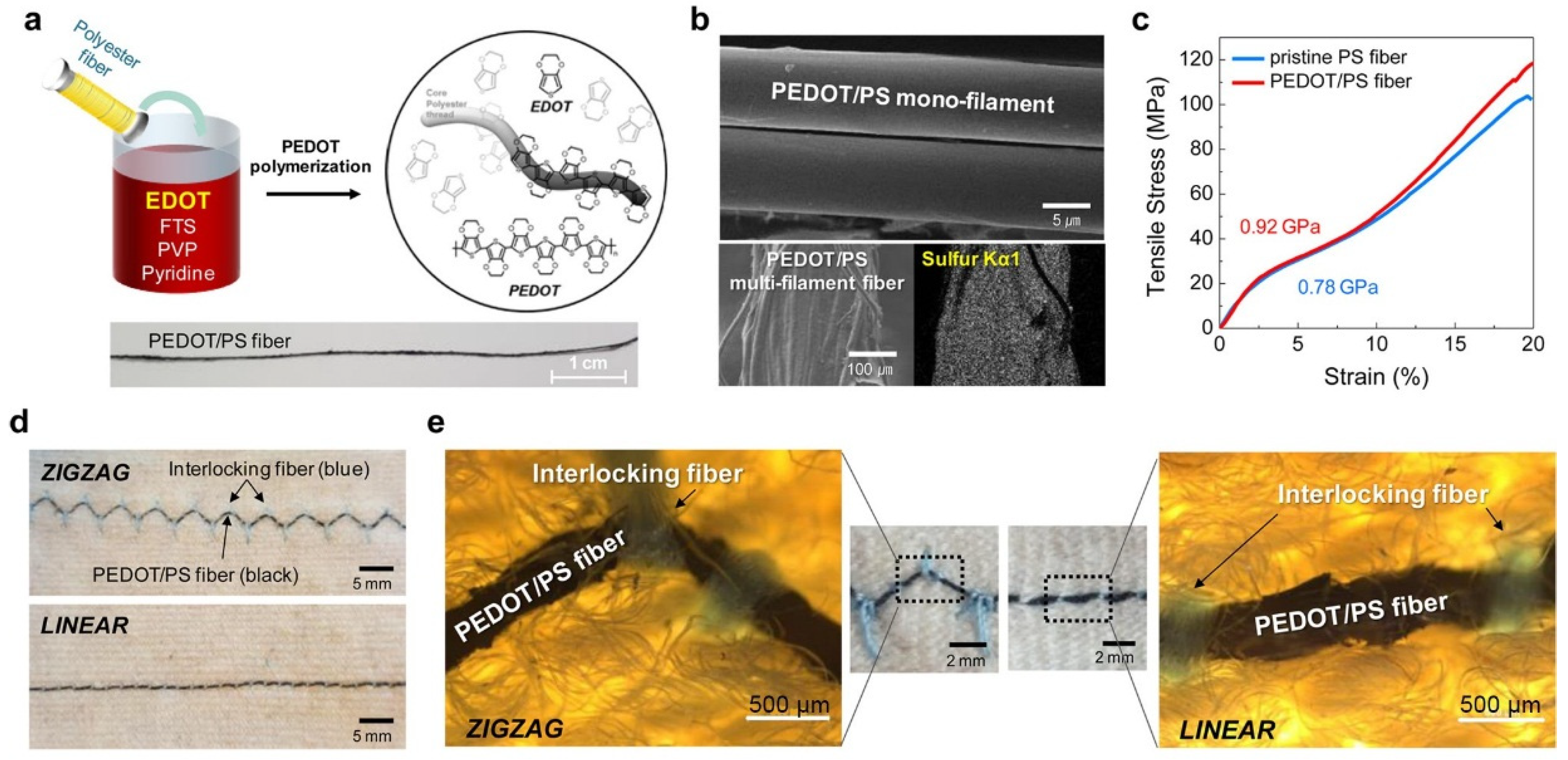
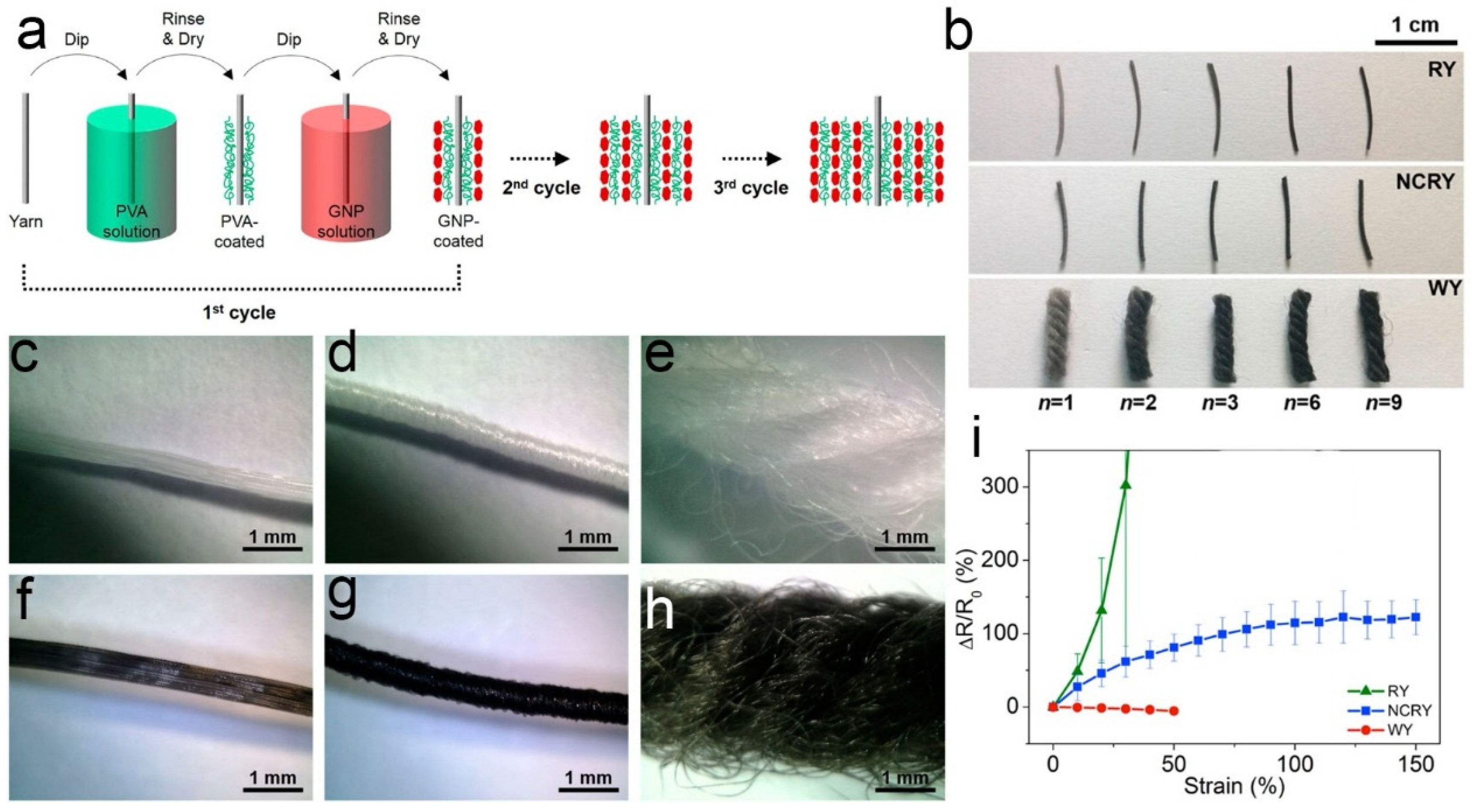
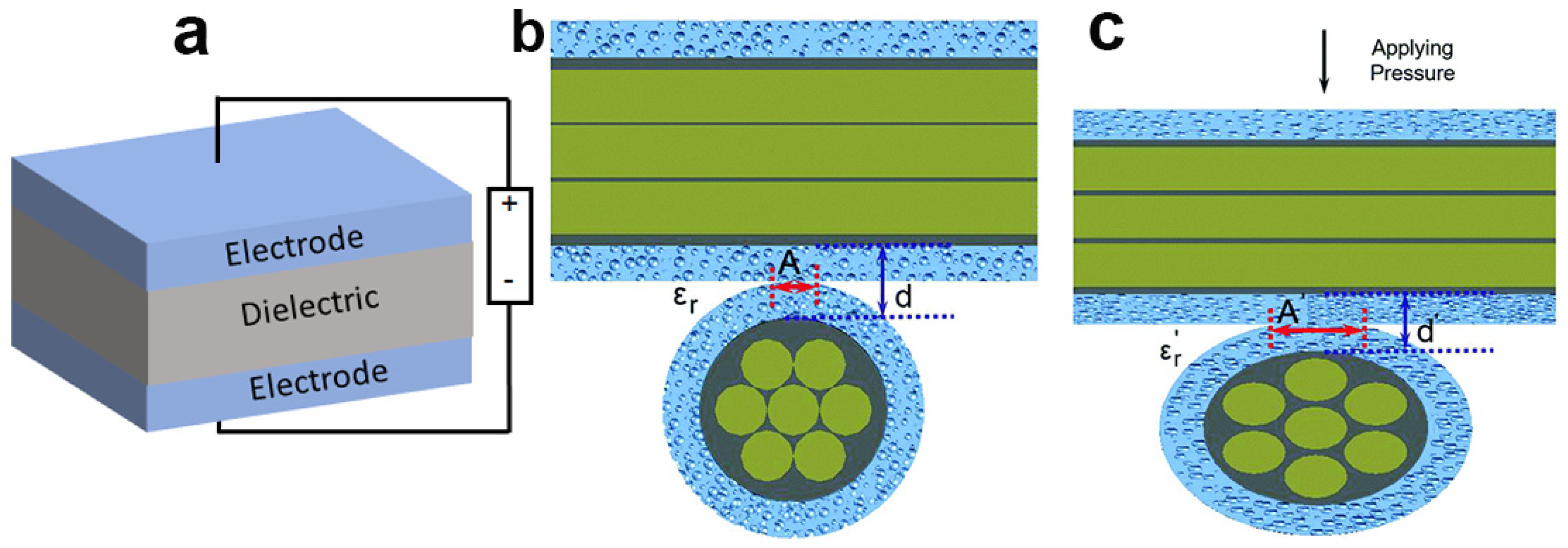
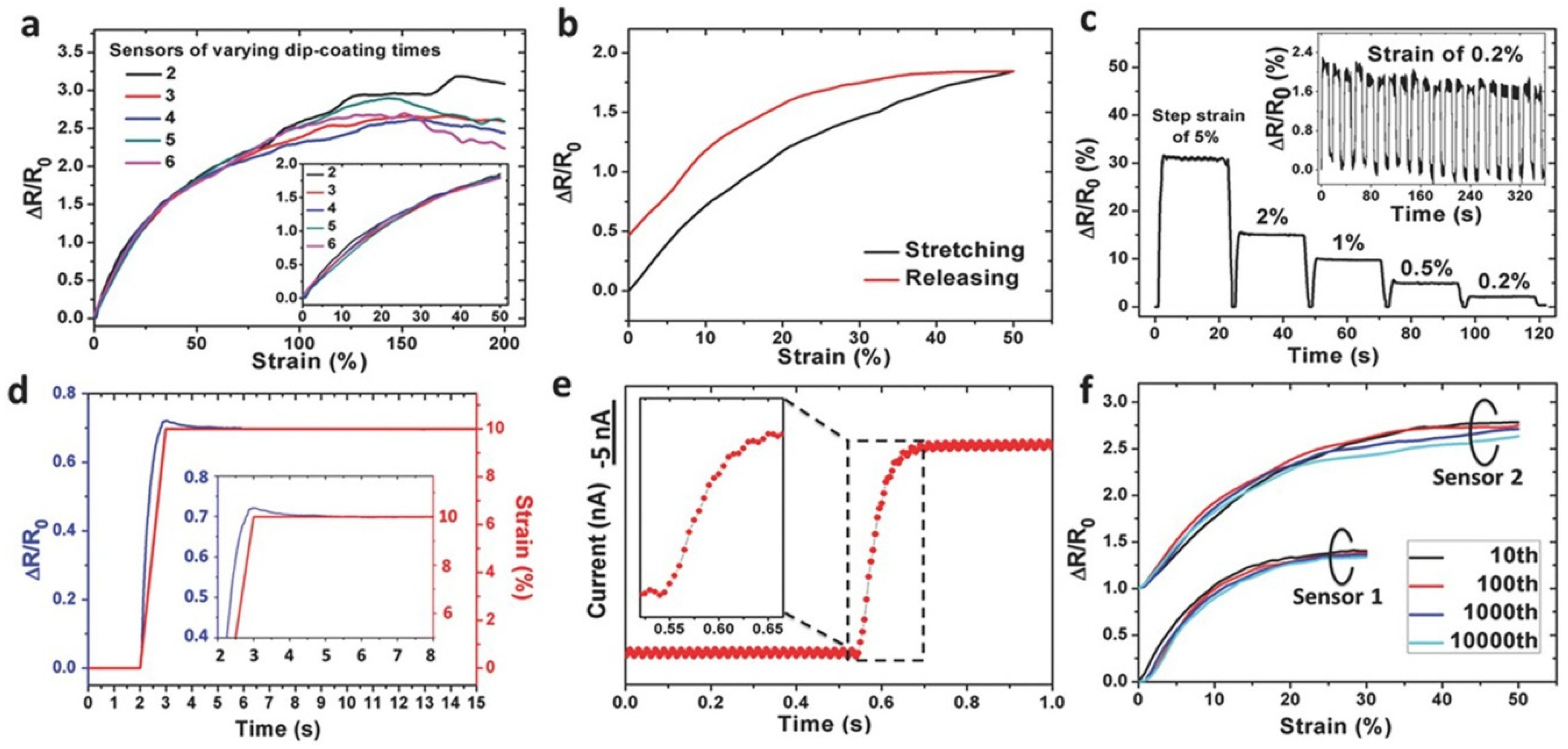
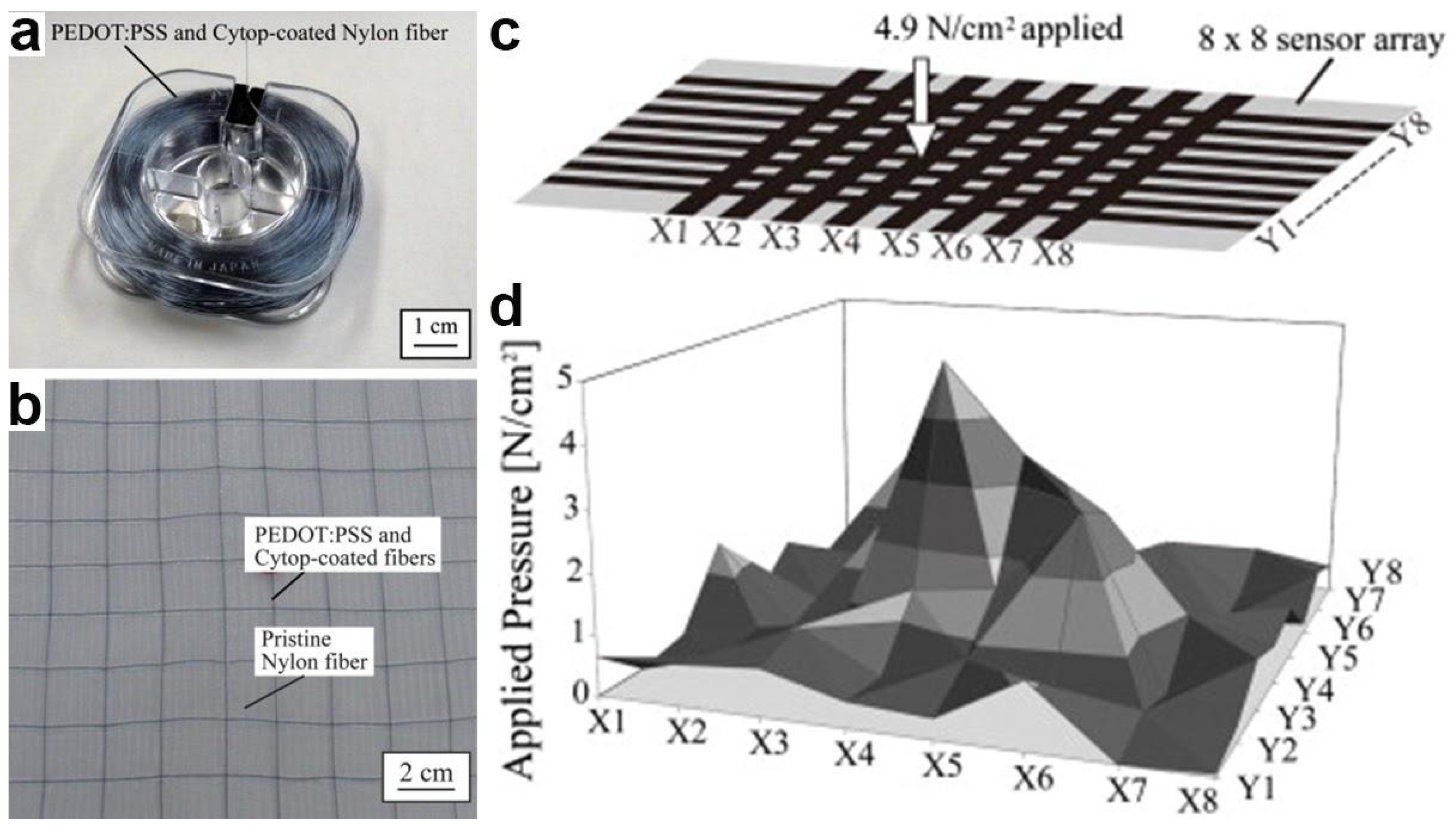
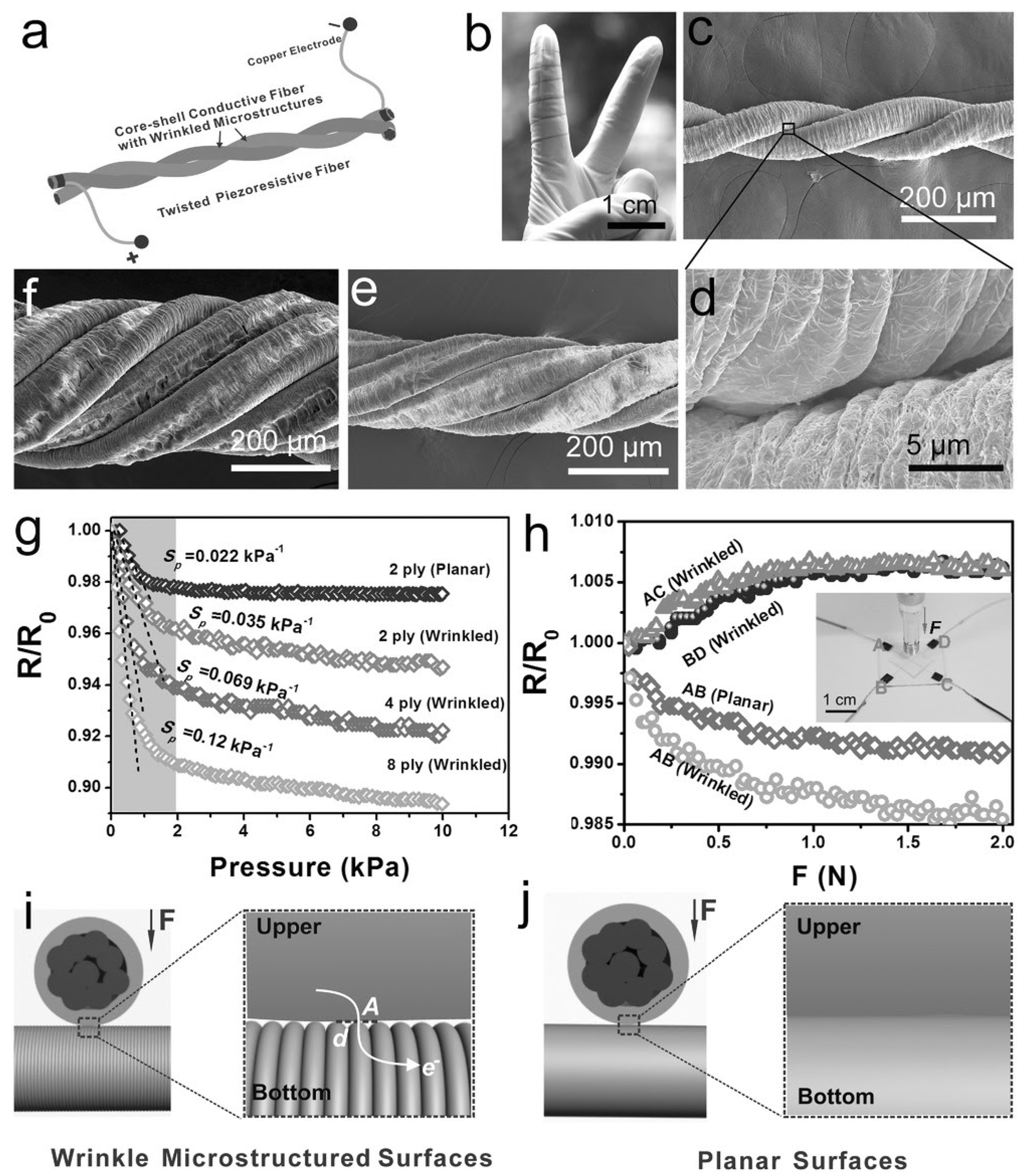
Table 1.
Fiber-based strain sensors coated with intrinsically conducting polymers.
| Materials | Fabrication | Sensing Mechanism | Sensor Properties | Applications |
|---|---|---|---|---|
| PET yarns and PEDOT encapsulated in PMMA [52] | In-situ polymerization | Interconnectivity between the PET/PEDOT monofilaments enhanced on straining, decreasing resistance |
| Human motion monitoring |
| PU yarn and PANI [130] | In-situ chemical oxidative polymerization | Region 1: conductive pathways broken. Region 2: increased contact between PANI chains, reduced rate of resistance increase. Region 3: PANI conductive pathways broken, resistance increased |
| Smart clothing |
| PU yarn and PEDOT:PSS, CNTs [132] | Dip-coating | When strained, the number of electrical connections between PEDOT:PSS fragments and CNTs agglomerates decreased, resistance increased |
| Human motion detection of subtle and large deformations |
GF: gauge factor, PSS: poly(4-styrenesulfonic acid), PU: polyurethane.
Table 2.
Fiber-based strain sensors coated with carbon nanotubes.
| Materials | Fabrication | Sensing Mechanism | Sensor Properties | Applications |
|---|---|---|---|---|
| Glass fibers and MWNT [155] | EPD | Region 1: dimensional changes in MWNT network. |
| In-situ tracking of microcracks to predict failure |
| Region 2: distance between nanoparticles increases | ||||
| Region 3: microcracks in MWNT network, resistance increases. | ||||
| Cotton yarns and SWNT [133] | Dip coating | Negative piezoresistance due to mechanical contact between SWNT coated fibers. Increased contact, improved electrical pathways, decrease in resistance. |
|
|
| Cotton threads and SWNT [117] | Dip coating | When strained, fiber-to-fiber contact changes, distance between nanoparticles increases, resistance changes. |
|
|
| PU core /cotton wrapper yarns and SWNTs [153] | Bobbin winding | When strained, disruptions in the CNT network formed, resistance increased. |
| Human motion monitoring (fingers, elbows, eye winks) |
| Cellulose yarns and SWNTs [134] | Bobbin winding | When stretched, gaps between yarns became smaller, conductive paths were improved, resistance decreased. |
| Integrated sensor/supercapacitor system for artificial intelligence and healthcare |
| PU threads and carbon ink/CNT [48] | Plasma treated | When strained, disruptions in the CNT network formed, resistance increased. |
| Integrated with microfluidics, temperature and pH sensors as TDD |
EPD: electrophoretic deposition, TDD: threat based diagnostic device.
Table 3.
Fiber-based strain sensors coated with graphene.
| Materials | Fabrication | Sensing Mechanism | Sensor Properties | Applications |
|---|---|---|---|---|
| Glass fibers, CNTs or graphene [154] | EPD | When strained, broken conductive pathways resulted in increased resistance. Disconnection of graphene was more severe, created larger resistance change compared to CNT coated fibers. |
| Embedded composite epoxy to detect damage in structural composites |
| PU core/PET wrapper fiber yarns and graphene oxide (GO) [116] | Dip-coating | When strained, GO/PET winding fibers separated, contact area decreased, resistance increased. |
|
|
| Rubber, nylon, wool yarns and GNPs [82] | Dip-coating | GNP coating on RY & NCRY cracks when strained resulting in broken electrical pathways, and increased resistance. When WY is strained there is greater contact between coated fibers, increasing conductivity. |
| Human monitoring–small and large motions |
| Spandex, PP silk, human hair and graphite flakes [85] | Meyer rod. | When strained, overlap area between graphite flakes decreased, resistance increased. |
|
|
Table 4.
Fiber-based strain sensors coated with other carbonaceous materials.
| Materials | Fabrication | Sensing Mechanism | Sensor Properties | Applications |
|---|---|---|---|---|
| PU core/nylon wrapper fiber yarns coated in silver nanowires (AgNWs), PDMS/CB rubber [126] | Dip-coating | When strained, the piezoresistive rubber layer changed thickness, resistance increased. |
|
|
| PU yarns and polymer/CB composite [156] | Dip-coating/EPD | When strained, CB/composite layer formed cracks, resistance increased. |
|
|
PDMS: polydimethylsiloxane.
Table 5.
Fiber-based strain sensors coated with metals.
| Materials | Fabrication | Sensing Mechanism | Sensor Properties | Applications |
|---|---|---|---|---|
| PU yarn and AgNW ink [114] | Chinese brush pen | Region 1: resistance was well sustained before the wrinkled microstructures flattened. |
|
|
| Region 2: AgNWsslippage deformed the conductive networks and increased resistance. | ||||
| Region 3: excessive AgNWs slippage ruptured conductive networks and increased resistance. | ||||
| Rubber core/PU wrapper yarns, P(VDF-TrFE) nanofiber mat, AgNWs [115] | Dip-coating | Region 1: resistance increased monotonically and slowly, wrinkled microstructures became gradually flattened. |
|
|
| Region 2: slippage of AgNWs deformted the conductive networks, resistance gradually increased. | ||||
| PU core/PET wrapper fiber yarns and AgNWs [118] | Dip-coating | When strained, AgNW layer cracked, resistance increased. |
|
|
Table 6.
Fiber-based pressure sensors coated with intrinsically conducting polymers and carbonaceous materials.
Table 6.
Fiber-based pressure sensors coated with intrinsically conducting polymers and carbonaceous materials.
| Materials | Fabrication | Sensing Mechanism | Sensor Properties | Applications |
|---|---|---|---|---|
| Nylon fiber, PEDOT:PSS Cytop (dielectric) [136] | Nozzle/die-coating | Fibers woven into array. When pressure applied, overlapping electrode area was increased, thus causing a change in capacitance. |
|
|
| Cotton threads coated and SWNT [117] | Dip-coating | When loaded, fiber-to-fiber contact changes, distance between nanoparticles increases, resistance changes. |
|
|
| PU core/nylon wrapper fiber yarns coated in AgNWs, PDMS/CB rubber [126] | Dip-coating | When strained, the piezoresistive rubber layer changed thickness, resistance increased. |
|
|
Table 7.
Fiber-based pressure sensors coated with metals.
| Materials | Fabrication | Sensing Mechanism | Sensor Properties | Applications |
|---|---|---|---|---|
| Hollow rubber fiber, gold (electrodes) [127] | Sputtering | When load applied to fiber crossover point, contact area between the warp and weft fibers increased, resulting in change in capacitance. |
| Tactile sensors in bedding, clothes, chairs, and shoes |
| Cotton fibers, Pt (electrodes) PDMS (dielectric) [26] | Low temp ALD | When load applied to fiber crossover point, contact area between the fibers increased. Additionally, dielectric thickness decreased, resulting in change in capacitance. |
| Textile electronics |
| PU yarn and AgNW ink [114] | Chinese brush pen | Two fibers twisted together for pressure sensing. When pressure applied, contact area between twisted fibers increased, resistance decreased. |
|
|
| PU core/PET wrapper fiber yarns and AgNWs, silicone (dielectric) [118] | Dip-coating | When load applied to fiber crossover point, dielectric thickness decreased, resulting in change in capacitance. |
| E-skins |
| Kevlar fibers, SBS, AgNPs (electrodes), PDMS (dielectric) [24] | Coating | When load applied to fiber crossover point, contact area between the fibers increased. Additionally, dielectric thickness decreased, increasing capacitance. |
| Human-machine interface |
| Twaron fibers, SBS, AgNPs, PDMS (dielectric) [119] | Dip-coating | When fiber crossover point is loaded, contact area between the fibers increased. Additionally, dielectric permittivity changes due to pores within the dielectric collapsing, resulting in change in capacitance. |
|
|
ALD: atomic layer deposition, SBS: poly(styrene-block-butadiene-styrene), AgNPs: silver nanoparticles.
© 2019 by the authors. Licensee MDPI, Basel, Switzerland. This article is an open access article distributed under the terms and conditions of the Creative Commons Attribution (CC BY) license (http://creativecommons.org/licenses/by/4.0/).
Share and Cite
MDPI and ACS Style
Chatterjee, K.; Tabor, J.; Ghosh, T.K. Electrically Conductive Coatings for Fiber-Based E-Textiles. Fibers 2019, 7, 51. https://doi.org/10.3390/fib7060051
AMA Style
Chatterjee K, Tabor J, Ghosh TK. Electrically Conductive Coatings for Fiber-Based E-Textiles. Fibers. 2019; 7(6):51. https://doi.org/10.3390/fib7060051
Chicago/Turabian StyleChatterjee, Kony, Jordan Tabor, and Tushar K. Ghosh. 2019. "Electrically Conductive Coatings for Fiber-Based E-Textiles" Fibers 7, no. 6: 51. https://doi.org/10.3390/fib7060051
Note that from the first issue of 2016, this journal uses article numbers instead of page numbers. See further details here.