Using the ARCADIA/Capella Systems Engineering Method and Tool to Design Manufacturing Systems—Case Study and Industrial Feedback

1
LAAS-CNRS, Université de Toulouse, CNRS, INSA Toulouse, 7 Avenue du Colonel Roche, 31400 Toulouse, France
2
College of Economics and Management, Beijing University of Technology, Beijing 100124, China
*
Author to whom correspondence should be addressed.
Systems 2023, 11(8), 429; https://doi.org/10.3390/systems11080429
Submission received: 8 May 2023
/
Revised: 25 July 2023
/
Accepted: 31 July 2023
/
Published: 16 August 2023
Abstract
:In a trend towards digital continuity, model-based systems engineering is becoming widely adopted for the design of complex systems, supporting system development from the very first stages. A narrow panel of methods and tools are available on the market; they offer different scopes and approaches, are more or less intuitive to follow, and are sometimes supported by tools. Among them, the Architecture Analysis & Design Integrated Approach (ARCADIA) is becoming popular and is gradually spreading in different industrial fields to model a wide variety of systems at different stages of their development and from different points of view. It is implemented using an open-source tool called Capella. Few feedback on its use in industrial settings have been published, while other feedback remains confidential. The goal of this paper is to analyze the interests and limitations of ARCADIA/Capella. To reach this goal, we experimented with ARCADIA/Capella in several projects and chose one to explain how the method and tool proceeded. In addition, we conducted a survey to obtain industrial feedback. As a result, the paper gives an overview of the relevance of ARCADIA/Capella in projects and of its usefulness, effectiveness, and adaptability in modeling different types of systems. It also provides some perspectives for the evolution of the method and the tool according to industrial feedback.
1. Introduction
Systems engineering activities govern every technical and human aspect of the development of a system throughout its whole life cycle [1]. Nevertheless, the complexity of systems is ever-increasing due to their multidisciplinary nature, growing customer requirements, and multiple external constraints [2]. Managing this complexity has become crucial in the success of projects, despite a rigorous application of systems engineering processes. To address this issue, systems engineering has slowly moved towards model-based systems engineering (MBSE), which provides engineers with methods and tools to model complex systems and follow their evolution during their whole life cycle (from concept design to operations) [3].
With the increasing attention given to MBSE, many methods and tools have been developed. Among them, ARCADIA provides a methodology to progress towards the complete modeling (functions, architecture, constraints, etc.) of a system [4,5]. It is supported by the Capella software tool [4,6,7]. At present, there is little literature on this method and tool, which is nevertheless attracting a growing interest from systems engineering practitioners. ARCADIA/Capella is mainly presented with a pragmatic objective and promoted in books [4,8] and through online webinars. Alai compares it with other methodologies such as the object-oriented SE method (OOSEM) or IBM Harmony [9]. In addition, some industrial case studies are presented on the Eclipse website [10]. However, as ARCADIA/Capella has only recently spread in the industry, less research has put into perspective the advantages and limitations of the tool in different situations.
To address this point, the goal of this paper is to support the researcher and practitioner via a tool-supported method by exploring the possibilities offered by the ARCADIA method and the Capella tool, e.g., for retro-engineering or redesign with less effort, while maintaining the coherence of functional and architectural models, as well as demonstrating how it addresses practicing industrialists’ needs. To this goal, we carried out several case studies to learn from by using ARCADIA/Capella in different representative situations and conducting a survey of industrial practitioners. Our motivation here is to provide our experimental results in as much detail as possible and to explain them step by step in a pedagogical way so that the experiments can be reproduced.
Section 2 first provides a preliminary overview and positioning of systems engineering methods and tools. Section 3 focuses on the ARCADIA method. The Capella tool supporting the method is presented in Section 4. Section 5 shows how to use ARCADIA and illustrates the Capella application in a simple industrial case study. It shows how to apply ARCADIA/Capella in different situations and highlights their interests and limitations. Based on a conducted survey, the feedback of industrial practitioners, completed with an overview of some advanced features of the tool, is provided in Section 6. Section 7 draws the conclusions and gives the perspectives.
2. Model-Based Systems Engineering
In accordance with the vision of the International Council of Systems Engineering (INCOSE) [2] about the future challenges that systems engineering will face in the next decade, considering human and societal needs as well as global and technology trends, this section highlights the interests of MBSE and provides an overview of MBSE methods and tools. According to [11], systems engineering is a transdisciplinary and integrative approach to enable the successful realization, use, and retirement of engineered systems, using systems principles and concepts, and scientific, technological, and management methods. Systems engineering (SE) provides a systematic approach, a framework and language accessible to anyone, to create holistic solutions that allows crossing the boundaries of other disciplines [12,13,14]. It is defined by the INCOSE and IEEE Systems Council as an “interdisciplinary approach governing the total technical and managerial effort required to transform a set of stakeholder needs, expectations, and constraints into a solution and to support that solution throughout its life” [15].
As highlighted by this definition, systems engineering is concerned with understanding the needs of stakeholders and the context of the problem and determining how to meet those needs with a system or product throughout its useful life. It focuses on eliciting, analyzing, and documenting customer needs and the required functionality and then transforms these needs and requirements into an optimal and validated solution using architecture and design analyses [16]. SE can be viewed as a methodology, a set of methods and tools, and a process [17].
According to the INCOSE analysis [2], future systems will need to respond to an expanding and diverse spectrum of societal needs to create value. System life cycles will need to be aligned with global trends in the industry, economy, and society, which will, in turn, influence system needs and expectations. In addition, systems will be more complex due to safety, environmental, security, performance, or human factor constraints: future systems will need to harness the ever-growing body of technology innovations while protecting against unintended consequences [18]. As a result, with this increasing system complexity, traditional document-based systems engineering (DBSE) is being progressively replaced by model-centric engineering to explore the use of models, which are more expressive and less ambiguous than documents, as presented in [1]. The adoption of MBSE enables an efficient systems engineering approach, which overcomes many challenges facing engineers [19].
MBSE is defined by the INCOSE as “the formalized application of modeling to support system requirements, design, analysis, verification and validation activities beginning in the conceptual design phase and continuing throughout development and later life cycle phases” [20]. It takes a holistic system approach to manage the system information and data relationships, treating all information as a model and therefore adding value to technical processes and project processes. MBSE is a move from a document-centric approach to a model-centric approach. All or part of the textual documents are replaced by models. In MBSE, a model represents a system and its environment. Models are usually created from meta-models (or conceptual models), which are sets of concepts within a system and the relationships among those concepts [15]. Different diagrams allow representing different points of view of the same model.
The MBSE approach supports systems engineering and the complexity resulting from interdisciplinarity. MBSE not only ensures that the language/tool/approach chosen will allow the system to be ‘represented’, but also ensures that the information can be properly used to support systems engineering. MBSE provides a representation of information in different ways that show specific analysis capabilities for different types of users that have different interests. It also allows refining a system and a system model into subsystem models.
According to several analyses and feedback [15], MBSE brings many benefits to SE practices in different fields, including technical and management processes. It allows better control of the system complexity thanks to a formalized, unambiguous, and complete modeling of the functional requirements. The manipulation of models offers a practical way to perform trade-offs and comparisons between alternative designs. MBSE allows traceability between the different views and between models of different levels of abstraction to be easily established; in this way, it also improves the quality, consistency, and completeness of the system definition. Moreover, verification, validation, safety, and system performance analysis activities are enabled during design definition using model checkers or simulation tools [21]. Finally, according to [9], MBSE also helps in reducing development costs and improving productivity (thanks to the possibility of reusing and simplifying design models and promoting communication between people working on the project).
A model can be captured via a mathematical equation, a graph, a formal expression, or a drawing. MBSE ensures consistency across all views by using one model at its core from which all the views are derived. Views can express different points of view, for example, the structure of a system, its behavior, and its interaction with its operational context [15]. These views can be represented with different modeling languages and tools following various methodologies, according to the domains involved in the system, the level of detail, the system aspects to be modeled, etc. The model-driven approach is organized around languages (SysML, DSL, UML, etc.), methods (OOSEM, ARCADIA, SPES, etc.), and tools (CAPELLA, CORE, Cameo Systems Modeler, Cameo Enterprise Architecture, Papyrus, etc.).
The methods offer a framework that helps to model a system by providing guidelines. For example, in [22], OOSEM is a top-down method with object-oriented concepts using systems engineering methods to create the right architecture for a multidisciplinary system. The Business Process Modeling Notation (BPMN) specification was developed by the Business Process Management Initiative (BPMI), and it defines the Business Process Diagram (BPD), which is based on a flowchart technique tailored for creating graphical models of business process operations [23,24].
Table 1 compares some of the most commonly used methods in systems engineering, most of which are presented in [22]; more details can be found in [9,22]. Each method is supported by a dedicated tool, a formalism (or language), and processes (a set of actions that can be performed). Each method offers different advantages.
Most of the methods presented in the table above are based on SysML or the languages inspired/derived from it. SysML stands for “systems modeling language” and is a general-purpose modeling language designed to support systems engineers in specifying, designing, analyzing, and verifying systems [30]. This language is derived from the Unified Modeling Language (UML), a standard for model-based software development, and it is used in all phases of development as described in [31]. Providing a standard view of modeling, UML uses the concepts of class and object to optimize code generation [32]. SysML uses the same concepts but replaces class modeling with block modeling, defining a vocabulary that is more adapted to systems engineering [9]. SysML models are based on nine types of diagrams, modeling either the system behavior (e.g., activity or sequence diagrams) and structure (e.g., block definition diagram), or the requirements (e.g., requirement diagram).
However, some studies consider that SysML remains too complex or not completely adequate for systems engineers. Indeed, as described in [33] and underlined by the AFIS Working Group «MBSE avec SysML» [34], a limitation of the SysML language lies in the lack of the notion of function. In SysML, however fundamental in system development, the concept of function is not clear because it corresponds to both activities (actions and blocks). SysML also does not allow dissociating the structural elements from its functions. Belloir, Bruel, and Faudou argue that it is difficult to use SysML with respect to the requirements described in other languages/tools such as Word or Simulink [35]. Moreover, the management of elements at the instance level is another current weakness outlined by [36]. It is impossible to distinguish each candidate architecture by associating different characteristics to perform nonfunctional analyses (safety, performance, etc.). In addition, as SysML does not impose any method or modeling guidelines, as explained by [9], and allows the practitioner great freedom in the creation and use of the diagrams, this may induce some form of ambiguity in its utilization. These are the reasons why some companies or consortiums feel that SysML is not completely adequate to model systems.
3. The ARCADIA Method
3.1. ARCADIA/Capella Genesis
The Architecture Analysis and Design Integrated Approach (ARCADIA) is an MBSE method developed by the Thales group in 2000, when it evolved from a simple supplier of equipment to a supplier of integrated systems [4]. In 2001, the group carried out a study of the current MBSE standards, methods, and tools, which concluded that the methods covered too limited a part of Thales’ activities and were too far from the company’s practices. Moreover, the use of UML as a modeling language, in addition to being somewhat complex for use, did not seem to be appropriate for system design. At the same time, a survey was conducted within the company to gather feedback and ideas for improving practices. Despite the diversity of answers, several major general pathways for improvement emerged [33]:
- Understand the customer/user needs;
- Define and share the solution among stakeholders;
- Secure system/software/hardware engineering and prepare subcontracting;
- Evaluate and justify architectural design early;
- Prepare and master verification and validation.
Therefore, in 2006, a first version of the ARCADIA method was released with structured recommendations of a top-down approach where the activities were clearly defined and followed one another in a fixed order [4], in conformance with the ISO/IEC 15288 standard [37]. Between 2008 and 2010, a tool called Melody Advance was internally deployed throughout the Thales group. Its open-source version, Capella, appeared in 2015. In complete accordance with the ARCADIA method, it provides tools to model systems, hardware, or software architectures using various diagrams. Its structure supports the application of the ARCADIA method’s architecture levels and concepts to use a unified language through the process and ensure co-engineering. The software tool is in continuous improvement, a major update is released each year to add new functionalities, and some minor versions are delivered to fix bugs. The new functionalities can meet needs associated with particular fields of systems engineering, such as performance, safety, cost, or mass analyses. New functionalities as transitions from the system to the subsystem level can be added. Consequently, particular architectures can be modeled using extensions.
3.2. ARCADIA/Capella Walkthrough
ARCADIA is divided into four main levels and can be adapted to top-down, bottom-up, and iterative approaches [38]. Each step has its own objectives and advances progressively deeper into the design of the system [4]: Operational Analysis (what system users need to accomplish; for more details, see Section 5.1.1); System Need Analysis (what the system must achieve for actors; see Section 5.1.2); Logical Architecture (how the system will work to meet expectations; see Section 5.1.3); and Physical Architecture (how the system will be built; see Section 5.1.4). Figure 1 presents the global system V cycle and the local V cycle of the system architecture stage.
As shown on the left of Figure 1, the ARCADIA method decomposes the system architecture stage of the V cycle into four steps (corresponding to the Capella 4 levels): operational analysis, system need analysis, logical architecture, and physical architecture.
ARCADIA is implemented in a dedicated tool, Capella.
4. The Capella Tool
The main interest of Capella is that it maintains consistency and coherency between the modeling levels: the constituent elements of each level are linked to each other via traceability links and justification (an example is presented in Section 5.1.3).
As presented in [4], the purpose of Capella is to support system architecture, a key stage in system development. According to the ARCADIA method, Capella starts from the elicitation of the stakeholders’ needs, and it guides the design process until the exploration of the different technological and architectural possibilities of the solution domain is realized. Through the method at different levels, it allows a graphical, organized, and simplified understanding of the design stage.
Capella proposes a metamodel that can be used in different ways. Among them, the most common consists of following the classical top-down ARCADIA process (see the case study in Section 5.1) from the operational analysis to the physical architecture when designing a new system. Capella also allows performing a bottom-up method for retro-engineering (see the case study in Section 5.2) when the system development is based on an already existing system or on its parts. Finally, the tool can be used to solve a specific problem by analyzing only one level (for example, an interface problem can be analyzed at the logical architecture level).
Being very guided by the ARCADIA method, the Capella tool allows the creation of different elements (diagrams, activities, interactions, actors, capacities) that are adapted to each step of the method. As shown in Figure 2, some tools are provided by Capella to facilitate the handling of the software tool. The Activity Explorer displays the different levels of architecture, with shortcuts to create associated diagrams within those levels and facilitate the transitions between levels. The Semantic Browser allows navigating throughout the model. When an element is selected, it displays all the involved relationships and references existing within the model. The Project Explorer represents the tree of the Capella project, listing all the diagrams and elements created by the user. Properties displays all the properties of a selected element of the model. Information provides a quick debugging solution for model validation, indicates the type of error and the associated rule that is lacking in compliance, and allows checking the selection for error messages or warnings.
The following subsection illustrates the application of the four levels of ARCADIA/Capella on a simple system.
5. Experimenting ARCADIA/Capella
To illustrate the application of ARCADIA/Capella, we consider the design of a counter bell, adapted in [40], which is used in hotels to notify the receptionist of the presence of a client. The system should be accessible to everyone and be operational during opening hours. There are no technological constraints.
5.1. Top-Down Analysis of the Counter Bell
Hereafter, we apply the methodology step by step and illustrate how we move from one level to another.
5.1.1. Operational Analysis
First, it is necessary to start with a need analysis, corresponding in Capella to the “Operational Analysis (OA)”. This step allows for capturing the stakeholders’ needs, independent of any solution. This means identifying all the operational entities (Capella’s name for stakeholders) involved in the different stages of the life cycle and their interactions with the project. Each entity, whether physical or not, will express her/his/its needs that are transcribed as an operational activity or a constraint. One of the particularities of the operational analysis is that the system is not recognized as a modeling element. It is only at the next level that certain elements (entities and/or operational activities) will be assigned to the system.
Analyzing the example of the counter bell, three operational entities can be identified: the client; the receptionist, who are two operational actors (human operational entities); and a third operational entity, the hotel, hosting the two others. The association of the client and the receptionist with the operational entity is described in Figure 3, showing an operational entity breakdown (OEBD) diagram. This diagram is mainly used to list the operational entities and to show the relationships between them.
Figure 3 shows the operational actors contained in the hotel. This corresponds to what is described in the OEBD diagram in Figure 3. The client notifies the receptionist of his arrival at the counter by using an audible signal, and the receptionist comes to welcome the guest in response. ‘Notify the receptionist’ (the same for ‘Welcome the client’) is represented by an operational activity (orange rectangle) inside the box ‘Client’ in Figure 4. This corresponds to an allocation relation, meaning that the operational activity is allocated to the client entity. Moreover, between activities, an operational interaction named ‘Signal’ appears. It corresponds to an exchange of information between the operational activities. To complete the OAB diagram, it is possible to add communication means between the operational entities. Here, the client can notify the receptionist with the sound.
Once this step is completed, all the created elements are listed in the project explorer (as shown in Figure 5), where they are automatically sorted by Capella (unlike the Cameo Systems Modeler, for example). If the project were more complex, there would be more operational entities, more operational interactions, and more possible operational scenarios (a scenario describes the behavior of entities and/or operational activities in a specific context [8]). In this case, it would have been interesting to create specific capacities (a capacity is a modeling element that provides a high level of service to achieve an operational objective [8]) and scenarios for each situation that the system may encounter.
5.1.2. System Analysis
After defining all entities that will participate in the mission, the next phase, called system analysis (SA), aims at identifying functions (behaviors or services) that will satisfy the operational needs defined in the previous level [8]. The Capella tool allows automatic transitions between the different analysis layers. In this way, all operational entities with associated activities become actors with associated functions at this level.
In contrast to the OA, the SA introduces the notion of a system, which represents an organized group of elements that work as a unit (black box). The main idea of this phase is to understand what the boundaries of our system are; that is, which functions will finally be allocated to the system and which ones will continue to be allocated to the external elements, the actors. Therefore, at this level, the identification of the system is accomplished through its interactions with all actors. The exchanges of information or matter between the functions are allocated to the system (which becomes ‘system function’) or allocated to the actors that are named ‘functional exchanges’. Finally, Capella allows creating channels that circulate the exchanges between the system and the actors, which are called ‘component exchanges’.
In the counter bell example, all previously defined elements (in the OA level) can be represented in a system analysis blank (SAB) diagram (see Figure 6). In this way, the system (the doorbell) and the actors (the client and the receptionist) are represented as blue boxes. Moreover, we assumed at the operational analysis level that there is a sound signal between the client and the receptionist. In the system analysis, the sound signal will pass through the mechanical counter bell. We then add a series of functions to the SAB diagram that we allocate to the counter bell system. These functions are as follows (see Figure 6):
- Ring: transmits the system’s sound signal to the receptionist;
- Activating the ringer: receives the client’s ‘activation order’ to ring the counter bell and transmits it to the ring function;
- Stop the ringing after a while: receives the ‘ringing start time’ and transmits a stop signal ‘end of ringing’ after a certain amount of time.
Finally, to refine the model of the counter bell, it is also possible to clarify the interfaces between the system and the external actors by adding component exchanges, namely, ‘client UI’ and ‘sound wave’ (see Figure 6).
The SAB diagram is a static representation, and it does not consider the time constraints that could exist in the functional analysis. However, the ‘stop ringing’ function is triggered 30 s after the ‘ring’, which will constrain the choice of architecture in the next phase. To describe the temporal behavior of the system, scenario diagrams are available from this phase. As shown in Figure 7, the exchange scenario diagram illustrates not only the exchanges that take place between the different actors and the system, but also the types of activation (a duration of 30 s between two activities, for example).
Note: as this example does not present any major difficulty for its understanding, we will not describe any other diagrams in detail.
This level of analysis provides an accessible approach for inexperienced systems engineers. The notion of function is clearly established as presented in [36] and allows us to obtain a closer view of the theoretical processes of systems engineering. In addition, a number of semantic elements, such as functional chains, constraints, etc., allows for a better visibility of the diagrams. Capella allows us to present different views/aspects of the system according to the aimed stakeholder: indeed, the granularity and the type of information are different for the engineer and the client.
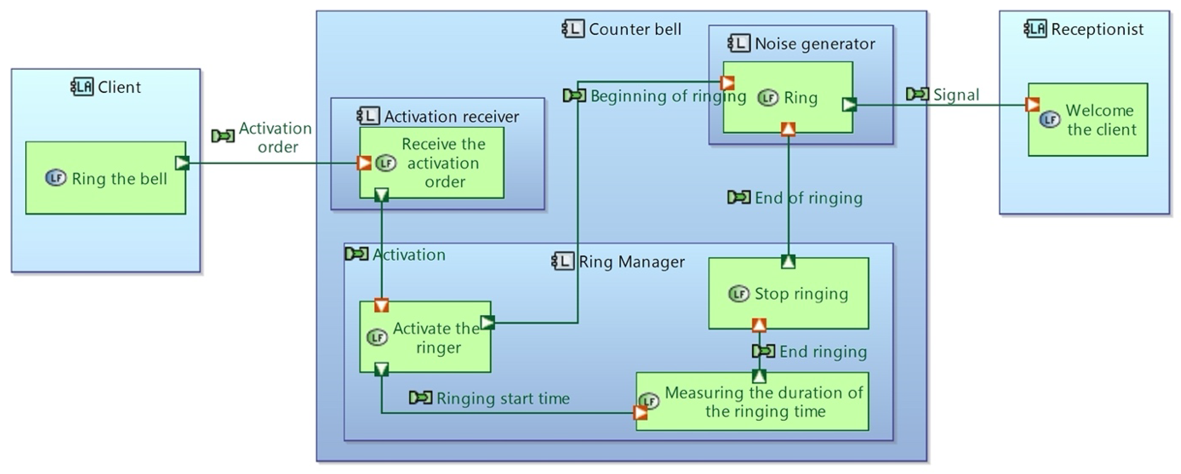
5.1.3. Logical Architecture
After the system analysis, a logical architecture must be made. The goal of this level is to remain independent of the final physical implementation and its technology. Therefore, the components presented in this phase can be suitable for several further solutions.
To present the architecture of the counter bell example, a LAB (logical architecture blank) diagram can be built, as shown in Figure 8. In this diagram, we recognize our system, the ‘counter bell’, which now contains logical components (structural elements of the system that can interact with other components or actors), such as the ‘activation receiver’. At this architecture level, we find the equivalent elements of the SA level. Thus, the functions become logical functions, and the actors become logical actors. For example, the logical actor ‘client’ can ‘ring the bell’.
As shown in Figure 8, certain functions have been added according to system analysis, such as ‘receive the activation order’. This was necessary because to be able to activate the ringer, the system had to be able to receive the activation order. However, these two actions require two different components, and, therefore, two different logical functions.
Additionally, although the logical architecture is the first step in the world of the solution, the names given to the components or functions are still generic. The objective of this step is to avoid orienting the technological choice of the solution and to allow everyone to propose their ideas based on the same logical architecture.
Moreover, with the progress of the project, it is possible to forget some of the allocations previously made or the links between some elements. Therefore, the Semantic Browser (see Figure 9) allows checking the traceability of information between levels.
If we take the example of the logical function ‘activate the ringer’, we can find that, thanks to the Semantic Browser, this function comes from the system level. Here, we notice that it realizes the system function ‘activate the ringer’ and that it is allocated to the logical component ‘ring manager’. We can also examine its inputs and outputs. As shown in Figure 9, the logical function ‘activate the ringer’ receives a functional exchange called ‘activation’ from the logical function ‘receive the activation order’ and sends two pieces of information called ‘beginning of ringing’ and ‘ringing start time’ to two other logical functions.
Another advantage of Capella diagrams lies in the offer of building matrices. They can be generated at each step. They allow us to display the different relationships between the elements of the model and facilitate verification. This way, at the logical layer, we can check that each logical function is associated with a unique component and that each component has at least one associated logical function. An example is shown in Figure 10.
The logical architecture is the entry point into the solution world, without considering a particular technological solution. We can start evaluating the system, performing the safety analysis, and preparing the verification and validation steps. Co-engineering and cross-functional fields of systems engineering must be used to develop the optimal solution.
5.1.4. Physical Architecture
The physical architecture allows someone to understand how the system is built and what it is composed of. Thus, we find the logical functions and components in the physical system. Depending on the choice made for the solution, it is possible to modify the names and assignments of certain components and functions.
For example, in this case study, the counter bell is a mechanical bell, so we could have the architecture shown in the Physical Architecture Blank (PAB) in Figure 11. The activation receiver would become the push button, the ringer manager would become the hammer, and the sound transmitter would become the dome. These elements are represented as the blue boxes in Figure 11. There may be changes in the function assignments depending on the nature of the components (by its nature, the dome will manage stopping the ringing).
As shown in Figure 11, we add a new element, the pedestal (the box included in the mechanical counter bell) because all other components are positioned on this element. Moreover, we can see in Figure 11 that there are two types of components: the physical component (PC) nodes (in yellow), representing the physical elements in the material sense of the term, and deployed PCs (in blue), which are behavioral physical components.
Based on this case study, this section presented how the ARCADIA method guides the top-down architectural design process of a system. By following the different steps and using the main diagrams of the application, we managed to represent the system accurately. Later, this representation can be used to develop the components of the solution and to define the test sequences.
However, in a situation where a physical system already exists but the solution needs to evolve, if we have the models of the system, especially the physical architecture model, then we can adopt a bottom-up approach. To illustrate this situation, Section 5.2 considers the example of the doorbell to show that ARCADIA/Capella can be used not only to perform an initial design of a technical system, but also to make an existing system design evolve by retro-engineering following a bottom-up approach.
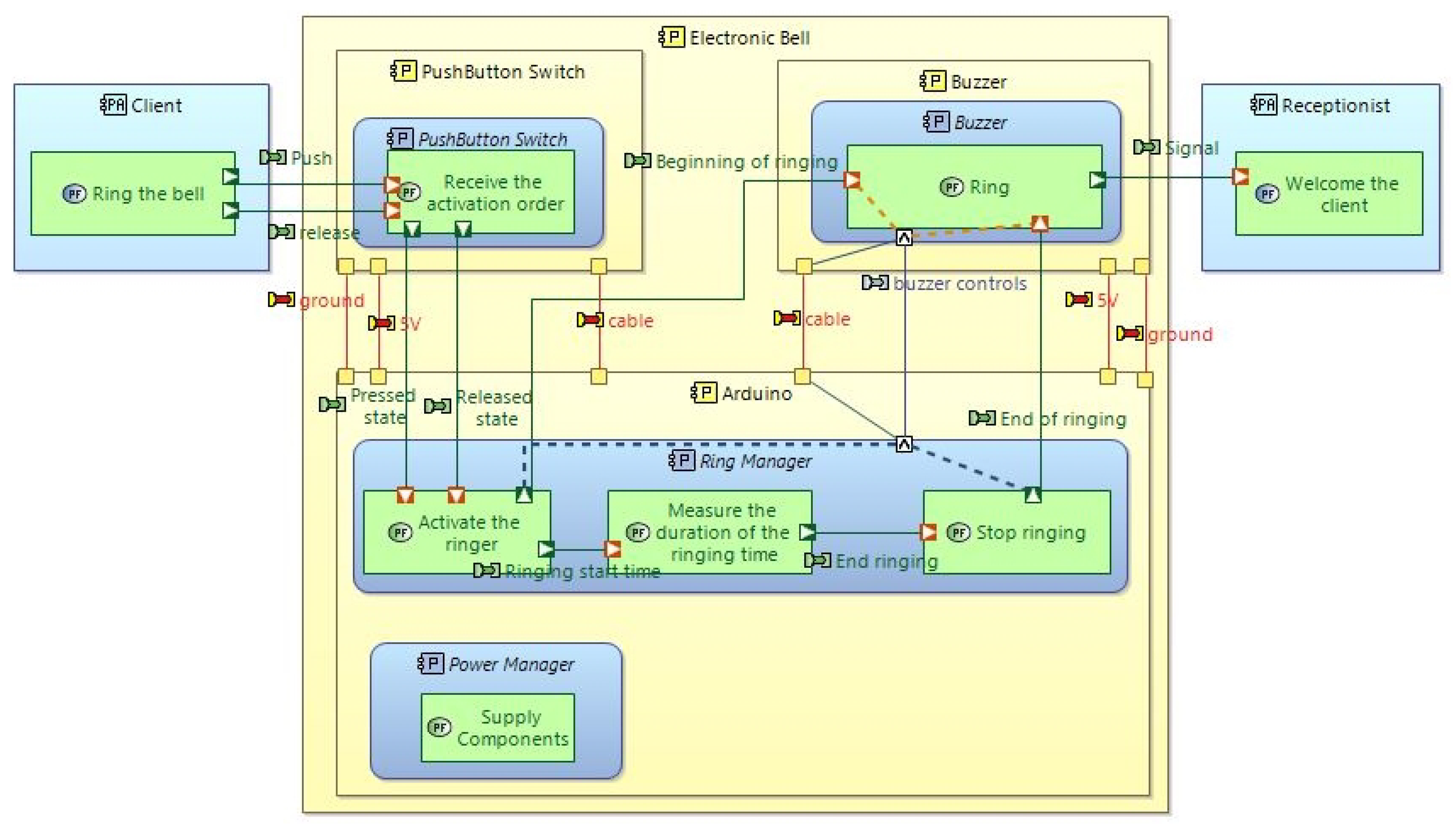
5.2. Retro-Engineering of the Counter Bell
Let us consider that the hotel owner (the customer who ordered the product) changes his mind and asks for the doorbell to be electronic. The stakeholders and their needs remain the same. Therefore, the physical layer is no longer adapted to the needs; however, we can reuse Capella’s logical layer to propose a new technological solution.
One solution could be to replace the dome and the hammer with a buzzer and an Arduino card, respectively, as shown in Figure 12. In this solution, a power manager has also been added. As several physical component nodes have been introduced, physical links between them are necessary to allow the exchanges between the functions via component exchanges (for example, the buzzer manager and the buzzer will exchange buzzer commands via a cable). They appear in red in Figure 12.
This example shows that we can easily obtain another implementation of the same expressed needs by re-engineering a physical solution from the reuse of its logical layer.
In this case study, we started with an existing physical model to recreate a new model. However, there are other bottom-up approaches in industrial projects. It is common to have a design team working directly on a prototype physical architecture (components, controllers, sensors) and a system team defining maturing system functions. Then, reconciliation between the system functions and the physical architecture must occur. These parallel activities cause a bottom-up approach when the project requires fast development.
6. Industrial Feedback on ARCADIA/Capella and Advanced Features
Even if this work primarily focuses on the support of the researcher and the practitioner using a tool-supported method and not on showing the features of the tool, this section, however, extends our conclusions with some feedback on the problems encountered by industrial practitioners of ARCADIA/Capella and on interests they found when using it to develop a project. To achieve this goal, we analyzed the online Capella forums and conducted a survey among a panel of industry practitioners. We therefore obtained some information on the practitioners, as well as on limitations and expressed needs related to the achievement of more complex projects.
Our survey was carried out over a three-month period between July and September 2020. More than 400 organizations worldwide using Capella have been identified by [41]. This number is growing exponentially, as shown in Figure 13.
Among them, we identified a panel of companies that consisted of users having different profiles in terms of geographical location, company size, and line of business. ARCADIA/Capella is indeed used in different fields of application, such as railways (Bombardier, SNCF [38]), aviation (Rolls-Royce [42]), aerospace (ArianeGroup [43]), automotive (Continental [44]), and energy (Framatome [45]). In this expanding ecosystem, organizations such as OBEO provide help and support to new users [10].
To proceed with this survey, we identified potential contacts either on LinkedIn, via internet searches, through participating in conferences, and from the online list of practitioners listed on the Clarity Ecosystem website. We ended up with a selection of thirty systems engineers. Among them, approximately fifteen engineers answered, with a variety of opinions. The collection of feedback was performed via a survey and interviews. A first set of generic questions aimed to give context of the company (size, activity sector, location, etc.). The main goal of the developed questions was to determine why the engineers interviewed were using Capella rather than other MBSE software and what, in their opinion, were the advantages and limitations. Depending on their use, we followed up with specific questions that included additional details, such as the use of add-ons, or the use of Capella following a bottom-up approach.
Figure 14 shows the distribution of identified Capella users according to the lines of business. It gives an idea of the impact of Capella in engineering: there is no specific sector in which this software is used; this domain independence can be an asset.
Figure 15 shows that the main contributors to the survey are French, and most of them are European, which can also represent a bias of the survey; however, we obtained a few answers from the USA and Brazil, therefore revealing the following.
In addition, as shown in Figure 16, this software is not used exclusively by companies of a specific size, though a plurality of Capella’s customers are large companies.
Through the survey feedback, we were able to gather several useful pieces of information and collect different points of view, which led us to several detailed insights about the benefits and limitations of using ARCADIA/Capella and some pathways to make the tool evolve, as presented below.
6.1. Highlighted Features
This section will present some features highlighted by the engineers interviewed. The topics that were most frequently mentioned will be discussed: flexibility, simplicity, traceability, visual tool, and open-source tool. Section 5.2 will illustrate some of these limitations that can be solved by the use of add-ons.
6.1.1. Flexibility
The first major benefit discussed is the flexibility of the software. Capella is a tool capable of adapting to companies and projects. It is not specific to a standard. For example, the tool can be used in automotive or aeronautics fields, indicating that it is possible to model systems from different fields of application. As shown in Figure 14, whether it is being used for nuclear, space, or telecommunications settings, Capella can model these systems.
This flexibility can also be found in the presence of projects that do not require an end-to-end systems analysis. Capella can be used at any level of a project: systems of systems, subsystems, low-level components, or software. It depends on whether the project requires an operational analysis, a functional analysis, logical architecture, and/or physical architecture.
It is equally possible to use only one level of modeling if we wish to represent only the physical or logical layer. Therefore, flexibility exists in the approaches, although the ARCADIA method, which accompanies Capella, allows top-down, bottom-up, or iterative approaches, if necessary, as presented in Section 3.2 [38].
However, some industries explain that Capella may not be flexible enough, especially since a predefined methodology is linked to the tool. The use of functional exchange in the logical architecture is too generic for some projects. For fast development, the use of different types of functional exchange (for example, DC or AC electrical power types) will permit faster development of models and allow for more efficient review with the design and software teams.
Another limit is the inability to allocate a system function to a physical component without passing through the logical layer. If the logical layer is considered useless, it is generally creating additional work.
6.1.2. Simplicity
The language and the software are understandable to beginners. While the abundance of diagrams and abbreviations takes some practice, engineers unfamiliar with the software code can more easily manipulate ARCADIA systems engineering concepts. For the less experienced practitioner, simple training is required, and most of the functionalities can be learned during on-the-job training. The user is guided in the usage of the tool by the method itself. Indeed, the method (ARCADIA) is known by the tool (Capella): the methodology is embedded, which is an advantage over other SysML tools (e.g., Cameo Systems Modeler), which are more open in their use but less simple. Moreover, the diagram types are similar between the layers, which makes them easier to learn: structural (SAB, LAB), dynamic (ES, functional chains), and interface diagrams, for instance.
Simplicity is also expressed in changes. Changing an element in one diagram affects the rest of the model. Moving the function from component A to component B will affect the entire layer. In addition, it is easy to reuse a model to evolve a solution. The presence of the logical layer makes it possible to reuse the same need analysis.
On the other hand, Capella has its own language and its own vocabulary, which is not entirely in accordance with ISO/IEC 15288. The simplicity allowed by this aspect can lead to confusion between two entities that do not use the same software or the same method. For example, the notion of a system of interest does not exist in Capella.
6.1.3. Traceability
As mentioned in Section 5.1.3, the Semantic Browser is an indispensable asset. When projects are vast, it is sometimes difficult to retrieve all the information about an element using a single diagram with a single view. The traceability provided by the Semantic Browser makes it possible to check the consistency of an element with the layer at which it is located and with previous layers. This “tool” simplifies and speeds up the search for accurate and complete information. However, the inability to save versions to be able to go back to in case of an error may be a problem when decisions need to be reversed; this shortfall prevents good traceability for the project in question.
6.1.4. Visual Tool
One of Capella’s most important advantages is visualization, which helps to communicate concepts. Thanks to the homogeneity of the colors, the readability and coherence of the diagrams between different levels are reinforced. For example, in the case study presented in Section 4, it can be seen that the operational analysis diagrams have orange, gray, and brown colors, whereas the logical architecture diagrams have green and blue colors.
Furthermore, a diagram represents one or more points of view of the system but must be easily readable and understandable. Filters simplify some parts to represent only a specific view of the model. For example, two functions may have several interactions in common, but it may be that only one of them is desired in a particular view. Another way of highlighting a view is the notion of functional chains. By helping to highlight a set of functions, it makes it easier to read a sequence on static diagrams.
However, some modeling problems require a significant amount of time to restructure the diagrams. The addition of elements and interactions can lead to the creation of real bags of nodes on the model. Alternatively, the inclusion of functional chains in Capella could be optimized for time savings because a manual adjustment of the diagrams is required.
6.1.5. Open-Source Tool
Two parts of this theme emerged from our discussions with the industry. The free-of-charge aspect promotes its diffusion among systems engineers. Indeed, the evolution of the ecosystem of users improves the tool with new add-ons and functionalities: The more actors there are, the more innovation there is. If the users associated with the project work on the same tool (suppliers, equipment manufacturers, designers, regulators, etc.), this makes it possible to develop the system in line with all the stakeholders.
Another way to take advantage of Capella is to modify the source code. As a result, it is possible to adapt the tool to a company, systems engineering team, or specific project. This would allow for a consistent workflow when using the tool.
However, the fact that Capella is open source can also be seen as a disadvantage. Indeed, adapting Capella to the projects of certain companies can be complex. ARCADIA/Capella alone is not enough; it must be used in interaction with other tools for good project realization, in accordance with ISO/IEC 15288. There are add-ons to add new features and support actions. However, not all of them are from the same development company, which can cause some problems. Typically, when Capella evolves and version changes occur, the add-ons owned by other companies do not necessarily follow the movement and are not always compatible with the current version of Capella. This is one of the disadvantages of open-source software. It is simpler to ensure the continuity of a project by acquiring a package of tools that allow the development of additional systems engineering activities (for example, the set of tools developed by IBM).
6.2. Evolution of ARCADIA/Capella
Our survey has highlighted several limitations, some of which can be solved in two ways: by developing extensions (specific add-ons) or by interconnecting Capella with other software. This section highlights two limitations raised by the survey:
- The first limitation (Section 5.1.1) concerns the inability of the basic tool to specify the different types of functional interactions.
- The second limitation raised in the survey (Section 5.1.3) is related to the lack of versioning and traceability of the models created with Capella.
To overcome the first limitation, the Thales group has developed an open-source extension called PVMT (Property Values Management Tools). This extension development is made possible thanks to the open-source aspect of Capella (Section 6.1.5), with a source code directly accessible to users, which allows the community of practitioners to adapt the tool to their needs. The PVMT add-on allows enriching the modeling of complex systems by defining and setting domain-specific properties on Capella model elements and changing the graphical aspect of elements according to their property values. As a result of the creation of domain property models, users can not only specify the graphical style of their domain properties, but also choose which ones may be displayed on the diagrams.
To overcome the second limitation, some industrial initiatives interconnect Capella with agile project management tools offering ticket management, to guarantee the traceability of model evolutions with version management tools. For example, Vitesco shared their experience of interconnecting Capella with Jira and Jenkins tools, resulting in a systems engineering framework with off-the-shelf, field-proven and mature solutions, which enables continuous integration and review. This approach can also be enriched with tools for requirements management, safety assessments, validation, and verification.
7. Conclusions
As model-based systems engineering enhances the ability to capture, analyze, share, and manage the information associated with the complete product life cycle, many organizations are moving from traditional document-based systems engineering to model-based systems engineering. Moreover, MBSE extends to domains beyond engineering to support complex predictive and affect-based modeling that includes the integration of engineering models with scientific and phenomenology models; social, economic, and political models; and human behavioral models [46]. We can see the development of several operational usages and the deep democratization of the MBSE for a wide variety of business areas and companies.
However, this journey remains challenging and has a huge impact on company practices and organizations. One of them is the deep gap between theory and practice; for example, the offer of model-based systems engineering methods and tools available on the market is still limited. To fill this gap, this paper focused on ARCADIA/Capella, an open-source method and tool whose use is becoming increasingly widespread in companies. Its aim is to support the systems engineering researcher and practitioner by exploring the possibilities offered by this method and its accompanying tool, as well as demonstrating how it meets the needs of practicing industrialists.
We first introduce and compare the different MBSE methods and tools to determine their advantages and weaknesses. Then, a detailed presentation of ARCADIA/Capella is provided to understand it comprehensively. Additionally, we illustrate the usage of Capella in an industrial case study from engineering and retro-engineering perspectives.
Moreover, five highlighted features of this software tool are identified by engineers through different case studies and an industrial survey. Generally, we can conclude that Capella is a powerful MBSE tool that is easy to learn and adaptable to many different types of projects. In contrast, due to the large number of domains in which the tool can be used, some weaknesses may appear because some projects or companies may have specific demands that are not adapted to the generic nature of Capella. These generally give rise to complementary developments to Capella, which are carried out in very close collaboration between the company that requests it and the developers of Capella. In this research, we identified the reactions of the sector, their appreciation of the interests and limitations of Arcadia/Capella, as well as the evolutions they felt were necessary to bring to the tool to meet their needs as closely as possible. From this analysis, it seems necessary to invest in the way of working on the integration of ARCADIA/Capella with other enterprise tools, particularly project management tools.
Author Contributions
Conceptualization, C.B.; methodology, C.B.; software, L.G. and V.O.; validation, C.B., L.G., V.O. and R.X.; formal analysis, C.B., L.G., V.O. and R.X.; writing—original draft preparation, C.B., L.G., V.O. and R.X.; writing—review and editing, C.B. and R.X. All authors have read and agreed to the published version of the manuscript.
Funding
This research received no external funding.
Data Availability Statement
Data available on request due to restrictions e.g., privacy or ethical.
Conflicts of Interest
The authors declare no conflict of interest.
References
- Walden, D.D.; Roedler, G.J.; Forsberg, K. INCOSE systems engineering handbook version 4: Updating the reference for practitioners. INCOSE Int. Symp. 2015, 25, 78–686. [Google Scholar] [CrossRef]
- Beihoff, B.; Oster, C.; Friedenthal, S.; Paredis, C.; Kemp, D.; Stoewer, H.; Nichols, D.; Wade, J. A World in Motion–Systems Engineering Vision 2025. INCOSE-SE Leading Indicators Guide. 2014. Available online: https://conference.conflr.com/events/Demo/showcases/incose/INCOSE-automotive-vision-2025.pdf (accessed on 3 August 2023).
- Glatt, M.; Sinnwell, C.; Yi, L.; Donohoe, S.; Ravani, B.; Aurich, J.C. Modeling and implementation of a digital twin of material flows based on physics simulation. J. Manuf. Syst. 2021, 58, 231–245. [Google Scholar] [CrossRef]
- Voirin, J.L. Conception Architecturale des Systèmes Basée sur les Modèles Avec la Méthode Arcadia; ISTE Group: London, UK, 2018. [Google Scholar]
- Caliò, E.; Di Giorgio, F.; Pasquinelli, M. Deploying Model-Based Systems Engineering in Thales Alenia Space Italia; CIISE: Rome, Italy, 2016; pp. 112–118. [Google Scholar]
- Suryadevara, J.; Tiwari, S. Adopting mbse in construction equipment industry: An experience report. In Proceedings of the 25th Asia-Pacific Software Engineering Conference (APSEC), Nara, Japan, 4–7 December 2018; IEEE: Piscataway, NJ, USA, 2018; pp. 512–521. [Google Scholar]
- Badache, N.; Roques, P. Capella to SysML Bridge: A Tooled-up Methodology for MBSE Interoperability. In Proceedings of the 9th European Congress on Embedded Real Time Software and Systems (ERTS), Toulouse, France, 29–31 January 2018. [Google Scholar]
- Roques, P. Systems Architecture Modeling with the Arcadia Method: A Practical Guide to Capella; Elsevier: Amsterdam, The Netherlands, 2017. [Google Scholar]
- Alai, S.P. Evaluating ARCADIA/Capella vs. OOSEM/SysML for System Architecture Development; Purdue University Graduate School: West Lafayette, IN, USA, 2019. [Google Scholar]
- Capella. “Capella—Resources”. Available online: https://www.eclipse.org/capella/resources.html (accessed on 15 January 2022).
- Sillitto, H.; Martin, J.; McKinney, D.; Griego, R.; Dori, D.; Krob, D.; Godfrey, P.; Arnold, E.; Jackson, S. Systems Engineering and System Definitions; INCOSE: San Diego, CA, USA, 2019. [Google Scholar]
- Maier, M.W. Architecting principles for system of systems. J. Int. Council Syst. Eng. 1998, 1, 267–284. [Google Scholar] [CrossRef]
- Rouse, W.B. Engineering complex systems: Implications for research in systems engineering. IEEE Trans. Syst. Man Cybernet. C 2003, 33, 154–156. [Google Scholar] [CrossRef]
- Zhang, L.; Zhao, C. Modeling and Simulation Based Systems Engineering: Theory and Practice; World Scientific: Singapore, 2023. [Google Scholar]
- Cloutier, R. SEBoK: Guide to the Systems Engineering. 2019. Available online: https://sebokwiki.org/wiki/Guide_to_the_Systems_Engineering_Body_of_Knowledge_(SEBoK) (accessed on 3 August 2023).
- Sotelo, K.G. Quality Assurance Methodology for System Requirement Definition; INSA de Toulouse: Toulouse, France, 2019. [Google Scholar]
- Ryen, E. Maintenance–ITS Physical Education. In Overview of the System Engineering Process; North Dakota Department of Transportation: Bismarck, ND, USA, 2008. [Google Scholar]
- Laing, C.; David, P.; Blanco, E.; Dorel, X. Questioning integration of verification in model-based systems engineering: An industrial perspective. Comput. Ind. 2020, 114, 103163. [Google Scholar] [CrossRef]
- Liu, J.; Liu, J.; Zhuang, C.; Liu, Z.; Miao, T. Construction method of shop-floor digital twin based on MBSE. J. Manuf. Syst. 2021, 60, 93–118. [Google Scholar] [CrossRef]
- Friedenthal, S.; Griego, R.; Sampson, M. INCOSE model based systems engineering (MBSE) initiative. In Proceedings of the INCOSE 2007 Symposium, San Diego, CA, USA, 24–28 June 2007; p. 11. [Google Scholar]
- Bemmami, K.E.; David, P. Managing the use of simulation in systems engineering: An industrial state of practice and a prioritization method. Comput. Ind. 2021, 131, 103486. [Google Scholar] [CrossRef]
- Watson, J.C. Methodology and Metrics. OMG: MBSE Wiki. Available online: http://www.omgwiki.org/MBSE/doku.php?id=mbse:methodology#List%20of%20MBSE%20Methodologies (accessed on 15 April 2021).
- Hadi, H.N.; Kurniawan, T.A.; Aknuranda, I. Plug-in for Annotating Semantic Effect on BPMN Business Process Models. J. Infor. Technol. Comput. Sci. 2019, 4, 116–126. [Google Scholar] [CrossRef]
- Camargo, M.; Dumas, M.; González-Rojas, O. Automated discovery of business process simulation models from event logs. Decis. Support Syst. 2020, 134, 113284. [Google Scholar] [CrossRef]
- Pearce, P.; Hause, M. ISO-15288; OOSEM and Model-Based Submarine Design. SETE APCOSE: Brisbane, QLD, Australia, 2012.
- Dori, D.; Shpitalni, M. Mapping knowledge about product lifecycle engineering for ontology construction via object-process methodology. CIRP Ann. 2005, 54, 117–122. [Google Scholar] [CrossRef]
- Schindel, B.; Peterson, T. Pattern Based Systems Engineering–Leveraging Model Based Systems Engineering for Cyber-Physical Systems. In Proceedings of the NDIA Ground Vehicle Systems Engineering and Technology Symposiusm, Novi, MI, USA, 12–14 August 2014. [Google Scholar]
- Joshi, A.; Heimdahl, M.P.; Miller, S.P.; Whalen, M.W. Model-Based Safety Analysis. 2006. Available online: https://ntrs.nasa.gov/citations/20060006673 (accessed on 3 August 2023).
- Hoffmann, H.P. Systems Engineering Best Practices with the Rational Solution for Systems and Software Engineering; IBM Corporation: Armonk, NY, USA, 2011. [Google Scholar]
- Friedenthal, S.; Moore, A.; Steiner, R. A Practical Guide to SysML: The Systems Modeling Language; Morgan Kaufmann: Burlington, MA, USA, 2014. [Google Scholar]
- Chaudron, M.; Werner, H.; Ariadi, N. How Effective Is UML Modeling? An Empirical Perspective on Costs and Benefits; Software & Systems Modeling. Softw. Syst. Model. 2012, 11, 571–580. [Google Scholar]
- Laurent, A. UML 2—From Learning to Practice, 2nd ed; ELLIPSES: Paris, France, 2014; ISBN 978-2-3400-0204-3. [Google Scholar]
- Bonnet, S. The Spirit of Arcadia and Capella in 7 Minutes. Available online: https://www.youtube.com/watch?v=BtzhlZUaWA8&feature=youtu.be (accessed on 14 April 2021).
- Remi, B.; Abhaya, L.; Raphaël, F.; Bruel, J.M. Au Coeur Des CTs de l’AFIS: Le CT MBSE. Available online: https://www.afis.fr/les-webinaires-de-lafis-le-comite-technique-mbse/ (accessed on 22 June 2020).
- Nicolas, B.; Bruel, J.M.; Faudou, R. Modélisation Des Exigences En UML/SysML. Génie Log. Mag. L’ing. Log. Syst. 2014, 111, 6–12. [Google Scholar]
- Bonnet, S.; Voirin, J.L.; Exertier, D.; Normand, V. Not (strictly) relying on SysML for MBSE: Language, tooling and development perspectives: The Arcadia/Capella rationale. In Proceedings of the 2016 Annual IEEE SysCon, Orlando, FL, USA, 18–21 April 2016; pp. 1–6. [Google Scholar]
- ISO/IEC/IEEE 15288:2015; Systems and Software Engineering—System Life Cycle Processes. ISO/IEC JTC 1/SC 7; ISO: Geneva, Switzerland, 2015.
- Thales. “Datasheet_Arcadia”. Available online: https://www.eclipse.org/capella/resources/Datasheet_Arcadia.pdf (accessed on 15 January 2022).
- Renan, L.B.; Pantel, M.; Ober, I.; Bruel, J.M. Model-Based Systems Engineering for Systems Simulation. In Proceedings of the Symposium On Leveraging Applications of Formal Methods, Limassol, Cyprus, 5–9 November 2018; Verification and Validation. Volume 11246, pp. 429–448. [Google Scholar]
- Capella. Tutoriel: La Sonnette Electronique 1/2. Available online: https://www.youtube.com/watch?v=6B0AtWEdj9I&t=419s (accessed on 15 January 2022).
- Rochet, S. Challenges and Pratical Solutions for MBSE. Available online: https://blog.obeosoft.com/challenges-and-practical-solutions-for-mbse (accessed on 14 April 2021).
- Daly, J. Case-Study Rolls Royce—Arcadia and Capella for a Large Complex Mechanical System. Available online: https://www.eclipse.org/capella/resources/pdf/Case_Study_Rolls_Royce.pdf (accessed on 15 January 2022).
- Huet, A. Case-Study ArianeGroup—Model-Based Systems Engineering Must Become a Team Sport! Available online: https://www.eclipse.org/capella/resources/pdf/Case_Study_ArianeGroup.pdf (accessed on 15 January 2022).
- Montigny, J. “Case-Study Continental—Driving Intelligent Transportation Systems with Capella”. Available online: https://www.eclipse.org/capella/resources/pdf/Case_Study_Continental.pdf (accessed on 15 January 2022).
- Tannery, P. Case-Study Framatome—Progressive Deployment of MBSE Methods in French Nuclear Industry. Available online: https://www.eclipse.org/capella/resources/pdf/Case_Study_Framatome.pdf (accessed on 15 January 2022).
- Leng, J.; Wang, D.; Shen, W.; Li, X.; Liu, Q.; Chen, X. Digital twins-based smart manufacturing system design in Industry 4.0: A review. J. Manuf. Syst. 2021, 60, 119–137. [Google Scholar] [CrossRef]
Figure 1.
V cycle with a focus on the system architecture layer adapted from [39].
Figure 1.
V cycle with a focus on the system architecture layer adapted from [39].

Figure 2.
Workbench interface of Capella.

Figure 3.
Operational Entity Break Down (OEBD) diagram of the bell.

Figure 4.
Operational Architecture Blank (OAB) diagram of the counter bell.

Figure 5.
Project explorer of the counter bell.

Figure 6.
System Analysis Blank (SAB) diagram of the counter bell.

Figure 7.
Exchange Scenario (ES) of the counter bell.

Figure 8.
Logical Architecture Blank (LAB) diagram of the counter bell.

Figure 9.
Semantic Browser of the ‘Activate the ringer’ function.

Figure 10.
Logical Components/Actors—Logical Functions Matrix.

Figure 11.
Physical Architecture Blank (PAB) of the counter bell.

Figure 12.
Electronic counter bell PAB.

Figure 13.
Identified organizations using Capella [41].
Figure 13.
Identified organizations using Capella [41].

Figure 14.
Lines of business of Capella users.

Figure 15.
Geographical distribution of contributors to the survey.

Figure 16.
Company size distribution.


Table 1.
Synthesis on MBSE methods and tools.
| Methods | Process | Focus | Tools | Advantages | Type of System | Languages |
| OOSEM [9,22,25] |
|
| Neutral tool |
| Physical or nonphysical systems | SysML |
| OPM [9,22,26] |
|
| OPCAT |
| Physical or nonphysical systems | OPM |
| Pattern-Based Systems Engineering (PBSE) [22,27] |
|
| Neutral tool; works on Dassault Systèmes ENOVIA™, Siemens Team Center™, etc. |
| CPS, physical or nonphysical systems (enterprise modeling, pharmaceutical industry, etc.) | Any system modeling language |
| NASA JPL State Analysis Methodology [9,22,28] |
|
| Oracle |
| Critical systems, embedded systems | SysML |
| BPMN [23,24] |
|
| Neutral tool |
| Physical or nonphysical systems | Any process modeling language |
| IBM Harmony for SE [9,29] |
|
| Rhapsody |
| Physical or nonphysical systems | SysML |
| Vitech MBSE Methodology [9,22] |
|
| CORE |
| Physical or nonphysical systems | System definition language |
| ARCADIA [4,9] |
|
| Capella |
| Systems or software | Domain-specific Language |
Disclaimer/Publisher’s Note: The statements, opinions and data contained in all publications are solely those of the individual author(s) and contributor(s) and not of MDPI and/or the editor(s). MDPI and/or the editor(s) disclaim responsibility for any injury to people or property resulting from any ideas, methods, instructions or products referred to in the content. |
© 2023 by the authors. Licensee MDPI, Basel, Switzerland. This article is an open access article distributed under the terms and conditions of the Creative Commons Attribution (CC BY) license (https://creativecommons.org/licenses/by/4.0/).
Share and Cite
MDPI and ACS Style
Baron, C.; Grenier, L.; Ostapenko, V.; Xue, R. Using the ARCADIA/Capella Systems Engineering Method and Tool to Design Manufacturing Systems—Case Study and Industrial Feedback. Systems 2023, 11, 429. https://doi.org/10.3390/systems11080429
AMA Style
Baron C, Grenier L, Ostapenko V, Xue R. Using the ARCADIA/Capella Systems Engineering Method and Tool to Design Manufacturing Systems—Case Study and Industrial Feedback. Systems. 2023; 11(8):429. https://doi.org/10.3390/systems11080429
Chicago/Turabian StyleBaron, Claude, Lorenzo Grenier, Vitalina Ostapenko, and Rui Xue. 2023. "Using the ARCADIA/Capella Systems Engineering Method and Tool to Design Manufacturing Systems—Case Study and Industrial Feedback" Systems 11, no. 8: 429. https://doi.org/10.3390/systems11080429
Note that from the first issue of 2016, this journal uses article numbers instead of page numbers. See further details here.