2. Background and Related Theory
The driving tenet of our investigation is that specifications for functional system behavior can be assembled and formally analyzed in compositional (hierarchical) manner. Initially developed in the early 1990s, process algebras have emerged as an important mathematical basis for assembly and reasoning about system structure and behavior in a compositional way.
2.1. Background to Compositional Behavior Modeling
In each decade since the 1960s, remarkable advances in computer and networking technology have allowed for expanded expectations of computing which, in turn, have driven the need for new software development environments, tools and programming languages. One important aspect of the advances has focused on the modeling of systems having concurrent behaviors. State-of-the art design procedures correspond to a top-down specification of behaviors using visual modeling languages such as SysML [
17], and rely on “threads of control” (e.g., lightweight processes) and operating system mechanisms (e.g., semaphores, monitors, mutual exclusion) for the synchronization and constrained scheduling of dependent processes. A good system design will achieve the dual objectives of avoiding deadlock and guaranteeing that “something good” will eventually happen.
The central problem with traditional approaches to software validation is that they rely on testing for the detection of errors. Although humans are quite adept at reasoning about small numbers of concurrent physical processes in their day-to-day life, identifying all of the possible interleavings among many concurrent system processes can be exceedingly difficult [
18,
19]. These weaknesses have led to the design of a new generations of languages that can efficiently handle the bottom-up dynamic assembly of component and software systems behavior through scripting and composition mechanisms [
20,
21,
22]. Instead of starting with highly nondeterministic mechanisms (e.g., threads) and relying on the system developer to prune nondeterminacy through the addition of constraints, the basic idea is to start with deterministic composable mechanisms and introduce nondeterminism only where it is needed.
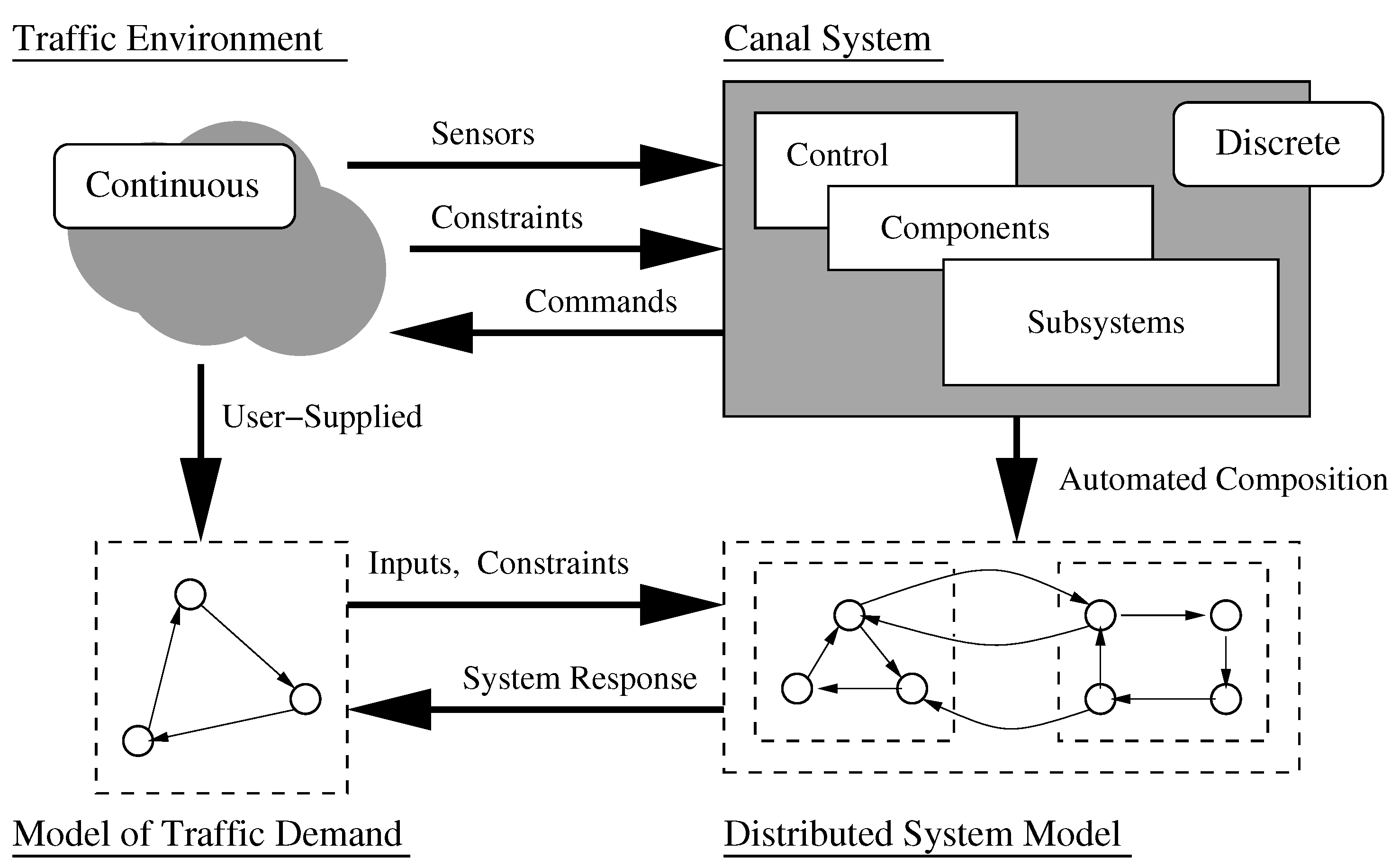
Figure 2 shows, for example, a process modeling framework for the systematic assembly of a transportation (canal) system and its interaction with the surrounding environment. A reasonable approach for representing canal system behaviors is to assume that each subsystem (or component) has behavior that can be modeled as finite state machine and will be implemented as a finite state process. Architecture-level models of behavior will be viewed as a network of interacting finite state machine processes, and will be synthesized through a bottom-up composition of subsystem- and component-level behaviors.
2.2. Finite State Automata
Automata are simple, but useful, models of computation where behavior includes the notions of state, transitions between states, and start and end states, but removes from consideration notions of memory, variables, commands and expressions. From a systems modeling point of view, the use of automata in behavior models is attractive because sophisticated models of behavior can be systematically assembled into networks and hierarchies of interacting processes, each defined by a simplified finite state machine representation (or automata). This strategy of model assembly works because automata constructions operate on automata yielding new automata and, in fact, provide closure under the operations of union, intersection, complement and concatenation [
13]. For example, a product construction takes two deterministic finite state automata (DFAs) and generates a single DFA that conceptually runs its two component machines in parallel on the same input string.
2.3. Labeled Transition Systems
Definition 1. A labeled transition system (LTS) process, P, contains: (1) All of the states that a process may reach; and (2) All of the transitions it may perform. In mathematical terms, a LTS process consists of a quadruple where,
- 1
S is the set of states;
- 2
A = , where is the communication alphabet of P which does not contain the internal action τ.
- 3
denotes a transition relation.
- 4
q is a state in S which indicates the initial state of P.
Process behavior is defined through sequences of actions (or transitions) a process may perform. The set of actions relevant to the behavioral description of a process P is called its alphabet, and it is denoted . We use the symbol to represent an error state against which safety property violations may be tested (details to follow). A process that transitions into an error state may participate in no further transitions (i.e., the process deadlocks). The labeled transition system (LTS) for process P = transits into another LTS of with an action if an only if and where is an error (or deadlock) state. Mathematically we can state if and only if and .
Composition of Labeled Transition Processes. Given two labeled transition systems
and
, we denote the parallel composition
as the LTS that synchronizes actions common to both processes and interleaves the remaining actions. By extension the architectural-level behavior model is defined by:
where
is the finite state model for the
i-th component among
n interacting components. Joint behavior is the result of all LTSs executing asynchronously, but synchronizing on all shared message labels. At the component level, the nodes of a labeled transition system represent states the component can be in. At the architecture level, labeled transition system nodes represent system-level states which, in turn, correspond to specific combinations of component-level states.
Table 1 provides a formal definition of parallel composition of processes and their corresponding algebraic properties. The alphabet for
is given by the union of alphabets for
and
. Equation (5) through (10) define the transitional semantics of the parallel composition operator. The composition operator is both commutative and associative, as indicated in Equations (9) and (10). Finally, it is important to note that the rules require that a composite process be trapped in an error state
if any of its constituent processes is trapped.
Systematic Removal of Detail from Behavior Models. From a modeling and design standpoint, the alphabet of a behavior model needs to achieve the dual objectives of supporting the required decision making, while also working to keep a model’s size tractable. Thus, a key aspect of alphabet design is to ignore actions and properties not immediately relevant to a particular activity (or set of activities). Observability of actions in a process can be controlled by a restriction operator ↑. In particular, the notation
. represents the process projected from
P in which only the actions in the set
L are observable. Equations (1) through (4) in
Table 1 define the transitional semantics of the restriction operator. As a case in point, Equation (1) should be read as follows: Suppose that process P transitions into
through the application of action a. If action a belongs to the set of observable actions in L (i.e., a
) and
is not a deadlock state (i.e.,
), then action a will transition
into
.
2.4. Model Checking and Property Validation
Model Checking. Given a finite-state model of a system and a formal property, model checking procedures [
23] systematically check whether the property holds for that model. Model checking begins with two activities that can occur concurrently.
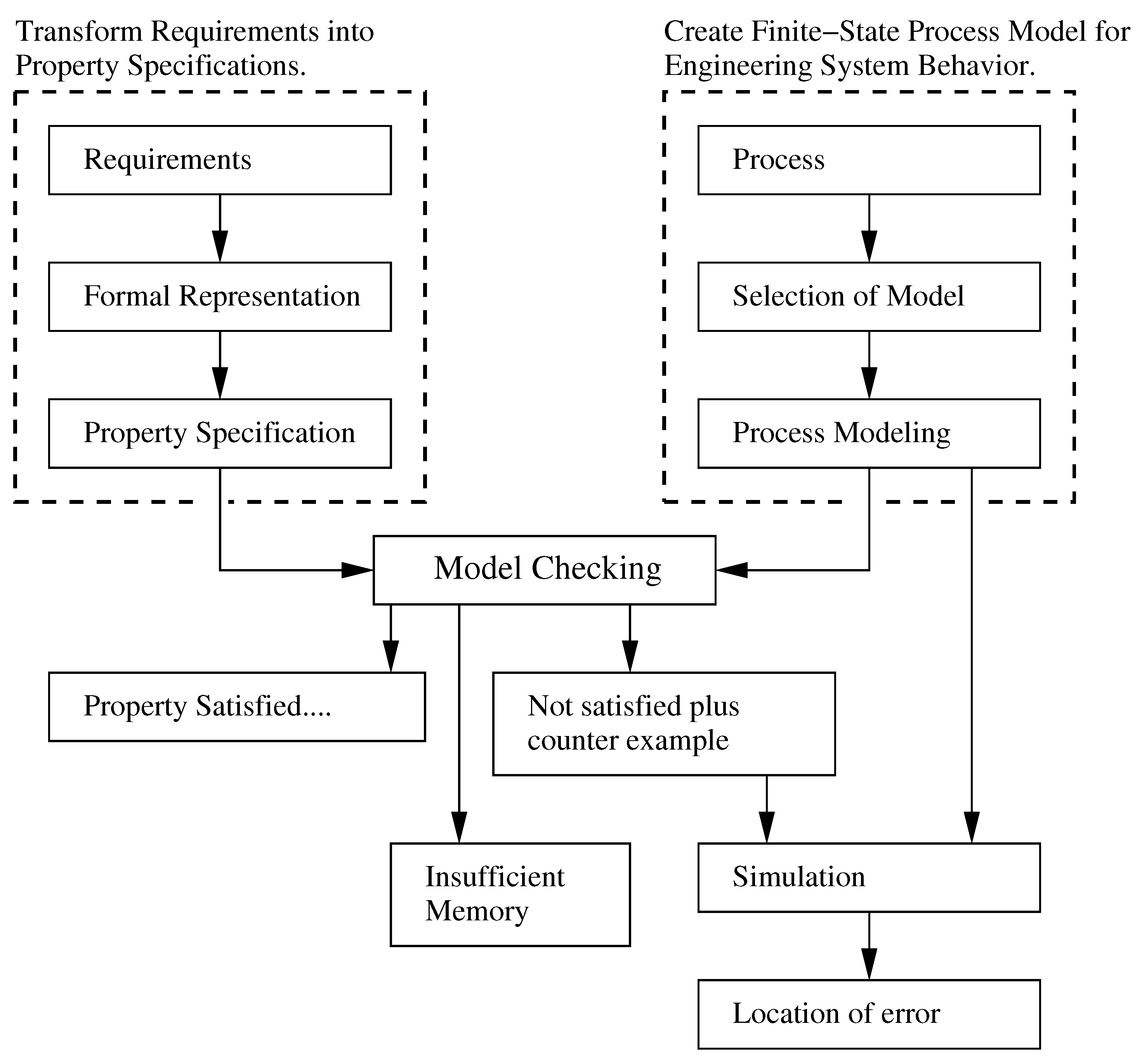
As shown along the left-hand side of
Figure 3, informal requirements are transformed into formal specifications describing properties that any acceptable system implementation will satisfy. A property is an attribute of a process that is true for every possible execution of that process. Typical properties are of a qualitative nature (e.g., will the system ever reach a situation for which there is no pathway forward?). Then as illustrated on the right-hand side of
Figure 3, a finite state process model for behavior of the engineering system is assembled.
To answer the above-mentioned questions in a precise and unambiguous manner, the system behavior model must be sufficiently detailed, but for computational purposes, not too complex. Model checking procedures examine property specifications with respect to process models. Three outcome are possible:
The property specification is satisfied,
The property specification fails,
The model checking procedure fails because of insufficient computer memory.
When a property specification fails, the result is accompanied by a counter example. In most cases, the underlying cause can be identified through detailed analysis (i.e., simulation) of actions in the counter example. Generally this will lead to refinement in one or more of the model, the design or the property. The only practical way of dealing with “insufficient memory” is to reduce the size of the model and try again. Iterations of model checking continue until all of the property specification violations have been repaired.
Framework for Compositional Validation of System Behavior. A good system design satisfies safety properties and exhibits liveliness (or progress). Safety violations in behavior modeling correspond to undesirable sequences of actions. For example, two systems should not simultaneously attempt to acquire a shared resource. A safety violation will also occur if a state becomes blocked and cannot make further progress (i.e., it becomes deadlocked). Liveliness/progress concerns include the ability of a process to eventually terminate and/or reach a critical state (or outcome) in its execution.
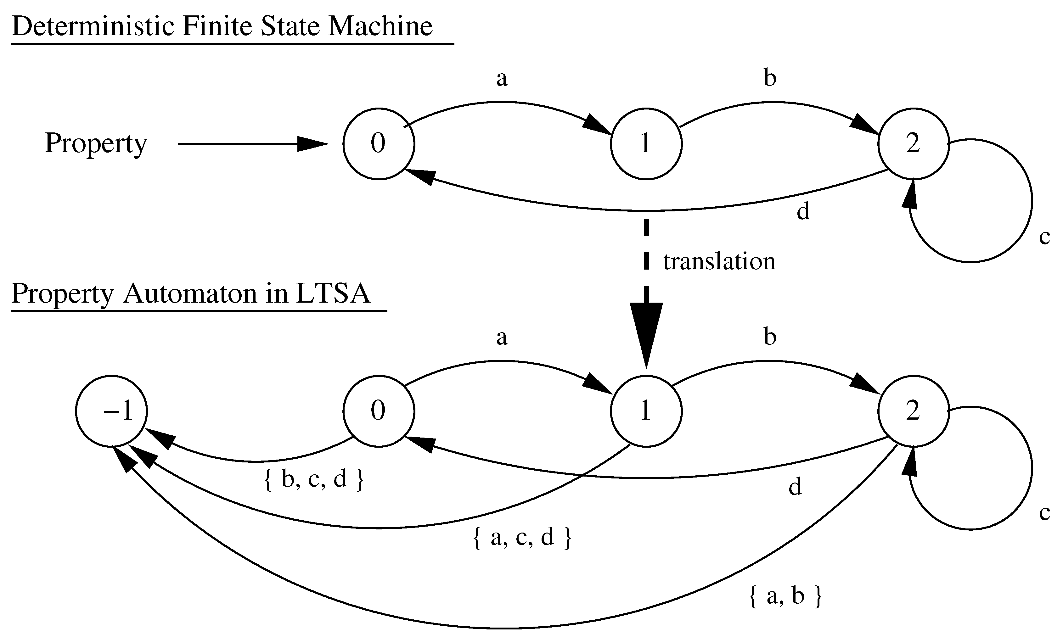
Safety properties are specified in FSP as deterministic property automata. Each property automaton specifies the set of feasible execution sequences over the actions (transitions) that correspond to a safety property of interest.
The upper diagram in
Figure 4 shows, for example, a property where action
a must be followed by action
b which, in turn, can be followed by a sequence of action
c or action
d. LTSA creates an image automaton that captures the prescribed property automaton and adds to it possible violations leading to an error state. Now suppose that action
a has just completed. If the behavior model allows for any action other than
b (i.e., the set of actions {
a,
c,
d}), then the property automaton will transition to the error state. Next, we note from
Table 1 that the (error)
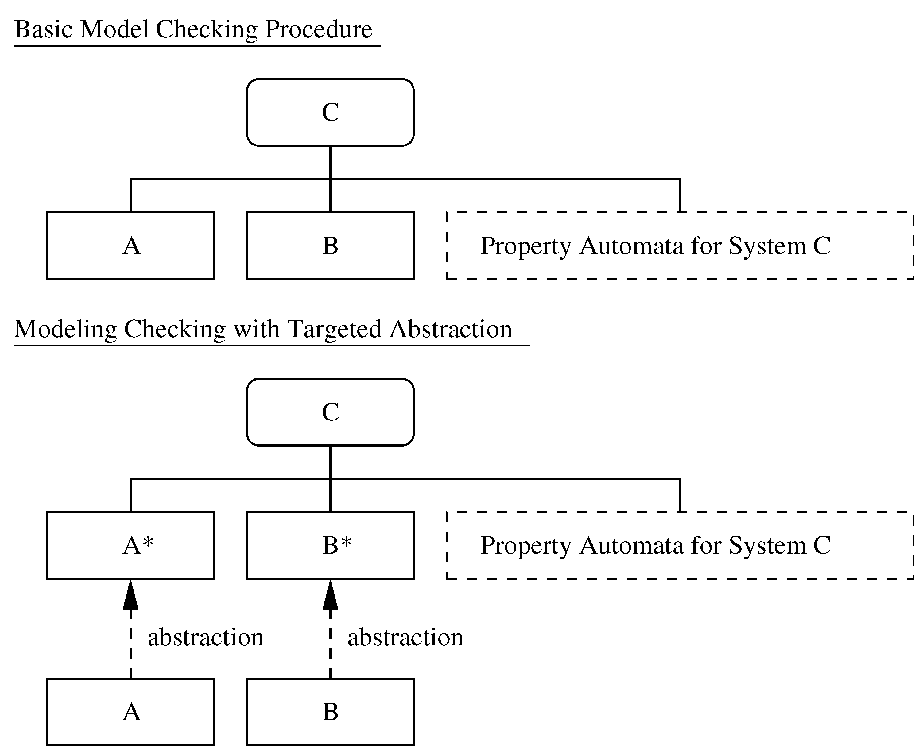
state is preserved by both the restriction and composition operators. This property allows for a validation procedure that is remarkably straightforward. All that we have to do is compose the property automaton with the system description process—see, for example, the upper half of
Figure 5—and look for the existence of
(an error state) in the global LTS. If the composed process contains an error state, then the safety property is violated. Otherwise, the safety property is satisfied. For a mathematical treatment of property automata and safety operations, we refer the interested reader to Austin and Johnson [
24] and references therein.
Progress Properties and Analysis. As already noted, a progress property asserts that it is always the case that an action—usually, a desirable action—is eventually executed.
Progress analysis begins with a search for sets of terminal states; that is, sets of states where every state is reachable from every other state in the set via one or more transitions, and, there are no transitions from within the set to any state outside the set. Given fair choice, each terminal set of states represents an execution where each transition is executed infinitely often. With this framework in place, checking that a progress property holds reduces to the problem of checking that the progress actions are part of each terminal set [
25].
3. Targeted Abstraction and Viewpoint-Action-Process Traceability
The well known difficulty in using exhaustive search techniques for validation of concurrent system behaviors is that size of the state space expands exponentially with increasing numbers of underlying processes (and actions therein). This occurs because interleaving models for asynchronous system behavior allow concurrent events to be ordered arbitrarily and, as such, events are interleaved in all possible ways. For a model where n transitions can occur concurrently, and are primarily autonomous, there are different orderings and different system states. Only minor reductions in the size of composed processes will occur through constraints associated with synchronized actions.
For the behavior modeling and verification for distributed systems operations, the central challenge is not composition of the behaviors, but design of strategies that:
Use decomposition to organize design concerns, viewpoints, and processes into a hierarchy, and
Employ abstraction to eliminate details of a behavior model that are of no importance when evaluating system functionality with respect to a specific set of design concerns.
To this end, our goal is to support decision making with process models and verification procedures of minimal size.
3.1. Related Work in State Graph Reduction
Techniques for reducing the size and complexity of processes can be classified into two broad categories:
Strategies for partial order reduction are based on the dependency relations that exist between the transitions of a system, and the observation that two interleavings can be regarded as equivalent if one can be obtained from the other by swapping adjacent, non-conflicting (independent) execution steps. Algorithms for partial order reduction explore at least one trace from each (so-called Mazurkiewicz) equivalence class [
29]. Thus, partial order reduction provides a full coverage of all behaviors that can occur in any interleaving, even though it explores only a subset of traces. Simplified exploration of the state space can also occur through consideration of only those process interleavings that are relevant to a specific property being validated [
23,
30,
31,
32,
33]. Solution strategies include use of bounded and context-dependent searches [
34,
35], modified semantics and/or identification of dependencies among transitions [
28,
36]. Recent advances include dynamic approaches to partial ordering [
37,
38] and use of annotations in the analysis of trace spaces. While the general state space exploration problem is NP complete, Chatterjee et al. [
39] have shown for acyclic trace structures, it is possible to explore the state space with polynomial effort.
3.2. Compositional Reduction Analysis
Procedures for compositional reduction analysis are ideally suited to systems that can be naturally organized into a hierarchy of behavior modules. The simplification of behavior models occurs through the hiding of as many internal actions as possible in each subsystem, and through the tendency of safety properties to be locally checkable. The lower half of
Figure 5 shows, for example, a scenario where behavior of process C corresponds to the composition of processes A and B (i.e., A ∥ B). If process C is too large (i.e., requires resources beyond the capability of the environment within which it is executing), then the composition is simplified by removing actions internal to the process module (i.e.,
and
). Safety properties are then validated against the simplified composition (
). Progress properties rely on a set of actions being activated at a particular level of detail; similar reductions in complexity can occur when lower level actions are removed from consideration.
Now let us assume that a violation has been detected and that a designer wishes know the cause of the violation. This task is facilitated if debugging traces show as much detail as possible. These dual criteria point to a natural tension in the methodology. We wish, on one hand, to simplify models through removal of details. Yet at the same time, we need to maximize the availability of information for debugging purposes.
3.3. Viewpoint-Action-Process Traceability
Viewpoints serve two purposes. First, they motivate the generation of abstractions relative to a design concern (e.g., safety and progress checks). Their second purpose is one of simplification. By systematically removing actions that are not related to a design decision, models can be trimmed to minimize their complexity (e.g., generation of simplified abstractions for “higher-level” modeling).
We propose that process validation procedures can be simplified through: (1) Systematic organization of design concerns, viewpoints and processes into hierarchies (system decomposition), and (2) Reduction by compositional minimization (abstraction). In a departure from past work, modules will have boundaries (i.e., notions of inside and outside) that depend on a design viewpoint (or family of design concerns). They will be organized into hierarchies; as such, low-level processes of minimal size can be composed into higher-level processes that will be validated against the concerns of a specific viewpoint.
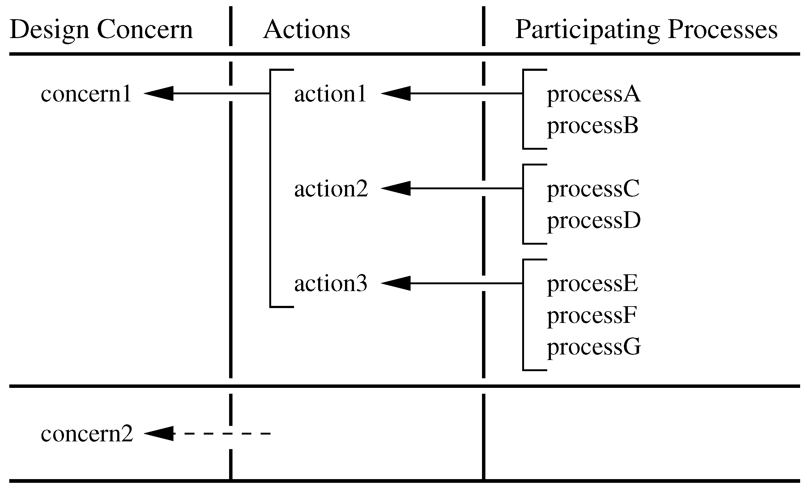
To streamline this process we propose the concept of viewpoint-action-process traceability as a means of representing connectivity between the formal description of a design concern (viewpoint), sets of actions, and their participating processes. The step-by-step procedure is as follows:
For each design concern, identify the set of actions that are part of the associated behavior.
Identify the processes that participate in the execution of these actions.
Remove from the behavior, actions that are not associated with the design concerns or interactions among the participating processes.
This procedure lends itself to a tabular display of traceability linkages, as illustrated in
Figure 6. After each application of viewpoint-action-process traceability, we also immediately minimize the size of all intermediate results. As we will see in the application below, the result is a computational procedure where process models achieve their required functionality, but may have a size that is orders of magnitude smaller than in the all-in-one approach to composition.
4. Case Study A: Formal Validation of a Behavior Model for Polite Conversation
To see how compositional approaches to behavior modeling work on a small-scale problem, let us consider a simple scenario where two people, Jack and Diane, meet for coffee and polite conversation. The goal is to devise a system-level behavior model where both Jack and Diane talk, but neither party dominates the conversation. The properties of this behavior model will be formally checked.
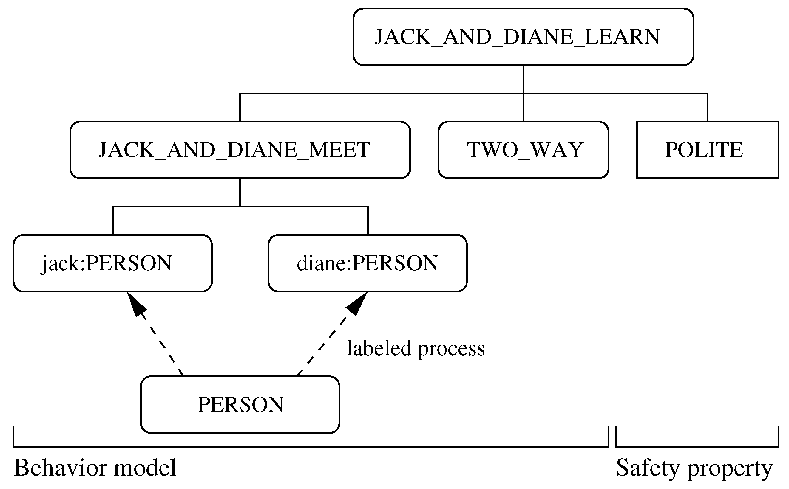
The script of code shown in
Table 2 systematically assembles the hierarchy of processes shown in
Figure 7. The key activities in development of the behavior model are as follows:
Identify main events, actions and interactions,
Identify main component-level processes,
Identify and define properties of interest, and
Compose component-level behaviors into a model of architectural-level behavior.
The behavior modeling process begins with the definition of a generic PERSON, who can talk and drink, or simply wait and then drink. LTSA requires that processes operate continuously. Thus, if talk and drink are actions, and PERSON is a process, then the fragment of FSP code talk -> drink -> PERSON describes a process that initially engages in the action talk, then the action drink, and then behaves exactly as prescribed by PERSON. In practical terms, an action might be a communication, a signal, or perhaps, traditional execution of a task. Jack and Diane are simply labeled instances of the process PERSON (i.e., with the notation jack:PERSON and diane:PERSON).
The composed process JACK_AND_DIANE_MEET captures all of the possible sequences of actions that can occur. This under-constrained model allows, for example, for one person to talk and talk and talk, with the other person not getting a word in edgewise. The keyword minimal minimizes the size of the composed process from nine states to four states.
To improve the meeting, the
TWO_WAY process places a constraint on the conversation, in particular, that Jack and Diane need to engage in alternate talking. The revised meeting model is,
||JACK_AND_DIANE_LEARN = ( JACK_AND_DIANE_MEET || TWO_WAY ).
However, how do we know that this actually worked? To check that the composed model is in fact what we want, we can define the property
POLITE, i.e.,
property POLITE = ( jack.talk -> diane.talk -> POLITE ).
and then compose
POLITE with
JACK_AND_DIANE_LEARN. The FSP notation
jack.talk/diane.wait and
diane.talk/jack.wait changes (i.e., relabels) the action notation
diane.wait to
jack.talk, and
jackwait to
diane.talk, respectively, thereby simplifying complexity of the behavior model.
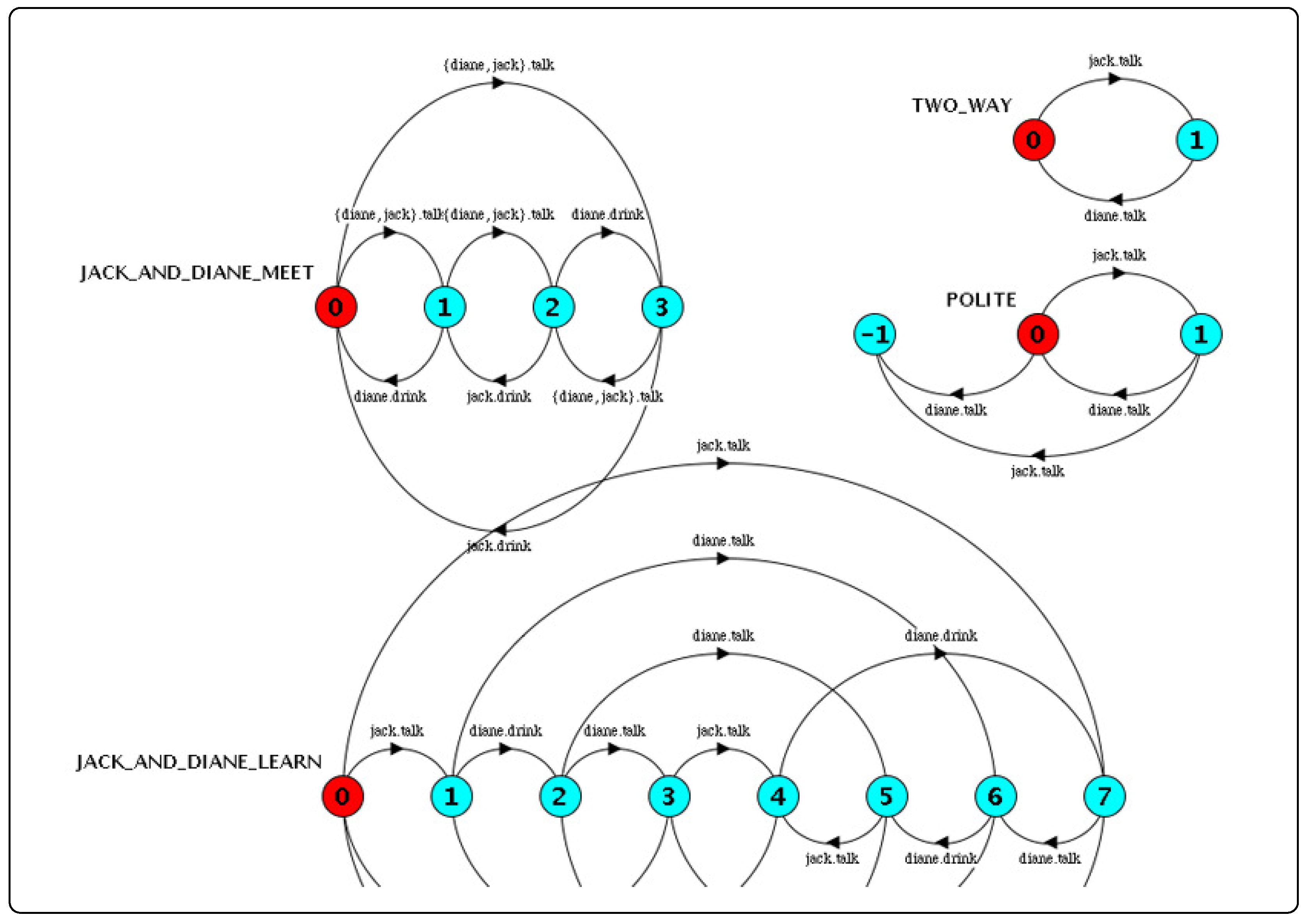
Figure 8 shows the LTSs for each of the constituent processes including
POLITE. Notice that POLITE will transition to an error state if Diane talks more than once or, alternatively, Jack talks more than once. If the composed process
( JACK_AND_DIANE_MEET || TWO_WAY || POLITE )
contains any of these sequences, then it too will also have an error state indicating that our model of behavior is not polite. As it turns out, the composed process (see
Figure 8) is free of error states and the
POLITE property is satisfied. The progress checks generate
 Progress Check...
 -- States: 8 Transitions: 16 Memory used: 1951K
 No progress violations detected.
 Progress Check in: 40ms
indicating that hoth Jack and Diane engage in polite conversation.
5. Case Study B: Compositional Behavior Modeling and Validation of Waterway System Operations
We now exercise the proposed methodology by working step-by-step through the model-based design and formal validation of behaviors for collections of ships traversing a simplified model of the Panama Canal, an 80 km passageway that joins the Atlantic and Pacific Oceans at one of the narrowest saddles of the isthmus [
40]. A ship passing through the canal will ascend through a set of locks, traverse Lake Gatun, and then descend through the lock system on the other side.
Solutions to this problem are complicated by the large number of concurrent processes (e.g., ship operations, pumps, gates, lockset scheduler) defining component- and system-level behavior. Part of this problem can be solved through hierarchal decomposition of processes, with each level in the hierarchy dealing with a specific set of design concerns. Decomposition does not solve the problem completely, however, because naive approaches to the parallel composition of processes quickly become computationally intractable. To overcome these limitations, we apply viewpoint-action-process mechanisms, thereby abstracting from the composition, actions and groups of actions that are irrelevant to decisions associated with a particular viewpoint. Our goals is to devise strategies where:
Behavior models focus on the modeling of ship movements, and
The size of the canal system processes models remains constant, regardless of the number of ships waiting to traverse the canal system.
Constraints on behavior will ensure that when ships arrive at a lockset they are handled on a first-come, first-served basis. Complete details of the input files for these case studies can be found in the appendices of Austin and Johnson [
24].
5.1. Framework for Multi-Layer Behavior Model Development
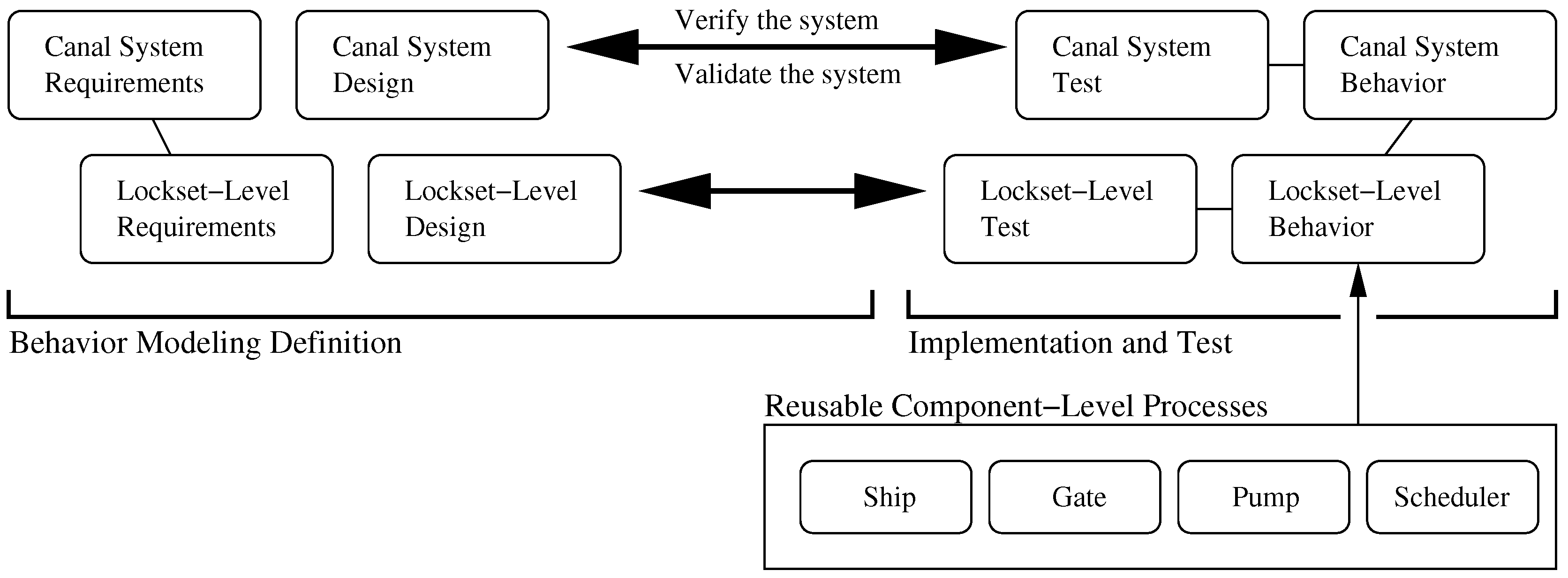
The step-by-step procedure for design, implementation and validation of behavior for Panama Canal operations is simplified through a top-down decomposition of concerns (i.e., requirements and design specifications) followed by a bottom-up assembly of process models and testing/validation.
Figure 9 and
Figure 10 show the two-level V-model of system development assumed for this study, and an elevation view of the lockset, and component- and lockset-level process architectures. In an extension of the procedure described in Case Study A, behavior models are organized into a two-level process hierarchy. For the lockset-level behavior, localized control will be employed for the safe, fair, and efficient scheduling of ship transit operations. A scheduler process will receive east- and west-bound transit requests and schedule transit operations in a manner consistent with the task planner. The scheduler will also communicate permission for a particular ship to access the canal system to the passageway controllers. These lower level processes will be responsible for synchronizing low level activities such as incremental ship movements with pump and gate operations. At the system level, the primary design concerns include provision for: (1) Adjustment of operations during emergency and/or /maintenance events and; (2) Cooperation of asynchronous lockset-level behaviors to ensure efficient transit of ships through the canal system. Because emergency and/or maintenance events will be detected at the lockset level, but controlled by a system-wide manager process, system-level canal behavior will be defined by a network of partially synchronized processes.
Lockset- and Canal-Level Requirements. The functional requirements associated with lockset-level concerns are as follows:
At any point in time, the scheduler must assign no more than one ship to a lockset;
All ships must request transit before they can acquire access to a lockset. They must acquire access to the lockset before they depart.
Flooding must be prevented. A gate must not open until water levels on both sides of the gate have been equalized; and
All ships that request passage through the lockset must eventually depart the lockset.
At the canal system level, functional requirements include:
When an emergency or maintenance occurs, all incoming canal traffic must be halted. Traffic can resume after the emergency (or maintenance) has been cleared (or repaired).
All east- and west-bound ships must be guaranteed to reach the Atlantic and Pacific Oceans respectively.
Top-Down Specification of System Functionality. In the simplest terms possible, a ship will transit a two-stage lockset by working through the following step-by-step procedure:
Request permission to pass through the lockset,
Wait in the arrival area,
Acquire permission to enter the lockset,
Enter lock 1,
Enter lock 2, and
Depart.
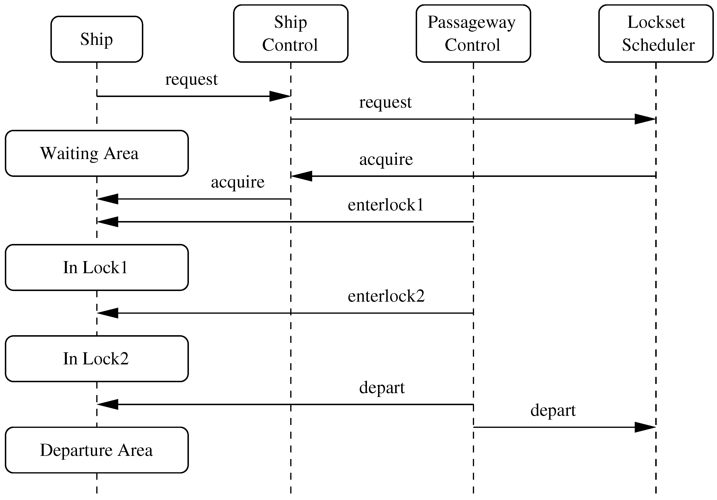
The execution of Steps 1–6 implies a specific sequencing of messages among ship, ship control, passageway control and scheduler processes. The key communications among processes are as follows:
The Ship sends a message to the ship control requesting permission to transit the lockset. It then joins a queue of waiting ships in the arrival area.
At some point later in time, the scheduler will send a message to the Ship and Ship Control processes that it may acquire the resources of the lockset.
The passageway controller commands the ship to enter lock 1 (i.e., enterlock1).
The passageway controller commands the ship to enter lock 2 (i.e., enterlock2).
The passageway controller commands the ship to exit lock 2 and depart (i.e., depart).
The passageway controller informs the lockset scheduler that the ship has departed lock 2.
Figure 11 provides a graphical summary of this sequence of message passing. The
Ship time line shows that as a vessel moves through the lockset system it will actually progress through four spatial states; an arrival area, area lock1, area lock2, and a departure area. For a ship ascending the lockset, lock1 will be the lower lock. For a ship descending the lockset, lock1 will be the upper lock. This subtle difference in context, coupled with the details of raising/lowering water levels and opening/closing gates requires the implementation of two passageway controllers – one for ascending the lockset and a second for descending the lockset.
Simplified Model of Ship Behavior. The sequence of messages in
Figure 11 suggests that basic ship behavior can be defined by the circular process:
SHIP = (request -> acquire -> enterlock1 -> enterlock2 ->. depart -> SHIP). Shipping personnel are certainly involved in the execution of the actions
request,
acquire and
depart. However, the actions
enterlock1 and
enterlock2 are internal to the lockset itself. Hence, a much better solution is to simply define the ship behavior as
SHIP = (request -> acquire -> depart -> SHIP), and then design the scheduler and passageway control processes (details to follow) to properly sequence
enterlock1 and
enterlock2 among other low-level actions for pump and gateway control.
5.2. Bottom-Up Composition of Travel Demand and Lockset-Level Behavior
Figure 10 shows the process architecture for the implementation of lockset-level behavior. One process hierarchy is assembled for the lockset system itself – it is the composition of scheduler, passageway control, ship control, gate, pump and lock processes. A second process hierarchy is assembled for the east- and west-bound traffic demand. The complete model of lockset behavior corresponds to the parallel composition of lockset and traffic demand process models, i.e.,
|| LOCKSET_BEHAVIOR = ( LOCKSET_SYSTEM || TRAFFIC_DEMAND ).
Model of Lockset-Level Traffic Demand. Travel demand processes are defined for convoys of east- and west-bound ships (i.e., processes
EASTBOUND_SHIPS and
WESTBOUND_SHIPS) and circular queuing processes to ensure that transit requests are handled in the same order in which they are made, i.e.,
 // Simplified model of a single ship passing through the lock system.

    SHIP = ( request -> acquire -> depart -> SHIP ).

    ||EASTBOUND_SHIPS = ( [i:S]:(east:SHIP) ).
    ||WESTBOUND_SHIPS = ( [i:S]:(west:SHIP) ).

 // Create circular queue of east- and west-bound transit requests.

    EASTBOUND_REQUESTS = QUEUE1 [1],
    QUEUE1[i:S] = ( [i].east.request -> QUEUE1 [ i%NoShips + 1] ).
    WESTBOUND_REQUESTS = QUEUE2 [1],
    QUEUE2[i:S] = ( [i].west.request -> QUEUE2 [ i%NoShips + 1] ).

    ||EASTBOUND_TRAFFIC = ( EASTBOUND_SHIPS || EASTBOUND_REQUESTS ).
    ||WESTBOUND_TRAFFIC = ( WESTBOUND_SHIPS || WESTBOUND_REQUESTS ).

 // Compose models of East- and West-bound traffic ....

    ||TRAFFIC_DEMAND = ( EASTBOUND_TRAFFIC || WESTBOUND_TRAFFIC ).
The command SHIP = ( request -> acquire -> depart -> SHIP ) defines a single process for a sequence of actions defining ship behavior. Next, the lines EASTBOUND_SHIPS = ( [i:S]:(east:SHIP) ) and WESTBOUND_SHIPS = ( [i:S]:(west:SHIP) ) create arrays of S ships traveling in West- and East-bound directions. It is important to notice that from a ship’s point of view, acquiring access to the lock system is what matters – once that is achieved, the next significant action is departure from the lock system. Ships do not need to know (or care) about the internal details of the lock system operations. Finally, the overall traffic demand model is the composition of east- and west-bound traffic demands.
First-cut Composition of Lockset-System Behavior. In this first-cut implementation we simply compile the scheduler, west- and east-bound ship control, passage control, and gate and pump system processes together, then at the last point possible attempt to minimize the process size. As illustrated in
Figure 10, the lockset contains three gates (tagged, low, middle, and high) and two pumps (tagged low and high). Gate and pump processes open and close gates and raise and lower water levels. Ship controller processes are shared resources responsible for maintaining order between incoming requests and access to the lockset.
Design of the passageway control and lockset scheduler processes is the most interesting part of the lockset behavior model formulation. Passageway control is responsible for sequencing the ship and lockset actions (e.g., coordination of gate and pump operations) while a ship is inside the lockset. The lockset scheduler process receives transit requests from east- and west-bound ships and at some later point issues permission to the ship controllers to begin the transit of a particular ship. The scheduler process needs to take into account the number of ships waiting to transit the canal in either direction, and implement an appropriate policy of fairness. Moreover, the scheduler process should also take the correct action without the forced imposition of physical constraints (e.g., a constraint that says, at most, only one ship can occupy the lockset).
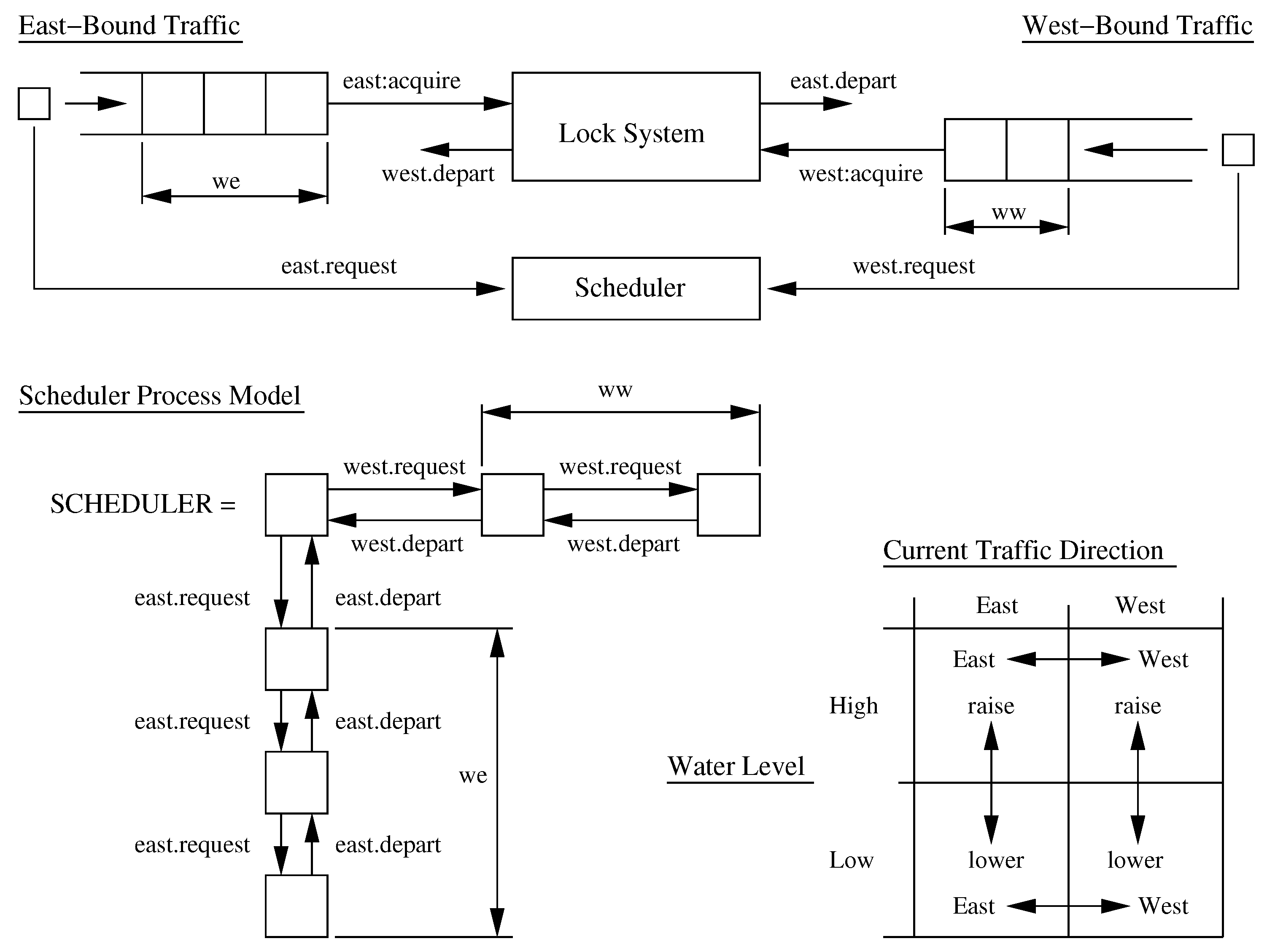
As illustrated in
Figure 12, the scheduler is implemented as a four-dimensional array of processes. The first and second dimensions keep track of the number of ships waiting for transit in the east- and west-bound directions (maximum value is
NoShips). Variable we = number of east-bound ships waiting (0..NoShips). Variable ww = number of west-bound ships waiting (0..NoShips). Dimensions three and four keep track of the current traffic direction (td = East or West) and water level (wl = Low or High). At a glance it would seem that the ship control processes are not needed because their operations are completely covered by the scheduler process. The important distinction and, hence, their roles lie in their view of the ships. Ship controllers track the progress of specific ships by name (e.g.,
[1].east). The lockset scheduler’s relationship with ships is more abstract. It simply keeps track of incoming requests and provides permission for east- and west-bound ships to acquire the locksets resources.
5.3. Preliminary Results
Table 3 summarizes the number of states in the traffic demand and lockset system (and select lockset subsystem) processes as a function of the number of east- and west-bound ships. On an Apple Macbook Pro with 4GB of memory, the problem formulation becomes computationally intractable when three east-bound ships and three west-bound ships are traversing the canal.
To overcome this problem we need to be much smarter in controlling the size of participating processes by only including those actions (and critical dependencies) that are tied to a particular viewpoint of system functionality.
5.4. Composition of Simplified Lockset-Level Behavior
The composition of simplified lockset-level behavior models takes advantage of the natural hierarchy of canal system behavior models, and only considers actions that are directly related to a specific decision or behavior modeling viewpoint. Viewpoint driven models can be assembled for: (1) simplified modeling of ship movement (i.e., a minimal version of LOCK_SYSTEM); (2) examination of passageway safety against flooding (i.e., LOWER_PUMPS and RAISE_PUMPS); and (3) passageway occupancy (i.e., LOCK_OCCUPANCY). All three viewpoints can be evaluated through the composition of SCHEDULER, SHIPCONTROL and PASSAGECONTROL processes (and variations thereof) in a manner consist with the process hierarchy.
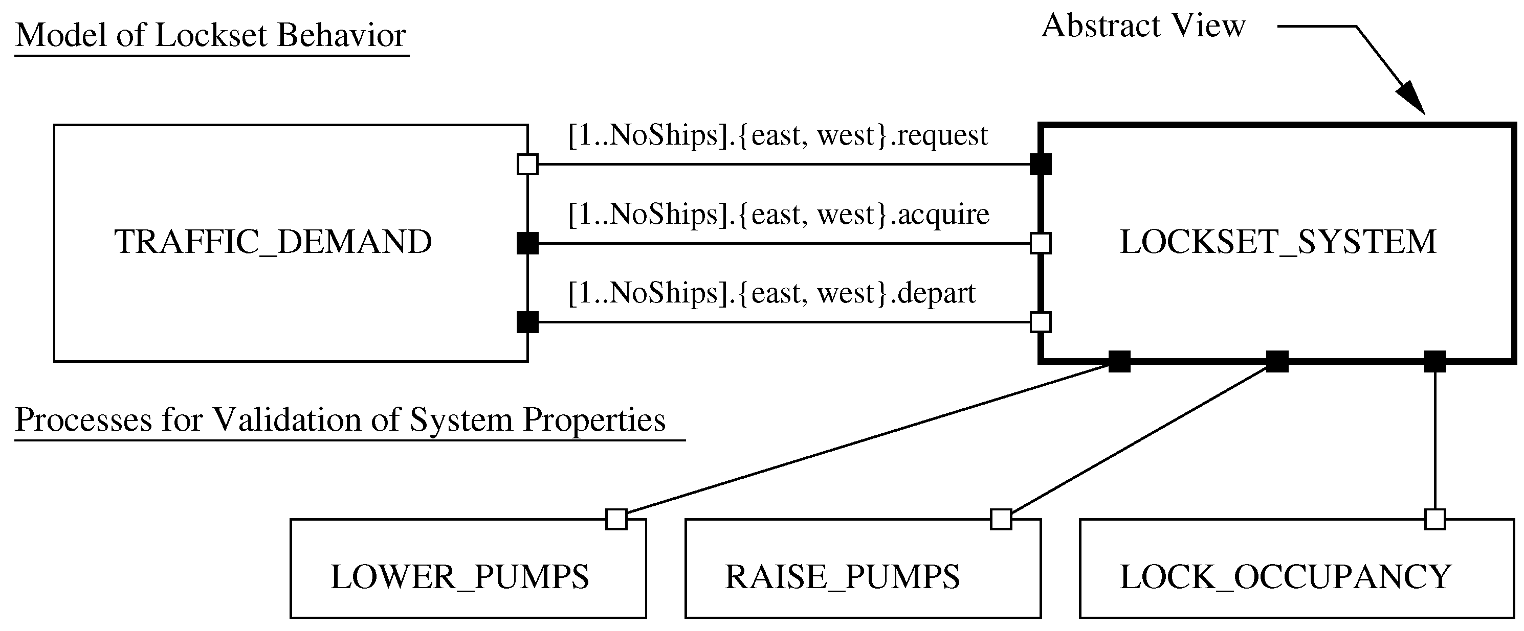
Figure 13 and
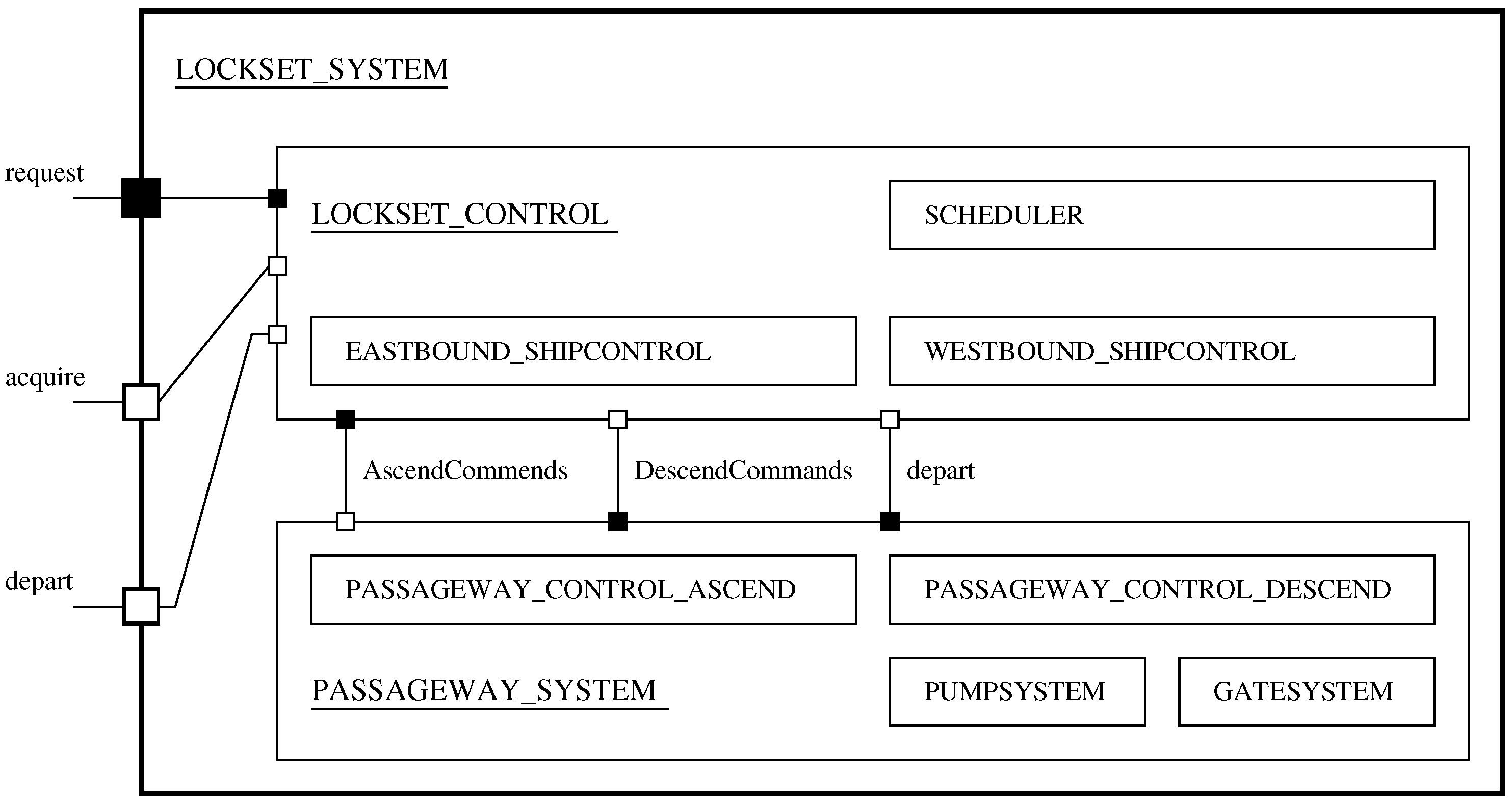
Figure 14 show abstract and detailed process hierarchy views of: (1) the traffic demands process interacting with the lockset system process; (2) the lockset system process organized into lockset control and passageway system process hierarchies; and (3) processes for compositional validation of lockset behavior properties. We employ white and black dots to show dependencies between the process hierarchies. The
LOCKSET_SYSTEM and
TRAFFIC_DEMAND processes are connected by request, acquire, and depart actions. White and black box notation shows dependencies of the actions. For example, a ship will request transit of the lock system—the request is the requirement, the lockset system provides for processing of the request. In the initial formulation, models of lockset system behavior were defined through an “all-in-one composition” of seven processes (i.e.,
SCHEDULER,
WESTBOUND_SHIPCONTROL and so forth). Now, assembly of the model occurs over three layers:
- 1.
LOCKSET_CONTROL is the composition of scheduler and east- and west-bound ship controls,
- 2.
PASSAGEWAY_SYSTEM is the composition of ascend and descend passageway processes, plus processes for the pump and gate systems, and
- 3.
Gate and pump systems are defined through the composition of individual pump and gate processes (these details are not shown in
Figure 14).
5.5. Application of Viewpoint-Action-Process Traceability
To systematically determine which parts of the behavior model can be omitted without affecting a pre-defined viewpoint, the process-action dependency is reversed. For each action (or, when appropriate, group of actions) a list of dependent processes is assembled; an abbreviated example is shown
Table 4. Then, if a viewpoint is defined in terms of critical actions, traceability links can be established from a viewpoint to dependent actions to dependent processes.
As a starting point, the lockset system behavior model is organized into a three layer hierarchy:
- 1.
The lockset control (i.e., ∥ LOCKSET_CONTROL) is composed from scheduler and west- and east-bound ship control processes.
- 2.
The passageway system (i.e., ∥ PASSAGEWAY_SYSTEM) is composed from west- and east-bound passageway control processes.
- 3.
Finally, lockset system behavior is assembled from the previously composed models for lockset control and the passageway system.
The underlying assumption in this model is that the processes LOCKSET_CONTROL and PASSAGEWAY_SYSTEM will be autonomous and only synchronize through shared actions. However, PASSAGEWAY_SYSTEM is not fully autonomous and, in fact, only responds to actions instigated by the scheduler (i.e., a master-slave relationship among processes). Moreover, although the east- and west-bound passageway processes share common actions (e.g., enterlock1, enterlock2) and theoretically synchronize on those actions, in practice, the scheduler process ensures that this never happens—the canal system is handling either an east-bound ship or a west-bound ship, but never east- and west-bound ships concurrently.
Sample Viewpoint (Composition of Behavior for Ship Movement). This viewpoint is motivated by the need for a simplified model of ship movement (i.e., a minimal version LOCK_SYSTEM), which downstream, will be suitable for inclusion in a canal-level model of behavior.
With the above-mentioned observations in place, the fragment of FSP code in
Table 5 implements and minimizes two versions of
LOCKSET_SYSTEM, one that includes
LOCKSET_CONTROL and
PASSAGEWAY_SYSTEM, and a second model based on
LOCKSET_CONTROL alone. The
PASSAGEWAY_SYSTEM process only carries forward actions that are critical to communication (i.e., resethigh, resetlow, ascend, descend), and/or the ship movement model (i.e., [S].east.depart, [S].west.depart). Finally, two versions of lockset behavior are composed.
Scalability of the Lockset Behavior Model.
Table 6 shows the size of the constituent processes as a function of NoShips. Not only are the process sizes several orders of magnitude smaller than in the initial formulation, but the computational procedure remains computationally tractable. The dual strategy of only including processes related to a specific decision, and incrementally assembling minimized processes has a huge impact on the computational feasibility of the analysis.
As a case in point, consider the PASSAGEWAY_SYSTEM model. Pump and gate processes each have two states. The decision to exclude three pump and two gate processes from the process model automatically reduces the size of the process model by a factor of 32. Still, when NoShips = 3, the unminimized PASSAGEWAY_SYSTEM model has 15 × 15 = 225 states. In contrast the minimized model has only 4 states and, in fact, this does not change with increasing numbers of ships.
5.6. Formal Validation of Lockset-Level Safety Concerns
As already noted, a safety property asserts that nothing bad happens during the canal operation. Safety checks are compositional in the sense that if there is no violation at a subsystem level, then there cannot be a violation when that subsystem is composed with other subsystems. At the lockset level we need to ensure that:
- 1.
The canal scheduler will not assign more than one ship to a lock, and
- 2.
Floods will be prevented by ensuring that a gate will not open before water levels on both side of the gate are equalized.
The short fragment of code in
Table 7 establishes a validation test for lock occupancy that says:
If a specific ship acquires resources of the lockset, then it needs to depart before another ship acquires the lockset.
Next, execution of the lock occupancy test is defined through composition of the lockset system with the lock occupancy property test. If the composed system (i.e.,
LOCK_OCCUPANCY_CHECK1) contains an error state (i.e., it fails), then there exists at least one pathway in the lockset system where an acquire operation is followed by a second acquire and/or a depart action is followed by a second depart operation. This interpretation of property satisfaction is allowed for via Equation (10) in
Table 1. For our model, however, the composed model is free of an error state and the test passes.
5.7. Composition and Validation of System-Level Behaviors
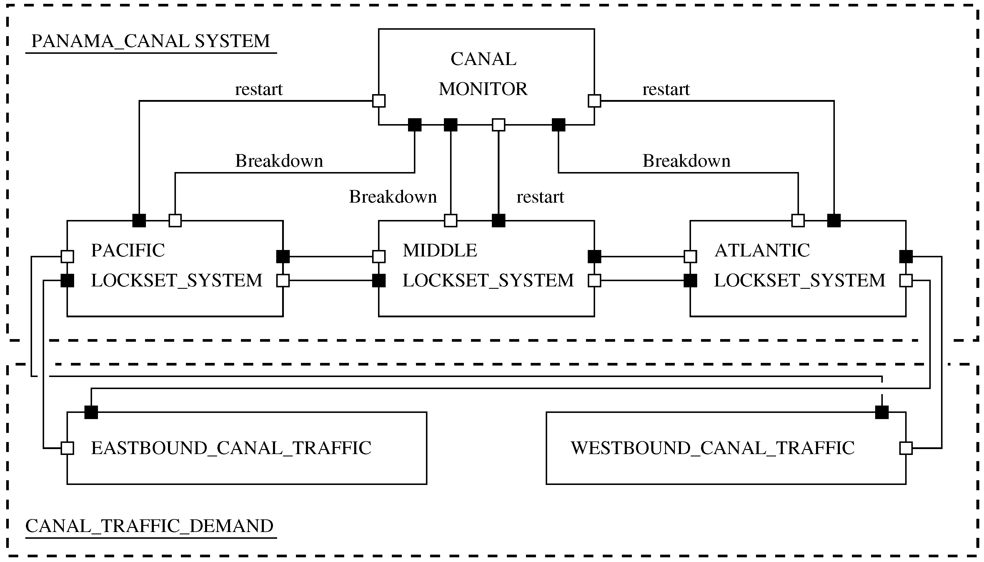
The Panama Canal System corresponds to a parallel composition of three lockset-level processes (i.e., the Pacific, Middle and Atlantic lockset systems) plus a control monitor process.
Figure 15 contain birds-eye views of canal-level transit operations and schematics of the process architecture for the full canal model (white dots represent requirements; black dots represent provisions). The canal traffic demand model will be a composition of
EASTBOUND and
WESTBOUND traffic. East-bound ships will ascend the Pacific and Middle locksets, cross lake Gatun (details not shown), and then descend the Atlantic lockset. West-bound ships will ascend and descend the Atlantic and Pacific and Middle locksets respectively. LTSA notation for the system-level traffic demand model is a straight forward extension of the lockset level behavior model. For example, the action
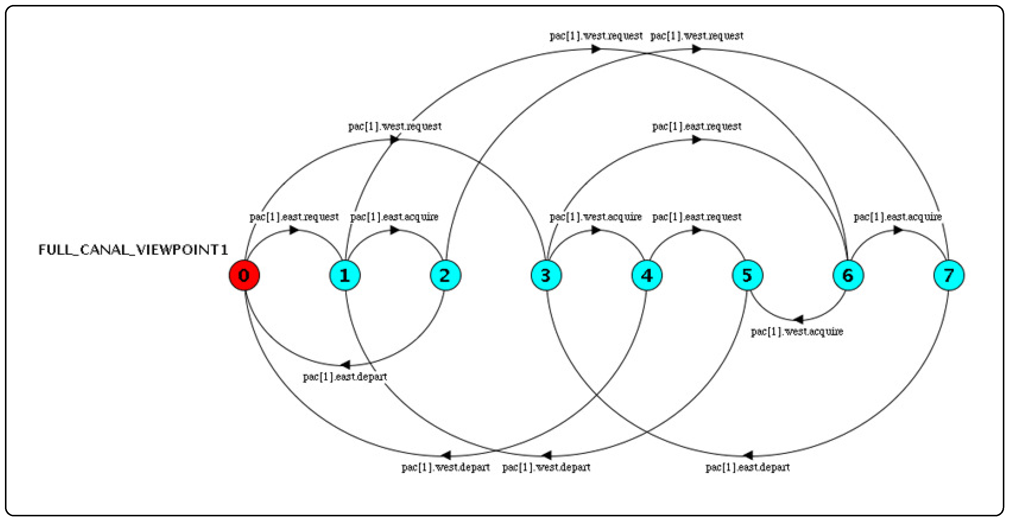
pac.[S].east.request indicates a request action by an eastbound ship to pass the Pacific Lockset. Using the strategy described in the previous section, simplified models of canal system behavior can be composed for a variety of viewpoints (e.g., traffic flow in one direction; behavior of a lockset within the canal system).
Figure 16 shows, for example, ship behavior at the Pacific Lockset when the number of east- and west-bound ships is one.
The two principle design concerns at the canal level are: (1) ensuring maintenance and emergency events are properly handled [
41,
42], and (2) ensuring progress checks at the lockset level propagate up to the canal level. We assume that emergency and maintenance events will both originate at the lockset-level (e.g., due to a collision). While emergency events can occur any time, maintenance can be scheduled to occur only when the lock is vacant. In either case, the lockset scheduler will inform the canal monitor of an event. The canal monitor will then mandate appropriate restrictions to transit operations in the east- and west- directions. Our preliminary implementation assumes that all incoming traffic will be immediately halted. All outgoing traffic will be allowed to continue onwards and clear the system.
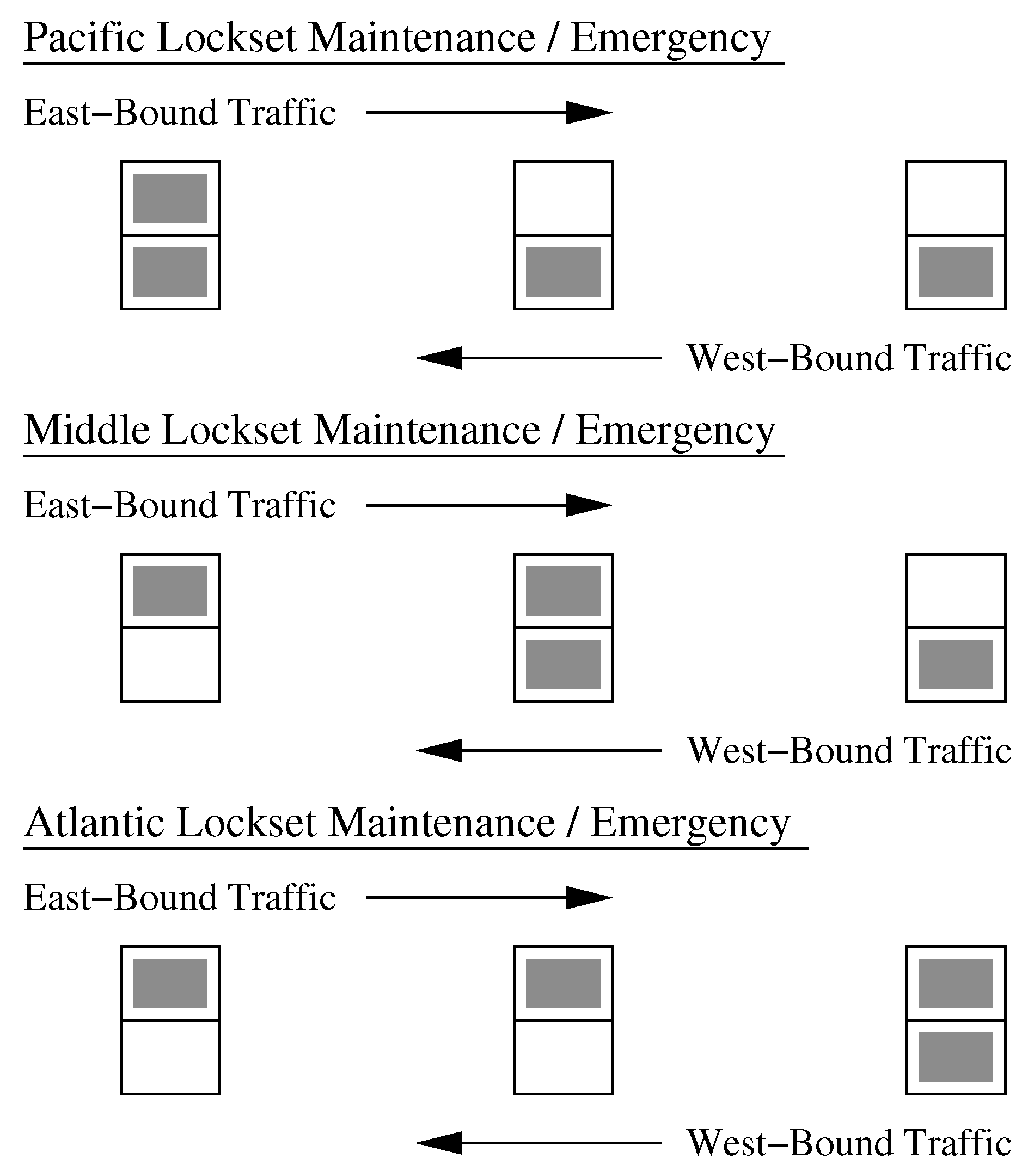
This policy leads to
Figure 17, a schematic of system-level response to maintenance and emergency events in the Pacific, Middle and Atlantic locksets. Schematics for the Pacific, Middle and Atlantic locksets are shown in columns 1 through 3 respectively. A shaded box indicates that the canal system will be shut down. An empty box indicates that the canal system can continue operating. Now suppose that an accident occurs in the Pacific Lockset, for example. It makes sense to let all outgoing traffic continue their transit to the Atlantic and to halt all incoming traffic. Eventually queues of ships in the permissible directions of operation will clear and the system will wait until the maintenance/emergency is cleared and operation restarts.
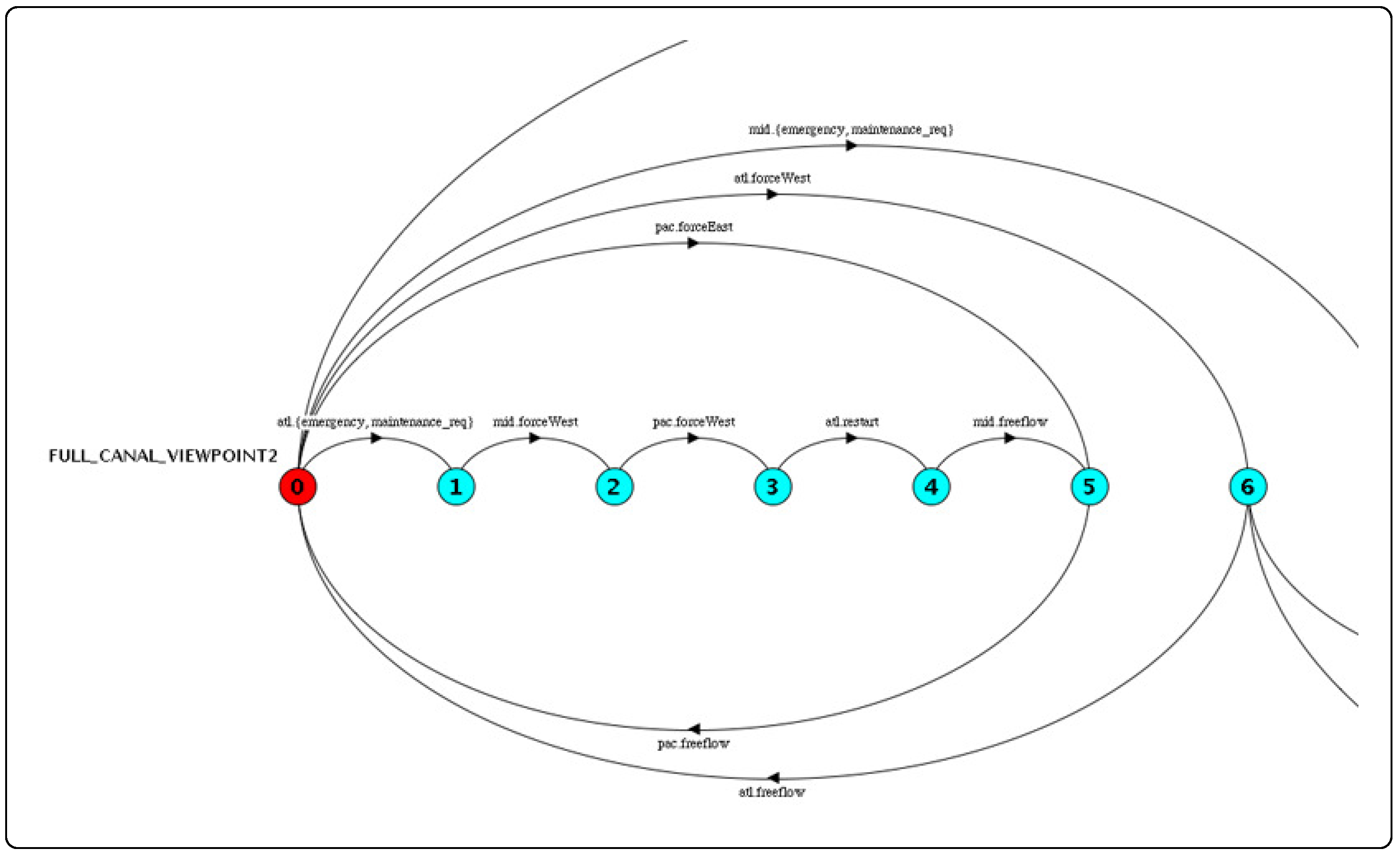
Figure 18 contains a partial view of behavior associated with maintenance/emergency operations and, in particular, shows that a maintenance/emergency event at the Atlantic lockset will be followed by actions directing the Middle and Pacific locksets to process only west-bound traffic.
6. Conclusions and Future Directions
Our work is motivated by the tenet that modern infrastructure systems are a necessary foundation for the transport of goods and services to support global trade and long-term economic growth. The unfortunate reality is that too often failures, delays, and accidents in aging infrastructure systems do little to attract the technical and economic assistance required for modernization. At the same time, remarkable advances in computing and communication technologies over the past few decades have opened doors to the development of physical infrastructure networks tightly connected to cyber (e.g, data, information, and software) for decision making. We believe that modernization efforts will be defined by increased use of automation to: (1) Expand the range of environmental conditions within which systems can safely operate; (2) Support and enhance human performance; and (3) Improve the ability of a system to quickly recover from unexpected disruptions. From a design standpoint, increased use of automation in infrastructure operations introduces new challenges in terms of correctness (assurance and security) of system functionality. From an systems analysis standpoint, compositional approaches to behavior modeling are an essential element to achieving required levels of system agility.
This paper takes a first step toward the development of a compositional approach to distributed system behavior modeling and formal validation of infrastructure operations with finite state automata. Solutions to this problem are complicated by the large number of concurrent processes defining component- and system-level behavior. The difficulty of this problem can be mitigated through hierarchal decomposition of processes, with each level in the hierarchy dealing with a specific set of design concerns. Decomposition does not solve the problem completely, however, because naive approaches to the parallel composition of processes quickly become computationally intractable. To overcome the latter problem, we have proposed a mechanism for process abstraction via viewpoint-action-process traceability. The repeated application of abstraction and process minimization leads to behavior models having size that remains almost constant with respect to problem size (e.g., number of ships traversing the canal system).
There is need for further work in a number of important directions. First, in this study we have investigated the correctness of system functionality with respect to the sequencing of actions. The time needed to complete these actions has been abstracted from consideration. We are currently working on a new behavior model of the canal system represented by networks of timed automata modeled in UPPAAL [
43]. This extension offers the possibility of formally examining the correctness of canal management operations in terms of delays. Although we have talked about the need for sensor-enabled control, the lockset model does not explicitly contain sensor processes. A second generation of process models would place sensors at the center of monitoring activities—to detect the arrival of ships, monitor water levels, and ensure locks are restricted to single use operations. An important benefit of this approach is that ships do not need to be modeled as processes. Instead, they are simply viewed as objects that are directed to pass through the canal system. Finally, we have been creating formalisms [
2,
11] for distributed system behavior modeling of urban systems with ontologies and rules, and exploring ways in which urban networks can interact via message passing mechanisms.


