
Multidimensional-DSP Beamformers Using the ROACH-2 FPGA Platform

1
Department of Electrical and Computer Engineering, University of Akron, Akron, OH 44325, USA
2
Department of Electrical and Computer Engineering, University of Calgary, Calgary, AB T2N 1N4, Canada
*
Author to whom correspondence should be addressed.
Electronics 2017, 6(3), 49; https://doi.org/10.3390/electronics6030049
Submission received: 22 March 2017
/
Revised: 13 June 2017
/
Accepted: 20 June 2017
/
Published: 1 July 2017
(This article belongs to the Special Issue Smart Antennas and MIMO Communications)
Abstract
:Antenna array-based multi-dimensional infinite-impulse response (IIR) digital beamformers are employed in a multitude of radio frequency (RF) applications ranging from electronically-scanned radar, radio telescopes, long-range detection and target tracking. A method to design 3D IIR beam filters using 2D IIR beam filters is described. A cascaded 2D IIR beam filter architecture is proposed based on systolic array architecture as an alternative for an existing radar application. Differential-form transfer function and polyphase structures are employed in the design to gain an increase in the speed of operation to gigahertz range. The feasibility of practical implementation of a 4-phase polyphase 2D IIR beam filter is explored. A digital hardware prototype is designed, implemented and tested using a ROACH-2 Field Programmable Gate Array (FPGA) platform fitted with a Xilinx Virtex-6 SX475T FPGA chip and multi-input analog-to-digital converters (ADC) boards set to a maximum sampling rate of 960 MHz. The article describes a method to build a 3D IIR beamformer using polyphase structures. A comparison of technical specifications of an existing radar application based on phased-array and the proposed 3D IIR beamformer is also explained to illustrate the proposed method to be a better alternative for such applications.
Keywords:
antenna arrays; beamforming; beam filter; multirate; polyphase; FPGA; ROACH-2; multi-dimensional; radar1. Introduction
Applications of antenna array-based electronically steerable directional beamformers can be found in a range of areas such as mobile communications, radar [1,2], microwave sensing, long-range detection and target tracking, cognitive radio and radio telescope arrays [3,4,5]. Ultra-wideband (UWB) beamforming on a uniform linear array (ULA) of broadband antennas [6,7] enables directional-selective enhancement of propagating far-field uniform plane wave signals having a given direction of arrival (DOA). Processing of wideband signals at multi-GHz frequencies in the microwave and mm-wave spectrum require highly efficient signal processing algorithms combined with circuits capable of parallel processing to support massive real-time data throughput.
In the context of digital filter realization, IIR beam filters are low in computational complexity [8] compared to typical interpolating finite-impulse response (FIR) filters that are based on the well-known delay-and-sum approach [9]. Multi-dimensional (MD) IIR digital beam filters can be modeled using the concept of network resonance [10], leading to beam filters that have exciting new applications in real-time digital smart antenna array beamforming. Thus, IIR based MD space-time frequency-planar digital beam filters [11,12] are likely to be efficient in power consumption in comparison with FIR MD beam filters. It has been shown that IIR beam filters have a significantly low multiplier count over FIR beam filters [13].
Recently, it has been shown that the “Reconfigurable open architecture computing hardware-version 2 (ROACH-2)” [14,15] FPGA platform is suitable for digital RF beamformer realizations [16]. The ROACH-2 is an open-source platform for high-performance RF digital signal processing. Ref. [16] shows a recent study on the potential of realizing 2D IIR beam filters in ROACH-2 at a ceiling frequency of 200 MHz. The uniqueness of ROACH-2 is that it provides integration of multi-input ADC cards [17,18] and high-speed networking interfaces. However, ROACH-2 multi-channel ADC cards have restrictions in maximum achievable sampling frequencies with an upper bound of 240 MSamples/s when all 16 inputs are enabled, thus limiting the maximum beamformer operating frequency at 240 MHz. In order to overcome these limitations, the authors in [19] proposed the use of multirate signal processing [20,21,22] to increase the real-time computational throughput at the cost of circuit complexity by parallel processing [23]. By using polyphase structures [21] in the temporal feedback loop in the IIR beam filter, it is possible to achieve an increase in operating frequency by a factor of the number of M polyphases. The authors in [19] describe a multirate 2D IIR RF beamformer realized on ROACH-2 with two polyphases that can operate at a frequency of 480 MHz.
This paper concentrates on an extended design of the multirate wideband beamformer stated earlier that can operate close to 1 GHz and developed further to achieve 3D beamforming for planar antenna arrays. The novelty of this research is that this is the first study of its kind that involves building a 3D IIR beamformer using polyphase structures. The content of this paper is organized as follows: this section provides a review of the MD theoretical concepts related to the underlying research work and polyphase structures. The next section will introduce cascaded beam filter structures for 3D beamforming along with the design methodology. The simulation and results section will provide graphical and quantitative outcomes to elaborate the performance of the proposed beam filter. Lastly, we will discuss the potential for practical realization by comparing this design with an existing real world application and probable future work related to this research.
2. MD Frequency-Planar IIR Beam Filters
2.1. 2D Plane Wave Signals
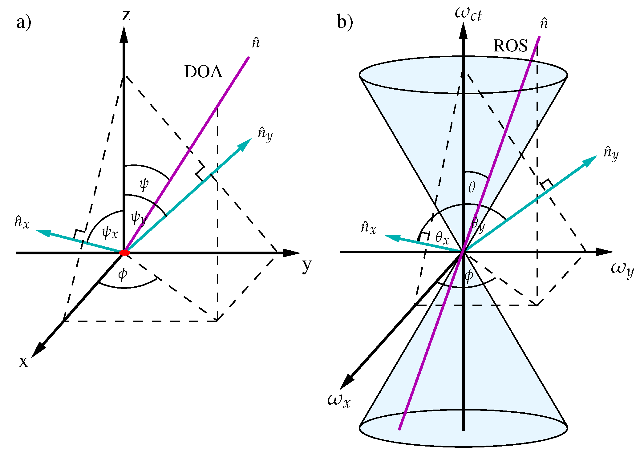
A 2D plane wave received from a DOA on a ULA in the 2D space (x,y) plane can be mathematically represented as follows as shown in Figure 1):
where measured from the broadside direction. The region of support (ROS) in the 2D frequency domain is confined into a line-shaped passband [13,24] oriented at an angle from the -axis passing thorough the origin , where and are spatial and temporal frequencies, respectively in Figure 1b. Here, [25,26].
2.2. Defining 3D Plane Wave Signals from 2D Analogy
The idea of interpreting 3D plane waves [27] using 2D plane wave signals is based on filtering the signal from two orthogonal spatial dimensions. Since, x, y, and dimensions are orthogonal to each other, it is possible to design 3D beamfomers using two 2D beam filters placed in series. Hence, the view of the signal in and are totally different as shown in Figure 2. The ROSs for each plane can be defined as:
in 3D space-time [25,26].
The 3D plane-wave is uniformly sampled by a planar antenna array. The distance between two antenna array elements is given by, , where the highest temporal frequency of the 2D plane wave is and is the speed of light in a vacuum.
2.3. Network Resonant 2D IIR Digital Beam Filters
The differential form transfer function [28] of the first-order 2D IIR beam filter directionally enhancing plane waves received from a DOA is given by [29]:
where the filter coefficients are given by
The selectivity parameter and .
3. Polyphase Differential-Form Transfer-Function
We propose a systolic-array architecture to realize each digital beam filter consisting of a pipelined mesh interconnection of identical parallel processing core modules (PPCMs) [30]. In general, systolic array designs [31] are considered to be low in complexity and have high speed. The multirate design of the PPCM is derived by applying look-ahead (LA) optimization techniques [32]. Polyphase structures are applied on the temporal feedback loop of the transfer function in IIR digital filters. The M-phase polyphase architecture [33] with LA optimization can be written in the form:
where
Here, Equation (8) represents the discrete-domain spatial differential operator. The filter coefficients are given by and for defined in terms of [19]. The polynomial term in the numerator represents the LA optimized terms for pre-defined number of polyphases. Here, note that each polyphase operates at the FPGA fabric rate resulting a combined frame rate of . From Equation (8), it is evident that when the number of polyphases increases, the number of required multipliers and adders to implement a PPCM increases exponentially.
4. Cascaded Beam Filters for 3D Beamformers
By referring to the 3D plane wave theory described earlier, a 3D beamformer can be realized in hardware by cascading two 2D beam filters directionally enhancing signals in and planes [34]. Thus, the transfer function of the 3D beam filter can be represented using 2D beam filters as follows:
The filter co-efficients of and take the form of Equation (5) using the relevant value from Equations (2) and (3).
The intersected region of the two beam filters represents the frequency response of the 3D beam filter as in Figure 3, thus resulting in a beam-shaped passband with the warping effect at higher frequencies.
5. System Architecture
We propose a systolic array-based design because it is considered to be highly efficient for parallel processing of signals for homogeneous networks of tightly coupled data processing units is shown in Figure 4. The systolic array digital computation unit consists of an array of interconnected identical PPCMs within the Virtex-6 SX475T FPGA on the ROACH-2 processing platform. For our scope, we consider an antenna array of 32 elements (). Thus, the ADC front end of the beamformer would consist of 32 ADC chips [17,35]. Each ADC input can sample signals at a rate of 960 MSamples/s at the highest demux setting of 4. However, for our simulations, we feed in the data to the beam filter using ROACH-2 memory blocks (Shared BRAM) for the polyphased inputs using a similar technique as described in [19]. A single HMCAD1520 ADC chip [35] is capable of operating at multiple sampling rates depending on the number of ADC inputs used. The ADC should be clocked at 960 MHz to achieve the highest sampling rate of 960 MSamples/s, while limiting the FPGA design operating frequency to 240 MHz. Here, the ADC produces four time-interleaved samples of the analog signal through the four output channels resulting in four-phase polyphase samples, making it ideal to suit the beam filter requirements. The design of digital realizations was done within a MATLAB environment using a Matlab/Simulink/System Generator/Embedded Development Kit (EDK) (MSSGE) toolflow [36] for Casper ROACH-2.
5.1. PPCM Block
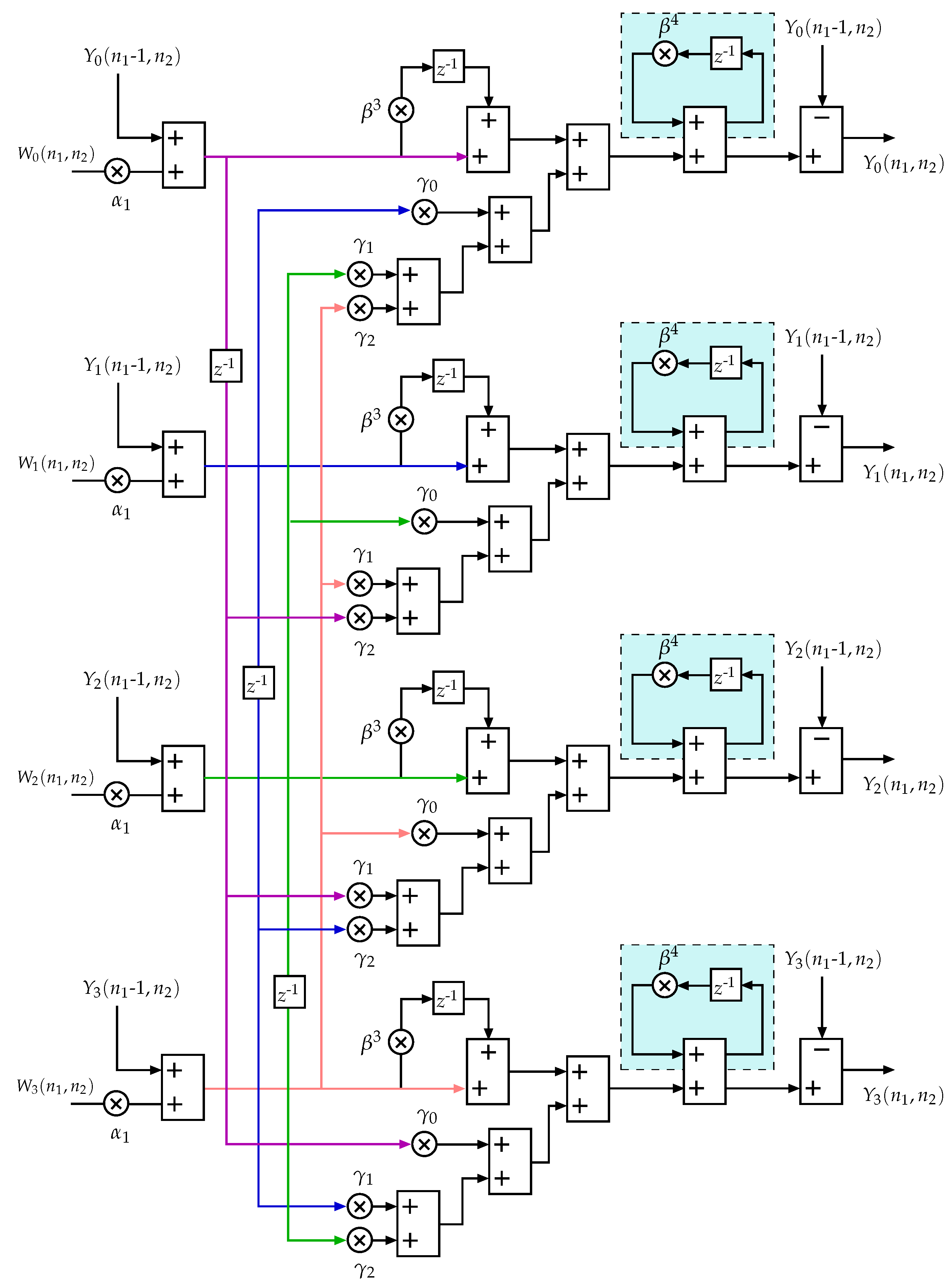
The complex architecture of the four-phase PPCM architecture is shown in Figure 5. The final PPCM module was obtained by applying third-order LA optimization techniques, resulting in a more complex design with lower resource consumption than single polyphase designs. The four-phase PPCM module requires a minimum of 24 multipliers, 28 adder/subtractors, and 11 delay elements. Each block has eight inputs and eight outputs.
6. Simulation and Results
6.1. Filter Response of Four-Phase Polyphase 2D IIR Beam Filter
The frequency domain response of the 4-phase 2D IIR beam filter simulation results is shown in Figure 6. The beamformed output results of the interpolated signal as well as the individual phases were also determined for 16- and 32-bit input vectors. The directional selectivity parameter was assumed to be for all simulations. The filter was tuned to directionally enhance signals arriving at a DOA of . The pipelining latency was set to 16 clock cycles. The filter was set to sample the received signal at a frequency of MHz. The beam filter performance was also determined by feeding in three Gaussian modulated pulses with DOAs , , as shown in Figure 7a. The beam filter successfully filtered out the desired signal with DOA while suppressing the undesired plane-wave signals. The decomposed output in the frequency domain of the filtered signal that has a DOA of is illustrated in Figure 7b,c.
6.2. PPCM Digital Design Complexity
We can obtain a clear insight of the design complexity and the variation in resource consumption from Table 1. We can clearly observe a gradual increase in the chip area for both the direct form and the differential form version. However, the rate of increase in resource consumption in the differential form version design is comparatively less. The number of multiplier and adder/subtractor count has increased by 300% and 280%, respectively, in the four-phase scenario compared with the two-phase 2D IIR beam filter.
6.3. Frequency Response of the 3D IIR Beam Filter
The beam-shaped pass-band (frequency response) obtained for the 3D IIR beam filter using the proposed method is shown in Figure 8 for 32 antenna element arrays. The filter was tuned to a DOA of and in this scenario with a selectivity parameter of .
6.4. Directional Enhancement Properties
Three raised cosine Gaussian modulated signals with three distinct DOA pairs—, and —were fed to the filter to observe the performance of the filter as illustrated in Figure 8b with the desired signal being . The selectivity parameter was assumed to be . The filter successfully filtered out the desired signal as shown in Figure 8c.
6.5. FPGA Implementation
Table 2 shows the evaluation of hardware complexity and real-time performance considered the following metrics: the number of used configurable logic blocks (CLB), flip-flop (FF) count, critical path delay (), and the maximum operating frequency () in MHz.
7. Military Radar Application Based on 3D IIR Beam Filters
The state-of-the-art radar tracking systems used in the military are based on phased-arrays and operate at ≈ 3.5 GHz frequency range [37]. Phased arrays are based on FIR beam filters, which consume more hardware resources in comparison with IIR beamformers. We propose to use an IIR beamformer in place of the phased array to take advantage of smaller chip area and reduced cost. This section details a technical analysis of a 3D radar based on IIR beamformers designed using polyphase structures, cascaded MD IIR beam filters and ROACH-2 hardware platform and compares its features with technical specifications for an advanced military radar system [37]. The key goal is to elaborate on the relevance of this study as a better alternative than the existing designs.
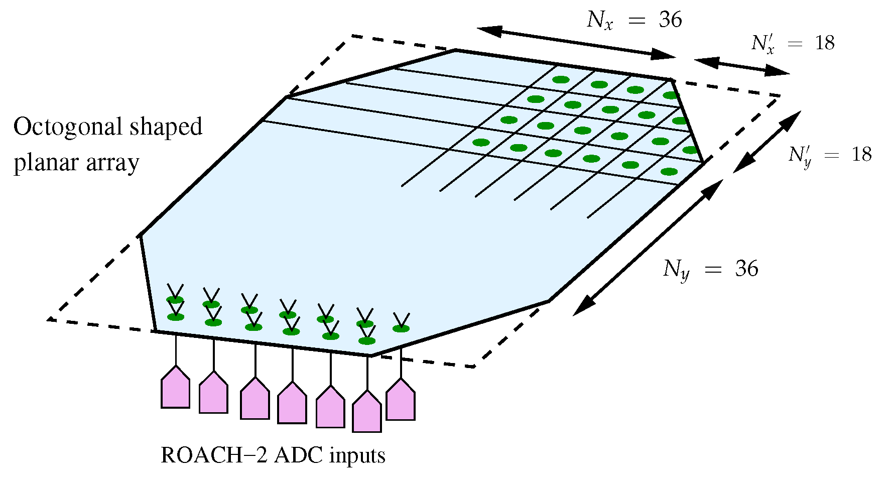
We consider an octagonal-shaped symmetrical planar array with 4572 antenna elements as shown in Figure 9. Hence, the planar array will consist of systolic array based ULAs of different sizes ranging from 36 to 72 antenna elements. The inter antenna spacing and the size of the antennas will vary depending on the operating frequency of the beam filter. By using multirate 2D IIR beam filters (with four polyphases), it is possible to have the FPGA fabric rate reduced by a factor of 4. A beam filter operating at 3.5 GHz requires polyphases to operate at 1.75 GHz ().
For our analysis, we selected three ADC boards that can be interfaced with ROACH-2 to sample RF signals in the GHz range [17,38,39] as stated in Table 3. The overall resource requirement varies depending on the ADC board of interest. We consider ADC16x250-8 RJ45 rev-1 [17], the 16-input ADC board used for realizations described in this research as the main reference. ADC1x5000-8 [38] and KatADC [39] are two-input ADC boards that can sample signals at 2.5 and 1.5 GHz, respectively. All three ADC boards considered here sample the signal with 8-bit quantization levels. KatADC is a popular ADC developed by Texas Instruments Inc. that is widely used in radio telescopes such as the Square Kilometer Array (SKA) [40].
This 3D IIR beamformer is a complex design that requires a large chip area. Both cascaded 2D IIR beamformers require the same number of multipliers and adder/subtractors; they require =) 219,456 multipliers and =) 256,032 adders, respectively. Table 4 illustrates the approximate number of ROACH-2 boards required and the size or the planar array for each ADC board in consideration. The calculation for array size is based on the minimum antenna distance [41,42,43] multiplied by the maximum number of antenna elements per row/column for each ADC in consideration. The area of the planar array is based on the octagonal shape stated above. The required number of ROACH-2 boards is calculated based on the ADC cards required for the two 2D beam filters placed in cascade. The proposed deployment requires a large number of ROACH-2 boards (Table 4). The number of ROACH-2 boards required for second-stage beam filter arrays are governed by the maximum throughput of Small form-factor pluggable (SFP)+ 10 Gigabit Ethernet (GbE) interfaces. Each ROACH-2 can transmit and receive data at a maximum rate of 80 Gbps. At high operating fabric rates, the throughput of produced samples for Kat-7 ADC and ADC1x5000-8 exceeds 80 Gbps. This limits the ability to optimally use ROACH-2 resources resulting in having only one ADC card instead of two per ROACH-2 FPGA boards to ensure that the networking throughout is manageable. Thus, more ROACH-2 boards are required to build the beamformer resulting in increase in cost. It is also important to note that an intermediate subsystem should be placed at the end of each beamformer to perform networking and switching operations as needed. However, using a customized processing board design will ensure efficient use of ADC front ends, FPGA chips and GbE interfaces for a better cost-effective design.
Use of 16-input ADC boards does not suit a practical scenario due to the large area (≈25 m) required to accommodate the antenna array; arrays of this size would be easy targets in warships. Moreover, the achievable maximum operating frequency is limited at ≈2 GHz. However, when the radar is designed using the other two ADC boards, the required area is significantly reduced. ADC1x5000-8 requires only ≈4 m area and can operate at 5 GHz, making it a better match. However, this comes with a trade-off in power consumption and cost for the increased hardware resources (Table 4).
8. Conclusions
This study was focused on a method to build a wideband beamformer operating in the gigahertz range that has practical implications in RF applications. Such plane-wave filters have emerging applications in broadband beamforming using antenna arrays in areas such as radar, microwave imaging and radio astronomy. The differential form IIR beam filters together with multirate structures help to overcome the limitations in operating frequencies in ADCs and FPGA clock rates. We prove the successful realization of a systolic array–based wideband beamformer that can operate at 1 GHz from the 2D IIR multirate digital filter with four-polyphases described. However, during the research, it was also noticed that this improvement comes with an increase in hardware resource consumption and power consumption when compared with non-polyphased designs. The differential form version is efficient in chip area in comparison with the direct form beam filter design. This design can be of use as long as the application can tolerate this excessive resource requirement. The article also highlights the design of a 3D IIR beamformer by cascading two polyphased 2D IIR beamformers. The ROACH-2 hardware platform provides a sophisticated test bed to implement complete end-to-end systems and generate processed signals to do real-time analysis.
One probable application is a 3D radar to detect and track targets. From the analysis, we can clearly see that the hardware chip area and the computational complexity is on the high side for a planar array with a large number of antenna elements. Thus, bulky and heavy power sources are needed to meet the power requirements of these designs. The limitations in maximum fabric rate and 10 GbE networking interfaces in a ROACH-2 hardware platform affect the hardware resource consumption. Another key influencing factor is the type of ADCs used and their maximum sampling rate. Most of the ADC chips are limited to no more than a few GSamples/s with the current technology. It is possible to build beamformers with better performance if ADC boards are able to sample in the 10 GSamples/s range with more ADC inputs and FPGAs that can support required fabric rates. However, since IIR beamformers are more computationally efficient than FIR beamformers in general, we believe that this method would be a suitable alternative for a sensitive target tracking and detection application [37].
In the future, it is expected to expand the study to include methods to address the disadvantages in polyphase structure designs of increased complexity and resource consumption using more efficient algorithms. A further exploration of methods to improve the critical path delay may yield better performance in terms of speed-power-latency-area.
Acknowledgments
Arjuna Madanayake thanks the Xilinx University Program (XUP) for the donation of two Xilinx SX475T FPGAs that are installed in ROACH-2 FPGA platforms. This work is supported in part by the US National Science Foundation (NSF) ECCS Award Number 1408361 “Collaborative Research: Electronically-Scanned Wideband Digital Aperture Antenna Arrays using Multi-Dimensional Space-Time Circuit-Network Resonance: Theory and Hardware”, NSF “EARS: Collaborative Research: Enhancing Spectral Access via Directional Spectrum Sensing Employing 3D Cone Filterbanks: Interdisciplinary Algorithms and Prototypes”, Award Number 1247940, and the Office Of Naval Research (ONR) Award Number N000141410197.
Author Contributions
Vishwa Seneviratne research on designing the digital design for the MD polyphase digital beam filter, performed the simulations and analyzed results. Arjuna Madanayake and Len. T. Briton supervised the research and co-authored the paper.
Conflicts of Interest
The authors declare no conflict of interest.
References
- Kant, G.W.; Patel, P.D.; Wijnholds, S.J.; Ruiter, M.; van der Wal, E. EMBRACE: A Multi-Beam 20,000-Element Radio Astronomical Phased Array Antenna Demonstrator. IEEE Trans. Antennas Propag. 2011, 59, 1990–2003. [Google Scholar] [CrossRef]
- Krishnaswamy, H.; Hashemi, H. A 4-channel 4-beam 24-to-26 GHz spatio-temporal RAKE radar transceiver in 90nm CMOS for vehicular radar applications. In Proceedings of the 2010 IEEE International Solid-State Circuits Conference Digest of Technical Papers, San Francisco, CA, USA, 7–11 February 2010; pp. 214–215. [Google Scholar]
- Madanayake, A.; Wijenayake, C.; Dansereau, D.G.; Gunaratne, T.K.; Bruton, L.T.; Williams, S.B. Multidimensional (MD) circuits and systems for emerging applications including cognitive radio, radio astronomy, robot vision and imaging. IEEE Circuits Syst. Mag. 2013, 13, 10–43. [Google Scholar] [CrossRef]
- Bosse, S.; Barth, S.; Torchinsky, S.; Da Silva, B. Beamformer ASIC in UHF-L band for the square kilometer array international project. In Proceedings of the IEEE European Microwave Integrated Circuits Conference (EuMIC), Paris, France, 27–28 September 2010; pp. 106–109. [Google Scholar]
- Elmer, M.; Jeffs, B.D.; Warnick, K.F.; Fisher, J.R.; Norrod, R.D. Beamformer Design Methods for Radio Astronomical Phased Array Feeds. IEEE Trans. Antennas Propag. 2012, 60, 903–914. [Google Scholar] [CrossRef]
- Li, T.; Rao, Y.; Niu, Z. Analysis and Design of UWB Vivaldi Antenna. In Proceedings of the International Symposium on Microwave, Antenna, Propagation and EMC Technologies for Wireless Communications, Hangzhou, China, 16–17 August 2007; pp. 579–581. [Google Scholar]
- Madanayake, A.; Wijenayake, C.; Belostotski, L.; Bruton, L.T. An overview of multi-dimensional RF signal processing for array receivers. In Proceedings of the Moratuwa Engineering Research Conference (MERCon), Moratuwa, Sri Lanka, 7–8 April 2015; pp. 255–259. [Google Scholar]
- Wijenayake, C.; Madanayake, A.; Bruton, L.T. Broadband Multiple Cone-Beam 3-D IIR Digital Filters Applied to Planar Dense Aperture Arrays. IEEE Trans. Antennas Propag. 2012, 60, 5136–5146. [Google Scholar] [CrossRef]
- Ghavami, M.; Kohno, R. Frequency selective broadband beamforming using 2D digital filters. In Proceedings of the IEEE 51st Vehicular Technology Conference Proceedings, Tokyo, Japan, 15–18 May 2000; Volume 3, pp. 2522–2526. [Google Scholar]
- Zhang, Y.; Bruton, L.T. Applications of 3D LCR networks in the design of 3D recursive filters for processing image sequences. IEEE Trans. Circuits Syst. Video Technol. 1994, 4, 369–382. [Google Scholar] [CrossRef]
- Agathoklis, P.; Bruton, L.T. Practical-BIBO stability of N-dimensional discrete systems. IEE Proc. G Electron. Circuits Syst. IET 1983, 130, 236–242. [Google Scholar] [CrossRef]
- Bruton, L.; Bartley, N. Three-dimensional image processing using the concept of network resonance. IEEE Trans. Circuits Syst. 1985, 32, 664–672. [Google Scholar] [CrossRef]
- Madanayake, A.; Hum, S.V.; Bruton, L.T. A Systolic Array 2-D IIR Broadband RF Beamformer. IEEE Trans. Circuits Syst. II Express Briefs 2008, 55, 1244–1248. [Google Scholar] [CrossRef]
- CASPER Group. Berkeley Wireless Research Center. The University of California, Berkeley. Available online: https://casper.berkeley.edu (accessed on 1 July 2017).
- Casper ROACH-2 Revision 2. CASPER Group Berkeley Wireless Research Center. The University of California, Berkeley. Available online: https://casper.berkeley.edu/wiki/ROACH2 (accessed on 1 July 2017).
- Seneviratne, V.; Madanayake, A.; Udayanga, N. Wideband 32-element 200 MHz 2-D IIR beam filters using ROACH-2 Virtex-6 sx475t FPGA. In Proceedings of the IEEE 9th International Workshop on Multidimensional (nD) Systems (nDS), Vila Real, Portugal, 7–9 September 2015; pp. 1–5. [Google Scholar]
- ADC16x250-8 RJ45 rev 1. Hittite Microwave Corporation. Available online: https://casper.berkeley.edu/wiki/ADC16x250-8 (accessed on 1 July 2017).
- ADC4x250-8. Hittite Microwave Corporation. Available online: https://casper.berkeley.edu/wiki/ADC4x250-8 (accessed on 1 July 2017).
- Seneviratne, V.; Madanayake, A.; Bruton, L.T. A 480MHz ROACH-2 FPGA realization of 2-phase 2D IIR beam filters for digital RF apertures. In Proceedings of the 2016 Moratuwa Engineering Research Conference (MERCon), Moratuwa, Sri Lanka, 5–6 April 2016; pp. 120–125. [Google Scholar]
- Vaidyanathan, P.P. Multirate digital filters, filter banks, polyphase networks, and applications: A tutorial. Proc. IEEE 1990, 78, 56–93. [Google Scholar] [CrossRef]
- Franca, J.; Petraglia, A.; Mitra, S.K. Multirate analog-digital systems for signal processing and conversion. Proc. IEEE 1997, 85, 242–262. [Google Scholar] [CrossRef]
- Vaidyanathan, P.P. Multirate Systems and Filter Banks; Pearson Education India: Delhi, India, 1993. [Google Scholar]
- Madanayake, A.; Gunaratne, T.K.; Bruton, L.T. Massively parallel systolic-array architectures for 2-D IIR polyphase space-time plane-wave beam digital filters. Int. J. Circuit Theory Appl. 2012, 40, 455–475. [Google Scholar] [CrossRef]
- Udayanga, N.; Madanayake, A.; Wijenayake, C.; Acosta, R. Applebaum adaptive array apertures with 2-D IIR space-time circuit-network resonant pre-filters. In Proceedings of the IEEE Radar Conference (RadarCon), Arlington, VA, USA, 10–15 May 2015; pp. 0611–0615. [Google Scholar]
- Roderick, J.; Krishnaswamy, H.; Newton, K.; Hashemi, H. Silicon-Based Ultra-Wideband Beam-Forming. IEEE J. Solid-State Circuits 2006, 41, 1726–1739. [Google Scholar] [CrossRef]
- Khademi, L. Reducing the Computational Complexity of FIR 2-D Fan and 3-D Cone Filters. Master’s Thesis, Department of Electrical and Computer Engineering University of Calgary, Calgary, AB, Canada, 2004. [Google Scholar]
- Madanayake, A.; Bruton, L.T. Radio-Frequency (RF) Beamforming Using Systolic FPGA-Based Two Dimensional (2D) IIR Space-Time Filters; INTECH Open Access Publisher: Rijeka, Croatia, 2010. [Google Scholar]
- Bruton, L.T.; Madanayake, A.; Wijenayake, C.; Maini, M. Continuous-Time Analog Two-Dimensional IIR Beam Filters. IEEE Trans. Circuits Syst. II Express Briefs 2012, 59, 419–423. [Google Scholar] [CrossRef]
- Madanayake, A.; Bruton, L.T. A Speed-Optimized Systolic Array Processor Architecture for Spatio-Temporal 2-D IIR Broadband Beam Filters. IEEE Trans. Circuits and Syst. I Regul. Pap. 2008, 55, 1953–1966. [Google Scholar] [CrossRef]
- Madanayake, A.; Bruton, L.T. Low-complexity distributed parallel processor for 2-D IIR broadband beam plane-wave filters. Can. J. Electr. Comput. Eng. 2007, 32, 123–131. [Google Scholar] [CrossRef]
- Madanayake, A.; Bruton, L.T. FPGA Prototyping of Spatio-temporal 2-D IIR Broadband Beam Plane-wave Filters. In Proceedings of the IEEE Asia Pacific Conference on Circuits and Systems, Singapore, 4–7 December 2006; pp. 542–545. [Google Scholar]
- Parhi, K.; Messerschmitt, D. Look-ahead computation: Improving iteration bound in linear recursions. In Proceedings of the IEEE International Conference on Acoustics, Speech, and Signal Processing, Dallas, TX, USA, 6–9 April 1987; Volume 12, pp. 1855–1858. [Google Scholar]
- Madanayake, A.; Gunaratne, T.K.; Bruton, L.T. Reducing the Multiplier-Complexity of Massively Parallel Polyphase 2-D IIR Broadband Beam Filters. Circuits Syst. Signal Proc. 2012, 31, 1229–1243. [Google Scholar] [CrossRef]
- Bruton, L.T. Three-dimensional cone filter banks. IEEE Trans. Circuits Syst. I Fundam. Theory Appl. 2003, 50, 208–216. [Google Scholar] [CrossRef]
- HMCAD1520 ADC Chip Datasheet. Hittite Microwave Corporation. Available online: http://www.analog.com/media/en/technical-documentation/data-sheets/hmcad1520.pdf (accessed on 1 July 2017).
- MSSGE Toolflow Setup. Available online: https://casper.berkeley.edu/wiki/MSSGE_Toolflow_Setup (accessed on 1 July 2017).
- Dranidis, D.V. Airborne Stealth in a Nutshell-part I. the Magazine of the Computer Harpoon Community. 2012. Available online: http://www.harpoonhq.com/waypoint/ (accessed on 1 February 2009).
- ADC1x5000-8. ev2 Semiconductors. Available online: https://casper.berkeley.edu/wiki/ADC1x5000-8 (accessed on 1 July 2017).
- KatADC (ADC08D1520). Texas Instruments Inc. Available online: https://casper.berkeley.edu/wiki/KatADC (accessed on 1 July 2017).
- SKA Aperture Arrays. SKA Organization. Available online: https://www.skatelescope.org/aperture-arrays/ (accessed on 1 July 2017).
- Hansen, R.C. Phased Array Antennas; John Wiley & Sons: Hoboken, NJ, USA, 2009; Volume 213. [Google Scholar]
- Schelkunoff, S.A. A mathematical theory of linear arrays. Bell Labs Tech. J. 1943, 22, 80–107. [Google Scholar] [CrossRef]
- Balanis, C.A. Antenna Theory: Analysis and Design; John Wiley & Sons: Hoboken, NJ, USA, 2016. [Google Scholar]
Figure 1.
Plane wave received at a uniform linear array of antennas with spacing in (a) 2D space (x, y) domain and (b) 2D space-time (x, ct) domain.
Figure 1.
Plane wave received at a uniform linear array of antennas with spacing in (a) 2D space (x, y) domain and (b) 2D space-time (x, ct) domain.
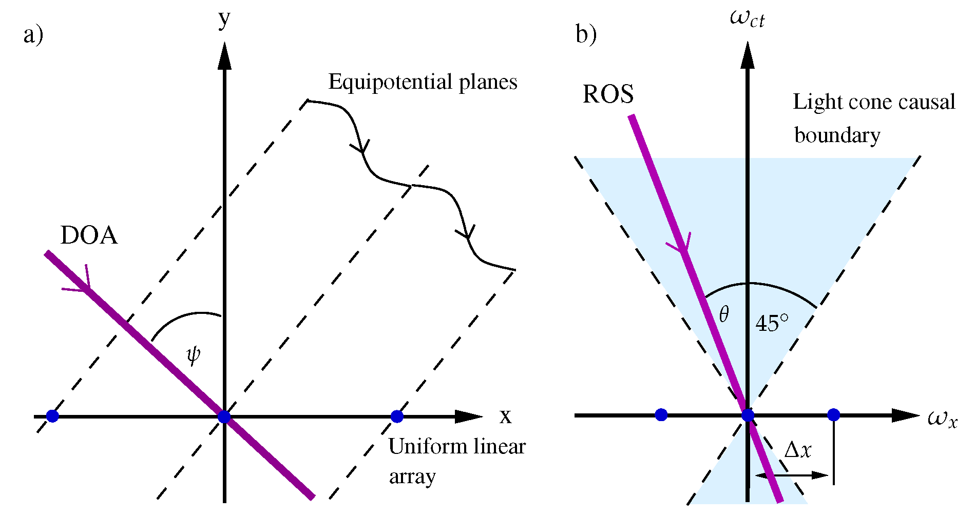
Figure 2.
The graphical analogy of an incident plane wave. (a) incident plane wave in 3D space domain used to derive the cascaded 2D beam filters and (b) 3D space-time domain.
Figure 2.
The graphical analogy of an incident plane wave. (a) incident plane wave in 3D space domain used to derive the cascaded 2D beam filters and (b) 3D space-time domain.

Figure 3.
Frequency response of cascading of two 2D IIR beam filters to obtain the 3D IIR beam filter. (a) frequency response of and (b) responses of two filters before intersecting the beam filters.
Figure 3.
Frequency response of cascading of two 2D IIR beam filters to obtain the 3D IIR beam filter. (a) frequency response of and (b) responses of two filters before intersecting the beam filters.
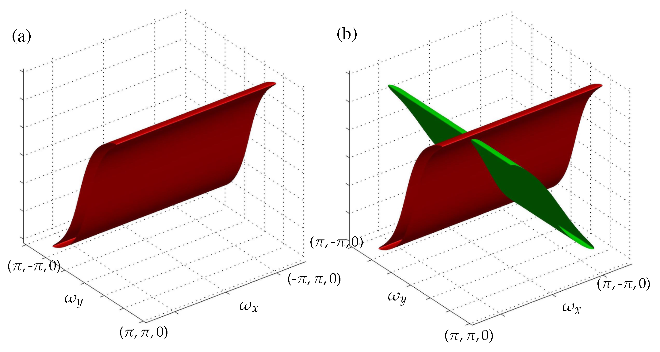
Figure 4.
Proposed systolic array architecture of the four phase 2D IIR beam filter with RF front-ends in a ROACH-2 FPGA platform.
Figure 4.
Proposed systolic array architecture of the four phase 2D IIR beam filter with RF front-ends in a ROACH-2 FPGA platform.
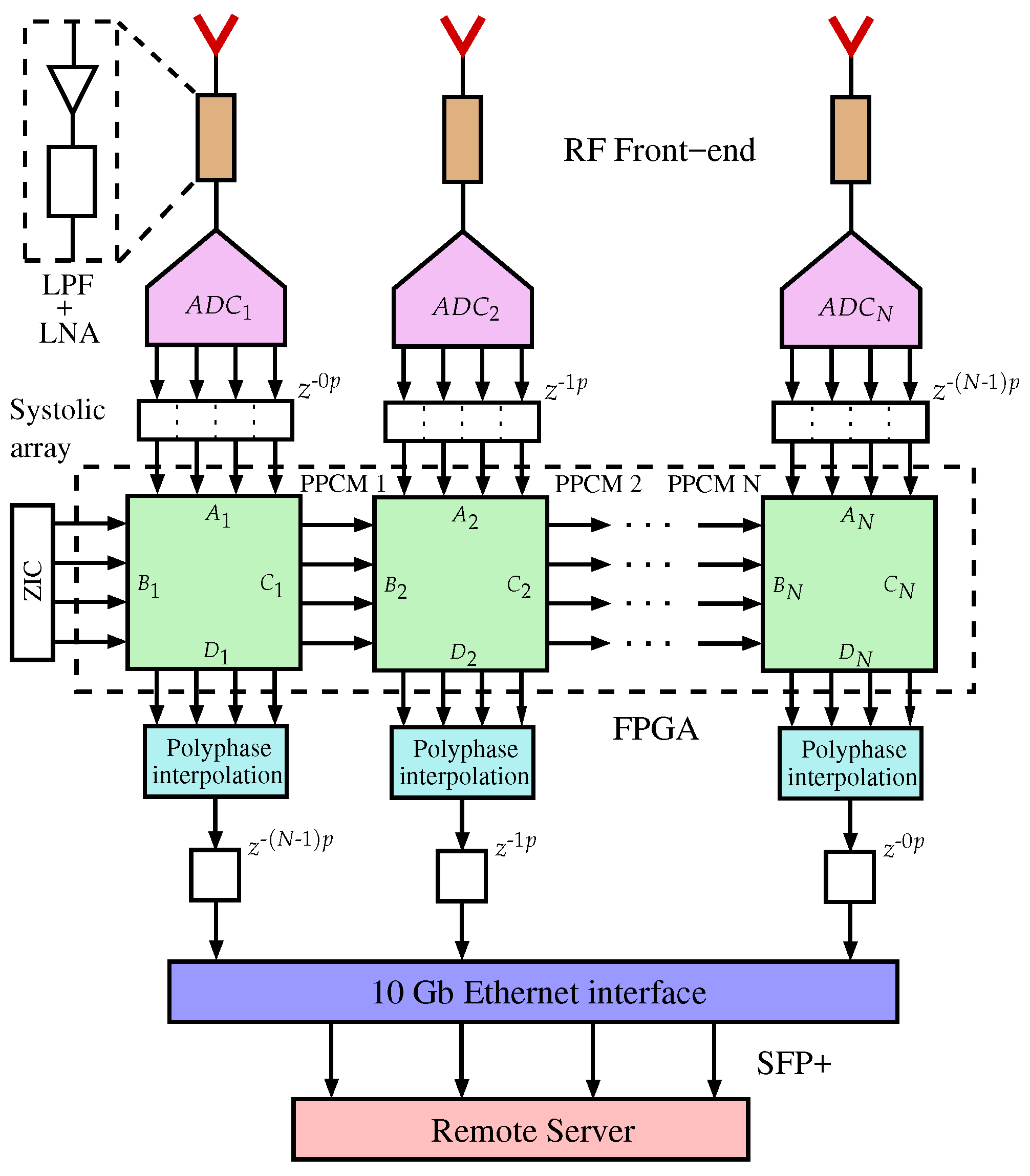
Figure 5.
The time-interleaved polyphase PPCM block of the systolic array based four-phase 2D IIR beam filter.
Figure 5.
The time-interleaved polyphase PPCM block of the systolic array based four-phase 2D IIR beam filter.

Figure 6.
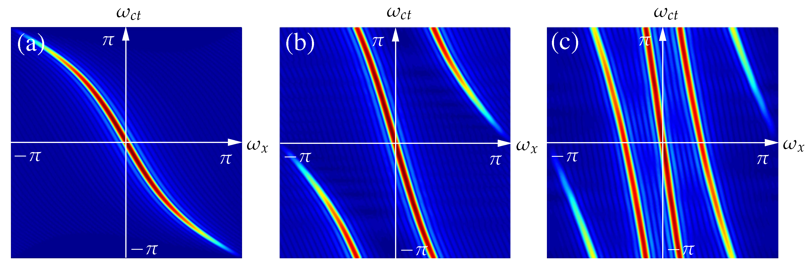
Frequency response of four-phase 2D IIR beam filter tuned to enhance RF signals arriving at a DOA of . (a) response after interpolating the beamformed output of four phases; decomposed polyphase response of (b) two phases illustrating the temporal domain aliasing effect and (c) frequency response of a single phase.
Figure 6.
Frequency response of four-phase 2D IIR beam filter tuned to enhance RF signals arriving at a DOA of . (a) response after interpolating the beamformed output of four phases; decomposed polyphase response of (b) two phases illustrating the temporal domain aliasing effect and (c) frequency response of a single phase.

Figure 7.
Directional enhancement simulation of the four-phase polyphased 2D IIR beam filter using three Gaussian modulated pulses in frequency domain. (a) wideband input signals with DOAs (); (b) interpolated output signal with directional enhancement and (c) decomposed output of one phase with a temporal aliasing effect.
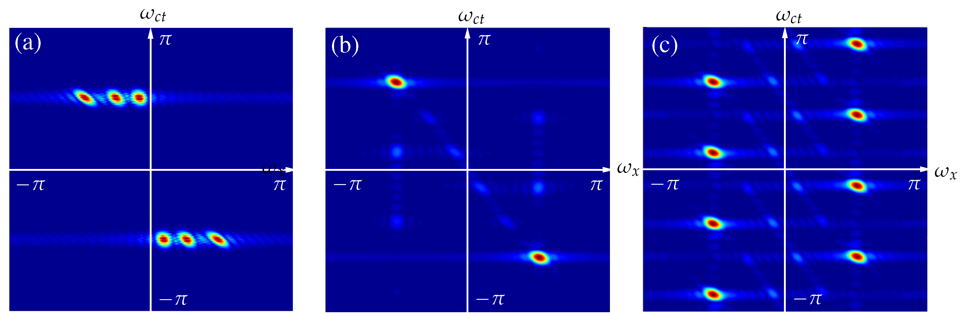
Figure 8.
(a) Frequency response of the 3D IIR beam filter in 3D space-time domain and directional enhancement of plane wave signals using the 3D IIR beam filter; (b) input signal and (c) filtered signal.
Figure 8.
(a) Frequency response of the 3D IIR beam filter in 3D space-time domain and directional enhancement of plane wave signals using the 3D IIR beam filter; (b) input signal and (c) filtered signal.
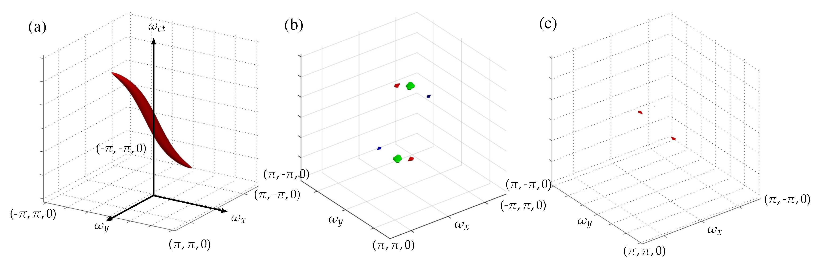
Figure 9.
Proposed octogonal shaped 2D planar antenna array front end of the 3D radar.

Table 1.
Computational complexity of the proposed low-complexity architectures with LA optimization [33] (DRF = Direct form, DFF = Differential form).
Table 1.
Computational complexity of the proposed low-complexity architectures with LA optimization [33] (DRF = Direct form, DFF = Differential form).
| M-Phases | Multipliers (DRF) | Multipliers (DFF) | Relative Reduction | Frame Rate |
|---|---|---|---|---|
| 1 | 3 | 2 | 33% | |
| 2 | 10 | 8 | 20% | |
| 3 | 21 | 15 | 28.6% | |
| 4 | 36 | 24 | 33.3% |
Table 2.
Comparison of FPGA resource consumption for a 32-element differential form polyphased 2D IIR beam filter at 16-bit and 32-bit inputs. (FF = Flip-flop, LUT = Look-Up Table)
Table 2.
Comparison of FPGA resource consumption for a 32-element differential form polyphased 2D IIR beam filter at 16-bit and 32-bit inputs. (FF = Flip-flop, LUT = Look-Up Table)
| Resources | 16-Bits | 32-Bits |
|---|---|---|
| Slice registers | 13,957 | 28,167 |
| Slice LUTs | 30,132 | 69,220 |
| Occupied slices | 9586 | 21,565 |
| LUT-FF pairs | 9089 | 11,005 |
| () | 1.137 | 1.169 |
| Max. frequency () | 879.51 | 855.43 |
Table 3.
Achievable operating speeds of the proposed 3D radar at different ADC sampling rates.
| ADC Board | ADC Inputs | Polyphase Freq., (GHz) | Sampling Freq., (GHz) | Operating Freq., (GHz) | Antenna Space, (mm) |
|---|---|---|---|---|---|
| ADC16x250-8 | 4 | 0.96 | 3.84 | 1.98 | 75.76 |
| Kat-7 ADC | 2 | 1.5 | 6 | 3.00 | 50 |
| ADC1x5000-8 | 2 | 2.5 | 10 | 5.00 | 30 |
Table 4.
Hardware resource consumption, complexity and planar array sizes at different ADC sampling rates.
Table 4.
Hardware resource consumption, complexity and planar array sizes at different ADC sampling rates.
| ADC Board | Total No. of ROACH-2 Boards | Array Size (m) |
|---|---|---|
| ADC16x250-8 | 1032 | |
| Kat-7 ADC | 1829 | |
| ADC1x5000-8 | 2286 |
© 2017 by the authors. Licensee MDPI, Basel, Switzerland. This article is an open access article distributed under the terms and conditions of the Creative Commons Attribution (CC BY) license (http://creativecommons.org/licenses/by/4.0/).
Share and Cite
MDPI and ACS Style
Seneviratne, V.; Madanayake, A.; Bruton, L.T. Multidimensional-DSP Beamformers Using the ROACH-2 FPGA Platform. Electronics 2017, 6, 49. https://doi.org/10.3390/electronics6030049
AMA Style
Seneviratne V, Madanayake A, Bruton LT. Multidimensional-DSP Beamformers Using the ROACH-2 FPGA Platform. Electronics. 2017; 6(3):49. https://doi.org/10.3390/electronics6030049
Chicago/Turabian StyleSeneviratne, Vishwa, Arjuna Madanayake, and Len T. Bruton. 2017. "Multidimensional-DSP Beamformers Using the ROACH-2 FPGA Platform" Electronics 6, no. 3: 49. https://doi.org/10.3390/electronics6030049
Note that from the first issue of 2016, this journal uses article numbers instead of page numbers. See further details here.