Performance of Differential-Phase OFDM Systems over Selective Multipath Fading Channels


Department of Engineering and Physics, University of Central Oklahoma, Edmond, OK 73034, USA
Electronics 2017, 6(3), 66; https://doi.org/10.3390/electronics6030066
Submission received: 10 August 2017
/
Revised: 23 August 2017
/
Accepted: 1 September 2017
/
Published: 5 September 2017
Abstract
:This paper investigates the performance of differential-phase Orthogonal Frequency Division Multiplexing (OFDM) over frequency-selective multipath Nakagami-m radio fading channels. A closed form for the average signal to noise/interference ratio in the presence of the selective multipath fading channel and additive white Gaussian noise (AWGN) is derived. The results reveal that the system performance is impacted by the interference between the adjacent OFDM frames in two successive signaling intervals which is called Inter-Symbol-Interference (ISI). In addition, the system will possibly be distorted when the orthogonality between the adjacent subcarriers is ceased, creating Inter-Channel-Interference (ICI). This paper also studies the bit-error-rate (BER) performance of the differential-phase OFDM system over the Nakagami-m channel in the presence of AWGN, ISI, and ICI under different conditions and parameters. Moreover, the effect of adding the guard period and the number of subchannels on the probability of error is analyzed. The IEEE 802.11a standard parameters with 64 subcarriers and a decaying exponential power delay profile with root-mean-square value of 129 ns are used in this study. The system performance is also simulated at different guard intervals, number of OFDM subcarriers, Nakagami severity parameter values, and different numbers of possible differential phases.
1. Introduction
Orthogonal Frequency Division Multiplexing (OFDM) is a multicarrier digital technology that has been continuously developed over the past five decades due to the high demand for robust digital broadcasting over wireless mobile channels. OFDM offers many advantages over conventional single carrier systems such as robustness against multipath delay spread and frequency-selective fading channels at a low receiver implementation cost [1]. In conventional single carrier (SC) modulation techniques, all symbols are modulated and transmitted over a single frequency carrier. A symbol pulse consisting of M-bits has duration of , where is the bit duration. The transmission bit rate is defined as (bits/second). When the transmitted signal propagates over a terrestrial multipath broadcasting channel, the received signal may experience a delay over the different multipath components. Let the p-th path have a delay of and the longest path has a delay of . The received signal from the longest path may experience an Inter-Symbol-Interference (ISI) and interfere with the previous bits from the shortest path [2]. For example, if a single quadrature-modulated carrier is used with a 20 MHz IEEE 802.11a standard characterized by Mbps, the received bit from the longest path, with s, will interfere with the previous bits [3]. The increase in the bit transmission rate will increase the effect of ISI. In order to remove the interference and extract the original information from the received signal, complex equalization techniques are necessary. Multi carrier (MC) systems with N carriers split the original data stream into N parallel substreams [4]. Each substream is modulated and transmitted through a different single carrier and has a lower bit rate of . However, the entire MC system has a bit transmission rate of . Since these symbols are modulated and transmitted in a multiplexed parallel fashion, the system is called a parallel transmission system. Accordingly, the received bit from the longest path will interfere with the previous = bits. MC systems have proven to be more immune to ISI when compared to SC systems at the same transmission rate [5,6]. This is because MC systems have multi-subchannels, N, with relatively smaller bandwidth per subchannel. Using the example of the IEEE 802.11a system above shows that the ISI can be reduced significantly when subcarriers are employed [7,8]. This will result in = ; that is, the bit received from the longest path will interfere only with the previous bit [9]. In multi carrier systems, the entire available channel bandwidth W is divided into N parallel simultaneous subchannels, each with a bandwidth of . To better utilize the entire channel bandwidth, high spectral efficiency is achieved by allowing overlap between the subchannels. Through the overlapping strategy, signals can be separated at the receiver side if the subchannels’ center frequencies are chosen to be orthogonal. Two frequencies and are considered to be orthogonal if they satisfy the following condition
Therefore, orthogonality can be achieved by choosing the n-th subchannel passband center frequency as for , where , is the smallest center frequency among the N orthogonal frequencies, and is the OFDM frame duration. The frame is a multi-tone block in which all modulated symbols are OFDM encoded. To decrease or eliminate the overlap between the adjacent frames, a guard period, which could be a cyclic prefix or zero padding, i.e., a period of silence with no transmission, with a duration of , can be added between successive frames. This will extend the actual frame duration to . When possible, should be chosen to be greater than the maximum delay in the multipath fading channels. The ratio of the useful frame duration to the total frame duration represents the efficiency in the transmitted power: . Another advantage of increasing the number of orthogonal carriers is to make the subchannel bandwidth small compared to the coherence bandwidth of the channel in the frequency-selective channels, i.e., [4]. Such a condition will enable transmitted symbols to experience almost flat fading (frequency non-selective) which will significantly decrease the complexity of the receiver and allow for a simple equalization process. In a previous effort, the author et al. have studied the performance of enhanced cooperative coding for OFDM systems in frequency flat channels. However, this paper studies uncoded OFDM systems in frequency-selective channels with potential future expansion to this work to include cooperative coding for OFDM systems [10].
In this paper, differential-phase modulation has been chosen to study the performance of OFDM over frequency-selective multipath fading channels. The reason for choosing the differential-phase scheme rather than the coherent-phase scheme is that the differential-phase technique does not require channel estimation or equalization. Channel estimation mandates transmitting pilot symbols which will significantly increase the complexity of the receiver. The price paid by the differential scheme is the requirement of a higher signal-to-noise ratio (SNR) to achieve the same probability of error as for coherent-phase detection. On the other hand, differential-phase modulation can be coherently demodulated and differentially decoded. This method is called quasi-coherent detection which can improve the performance of the system given the same level of SNR [11,12]. The authors in [11] have concluded that transmitting the pilot symbol in coherent-phase OFDM schemes will cause additional loss of around 1.5 dB which justifies the use of differential-phase modulation.
Even with the precautions taken when designing the OFDM system, interference problems are likely to occur but with less severity when compared to single carrier systems. However, interference problems will degrade the performance of the system, and the system will require more procedures to be employed at the receiver side. Due to the nature of fading channels, the orthogonality between subcarriers may cease, causing a specific type of interference known as the Inter-Channel-Interference (ICI). The guard period between the frames is designed to prevent or reduce interference between adjacent OFDM frames. The next section presents the performance of OFDM-encoded differential phase shift keying signals in the presence of multipath frequency-selective Nakagami-m channels. In particular, there will be a focus on the degradation of the system performance in the presence of ISI, ICI, and additive Gaussian noise.
2. Channel Specifications
In a typical terrestrial wireless channel, the transmitted signal propagates over multipath channels which can be modeled as a time-varying random process. The impulse response of the multipath channel, , can be expressed as
where and are the p-th multipath component impulse response and time delay, respectively, is a variable time delay, and P represents the total number of paths in the multipath environment. The phase term represents the total phase shift encountered in the channel due to free space propagation. Practically, the number of the multipath (scatters) is considered to be large enough to represent the channel impulse response, , as a zero-mean complex-valued Normal random process, according to the Central Limit Theorem. Over a small-scale time, the channel impulse can be modeled as a wide-sense-stationary uncorrelated scattering (WSS-UCS) process. Therefore, the correlation function is given by
Over a short distance interval, the delay is relatively independent of the time and it is a uniformly distributed random variable in the range of ]. is the maximum excess delay of the channel given by and is called the bin time delay width given by [13]. The power delay profile, , which represents the signal intensity received over a multipath channel, is obtained as the spatial average of the complex baseband channel impulse response as , such as
where represents the power delay profile of the channel. In OFDM systems, the symbol duration, , is very small when compared with the channel coherence time (). This case is called slow fading in which the envelope, , remains almost constant over a period of several data symbols; thus, and will be treated as a random variable with Nakagami-m probability density function (pdf). Nakagami-m best fit in land mobile to model dense scatters which results in delay times that are relatively close to each other [14,15]. The pdf of the random variable can be given by
where is the gamma function. Nakagami-m distribution represents a general model that can fit the practical measurements of the envelope of the channel impulse response which has a mean square of . The parameter m is called the severity parameter and it measures how much the envelope suffers from fading. In this case, less fading severity is associated with larger values of the fading parameter m. A special case is when , which represents the one-sided Gaussian fading that suffers from more severe fading than the case of , which represents the Rayleigh fading. As m approaches infinity, the channel statistics correspond to nonfading conditions. Other fading distributions that may be approximated from the Nakagami-m pdf are the Rician and log-normal fading distributions under certain conditions. The instantaneous signal-to-noise ratio per symbol, , in terms of can be defined as [16]
where is the energy per symbol, is the one-sided noise energy. The pdf of the random variable can be obtained by the transformation of random variables between and as
3. Problem Statement
3.1. The Transmitted OFDM Signal
The baseband transmitted OFDM signal can be expressed as
where is the rectangular frame pulse waveform defined by
Other types of frame pulse waveforms could be used, such as the Nyquist shape window and the raised cosine window [17,18].
In the differential-phase OFDM scheme similar to the one shown in Figure 1, the modulated symbol is an M-ary DPSK modulated signal carried by the n-th subcarrier and transmitted over the i-th OFDM signaling interval. The modulated symbol can be expressed as [16]
where is the energy per symbol, and is the transmitted phase in the interval from the th OFDM frame. is given by modulo where is one of the M possible differential phases chosen from the set and is the transmitted phase in the interval from the th OFDM frame
3.2. The Received OFDM Signal over Multipath Fading Channels
The transmitted signal, , will experience a delay, a multipath fading propagation while passing through an AWGN channel. Therefore, the received signal, , can be expressed as
where represents the complex-valued AWGN process. Substituting (10) and (2) in (13), the received signal can be written as
The analog-to-digital converter in the OFDM block diagram takes a sample from the received baseband signal every seconds at a sampling rate of . Let the delay in the received signal be and the guard period is . Recall that , , and . Therefore, the discretized received signal is , and it is given by
where , , and are the discrete channel model, the discrete version of the AWGN, and the discrete rectangular window, respectively, and
In slow fading channels, (where ). The GP in the received frame is removed by eliminating the leading samples from the clock. The FFT of has a size of N. The output of the k-th branch of the FFT processor is
Substituting (15) into (17) results in
where is the FFT-processed version of the AWGN. The output of the FFT processor from the k-th branch from the i-th OFDM frame is
where
Since FFT is a linear process, the FFT-processed AWGN in (20) has the same distribution with zero mean as
and variance
where is the AWGN one-sided power spectral density . The OFDM signal is received from the P multipath components with propagation delay where . Some of the propagation delays are less than the guard period, say components, and the rest have propagation delays greater than the guard period. The received signals from the paths have delays of and will not suffer from ISI and ICI, as shown in Figure 2. The other received signals with delay of will incur ISI and ICI as shown in Figure 3 [19,20]. The ISI occurs between the adjacent OFDM frames in two successive signaling intervals, and the ICI problem is introduced due to the absence of orthogonality between the adjacent subcarriers.
Let’s rewrite from (20) as
where and represent desired components, , , and represent undesired components due to ICI and ISI, and is an AWGN term.
(1)
This term represents a desired component since and it is interference free because .
(2)
This term also represents a desired component since , yet, the block is missing some information as it will interfere with the following block.
(3) , [ICI]
This terms represents ICI between adjacent subchannels. due to the orthogonality between subcarriers.
(4) , , [ICI]
This term is due to the presence of ICI because of the excess delays that exceed the guard period at . The above four terms are received from the current signaling interval (the i-th OFDM frame). The last term represents the received symbols from the previous frame (i.e., the -th frame); thus, is given by
(5) , and , [ISI]
3.3. Signal-To-Interference Ratio (SIR)
Since each received symbol contains desired and possibly undesired terms, the system performance is evaluated by taking these facts into considerations. Due to the nature of the WSS-UCS channels, we can show that . Therefore, the average symbol energy in the k-th received symbol is evaluated as , where
The energy in the desired components and is given by
The desired signal energy is
Given that , the undesired terms contain the interference with energy given by
By recalling from (27) and from (28), the energy of the undesired terms is
and
since . By manipulating (35) and (36), the interference energy can be expressed as
Finally, the Signal to Interference ratio from the k-th subcarrier is
In order to improve SIR, an increase in the number of components with no interference is needed, i.e., paths. This can be achieved by increasing the guard period. Another way to improve the SIR is to increase the number of subchannels. Increasing N will increase the frame duration as . However, the system may exhibit a lower data rate and may not succeed as orthogonality ensures the least frequency space between subcarriers.
4. Power Delay Profiles
Multipath radio channels are typically characterized by their power delay profile, which is a measure of how the relative power of the channel is distributed versus the excess propagation delay. One of the most common power delay profiles is the decaying exponential profile. In this channel, the transmitted signal will propagate through different paths [21]. Signals from those paths will arrive at the receiver at different time intervals. The decaying exponential profile is defined as
where is the root mean squared (RMS) delay spread of the power delay profile defined by
and is the mean excess delay of the power delay profile given by
and is defined by
The delay is measured with respect to the first detectable signal arriving at the receiver at from the shortest path. Equations (40) and (41) do not rely on the absolute power level of but only on the relative amplitudes of the multipath components within [13]. It is important to understand the delay profiles in order to design an OFDM system with a proper guard period. A practical solution worthy of consideration is to make the guard period large enough such that the effect of ICI and ISI is very small. One typical design method is to make large such that the number of paths whose average power is almost of the total average power will not be affected by interference.
5. BER of the OFDM–DPSK System over Selective Fading Channels
In the differential OFDM system, the average probability of error is evaluated by taking the SNR and SIR into consideration, where the total average signal to noise/interference ratio in the presence of the selective channel and AWGN is given by
where is evaluated as in (37). The symbol error rate of the k-th subchannel; , in the OFDM–DPSK frame, is evaluated by substituting in the formula of the probability of error. If Gray bit mapping is applied to the DPSK scheme, then the bit error rate in the k-th subchannel is given by . The probability of an error bit appearing in the whole frame can be obtained by averaging over the whole frame [16]
The conditional probability of a symbol error M-ary DPSK in the additive white Gaussian noise channel is obtained as [14]
For BDPSK (), (44) reduces to the following form
when Gary code mapping is used, the bit error probability performance of M-ary DPSK is related to the symbol error probability by
where . The average probability of error can be evaluated as
The average symbol error probability of M-ary DPSK over the Nakagami-m fading channel is given by substituting (11) and (44) into the integral form in (47) and making some substitutions. The symbol error rate is given by
The average bit error probability performance of M-ary DPSK is obtained by substituting (48) into (46), that is
The bit error probability performance of binary DPSK over Nakagami-m fading can be obtained by substituting in (49), and the result is
6. Numerical Results and Conclusion
In this section, numerical examples are discussed to simulate the performance of the OFDM–DPSK system over the multipath fading Nakagami-m channel in the presence of AWGN. For this purpose, we will use the physical parameters of the IEEE 802.11a standard system that employs the 64 subcarriers OFDM scheme, as shown in Table 1. This systems has a bandwidth of 20 MHz and, consequently, the subchannel bandwidth is kHz. The useful data duration in the OFDM frame is s and the FFT is performed every ns. Different values for the guard period will be used to evaluate the signal-to-interference ratio. The power delay profile showing the delay spread versus the path gain, as shown in Table 2, is used to simulate the system. The delay spread in the table has an RMS value of ns.
Equation (37) can be used to calculate for the system in Table 1 and Table 2 for the k-th branch of the FFT processor. The average SIR for the OFDM signalling interval can be calculated as
The average SIR when the guard period ns is shown in Table 3.
The previous formulas are tested and the results are reported in this section. The channel parameters in Table 1, Table 2 and Table 3 are used in the simulation. Different numbers of carriers , severity parameters , guard period intervals , and differential modulation volume are used to study the system performance. Figure 4a shows the average probability of error of the binary differential OFDM with 64 subcarriers and different guard period durations and Nakagami severity parameter. The results clearly show that the system performance improves significantly as the guard duration increases. However, significant increase to the guard duration will negatively impact the system data rate. Practical considerations and extreme caution in selecting the proper guard duration should be applied.
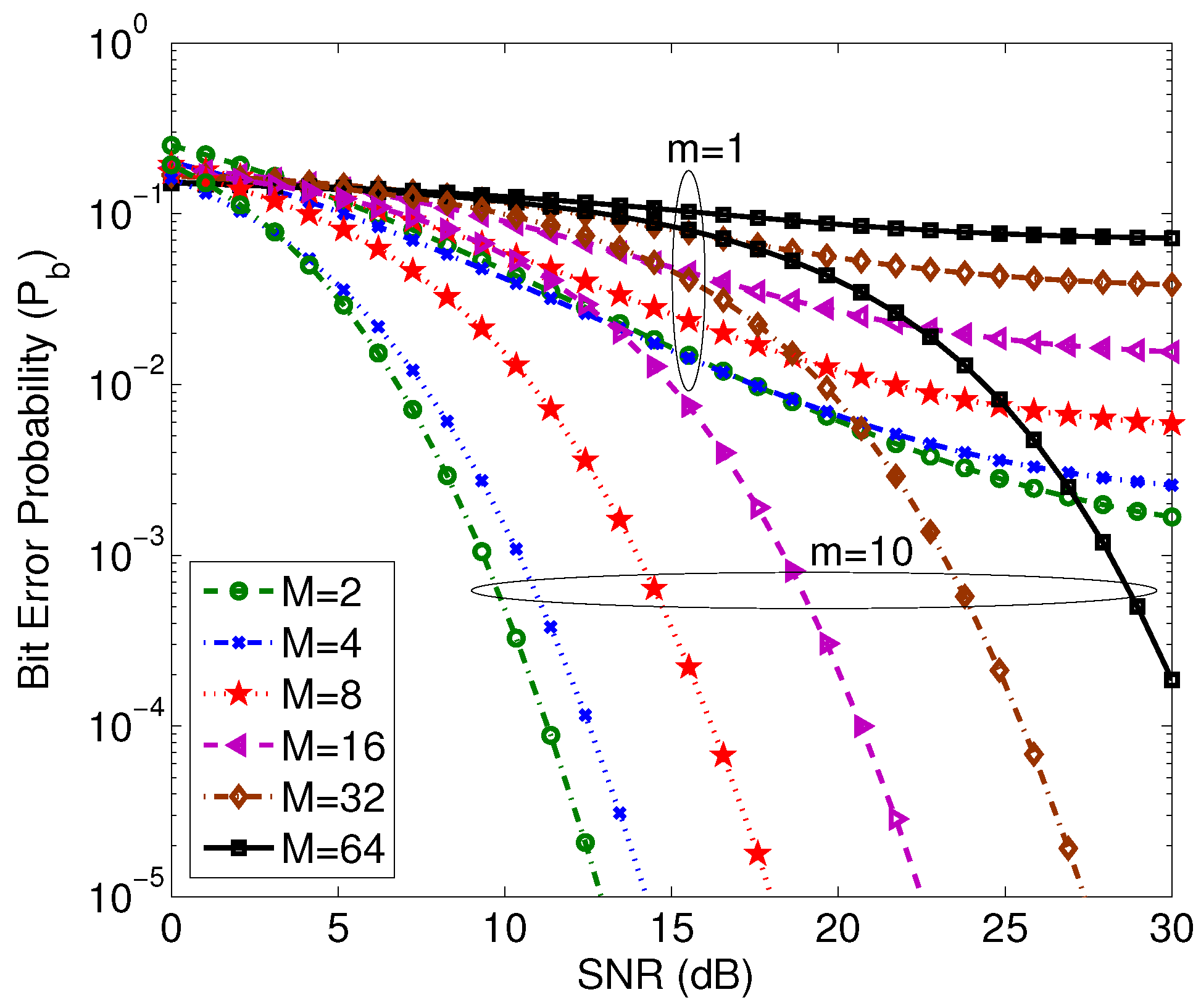
Figure 4b illustrates the probability of error at ns and a bandwidth of 20 MHz, however the number of subcarriers is varied from to 1024. The results indicate that the system performance is in favor of a higher number of subcarriers. We notice that the difference in the probability of error is slightly smaller when the number of subcarriers increases from 256 to 1024. However, utilizing more channels makes the frequency-selective fading almost negligible. The same parameters are repeated for Quadrature differential OFDM () and the results are reported in Figure 5a,b. The probability of error is also calculated for different values of M-ary sizes for 64 subcarriers and 400 ns guard period duration as in Figure 6.
In this paper, the performance of differential-phase OFDM has been investigated in the presence of AWGN and the multipath fading channel with ISI and ICI. A closed form formula for the average signal to noise/interference ratio has been derived. The system probability of error performance is also studied for the differential-phase OFDM under different conditions and parameters. The IEEE 802.11a standard parameters are used in the simulation along with a decaying exponential power delay profile channel. The results indicate that at a low severity Nakagami parameter, the guard period plays an imperative role in improving the system performance when compared to higher severity parameters. The system performance can be significantly improved by increasing the number of subchannels from 8 to 64. The results show that a limited improvement can be added to the system when the number of subchannels is increased to 256 or 1024. This also justifies the use of 64 subchannels in the IEEE 802.11a standard since the system complexity will significantly drop when the number of subchannels is decreased from 1024 to 64 with limited degradation in the system performance occurring.
This work could be expanded in the future with other types of noises to complete the study of differential phase OFDM. The system could also be studied by implementing diversity reception such as equal gain combing (EGC) and maximal ratio combining (MRC) methods. Another featured addition to this work could be studying the differential phase OFDM–CDMA system with direct sequence (DS) and frequency hopping (FH) [22,23,24].
Conflicts of Interest
The author declares no conflict of interest.
References
- Li, J.; Kavehrad, M. Effect of Selective Multipath OFDM systems for broadband Mobile Applications. IEEE Commun. Lett. 1999, 3, 332–334. [Google Scholar]
- Toutounchian, M.A.; Vaughan, R.G. Beamforming for Multiuser MIMO-OFDM Interference Channels with Multipath Diversity. IEEE Trans. Wirel. Commun. 2015, 14, 1213–1224. [Google Scholar] [CrossRef]
- Xu, S.; Kwak, K.S. Suppression of IEEE 802.11a Interference in TH-UWB Systems Using Singular Value Decomposition in Wireless Multipath Channels. J. Commun. Netw. 2008, 10, 63–70. [Google Scholar] [CrossRef]
- Rappaport, T.S.; Heath, R.W.; Daniels, R.C.; Murdock, J.N. Millimeter Waves Wireless Communication; Prentice-Hall, Inc.: Upper Saddle River, NJ, USA, 2015. [Google Scholar]
- Huang, L.C.; Tjhung, T.T.; Lu, J. On the optimum number of OFDM subcarriers in fast Rayleigh fading channels. IEEE J. Commun. Netw. 2001, 3, 1–6. [Google Scholar] [CrossRef]
- Lim, J.-B.; Kim, E.-S.; Park, C.-J.; Won, H.-C.; Kim, K.-H.; Im, G.-H. Bandwidth-efficient OFDM transmission with iterative cyclic prefix reconstruction. IEEE J. Commun. Netw. 2008, 10, 239–252. [Google Scholar] [CrossRef]
- Huang, L.C.; Tjhung, T.T.; Lu, J. A 64-point Fourier transform chip for high-speed wireless LAN application using OFDM. IEEE J. Solid-State Circuits 2004, 39, 484–493. [Google Scholar]
- Rahbari, H.; Krunz, M. Exploiting Frame Preamble Waveforms to Support New Physical-Layer Functions in OFDM-Based 802.11 Systems. IEEE Trans. Wirel. Commun. 2017, 16, 3775–3786. [Google Scholar] [CrossRef]
- Ayach, O.E.; Peters, S.W.; Heath, R.W., Jr. The Feasibility of Interference Alignment Over Measured MIMO-OFDM Channels. IEEE Trans. Veh. Technol. 2010, 59, 4309–4321. [Google Scholar] [CrossRef]
- Abualhaol, I.Y.; Matalgah, M.M.; Abu-Abed, A.S. Enhanced cooperative coding for relay-based MIMO-OFDM systems. In Proceedings of the 21st Annual IEEE International Symposium on Personal, Indoor and Mobile Radio Communications, Istanbul, Turkey, 26–29 September 2010; pp. 2299–2303. [Google Scholar]
- Hermann, R.; May, T. Comparison of PSK and DPSK modulation in a coded OFDM system. In Proceedings of the IEEE 47th Vehicular Technology Conference, Phoenix, AZ, USA, 4–7 May 1997; Volume 2, pp. 870–874. [Google Scholar]
- Ma, Y.; Patzold, M. Performance Analysis of Wideband Sum-of-Cisoids-Based Channel Simulators with Respect to the Bit Error Probability of DPSK OFDM Systems. IEEE Veh. Technol. Conf. 2009, 59, 1–6. [Google Scholar]
- Rappaport, T.S. Wireless Communication; Prentice-Hall, Inc.: Upper Saddle River, NJ, USA, 1996. [Google Scholar]
- Simon, M.K.; Alouni, M.-S. A Unified Approach to the Performance Analysis of Digital Communication over Generalized Fading Channels. Proc. IEEE 1998, 86, 1860–1877. [Google Scholar] [CrossRef]
- Karagiannidis, G.K.; Zogas, D.A.; Kotsopoulos, S.A. Performance analysis of triple selection diversity over exponentially correlated Nakagami-m fading channels. IEEE Trans. Commun. 2003, 81, 1245–1248. [Google Scholar] [CrossRef]
- Proakis, J.G. Digital Communications, 3rd ed.; Mc-Graw-Hill: New York, NY, USA, 1995. [Google Scholar]
- Güvenkaya, E.; Bala, E.; Yang, R.; Arslan, H. Time-Asymmetric and Subcarrier-Specific Pulse Shaping in OFDM-Based Waveforms. IEEE Trans. Veh. Technol. 2015, 64, 5070–5082. [Google Scholar] [CrossRef]
- Stefan, H. Optimum Nyquist Windowing in OFDM Receivers. IEEE Trans. Commun. 2001, 48, 417–420. [Google Scholar]
- Lu, J.; Tjhung, T.; Adachi, F.; Huang, C. BER Performance of OFDM-MDPSK system in frequency-selective Rician fading with diversity reception. IEEE Trans. Veh. Technol. 2000, 49, 1216–1225. [Google Scholar]
- Cimini, L.J. Analysis and simulation of a digital mobile channel using orthogonal frequency division multiplexing. IEEE Trans. Commun. 1985, 33, 665–675. [Google Scholar] [CrossRef]
- Kim, Y.-J.; Im, G.-H. Pilot-Symbol Assisted Power Delay Profile Estimation for MIMO-OFDM Systems. Commun. Lett. 2012, 16, 68–71. [Google Scholar] [CrossRef]
- Zhang, Z.; Tian, F.; Zeng, F.; Ge, L.; Xuan, G. Mutually orthogonal complementary pairs for OFDM-CDMA systems. In Proceedings of the 12th International Conference on Signal Processing (ICSP), HangZhou, China, 19–23 October 2014. [Google Scholar]
- Upadhyay, R.; Tokekar, S.; Vyavahare, P.D. Performance comparison of 802.11 DCF in fading with OFDM and diversity. In Proceedings of the Ninth International Conference on Wireless and Optical Communications Networks (WOCN), Indore, India, 20–22 September 2012. [Google Scholar]
- Choi, J. Coded OFDM-IM With Transmit Diversity. IEEE Trans. Commun. 2017, 65, 3164–3171. [Google Scholar] [CrossRef]
Figure 1.
Block diagram of the transmitter and receiver for the differential-phase OFDM system.
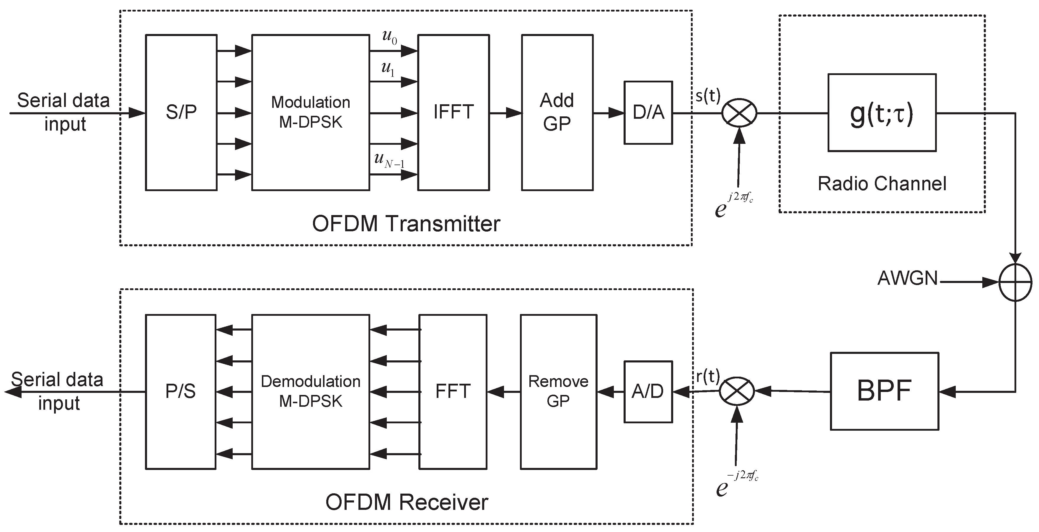
Figure 2.
(a) Received frame from the shortest multipath component and (b) Received frame from the p-th path with .
Figure 2.
(a) Received frame from the shortest multipath component and (b) Received frame from the p-th path with .
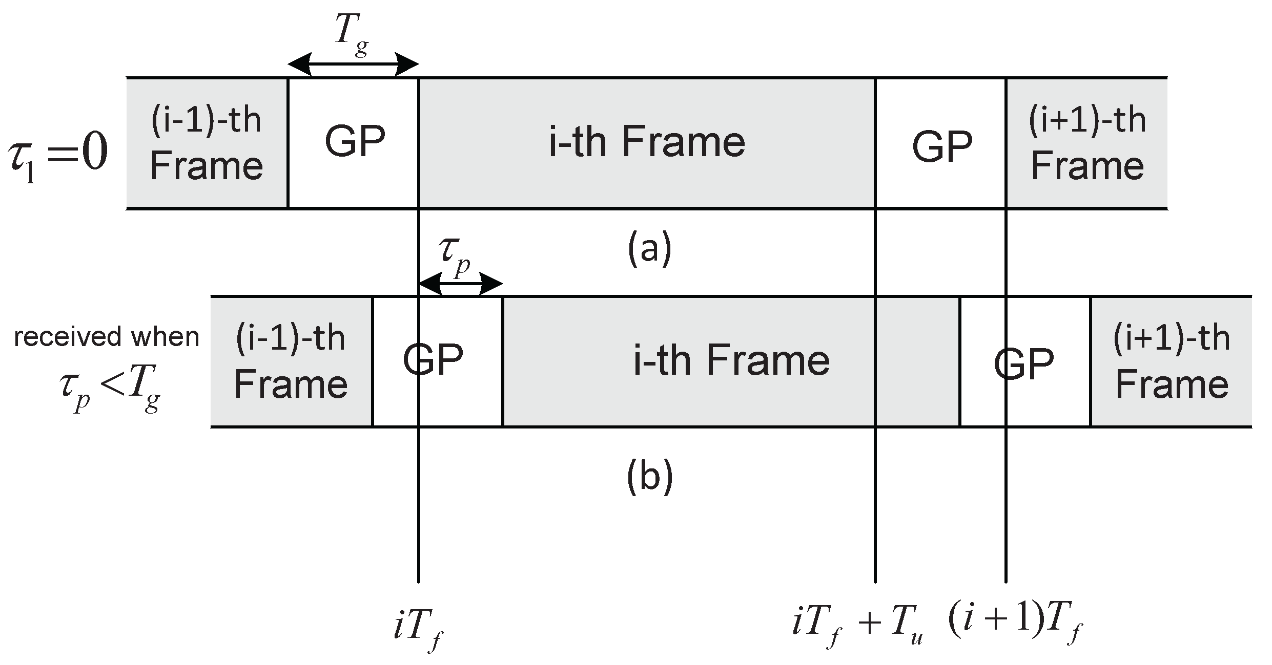
Figure 3.
(a) Received frame from the shortest multipath component and (b) Received frame from the p-th path with .
Figure 3.
(a) Received frame from the shortest multipath component and (b) Received frame from the p-th path with .
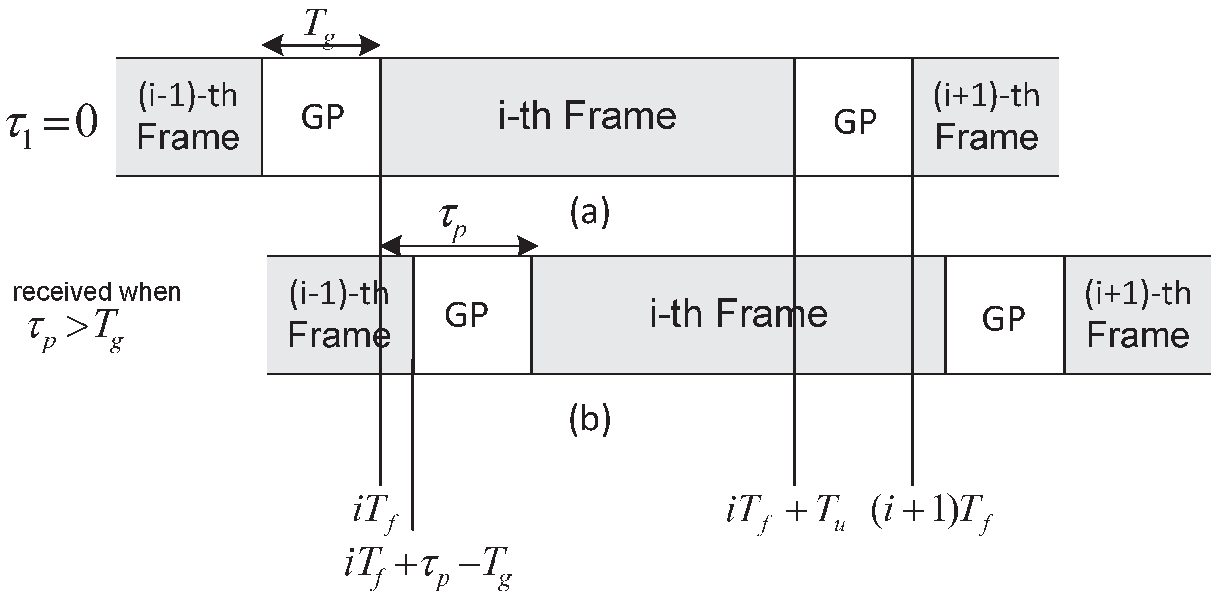
Figure 4.
OFDM–BDPSK system with (a) and different guard period durations and severity parameter (m) values (b) ns and MHz with different numbers of subcarriers and severity parameter (m) values.
Figure 4.
OFDM–BDPSK system with (a) and different guard period durations and severity parameter (m) values (b) ns and MHz with different numbers of subcarriers and severity parameter (m) values.
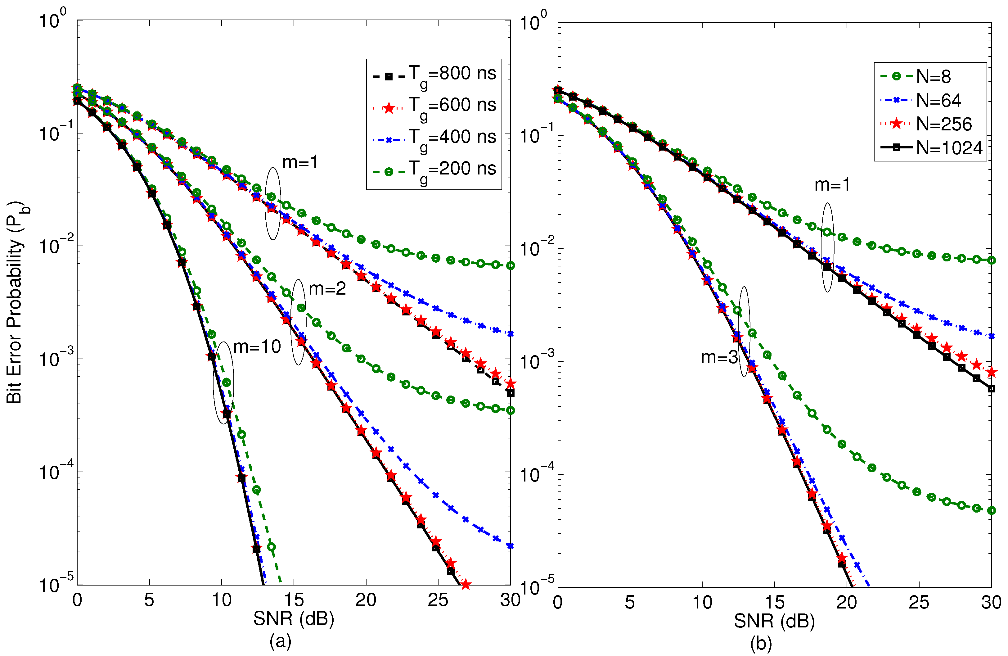
Figure 5.
OFDM–QDPSK system with (a) and different guard period durations and severity parameter (m) values (b) ns and MHz with different numbers of subcarriers and severity parameter (m) values.
Figure 5.
OFDM–QDPSK system with (a) and different guard period durations and severity parameter (m) values (b) ns and MHz with different numbers of subcarriers and severity parameter (m) values.
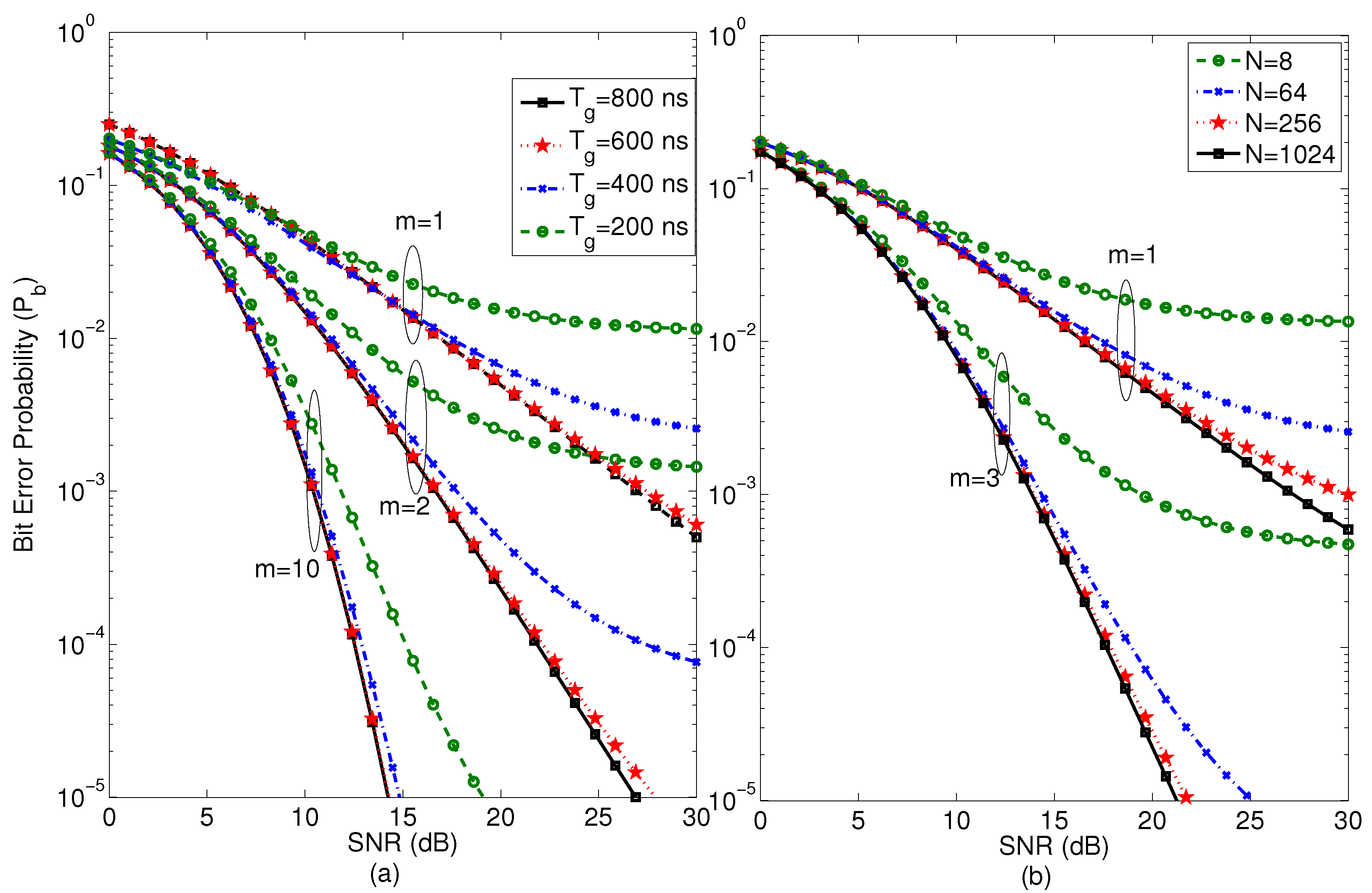
Figure 6.
OFDM–MDPSK system with , ns and different M-ary sizes.


Table 1.
Physical parameters for IEEE 802.11a standard.
| Parameter | Setting |
|---|---|
| Bandwidth () | 20 MHz |
| # of subchannels | N=64 |
| Subcarrier separation () | 312.5 kHz |
| Symbol duration () | 50 ns |
| Data duration () | 3.2 s |
| Guard period () | 200, 200, 600, and 800 ns |
| FFT size | Same as the number of subchannels |
| Fading | Multipath selective |
| Severity parameter m | different integer |
| Power Delay Profile | exponential |
Table 2.
Parameters of Power delay profile: delay spread in (ns) and path loss (dB).
| Delay Spread (ns) | Normalized Path Gain | Path Gain (dB) |
|---|---|---|
| 0 | 1.00 | 0 |
| 100 | 0.4893 | −3.10 |
| 200 | 0.2394 | −6.21 |
| 300 | 0.1171 | −9.31 |
| 400 | 0.0573 | −12.42 |
| 500 | 0.0280 | −15.53 |
| 600 | 0.0137 | −18.63 |
| 700 | 0.0067 | −21.74 |
Table 3.
Average signal-to-interference ratio Vs. the guard period.
| Guard Period (ns) | Frame Duration (s) | % | Average SIR per Frame (dB) |
|---|---|---|---|
| 200 | 3.4 | 5.88% | 19.00 |
| 400 | 3.6 | 11.11% | 26.29 |
| 600 | 3.8 | 15.79% | 36.75 |
| 800 | 4.0 | 20% | No Interference |
© 2017 by the author. Licensee MDPI, Basel, Switzerland. This article is an open access article distributed under the terms and conditions of the Creative Commons Attribution (CC BY) license (http://creativecommons.org/licenses/by/4.0/).
Share and Cite
MDPI and ACS Style
Abuabed, A.S.A. Performance of Differential-Phase OFDM Systems over Selective Multipath Fading Channels. Electronics 2017, 6, 66. https://doi.org/10.3390/electronics6030066
AMA Style
Abuabed ASA. Performance of Differential-Phase OFDM Systems over Selective Multipath Fading Channels. Electronics. 2017; 6(3):66. https://doi.org/10.3390/electronics6030066
Chicago/Turabian StyleAbuabed, Alaeddin S. A. 2017. "Performance of Differential-Phase OFDM Systems over Selective Multipath Fading Channels" Electronics 6, no. 3: 66. https://doi.org/10.3390/electronics6030066
Note that from the first issue of 2016, this journal uses article numbers instead of page numbers. See further details here.