Article

Performance Evaluation of Downlink Multi-Beam Massive MIMO with Simple Transmission Scheme at Both Base and Terminal Stations

1
Faculty of Engineering, Niigata University, Ikarashi 2-nocho 8050, Nishi-ku Niigata 950-2181, Japan
2
Faculty of Engineering, Nippon Institute of Technology, 4-1 Gakuendai, Miyashiro-machi, Minamisaitama-gun, Saitama 345-8501, Japan
*
Author to whom correspondence should be addressed.
Electronics 2017, 6(4), 100; https://doi.org/10.3390/electronics6040100
Submission received: 1 November 2017 / Revised: 13 November 2017 / Accepted: 15 November 2017 / Published: 21 November 2017
(This article belongs to the Special Issue Smart Antennas and MIMO Communications)

Abstract

:
Multi-beam massive multiple-input–multiple-output (MIMO) configurations that utilize high-power beam selection in the analog parts and blind algorithms such as the constant modulus algorithm (CMA), which do not require channel state information (CSI), in the digital parts, have been proposed in the literature to improve the transmission rates and efficiency. In this paper, we evaluate the transmission performance in the downlink, with simple control at the base station (BS) and user terminal (UTs), for massive MIMO transmissions. Through computer simulations, it is shown that the analog multi-beam selection at the BS and the application of CMA at the UT with two antennas can effectively realize transmissions with high-order modulation schemes. In addition, the weight update switching by the CMA is proposed in order to obtain fast and stable performance with a realistic data size.

1. Introduction

The multiuser multiple-input–multiple-output (MU-MIMO) systems have been incorporated into the Long Term Evolution (LTE)-Advanced and IEEE 802.11ac standards [1]. MU-MIMO achieves high-speed communication through advanced signal processing. However, in the IEEE 802.11ac and LTE-Advanced standards, the number of antennas at the base station (BS) can reach up to eight [2]. It has been found that the transmission rate per user in MU-MIMO is reduced severely when the total number of antennas at the user terminals (UTs) approaches the number of antennas at the BS [3,4].
The amount of data being transferred over wireless communication channels is almost doubling every year. Moreover, the total wireless communication traffic volume in 2021 is estimated to be nearly 200 times the traffic volume in 2010 [5,6]. Because of the increase in the number of small cells being introduced in the 5th generation mobile communication systems (5th Generation: 5G) after LTE-Advanced, BSs that can accommodate the further number of users are required [7,8].
Massive MIMO transmission, in which the number of antennas is much larger than the number of UTs, has been attracting much attention as one of the key technologies for the next-generation mobile communication systems, because it enables service area securing and spatial multiplexing in small cells [9,10,11,12]. Massive MIMO has the advantage that the transmission rate is not reduced even if the number of users increases [11].
However, when using transmit beamforming in massive MIMO systems such as MU-MIMO, the communication efficiency decreases considerably because of the channel state information (CSI) feedback from the UTs [3]. As a counter-measure for this, implicit beamforming (IBF) has been proposed [13]. However, even if IBF is implemented in the massive MIMO systems, the CSI estimation itself will be a large overhead when considering short packet communications such as that in wireless local area network (LAN) systems [3].
The authors proposed an analog–digital hybrid massive MIMO configuration that eliminates CSI estimation, in a previous work [14]. In conventional analog–digital hybrid massive MIMO configurations [15,16], a beam scanning is required for user tracking in each sub-array, and overheads are incurred in determining the analog weight values. In the proposed configuration, unlike conventional analog–digital hybrid massive MIMO configurations, analog multi-beams are created and several beams with large received powers are selected in the analog part without the overhead for the beamforming [14]. Owing to the selected narrow beams, interference signals can be mitigated, and the residual interference can be cancelled using the constant modulus algorithm (CMA) [17], which does not require training signals in the digital part. Via computer simulations, the basic performance and effectiveness of the uplink channel is evaluated, for the proposed method [14,18].
Previous studies regarding multi-beam massive MIMO mainly focused on the uplink channel [14,18]. However, in the next-generation wireless communication systems, including the latest wireless communication systems, the data rate improvement in the downlink channel is essential, and massive MIMO is mainly expected to improve the transmission rate in the downlink.
In this paper, we propose a transmission beamforming method that uses multi-beam massive MIMO configuration and control method in the uplink channel; the proposed method does not require CSI in the downlink. It is necessary to consider the control of the analog part and the digital part in the downlink respectively, because the proposed configuration employs the analog–digital hybrid method, unlike conventional digital beamforming (DBF). In this paper, first, we verify the effectiveness of the analog part using analog weight which is selected in the uplink channel alone. Owing to the selected narrow beams, it is shown that the interference signals can be mitigated. However, when the angle of arrivals (AoAs) are close among users, we show that the effect of the analog part is not sufficient. In order to solve this problem, we propose using the CMA for the UT side as well as the elimination of the CSI estimation at the BS. In addition, we propose a method combining the least-square CMA (LS-CMA) and the steepest-descent CMA (SD-CMA) methods in order to utilize CMA stably, with realistic data sizes even for high-order modulation schemes. Finally, the effectiveness of the proposed method is verified using the evaluation of the signal to interference plus noise power ratio (SINR) and the bit rate by the bit error rate (BER).
The remainder of this paper is organized as follows. In Section 2, we describe the principle of analog multi-beam massive MIMO with CMA in the digital part. In Section 3, we show the proposed configuration and propose the control method for the downlink. Moreover, the basic performances are presented to verify the effectiveness of the proposed method. In Section 4, the issues related to CMA when using quadrature amplitude modulated (QAM) signals are discussed, and the solution combining the LS-CMA and SD-CMA is presented. The performances with realistic data sizes are presented to verify the effectiveness of the proposed method.

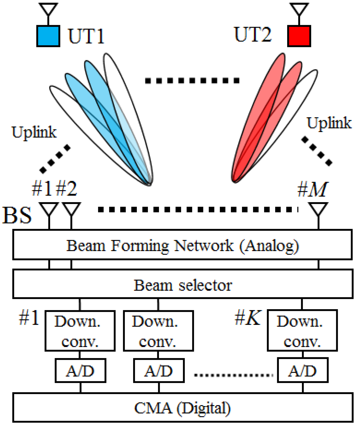
2. Multi-Beam Massive MIMO Configuration Using CMA in the Uplink

2.1. Multi-Beam Massive MIMO Configuration Using CMA

Figure 1 shows the configuration of the uplink using analog multi-beam, and CMA for the digital part [14,18]. This system only has been proposed configuration and control methods for uplink. In the proposed method, first, M orthogonal multiple beams are prepared in analog part. It is well known that the Butler matrix [19] and lens antenna realize a multi-beam forming network [20,21]. A trial circuit example using a Butler matrix circuit is presented in [22].
Second, the received powers for all users are measured at the outputs of multiple beams. Using several beams, selected according to the powers of all analog multi-beams, the UTs can be separated.
MU-MIMO transmission without CSI estimation for each user is realized by the proposed system. However, when the AoAs are close among users, signals from multiple users are received in the same beam. Moreover, the signals from users other than the intended user are actually received at the sidelobes and the interference cannot be rejected by the multi-beam forming network alone. In order to realize perfect interference rejection, DBF based blind adaptive arrays are introduced at the outputs of the selected multi-beams.
The proposed configuration can be regarded as a fast Fourier transform (FFT)-based CMA adaptive array [23]. The configuration in [23] is the DBF configuration, and multi-beam forming network is used in the digital parts. On the other hand, the main feature of proposed configuration is that multi-beams are realized in the analog part. Therefore, the number of frequency converters and analog-to-digital/digital-to-analog converters can be reduced, unlike in the DBF configuration. Moreover, the transmission timings of the UTs need not be synchronized.

2.2. Principle of CMA

The principle of CMA is explained in this section. The CMA is categorized as a blind adaptive array algorithm, because it requires information of received signals only. Because CSI estimation is not needed when using CMA, the communication efficiency is improved greatly. In addition, the CMA is not affected by the carrier or timing offsets. The cost function Q of CMA is expressed as
Q ( W ) = E | y ( t ) | p σ p q = E | | W H X ( t ) | p σ p | q
where y is the output voltage of the array and σ ( > 0 ) is a constant value, which is usually set to be the power of the desired signal. Symbols p and q are positive integers with values of one or two. The weight of each element is controlled so that (1) is minimized. Although the weight of the CMA adaptive array is updated by using (1), it is not possible to express the optimum weight directly in the closed form, because (1) is nonlinear with respect to the weight. Therefore, the weight of CMA is controlled by an asymptotic technique such as SD-CMA so that (1) is minimized.
If the weight and the cost function after m iterations are W ( m ) and Q ( m ) , respectively, the weight updating equation using SD-CMA can be expressed as
W ( m + 1 ) = W ( m ) μ W Q ( m )
where m is the number of repetitions (iterations) of the weight update, and μ is the step size. In addition, W Q ( m ) is the slope vector of Q with respect to W . In the SD-CMA, the step size determines the convergence characteristics of the weight in the CMA adaptive array. In order to improve the performance of the CMA adaptive array, LS-CMA is proposed [24]. Because the convergence of weight in LS-CMA is more rapid than that in SD-CMA, LS-CMA is used for the uplink. The weight updating equation by LS-CMA is denoted by
W ( m + 1 ) = W ( m ) i = 1 n X ( i ) X H ( i ) 1 i = 1 n X ( i ) y * ( i ) δ * ( i ) = i = 1 n X ( i ) X H ( i ) 1 i = 1 n X ( i ) δ * ( i ) 1
δ * ( i ) = σ | y ( i ) | y ( i )
where X ( i ) ( i = 1 , , n ) and y ( i ) ( i = 1 , , n ) are the input vector and output signal, respectively, at the i-th sample.

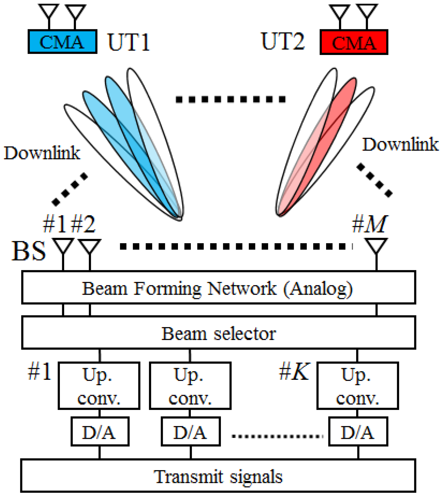
3. Proposed Configuration and Beamforming Method Eliminating CSI in the Downlink

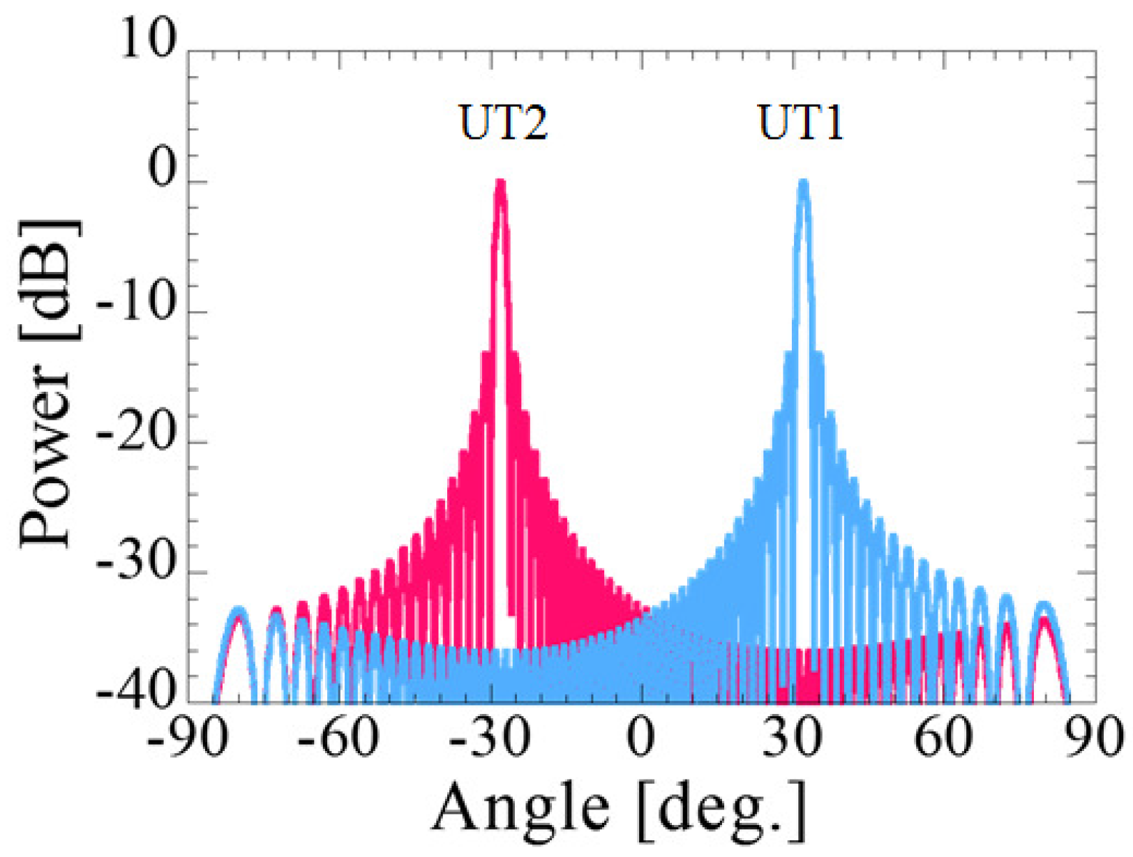
3.1. Configuration in Downlink and Beam Patterns Using Analog Weight

Figure 2 shows the configuration of the multi-beam massive MIMO for the downlink with CMA implemented at the UT. In the case of the downlink, only directed beams are used for the UTs. Figure 3 shows an example selected beam for the uplink channel, when the direction of UT1 is 30 degrees and the direction of UT2 is −30 degrees. The center direction of the BS is set to 0 degree. Because the peaks of the main beams selected on the uplink channel are directed toward each UT, the beams selected on the uplink are used in the downlink also. Each UT receives the desired signals at the main lobes of the beams facing the UT, and they receive the interference signals from the sidelobes of the beams facing the other UTs. However, as shown in Figure 2, the sidelobe level of UT2 directed toward UT1 is lower than the main lobe level of UT1. Therefore, UTs can be separated in the downlink by using the selected beams of the uplink channel without any calculation in the signal processing part thanks to analog multi-beams.

3.2. Residual Interference Elimination Method at the UTs

Although the separation of multiple users can be achieved by the configuration as described in Section 3.1, the interference signals are still received by the sidelobes of the beams facing the other UTs. In order to realize perfect interference rejection at the UTs, CMA is applied at the UT with two antennas as the simplest configuration and elimination of the CSI estimation. In this paper, LS-CMA is also used at the UTs. The interference signals are suppressed by the CMA and finally, only the desired signals are received at the UTs.

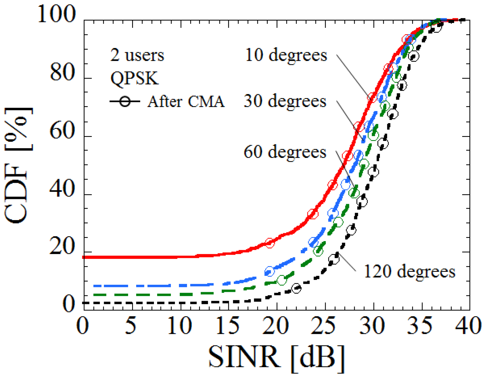
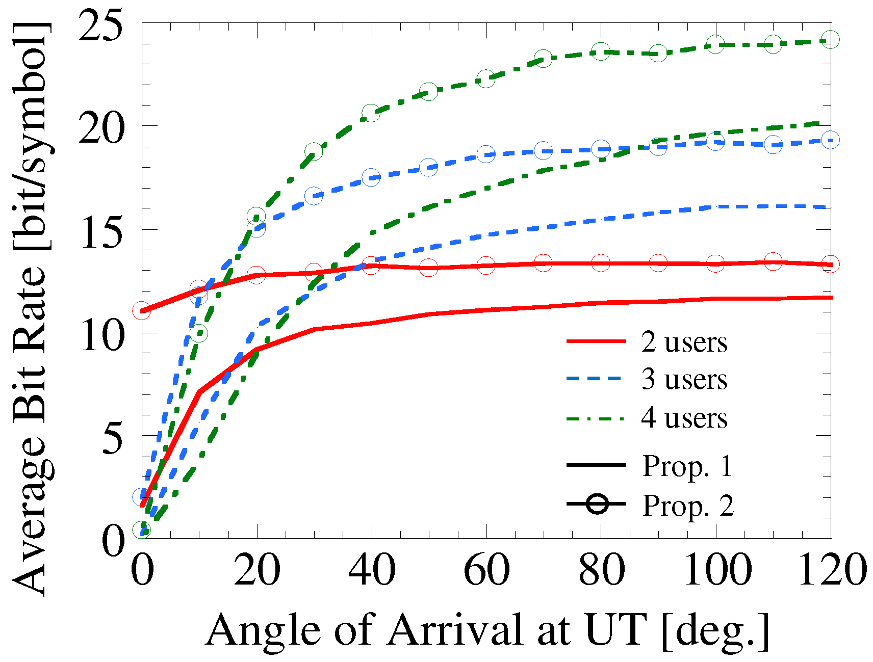
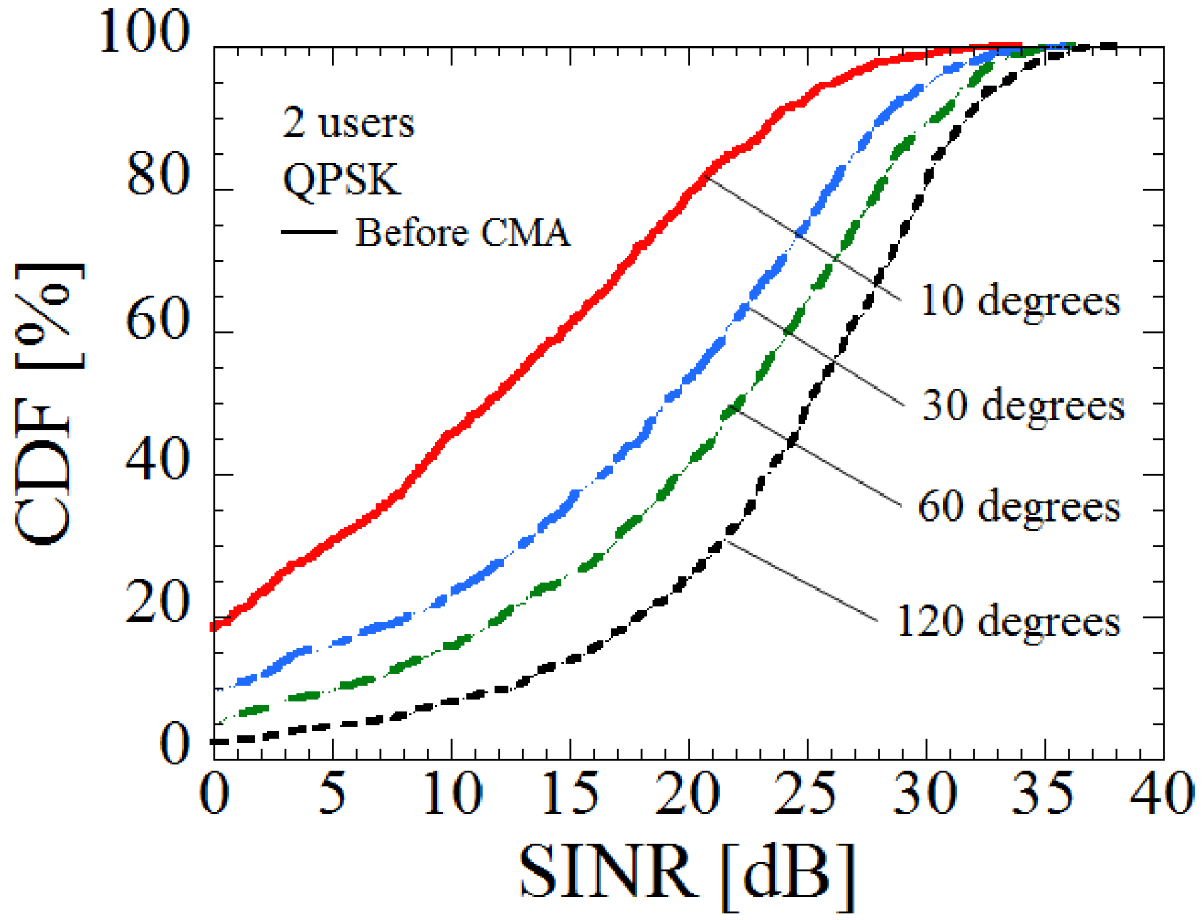
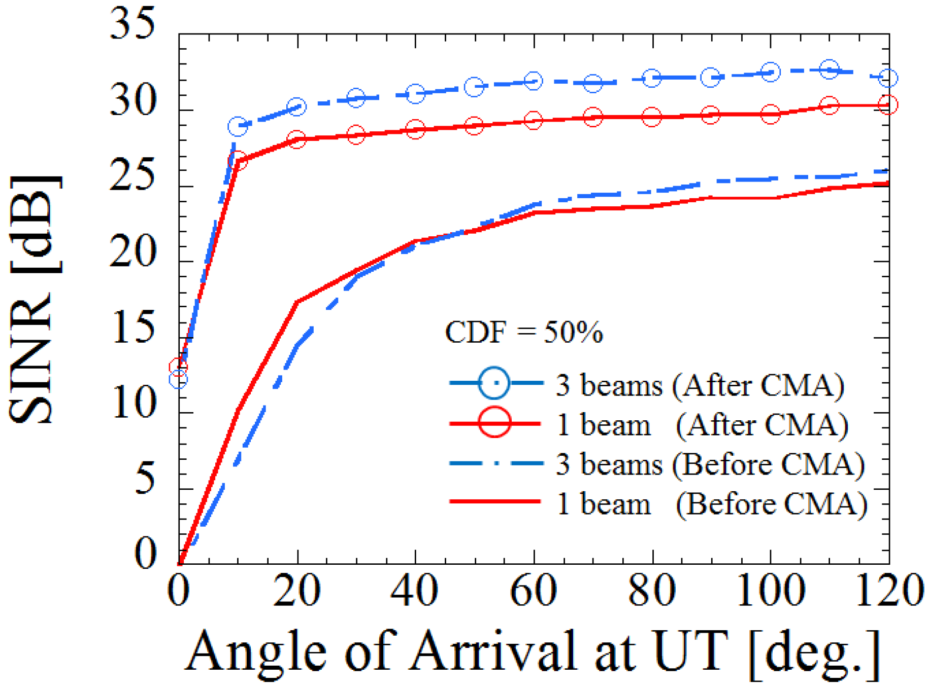
3.3. Effectiveness of Proposed Configuration and Method Through Computer Simulations

The effectiveness of the proposed configuration and method is verified using QAM signals (4QAM to 1024QAM) on the downlink, considering a Rayleigh fading environment. By comparing the transmission signals and the demodulated received signals, the BER is derived. The modulation scheme with maximum bit rate is selected when the BER is less than 10−3 [25]. If the BER is greater than 10−3, we assume that the bit rate is zero. In this way, we derive the bit rate considering the angular difference between the receiving UTs.
Table 1 shows the simulation conditions. Because it is assumed that the channel reciprocity between the transmission and reception is guaranteed in 5G system where time division duplex (TDD) operation with the high data rate is used [10], this simulation is performed in a static environment between the transmission and reception to verify the basic performance of the proposed system. As the future work, we should evaluate the performance when considering the Doppler shift. In order to evaluate pure interference rejection by the proposed method, the SNR is set to be 30 dB. In the simulation, we focus on evaluating the ideal performance at the UTs by securing a sufficient number of symbols and iterations so that the weight of the CMA converges ideally even when using QAM signals.
In order to evaluate the performance using beam control alone, Figure 4 shows the cumulative density function (CDF) versus signal-to-interference-plus-noise power ratio (SINR), when the difference in the AoA between two UTs is set to be 10, 30, 60, or 120 degrees. The SINR is improved according to the increase in the AoA between two users. This result shows that the UTs can be separated by analog beam patterns at the BS. However, as can be seen in Figure 3, user separation is not perfect because the interference signals are still received by the sidelobes of the beams facing the other UTs.
Figure 5 shows the CDF versus SINR when the residual interference of Figure 4 is cancelled by using CMA at the UTs. In the case of relatively close AoAs between two UTs, such as 10 degrees, the SINR is greatly improved by applying CMA. Moreover, the SINR is improved even if the AoAs between two UTs are relatively large, such as 120 degrees. However, in CMA, because the signals of maximum power among the received signals are regarded as the desired signals, erroneous signals may be extracted if the received powers of the interference signals are higher than that of the desired signals. Therefore, the SINR drops extremely by applying CMA when the SINR is less than 0 dB. This problem occurs when the beams selected for different users are close. It can be improved by implementing beam selection that does not select close beams in the uplink.
Next, we increase the number of beams used for transmission in order to improve the performance. The power of the desired signals increases when using the adjacent beam along with the selected beams of the uplink channel, if considering the angular spread. Therefore, it is possible to improve the transmission rate in an environment with low SNR. When a large number of beams are used, Doppler effects which are caused by the movement of the UTs are also mitigated, because total beam pattern is regarded as the omni-directional. However, because the power of the interference signals also increases, interference cancellation at the UTs is essential.
Figure 6 shows the SINR versus AoA at the UTs when the number of beams is one or three. The amount of increase in the desired power and the interference power due to the increase in the number of beams are different depending on the AoAs between two UTs. In the case of relatively close AoAs between two UTs, because the influence of the sidelobes of the beams facing the other UTs is large, the interference power is increased. On the other hand, in the case of relatively large AoAs between two UTs, because the influence of the sidelobes of the beams facing the other UTs is small, the SINR is improved. Moreover, by applying CMA at the UTs, the SINR is improved even when the AoA between two UTs is close. Incidentally, it has been confirmed that the SINR does not improve any further even when the beam number is increased from three.
Finally, the effectiveness of the proposed configuration and method, which does not need CSI in the downlink, is verified based on the bit rate. Figure 7 shows the average bit rate versus the AoA at the UTs when the number of UTs is two, three and four. In Figure 7, the modulation scheme with maximum bit rate is selected when the BER is less than 10−3. We compare the case of transmitting with one beam without CMA (Prop. 1) in Figure 7 and the case of applying CMA at the UTs after transmitting with the optimum number of beams (Prop. 2) in Figure 7. The bit rate is decreased because the total interference power is increased when the number of UTs is increased. However, owing to the CMA at the UT, the average bit rate is improved even if the number of users is increased. The result indicates that the performance is improved greatly by the proposed configuration and CMA at UTs.

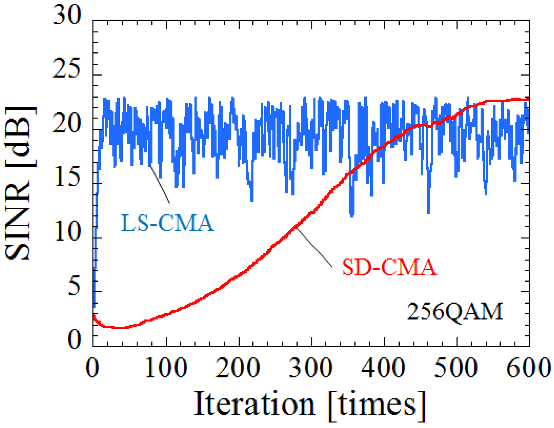
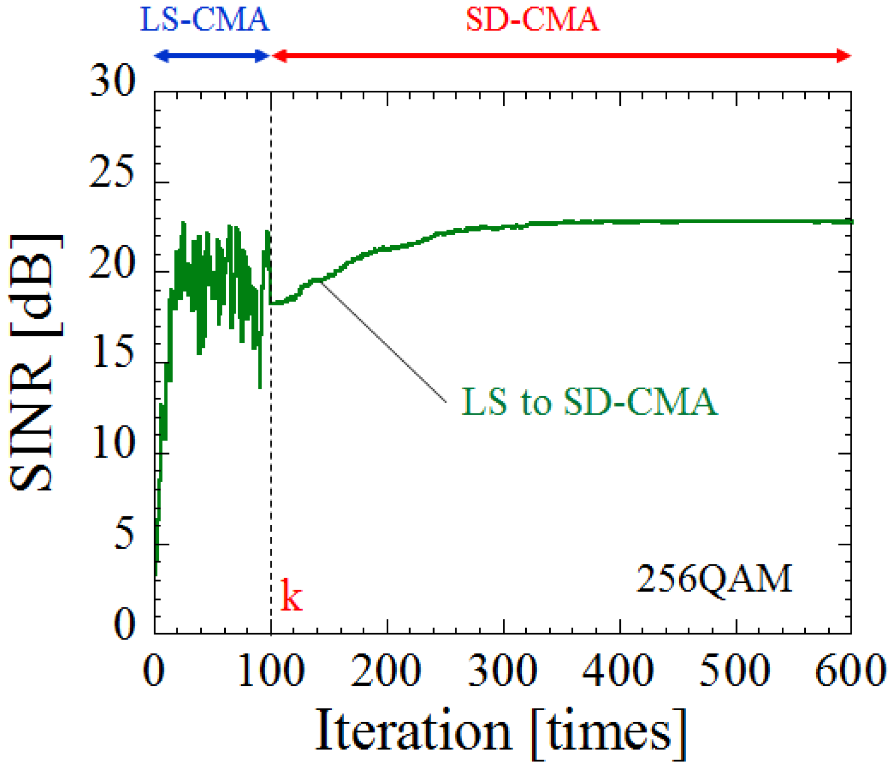
4. Modified Weight Update Method by LS-CMA and SD-CMA

4.1. Issue on LS-CMA Snd Switching Algorithm of CMA

In Section 3, the ideal performance of the proposed method, where the sufficient iteration and data smoothing number by CMA is given, was verified. Next, assuming that the CMA operates in an actual system, we focus on evaluating the performance for realistic data sizes, because, it is not possible to secure the large number of symbols required for controlling the weights. Although CMA focuses on modulation schemes with constant modulus, such as the Gaussian minimum shift keying (GMSK) or quadrature phase shift keying (QPSK) [17], it has been reported that QAM signals can also be used [18,26,27].
Figure 8 shows the SINR by the weight update using LS-CMA and SD-CMA versus the iteration, when the AoA between two UTs is 60 degree and the smoothing size is 100 symbols for both. In the case of the LS-CMA method, convergence is rapid because the fluctuation in weight is large with one update. However, as can be seen in Figure 8, the weight does not stabilize after convergence. This issue can be solved by using data smoothing wherein the weights of the CMA are averaged for multiple samples. However, the number of symbols used increases according to the increase in the smoothing sizes. On the other hand, in the case of the SD-CMA method, the weight stabilizes after convergence because the fluctuation in weight is small with one update. Therefore, we propose a method that combines the LS-CMA and the SD-CMA approaches.
When the total number of weight updates is n, the weight is updated ( 1 , 2 , , k ) times with the (3), which is the expression for the LS-CMA method. Next, using that weight, the weight is updated ( k + 1 , k + 2 , , n ) times with the (2) which is the expression for the SD-CMA method. Hence, speed improvement and stabilization of weight convergence can be realized. In this paper, this proposed method is called the LS-to-SD-CMA.

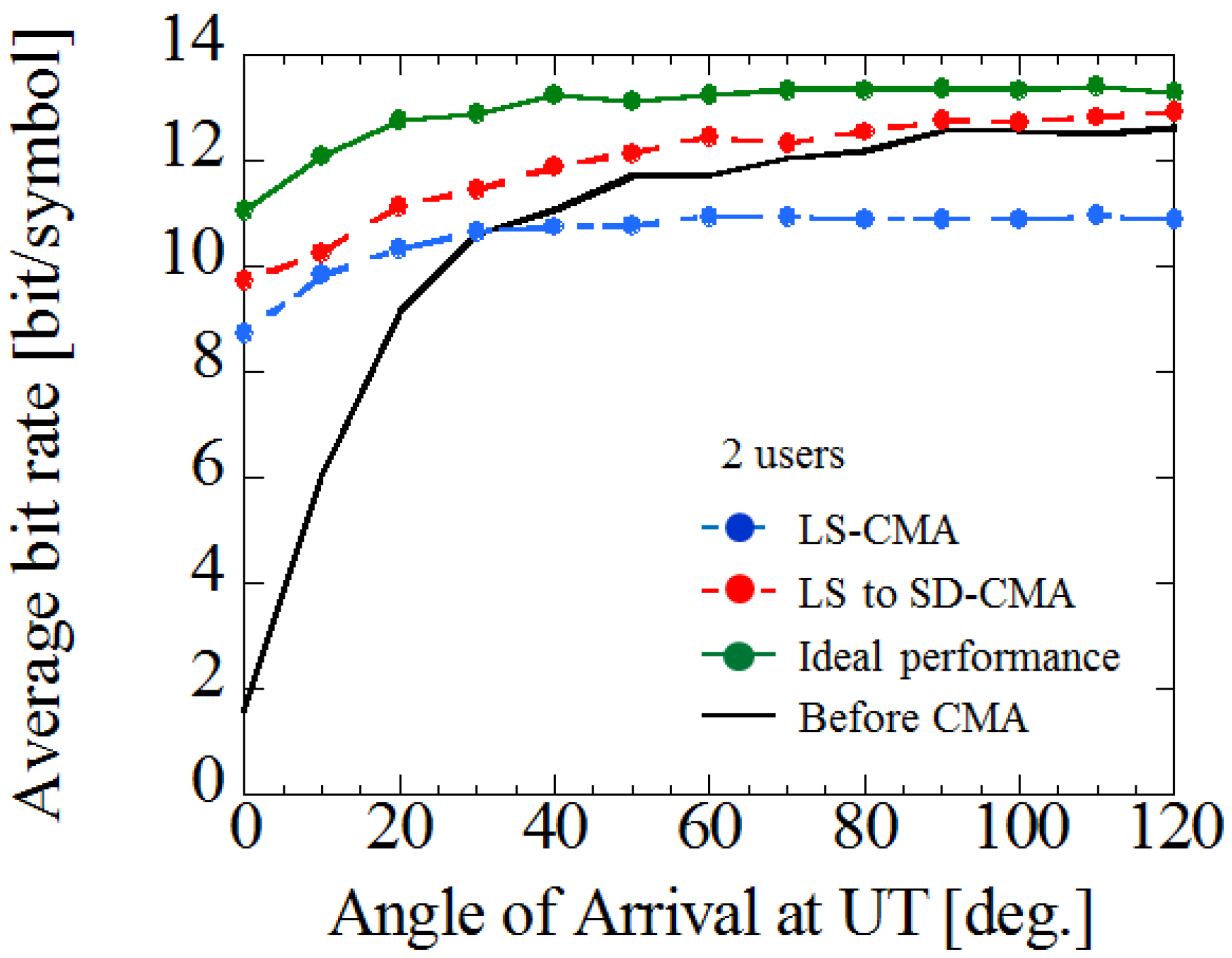
4.2. Effectiveness of Proposed Method Verified through Computer Simulations

The effectiveness of proposed method is verified through computer simulations. Figure 9 shows the SINR by weight update of the LS-to-SD-CMA versus iteration. The parameters are the same as those in Figure 8. As can be seen from Figure 9, in the LS-to-SD-CMA method, a high SINR is maintained after the SINR is improved with the first few updates. Because the weight stabilizes without increasing the smoothing sizes as in LS-CMA, it is possible to reduce the number of symbols.
Finally, by using the LS-to-SD-CMA, the effectiveness of the proposed method is verified for the downlink. Figure 10 shows the average bit rate versus AoA at the UTs when the LS-CMA or LS-to-SD-CMA is applied. Table 2 shows the simulation conditions of the smoothing size and the iteration. Moreover, in order to reduce the amount of calculations and stabilize the CMA, the LS-to-SD-CMA is not applied when a high SINR has already been obtained by only analog beam patterns. As can be seen in Figure 10, in the case of LS-CMA, the bit rate decreases to a value less than the value before applying CMA, when the number of smoothing size is small. However, by applying the proposed method, even with the same number of smoothing size, the performance is improved than when using only beam control. In addition, because this result is approaching the ideal performance securing a sufficient number of symbols and iterations, this control method in the downlink is effective with realistic data sizes.

5. Conclusions

In this paper, a simple control method for the downlink of multi-beam massive MIMO, which did not need CSI estimation at both BS ans UTs, was proposed. The effectiveness of proposed method was verified through computer simulations. It was shown that the analog multi-beam selection at the BS, and the application of CMA to the UTs with two antennas, could realize transmissions with high-order modulation schemes effectively. Moreover, by using LS-to-SD–CMA, it was shown that the proposed method was effective even for realistic data sizes.

Acknowledgments

Part of this work was supported by the SCOPE #165004002 and KAKENHI, Grant-in-Aid for Scientific Research (B) (17H03262, 17H01738).

Author Contributions

This study was led by S.O. while K.N., R.T., T.H. and T.M. assisted with the computer simulations.

Conflicts of Interest

The authors declare no conflict of interest.

References

  1. Gesbert, D.; Kountouris, M.; Heath, R.W., Jr.; Chae, C.-B.; Salzer, T. Shifting the MIMO Paradigm. IEEE Signal Process. Mag. 2007, 24, 36–46. [Google Scholar] [CrossRef]
  2. IEEE P802.11ac./D5.0, Part 11: Wireless LAN Medium Access Control (MAC and Physical Layer (PHY) specifications. Available online: http://ieeexplore.ieee.org/servlet/opac?punumber=6560343 (accessed on 20 November 2017).
  3. Hiraguri, T.; Nishimori, K. Survey of transmission methods and efficiency using MIMO technologies for wireless LAN systems. IEICE Trans. Commun. 2015, E98-B, 1250–1267. [Google Scholar] [CrossRef]
  4. Nishimori, K.; Hiraguri, T.; Makino, H. Transmission Rate by User Antenna Selection for Block Diagonalization Based Multiuser MIMO System. IEICE Trans. Commun. 2014, E97-B, 2118–2126. [Google Scholar] [CrossRef]
  5. Cisco Visual Networking Index: Global Mobile Data Traffic Forecast Update, 2010–2015. Available online: https://ja.scribd.com/document/49195955/Cisco-Global-Mobile-Data-Traffic-Forecast-Update-2010-2015-Feb-11 (accessed on 20 November 2017).
  6. Cisco Visual Networking Index: Global Mobile Data Traffic Forecast Update, 2016–2021. Available online: https://www.cisco.com/c/en/us/solutions/collateral/service-provider/visual-networking-index-vni/mobile-white-paper-c11-520862.html (accessed on 20 November 2017).
  7. Nakamura, T.; Nagata, S.; Benjebbour, A.; Kishiyama, Y.; Hai, T.; Xiaodong, S.; Ning, Y.; Nan, L. Trends in Small Cell Enhancements in LTE Advanced. IEEE Commun. Mag. 2013, 51, 98–105. [Google Scholar] [CrossRef]
  8. Kishiyama, Y.; Benjebbour, A.; Nakamura, T.; Ishii, H. Future Steps of LTE-A Evolution Toward Integration of Local Area and Wide Area Systems. IEEE Wirel. Commun. 2013, 20, 12–18. [Google Scholar]
  9. Larsson, E.G. Very Large MIMO systems. In Proceedings of the ICASSP 2012—IEEE International Conference on Acoustics, Speech and Signal Processing, Kyoto, Japan, 25–30 March 2012. [Google Scholar]
  10. Rusek, F.; Persson, D.; Lau, B.K.; Larsson, E.G.; Marzetta, T.L.; Edfors, O.; Tufvesson, F. Scaling Up MIMO: Opportunities and Challenges with Very Large Arrays. IEEE Signal Process. Mag. 2013, 30, 40–60. [Google Scholar] [CrossRef]
  11. Hoydis, J.; ten Brink, S.; Debbah, M. Massive MIMO in the UL/DL of Cellular Networks: How Many Antennas Do We Need? IEEE J. Sel. Areas Commun. 2013, 31, 160–171. [Google Scholar] [CrossRef] [Green Version]
  12. Papadopoulos, H.; Wang, C.; Bursalioglu, O.; Hou, X.; Kishiyama, Y. Massive MIMO Technologies and Challenges towards 5G. IEICE Trans. Commun. 2016, E99-B, 602–621. [Google Scholar] [CrossRef]
  13. Murakami, T.; Fukuzono, H.; Takatori, Y.; Mizoguchi, M. Multiuser MIMO with Implicit Channel Feedback in Massive Antenna Systems. IEICE Commun.Express 2013, 2, 336–342. [Google Scholar] [CrossRef]
  14. Nishimori, K.; Hiraguri, T.; Seki, T.; Yamada, H. Multi-beam Massive MIMO Using Analog Beamforming and DBF Based Blind Algorithm. In Proceedings of the 2015 International Symposium Antennas and Propagation (ISAP), Hobart, Australia, 9–12 November 2015. [Google Scholar]
  15. Hou, X.; Jiang, H.; Kayama, H.; Xi, W. A Novel Hybrid Beamforming Transmission Scheme for Common Channels and Signals. In Proceedings of the 2015 21st Asisa-Pacific Conference on Communications, Kyoto, Japan, 14–16 October 2015. [Google Scholar]
  16. Geng, J.; Wei, Z.; Wang, X.; Xiang, W.; Yang, D. Multiuser Hybrid Analog/Digital Beamforming for Relatively Large-scale Antenna Arrays. In Proceedings of the 2013 IEEE Globecom Workshops, Atlanta, GA, USA, 9–13 December 2013. [Google Scholar]
  17. Treichler, J.R.; Agee, B.G. A New Approach to Multipath Correction of Constant Modulus Signals. IEEE Trans. Acoust. Speech Signal Process. 1983, 31, 459–472. [Google Scholar] [CrossRef]
  18. Taniguchi, R.; Nishimori, K.; Makino, H. Multi-beam Massive MIMO using Constant Modulus Algorithm for QAM Signal employing Amplitude and Phase Offset Compensation. IEICE Trans. Commun. 2017, E100-B, 262–268. [Google Scholar] [CrossRef]
  19. Butler, J.; Lowe, R. Beamforming Matrix Simplifies Design of Electronically Scanned Antennas. Electron. Des. 1961, 9, 170–173. [Google Scholar]
  20. Zeng, Y.; Zhang, R.; Chen, Z.N. Electromagnetic Lens-Focusing Antenna Enabled Massive MIMO. In Proceedings of the IEEE/CIC International Conference Communication in China (ICCC), Xi’an, China, 12–14 August 2013; pp. 454–459. [Google Scholar]
  21. Heath, R.W., Jr.; Gonzalez-Prelcic, N.; Rangan, S.; Roh, W.; Sayeed, A. An Overview of Signal Processing Techniques for Millimeter Wave MIMO Systems. IEEE J.Sel. Top. Signal Process. 2016, 10, 436–453. [Google Scholar] [CrossRef]
  22. Yamamoto, S.-I.; Hirokawa, J.; Ando, M. A Single-Layer Hollow-Waveguide 8-Way Butler Matrix with Modified Phase Shifters. In Proceedings of the ISAP2005, Seoul, Korea, 3–5 August 2005. [Google Scholar]
  23. Tanaka, T.; Miura, R.; Chiba, I.; Karasawa, Y. An ASIC Implementation Scheme to Realize a BeamSpace CMA Adaptive Array Antenna. IEICE Trans. Commun. 1995, E78-B, 1467–1473. [Google Scholar]
  24. Agee, B.G. The Least-Square CMA: A New Technique for Rapid Correction of Constant Modulus Signals. In Proceedings of the IEEE International Conference on ICASSP ’86 Acoustics, Speech, and Signal Processing, Tokyo, Japan, 7–11 April 1986; pp. 953–956. [Google Scholar]
  25. Nishimori, K.; Yomo, H.; Popovski, P. Distributed Interference Cancellation for Cognitive Radios using Periodic Signals of the Primary System. IEEE Trans. Wirel. Commun. 2011, 10, 2791–2981. [Google Scholar]
  26. Kikuma, K.; Takai, K.; Nishimori, K.; Saito, F.; Inagaki, N. Consideration on Performance of the CMA Adaptive Array Antenna for 16QAM Signals. In Proceedings of the Personal, Indoor and Mobile Radio Communications (PIMRC) 1995, Toronto, ON, Canada, 27–29 September 1995; Volume 2, pp. 677–681. [Google Scholar]
  27. Nishimori, K.; Kikuma, K.; Inagaki, N. Performance analysis of CMA adaptive array for QAM signals. Electron. Commun. Jpn. (Part 1 Commun.) 1997, 80, 11–21. [Google Scholar] [CrossRef]
Figure 1. Configuration of the multi-beam massive multiple-input–multiple-output (MIMO) in uplink.
Electronics 06 00100 g001
Figure 2. Configuration of multi-beam massive MIMO in downlink.
Electronics 06 00100 g002
Figure 3. An example of analog beam patterns selected on the uplink channel.
Electronics 06 00100 g003
Figure 4. Cumulative density function (CDF) versus signal-to-interference-plus-noise power ratio (SINR) by analog beam patterns at base station (BS).
Electronics 06 00100 g004
Figure 5. CDF versus SINR by analog beam patterns at BS and applying CMA at UTs.
Electronics 06 00100 g005
Figure 6. SINR versus angle of arrival (AoA) at UTs.
Electronics 06 00100 g006
Figure 7. Average bit rate versus AoA at UTs.
Electronics 06 00100 g007
Figure 8. SINR by weight update of LS-CMA and SD-CMA versus iteration.
Electronics 06 00100 g008
Figure 9. SINR by weight update of least-square to steepest-descent-CMA (LS-to-SD-CMA) versus iteration.
Electronics 06 00100 g009
Figure 10. Average bit rate versus AoA at UTs using LS-to-SD-CMA.
Electronics 06 00100 g010
Table 1. Simulation conditions.
ParameterValue
Number of Transmission antennas64
Number of receive user terminals (UTs)2
Angular difference between receive UTs0∼120 degrees
Number of receive antennas at each UT2
Number of beams1∼3
Symbol length10000 symbols
Least-square constant modulus algorithm (LS-CMA) smoothing size500 symbols
Number of pilot signals5 symbols
Number of trials1000 times
Average signal to noise power ratio (SNR)30 dB
Table 2. Simulation conditios of the smoothing size.
Smoothing SizeIteration
LS-CMA5020
least-square to steepest-descent-CMA (LS-to-SD-CMA)5020
Ideal performance50020

