Fiber Bragg Grating Sensors for Mainstream Industrial Processes


1
School of Biomedical Sciences, The University of Western Australia, Perth, WA 6009, Australia
2
School of Engineering, RMIT University, Melbourne, VIC 3000, Australia
3
School of Science, Edith Cowan University, Perth, WA 6027, Australia
4
Centre for Communications and Electronics Research (CCER), School of Engineering, Edith Cowan University, Perth, WA 6027, Australia
*
Author to whom correspondence should be addressed.
Electronics 2017, 6(4), 92; https://doi.org/10.3390/electronics6040092
Submission received: 15 September 2017
/
Revised: 30 September 2017
/
Accepted: 16 October 2017
/
Published: 28 October 2017
Abstract
:This paper reviews fiber Bragg grating sensing technology with respect to its use in mainstream industrial process applications. A review of the various types of sensors that have been developed for industries such as power generation, water treatment and services, mining, and the oil and gas sector has been performed. A market overview is reported as well as a discussion of some of the factors limiting their penetration into these markets. Furthermore, the author’s make recommendations for future work that would potentially provide significant opportunity for the advancement of fiber Bragg grating sensor networks in these mainstream industries.
1. Introduction
In 2005, Willsch et al. [1] provided a review of fiber optic sensor (FOS) systems in process control, and environmental and structural monitoring. The report highlighted the developments of fiber Bragg grating (FBG) sensing in wind turbine, aerospace, structural health monitoring, and railway transportation applications, as well as improvements in specific chemical sensors and interrogation techniques. In 2011, the same group reviewed FOS with a focus on research and industry in Germany [2]. The review again highlighted the improvements made in FBG technology and its expansion from the laboratory into industrial application through spin-off companies. This is reflective of FBG and other in-fiber grating technologies worldwide.
Nevertheless, penetration of fiber Bragg grating sensors into mainstream industrial processes such as the amenities and services sector, mining, and the oil and gas industry has been extremely limited considering the technology has been developing for over 40 years [3,4]. In fact this has been highlighted many times, not least by Kersey et al. [5] almost 20 years ago, who stated that fiber sensor technology remained in a laboratory-based prototype stage. While there has been some commercial success, this appears to still be the case [4]. There are a number of reasons why their diffusion into these markets has been so slow; from lack of awareness and trust in the technology, to deficiencies in the physical engineering of appropriate transducers for rugged environments, as well as the complexity and cost of FBG sensor networks. Moreover, the lack of FBG sensing and interrogation standards, means the technology has only significantly progressed in niche applications, such as structural health monitoring [6,7] and protection of industrial assets [8], which will not be covered in detail in this review article. An extensive review of fibre based opto-acoustic sensors used in structural health monitoring is given in [9] and a review of optical fibre sensors specifically for physical security applications is provided in [10].
The main focus of researchers over the years with regard to fiber Bragg grating sensing in general, has been to design and produce sensors with increased sensitivity at different wavelengths. For relatively low frequency applications such as the process control industry, this is not the most significant factor. Whereas the correct dynamic range, appropriate packaging and networking capabilities are far more significant issues. Moreover, in certain applications the sensors must be able to withstand extremely high temperatures and pressures and be highly sensitive to acoustic signals [11].
In recent years, there have been significant developments in two of the areas that have constrained the progress of fiber grating technology. Firstly, the issue of temperature and strain isolation has been overcome using various techniques reported in the literature, from simply having collocated sensors that are exposed to the same temperature fluctuations to isolate stress and strain, to more complex methods, such as using tilted or chirped gratings to distinguish between the different measurands [12]. Secondly, simpler interrogation techniques are being utilised such that the optical signal can easily be transposed into the electrical domain, allowing the optical networks to be interfaced seamlessly with electronic systems. In addition, the production of FBGs has improved significantly through draw tower processes and automated manufacturing [13,14].
In this paper, we examine how the fiber Bragg grating market has grown over the past decade and what the predictions are for growth in the industry in the future. We discuss the progression of the different types of fiber Bragg grating sensors that have been developed for potential use in mainstream process control industries from past to present. Moreover, the different interrogation and networking techniques, and their integration with existing control system technology, are reviewed. The paper concludes with recommendations for future work that would potentially provide significant opportunities for the advancement of fiber Bragg grating sensor networks in these mainstream industries. Although some studies referred to in the paper use different types of in-fiber gratings the focus of this review is on FBGs. Moreover, although many sensors have also been reported using polymer optical fibres, this paper primarily examines the use of silica based FBG sensors. A review of polymer optical fiber sensors is given in [15].
2. Theory of In-Fiber Bragg Grating Sensors
FBGs are spectrally reflective elements which can be created in the core of an optical fiber using a highly energetic light source and a phase mask [16]. This results in an inline optical filter with periodic regions of varying refractive index. The multitude of internal reflections from the periodic interfaces results in a narrow Gaussian waveform being reflected with a specific peak wavelength, known as the Bragg wavelength, . All other waveforms are transmitted through the FBG. The Bragg wavelength is determined by the product of effective refractive index, of the grating and the grating period, , as given by;
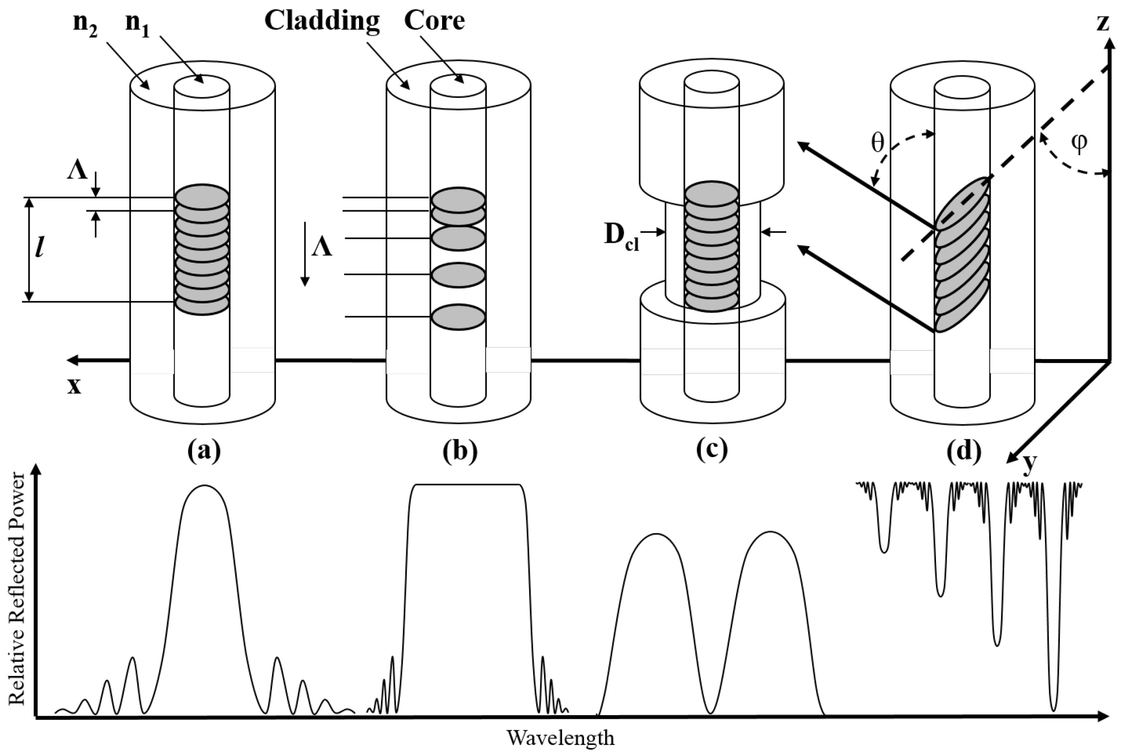
There are essentially three types of gratings which vary in photosensitivity. They are know as type I, II and IIA with the details of each type given in [12]. In addition there are different physical types of gratings such as long period gratings (LPGs), chirped gratings, tilted (blazed) gratings, and micro-structured FBGs. The structure and refractive index profile of some of the different types are shown in Figure 1.
LPGs are similar to standard gratings although they typically have a grating period greater than m. LPGs cause light from the guided mode to be coupled into the cladding modes, where it is lost due to scattering and absorption, resulting in a number of reflected peak wavelengths; a review of LPG sensors is given in [17,18]. Chirped gratings have a varying grating period which usually causes the reflected spectrum to broaden significantly; as such they are often used as bandpass or edge filters [19,20], or interrogators [21]. In tilted gratings, the grating is at an angle with respect to the optical axis causing the light to be coupled outside of the core of the fiber [22]. Generally tilted gratings are used in optical interrogators as spectrometers [23]. The first microstuctured FBG had the cladding diameter reduced around the FBG so that the evanescent wave could interact with the surrounding medium [24,25]. Nowadays, there are many different types of microstrustured fibers with an array of different cross sectional areas which can improve the way the evanescent wave interacts with the medium inside the holes. Examples of some microstructured fibers are shown in Figure 2.
Essentially all of the different types of gratings produce different reflected and/or transmitted spectrum profiles. The profiles can be manipulated and controlled for a given application.
3. Industrial Control Systems and Networking
In industrial applications large arrays of different sensors are typically used forming a distributed sensor network. Where optical fiber sensors are used in process control applications they commonly either convert the optical signal to an electrical signal locally at the sensor, eliminating many of the desired properties of the optical fiber itself as the data is transmitted over copper cables, or use stand alone optical fiber interrogators for data acquisition. Traditional sensor networks use industrial controllers for data acquisition. However, it may be possible to integrate optical fiber sensor networks with standard electronic controllers using a simple optoelectronic interface [26]. A brief description of some of the possible current electronic controllers and networking protocols that may be used in hybrid optical fiber sensor systems is given below. This is by no means a comprehensive or complete list, although it should provide a basis for further discussion regarding some of this issues with respect to integrating optical fiber sensors with current industrial controllers.
3.1. Industrial Controllers
Programmable logic controllers (PLCs) and other industrial automation controllers such as distributed control systems (DCSs) are the standard intelligence for instrumentation and control systems utilised in process control. They are used in a wide variety of industries from car manufacturing to building management systems, as well as controlling machinery in large mine sites [27]. PLCs often form the basis of many automated industrial processes and are essentially the heart of a Supervisory Control And Data Acquisition (SCADA) system. A PLC is an industrial computer specifically designed to be connected to input and output cards in order to take in information from a multitude of sensors in industrial processes, and control actuators in response to those inputs as defined by the control logic [28]. For example, a signal corresponding to the pressure of a fluid in a pipeline may be sent to a PLC which then could send a command to the field to stop a pump, sound an alarm, open a valve, or any other action, depending on what is required. Both PLCs and DCSs were originally developed to replace physical relay systems and designed to fulfill certain criteria:
- Be environmentally rugged ensuring it can operate in an industrial setting;
- Be programmed relatively easily and maintained by plant operators and technicians;
- Be reusable.
Nowadays both PLCs and DCSs can perform much more than basic logic operations and are used to perform complex functions as required by any particular process. PLCs are usually preferred over DCSs for smaller systems where a single PLC may be used to control a specific area of a plant, whereas DCSs are usually used for extremely large processes.
3.2. Embedded Controllers
Embedded controllers such as Raspberry Pi [29] or Arduino microcontrollers [30] are being used more frequently in very small scale control systems. There are educational kits that are used in high school activities, as well as hobby kits for an array of residential applications, such as home automation and robotics. This increase is because the controllers are extremely low cost, small in size and easily programmed using open source software.
3.3. Bus Topologies
Ethernet is one of the most commonly used network protocols that enables communication between computers and other connected devices. With the addition of a router, Ethernet can be used for communication via the internet. The network speed is generally determined by the physical medium used for communication. If fiber optic cables are used bit rates as high as 10Gbit/s are now possible. Industrial processes typically require time specific data transfer, meaning standard Ethernet is not practical as there is no guarantee when the data packet will arrive. However, with the addition of extra protocol layers or by using a master controller Ethernet can be made to be time specific [31].
There are many different bus topologies used in industrial control systems including Modbus, controller area network bus (CANbus), Foundation FieldBus, as well as an array of smaller proprietary protocols. The particular standards used in any one process depend on a number of factors, from the size of the plant to the scale of automation required and the PLC manufacturer. A detailed review of the history of fiedbus technologies is given in [32]. Profibus (process-field-bus) is one of the most widely used industrial protocols. Profibus Decentralised Peripheral (DP) is used for high speed communication between industrial equipment such as large drives. The protocol is based on RS485 and can provide an array of diagnostics about each device on the network, communicating at up to 12 Mbit/s. Profibus Process Automation (PA) is used for monitoring remote sensors. The protocol uses Manchester Bus Powered (MBP) transmission and communicates at a rate of 31.25 kbit/s. Even though it has relatively slow data transmission rates Profibus PA is capable of providing power to sensors using over the same cable used for data transmission [33].
Profinet is a type of industrial Ethernet that incorporates the benefits of Profibus and Ethernet [34]. Profinet offers extremely fast data rates with almost no limitation on the number of slave devices and is also time specific. These attributes mean it is an ideal candidate for communication between a PLC an an optoelectronic interface.
4. Market Overview
4.1. Fiber Optic Sensors
A report released in February 2014 by ElectroniCast, a market and technology forecast consultancy company, states that the global consumption value of FOS will grow from US$1.89 billion in 2013 to US$4.33 billion in 2018 resulting in an annual growth rate of 18% [35]. Whereas a similar report released by BCC Research in June 2014 states the same market will grow from US$1.8 billion in 2013 to US$2.2 billion in 2018, resulting in a compound annual growth rate (CAGR) of 4.5% [36]. This follows BCCs 2011 report which predicted a growth from US$1.2 billion in 2011 to US$2.5 billion in 2017, a CAGR of 10.5% [37]. BCCs latest report released at the beginning of 2017 states that the FOS market will grow from US$2.0 billion in 2016 to US$3.2 billion by 2021 at a CAGR of 9.9% [38]. The latest report by ElectroniCast from May 2017 predicts the FOS market will increase at a CAGR of 7.35% from US$3.38 billion in 2016 to US$4.82 billion in 2021 and then increase at a CAGR of 4.41% to US$5.98 billion by 2026, as shown in Figure 3 [39].
The distributed FOS market was $585 million in 2013 and projected to be US$1.458 billion in 2018 with one of the major applications being process control, as reported by the Photonics Sensor Consortium in conjunction with Light Wave Venture [40]. Despite some discrepancies in the figures all of the reports predict substantial growth in the FOS market, particularly in intrinsic sensors, those embedded within the fiber.
4.2. Automation Industry
The amount of revenue generated from the global process automation market is expected to grow from $86.1 billion in 2012, to $124.3 billion in 2018, at an estimated CAGR of 6.05% from 2013 to 2018. Also, the amount of revenue generated from the process instrumentation market is expected to grow from $26.5 billion in 2012, to $36.7 billion in 2018, with a CAGR of 5.07% [41]. Seamlessly integrating FOS into process control industries has the potential to not only tap into these lucrative markets but also boost them further.
5. Types of Fiber Bragg Grating Sensors for Mainstream Industries
The most commonly used sensors in process control industries such as power generation, water treatment and services, mining, and oil and gas are; temperature, pressure, level, and flow. FBG sensors have been demonstrated sensing each of these different measurands. The following sections should provide the reader with a comprehensive review of the FBG sensors for the those measurands; however, it is by no means a record of every FBG sensor reported to date.
5.1. FBG Temperature Sensors
FBGs are inherently sensitive to temperature as outlined in the theory of this paper, and as such the literature for FBG based temperature sensors is extensive. Some of the key findings will be discussed in this paper and summarised in Table 1. In 1990, Morey et al. [42] were the first to show a FBG temperature sensor. They reported a FBG temperature sensitivity of 6.8 pm/C at a wavelength of 830 nm. Xu et al. [43] reported a FBG temperature sensitivity of 10 pm/C at a wavelength of 1300 nm, in 1994. The following year, Rao et al. [44] reported a FBG temperature sensitivity of 13 pm/C at a wavelength of 1550 nm. Since then Dr Rao has published a number of papers on the progress of FBG technology and applications. Not least, in 1997, Rao et al. [45] devised a FBG temperature sensor system for medical applications. They showed that FBGs could be used for profiling the human body during hyperthermia treatment. They achieved a resolution of 0.1 C and an accuracy of C over a temperature range of 30–60 C. Recently, Mamidi et al. [46] reported a high temperature FBG sensor with an operating range from 20–550 C. Interestingly, they also report a low cost intensity based interrogation technique using a LPG as a linear edge filter. The system had a resolution of 0.5 C. Canning et al. [47] presented a review of 4 different types of temperature sensors using gratings with distinct characteristics. Among these, a high temperature sensor with an operating range of up to 1200 C, was reported.
One of the main applications for FBG based temperature sensors is in electrical power systems and large generators because of their immunity to electromagnetic interference. A number of studies have been performed and are detailed in [48,49,50,51,52,53,54].
Perhaps more significant, with respect to FBG temperature measurements, is the research based on techniques for temperature compensation when using FBGs to detect other measurands. In other words, how is it possible to isolate and distinguish between fluctuations in temperature and strain induced changes. Some of these techniques will be discussed in the following sections.
5.2. FBG Pressure Sensors
Xu et al. [55] reported a FBG pressure sensor in 1993. They showed a wavelength-pressure sensitivity of −3 pm/MPa over a range of 70 MPa. This is the commonly excepted value for the pressure sensitivity of a standard bare FBG. This value is far too low for most sensing applications and as such the main focus of research groups has been to produce pressure sensors with increased sensitivity. The improvements are detailed in the following paragraphs and summarised in Table 2.
Three years later Xu et al. [55] reported their FBG pressure sensor, the same group improved the pressure sensitivity by a factor of ten, using mechanical amplification, by mounting the FBG in a hollow glass bubble [56]. Liu et al. [57] used a polymer coated FBG for simultaneous pressure and temperature measurements. They reported a sensitivity of −80 pm/Mpa and 88 pm/C at 1540.2 nm. By embedding the polymer coated FBG in an aluminium cylinder they later increased the pressure sensitivity of their sensor to −5.28 nm/MPa [58]. A polymer coated FBG embedded in a copper cylinder with improved thermal stability was later reported with a sensitivity of −3.77 nm/MPa at 1558 nm [59]. An ultra thin FBG pressure sensor with the FBG orientated perpendicular to a diaphragm which meant the pressure induced a strain along the length of the FBG was subsequently reported by the same group. The effect of the radius and Young’s modulus of the diaphragm was examined and a maximum sensitivity of 7 nm/MPa was reported [60]. More recently the they reported a diaphragm based FBG sensor which uses an L-shaped lever and has a sensitivity of 0.244 nm/kPa [61].
An FBG pressure sensor embedded within metal bellows was reported by Song et al. [62]. As the metal bellows had a lower spring rate than the fiber, a sensitivity of 48 pm/kPa was reported.
Again using a polymer filled aluminum casing, Ahmad et al. reported a sensitivity of −8.7 nm/MPa [63]. The same group also reported a metal diaphragm based FBG pressure sensor with a sensitivity of −1.67 nm/Mpa [64]. Although this was not as sensitive as the polymer based sensors, it could be used in more practical applications as it was more robust and not susceptible to corrosion.
Likewise, Huang et al. [65] reported a pressure sensor with a sensitivity of 1.57 pm/KPa across a range from 0–1 MPa using a diaphragm with two FBGs bonded to it. This method effectively eliminated the temperature sensitivity of the sensor, as the relative shift in the wavelengths of the two FBGs was used to determine the associated presure. Later a Bourdon tube type FBG pressure sensor designed for pipeline leakage detection was reported by the same group [66]. The sensor had a sensitivity of 1.414 pm/kPa across a range from 0–1 MPa. Temperature compensation was achieved in the same way as their previous sensor.
Pachava et al. also described a diaphragm type FBG pressure sensor where the FBG is bonded perpendicular to the diaphragm surface with a U-shaped clamp. They report a sensitivity of 31.67 nm/MPa [67,68]. Xiong et al. [69] designed, simulated, and tested a similar sensor to that proposed by Pachava et al. which had a sensitivity of 3.55 nm/MPa.
Bock et al. [70] reported a tapered long period Bragg grating pressure sensor with a pressure sensitivity of 51 pm/MPa, which was significantly greater than a bare standard FBG. LPGs have the potential to have custom designed sensitivities, however, the manufacturing process is usually expensive and time consuming. In their paper, Bock et al. describe a new low cost fabrication technique using a computer assisted precision arc-discharge apparatus.
In 2010 and 2011 Yan et al. [71,72] described their pressure sensor sheet which used FBGs fabricated in photonic crystal fibers (PCFs) which were then embedded in polymer foils. Their initial sheet had 5 FBGs within it whereas their later sheet consisted of 15 FBGs in a mesh layout with a spatial resolution of 10mm. The intention was to develop a large area pressure mat for use in rehabilitation and medical fields. They report a local pressure sensitivity of 9.08 pm/kPa and 265 pm/kPa, for the small and large sheet, respectively.
A pressure sensor reported by Hsu et al. [73] has a sensitivity of 28 pm/Mpa and is effectively temperature insensitive. They use a strained FBG and mechanical system that reduces the strain on the FBG as the temperature increases causing the Bragg wavelength to shift in the opposite direction. The result is minimal wavelength shift across a temperature from 10–60 C.
Wu et al. [74] described a sensor capable of measuring temperature and hydrostatic pressure simultaneously using a FBG in a standard section of fiber combined with a FBG in a section of grapefruit microstructured fiber. The FBGs showed a similar response to changes in temperature of approximately 11 pm/C. However, the microstructered FBG was significantly more sensitive to pressure variations having a sensitivity of 13.4 pm/MPa, compared to 4 pm/MPa for the standard FBG.
In 2015 the author’s of this review article developed a highly sensitive standard FBG based pressure sensor. The FBG was bonded to a rubber diaphragm and a sensitivity of 0.116 nm/kPa across a range of 15 kPa was reported [75].
Although this paper reviews FBG sensors in silica fibers, a single reference to a FBG pressure sensor incorporated into a polymer fiber is provided to give context to the improved sensitivity that can be obtained using polymer optical fibers. Rajan et al. [76] reported a pressure sensor incorporating a vinyl diaphragm and a polymer FBG. The lower Young’s modulus of the polymer FBG resulted in a sensitivity of 1.32 pm/Pa, more than 6 times greater than the most sensitive standard FBG pressure sensor reported to date.
5.3. FBG Level Sensors
Many FBG level sensors are essentially pressure sensors that determine the level of a liquid based on the pressure applied by the liquid, which is proportional to the height of the liquid. As such some research groups have developed liquid level sensors through simple modifications of their pressure sensors. Guo et al. [77] described their temperature-insensitive FBG liquid level sensor which was based on a cantilever beam structure. The particular shape of the structure produced a chirp in the FBG under pressure which was proportional to the height of the liquid. This chirp broadened the reflected spectrum and resulted in a change in optical power when connected to a photodiode. Changes in temperature caused the Bragg wavelength to shift but did not change the received optical intensity. This is a good example of exploiting nonlinear responses from an FBG to isolate different measurands. Likewise Sohn et al. [78] described a similar level sensor which had an FBG embedded in it. Lai et al. [79] also reported a liquid level sensor, whereby a FBG was bonded to a cantilever which is attached to a buoy. The FBG experienced a vertical pressure that compresses it depending on the amount of buoyancy, which corresponds to the level of the liquid. Meng et al. [80] reported a similar simple technique using a cantilever with a float attached to the end. As the liquid caused the float to rise, a strain induced wavelength shift occurred. Dai et al. [81] described their simple technique of measuring liquid level by attaching one end of a FBG to the base of a container and the other end to a float, thus relating the strain to the level of the liquid.
In 2002, Fukuchi et al. [82] described a Bourdon tube based water level sensor. An FBG was attached to the end of the Bourdon tube so that an increase in pressure caused by increased water level would increase the strain on the FBF. Sengupta et al. [83] reported a very similar hydrostatic pressure sensor used for measuring liquid level. Their design was also based on a Bourdon tube with two FBGs attached to its free end. The change in hydrostatic pressure induces a strain in one of the FBGs and not the other, meaning it is effectively temperature insensitive. In 2016, Ameen et al. [84] developed a FBG level and temperature sensor which utilised a graphene diaphragm that deformed under hydrostatic pressure. The sensitivity of the sensor reduced as the number of graphene sheets was increased.
There has been some reported techniques for direct liquid level sensing. Khaliq et al. [85] and James et al. [86] described similar LPG level sensors. The ratio of the amount of the FBG immersed in the liquid to that exposed to air produced a change in transmitted intensity. Yun et al. [87] reported an etched FBG liquid level sensor. Etching the cladding from the FBG increases its response to changes in refractive index. Again the ratio of the amount of the FBG immersed in the liquid to that exposed to air produced a change in intensity. Similarly, Mou et al. [88,89,90] demonstrated a semi-immersed FBG that exploited the difference in refractive index of the liquid and air. Their sensor however, used a tilted fiber Bragg grating (TFBG), rather than an etched FBG or a LPG. Recently Gu et al. [91] demonstrated a similar technique using a TFBG inscribed in a thin core section of a fiber. Their results show high sensitivity and immunity to temperature changes.
5.4. FBG Flow Sensors
Recently, there have been a number of studies performed using FBGs as flow sensors. As with all FBG transducers, FBG flow sensors either manipulate strain or temperature induced wavelength shift to determine the flow rate. Some research groups, such as Zhan et al. [92], have developed flow sensors that act in a similar way to the level sensors, in that a cantilever is used as the basis of the sensor. The force created by the flow of a fluid causes the cantilever to deflect which in turn changes the induces a strain on the FBG. Lu and Chen [93] also used this technique and reported a flow meter with a resolution of 58.1 cm/s in the forward direction and 166 cm/s in the backward direction. Yao et al. [94] also used this method although they used two FBGs, one attached to either side of the cantilever for temperature compensation. Other gas flow sensors exploit the changes in temperature, by coating the FBG and adapting the principles of conventional hot-wire-anemometers. That is, monitoring the temperature change as a function of gas flow around the sensor [95]. Cashdollar and Chen [96], and Caldas et al. [97,98] reported a gas flow meter using this technique, by coating a FBG with silver. Chashdollar and Chen [96] demonstrated a FBG heated with a laser diode and nitrogen gas blown on to it. The results showed that the change in temperature of the FBG , and hence the shift in Bragg wavelength, related to the gas flow rate. Caldas et al. [97,98] used a hybrid LPG and FBG setup with 1480 nm light launched into the fiber. They presented a working air flow meter with a resolution of 0.8 m/s.
Rodriguez-Cobo et al. [99] proposed a novel FBG flow sensor. They demonstrated an arc-shaped plastic flow transducer with two FBG attached to it. The air flow caused one FBG to stretch and the other to compress. Salgado et al. [100] use two strain sensor FBGs to measure the change in circumference and length of a PVC pipe which they correlated with the flow rate of the fluid in the pipe. Jiang and Gao [101] report a dual FBG flow sensor using an elastomer transducer with a specifically designed shape to maximize the impact of the fluid flow.
Zamarreno et al. [102] demonstrated a multiplexed 8 × 8 FBG array for measuring flow rate, followed by a 16 × 16 FBG array capable of measuring fluid turbulence [103]. The FBG array was orientated perpendicular to the pipe, producing a two dimensional map of the fluid flow. The results showed different patterns for different flow rates.
5.5. Additional FBG Sensors
Over the years there have been a many papers published on the use of FBGs as chemical sensors, from Meltz et al. [104] in 1991 to Lu et al. [105] in 2009. Most techniques are based on the interaction of hydrogels or polymers that swell in the presence of specific chemicals or the interaction of the evanescent field with different chemicals. When an FBG is immersed in a hydrogel it causes the FBG to expand as the hydrogel swells [106]. Cong et al. [107] specifically show a salinity sensor using this method. Frazao et al [108] reported an etched FBG for salinity measurement through evanescent field interaction. Furthermore, the group demonstrated the use of their sensor for simultaneous measurement of salinity and temperature in a large scale, fully integrated, environmental monitoring system.
FBGs have become the basis of a number of more exotic sensors such as magnetic field sensors, accelerometers, and tilt sensors, etc. An example of some of these sensors is given below. Madhav et al. [109] demonstrated that a FBG bonded to a piece of nickel can act as a magnetic field sensor. A magnetic field induces a strain on the nickel which is detected by the FBG. Zhu and Shum [110] report a FBG accelerometer in which a FBG attached to a cantilever is deflected depending on the magnitude of the applied acceleration. Guan et al. [111] describe a FBG tilt sensor. Four FBG sensors are attached to four arms that are perpendicular to a pendulum. Each FBG is strained equally when the pendulum is vertical; when the pendulum is tilted each FBG experiences a strain. The system can detect the magnitude and direction of the inclination with respect to the horizontal direction.
6. FBG Multiplexing and Interrogation Techniques
One of the main advantages of FBG sensors is their ability to be easily multiplexed through time division multiplexing (TDM) and wavelength division multiplexing (WDM). There are many different multiplexing architectures for quasi distributed sensor systems such as serial bus, dual bus, star, tree and mesh. Each of these architectures are detailed in [112]. Which architecture is the most appropriate depends on the requirements of the application, such as the number of sensors in a system, and also on cost.
The information from each sensor must be separated and interpreted, which requires an interrogator system to interrogate many FBGs connected in series. Initially, FBG interrogators were large, complex and expensive units, however, since the late nineties, a number of different groups have attempted to minimise and simplify them without loss of functionality.
In 1998, Fallen et al. [113] report a simple passive system that can simultaneously interrogate several FBG sensors. Half of the reflected light is incident on a ramped grating and the other half is sent to a reference arm. As the ramped grating has a large bandwidth, each reflected signal from multiple FBGs in series would be reflected off different parts of the ramped FBG.
In a similar way, Chtcherbakov et al. [21] present an active interrogation system using a chirped FBG. However, instead of receiving a change in intensity, the signal is converted into a phase change and de-multiplexed using an arrayed-waveguide grating; then the signals are sent to separate detectors.
Ye et al. [114] demonstrate an active interrogation method using polarisation maintaining (PM) fibers, whereby the reflected signals from multiple FBGs firstly pass through a Fabry-Perot filter, separating the different wavelengths, and secondly, pass through a polarisation splitter, which are then sent to two different detectors. The advantages associated with this method are such that the transverse strain measurements are inherently temperature independent, and as there are two separate detectors, there is no limitation on the measurable strain due to the gap between the two Bragg wavelengths decreasing below the normal achievable resolution.
Another active interrogation system shown by Abad et al. [115] uses a two stage de-modulation similar to that of Ye et al. [114], except they use a LPG rather than a chirped grating for separating the wavelengths and then phase delay the signals using a delay line. This method only requires the use of a single detector as the relative phase difference is not affected by unwanted power fluctuations.
A portable, robust FBG interrogation system was proposed by Roths et al. [116] in 2005. The technique uses a tunable FBG that is stretched by a piezo-electric transducer (PZT) and a saw-tooth voltage signal, which acts as an analyser. This approach has significant merit, as it addresses the issue of reducing the complexity and cost associated with interrogator systems. Unfortunately, the system requires fairly extensive calibration and data acquisition software to correct non-linearities associated with the PZT.
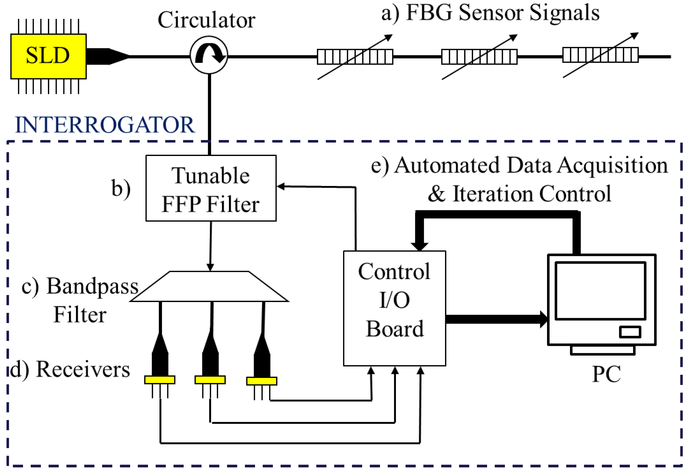
Beccherelli et al. [117] report an intensity based interrogation method using an integrated optical filter. Here they use a tunable liquid crystal polymer that can select a specific wavelength depending on the voltage. Again, they present their work as a simple inexpensive option. Likewise, Tsai et al. [118] use an intensity based tunable system incorporating a fiber Fabry-Perot (FFP) filter that is controlled by a voltage from a control I/O board. The FFP filter is tuned with an incremental step of 0.02 V, which corresponds to a resolution of 5 pm in wavelength. The network architecture is shown in Figure 4.
Orr and Niewczas [119] report a polarization-switching FBG interrogator for simultaneous measurement of magnetic field strength and temperature. The system uses a polarisation beam splitter and a fast optical switch to select which polarised signal is sent to the Mach-Zehnder interferometer. The interrogation involves comparing reflections from both left and right circularly polarised light. In this way, any common noise or drift can be easily cancelled out. As the magnetic field strength is determined from the angle of polarisation, any other measurand that causes a wavelength shift, i.e., temperature, pressure, etc., can be measured simultaneously. While this active technique appears to be effective, the setup is expensive because of its complexity.
Due to the increase in use of FBG networks over the last decade, a number of different commercial interrogator systems have emerged [120]. However, the technology is still relatively new, meaning many of the products on the market do not live up to the manufacturer’s claims or customer’s expectations, for a number of different reasons including system failure and inaccurate measurements. Furthermore, the lack of a robust measuring system is not only due to problems associated with the interrogator itself, but also with the interrogator software and the complexity of the sensors . In addition, it is worth noting that all of the commercial interrogators available are large expensive units. A detailed comparison of the performance of the HBM, Insensys, and Smart Fibres products is given in [120].
7. Optical Actuation and All Optical Control Systems
An entirely optical control system would be highly advantageous in certain applications. They have the potential to exceed current sensitivity and communication speeds as well as having all the advantages associated with optical systems and none of the drawbacks of electrical systems.
The goal is to create a control loop where the process variable is both detected and modulated in the optical domain, in addition to the controller providing feedback optically, with the final component being actuated via an opto-pneumatic or opto-electric converter. While steps have been made toward achieving this goal, to date a practical complete system has not been realised and currently the best solution is to have minimal electronic signal conversion.
In 1990, Hockaday and Waters [121] demonstrated a technique for direct optical to mechanical actuation. Their method uses lasers to heat a pneumatic or hydraulic fluid causing it to deviate from a central path. The deflection was a result of optical modulation of the fluid viscosity. The deflected jet of fluid produced a direct differential pressure signal that can be controlled without the need of any electronic signal. The differential pressure was used to actuate a valve.
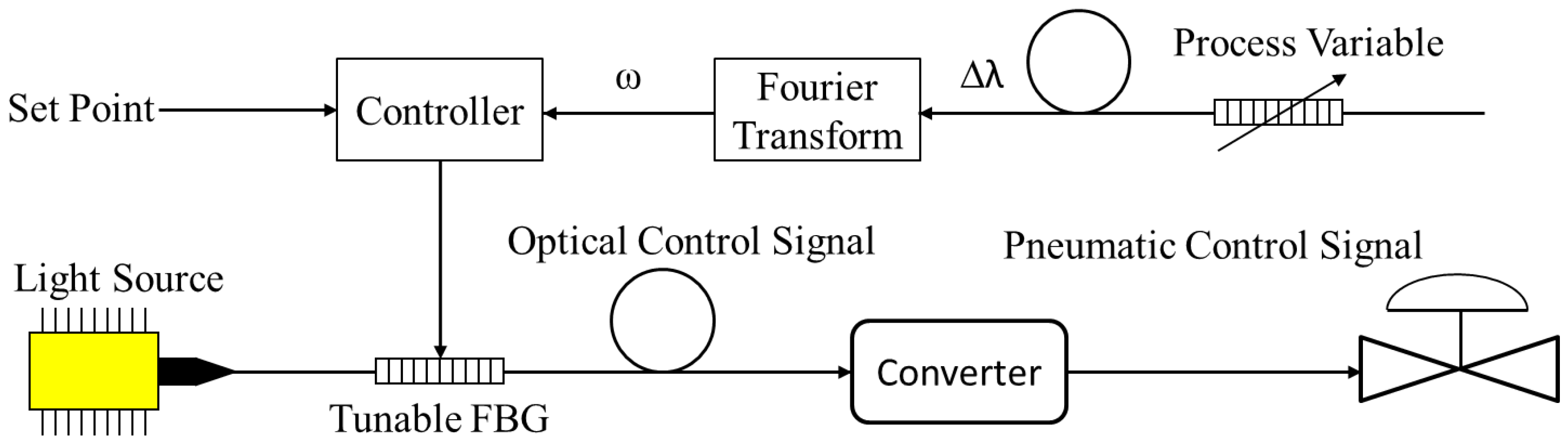
In 2003, Mohamed Mahmoud [122] discussed the potential of an all optical control system (AOCS) incorporating FBGs. FBGs enable the process variable to be transmitted, modulated, and received on a single fiber optic cable and “mimics the two wire 4–20 mA electronic signal of an electronic process control loop”. He describes how FBGs can be used to measure many different process variables such as temperature, strain, and flow, and illustrates an AOCS shown in Figure 5, where the process variable is converted into a frequency via a fast Fourier transform, and then the controller uses a PZT to tune another FBG to provide an optical output. It is stated that the proposed system would need an opto-pneumatic or opto-electric converter to provide actuation. The actuation could then be performed by a technique based on Hockaday and Waters system [121] or by using a photovoltaic power converter [123].
Photovoltaic power converters (PPCs) are essentially miniature solar cells designed to be responsive to specific wavelengths and connected directly to an optical fiber. GaAs photovoltaic power converters have conversion efficiencies as high as 55% [124] and can produce up to 0.5 W of electrical power. Although only GaAs based PPCs are commercially manufactured, research has shown that both Silicon and Germanium PPCs could be a viable solution for longer wavelength power conversion, having optical to electrical power conversion efficiencies as high as 50% [123]. Furthermore, it has been demonstrated that communication, sensing and power signals can be simultaneously sent over the same fiber without any interference or loss of signal strengths [125].
8. Interfacing and Networking FBGs
Ping et al. [126,127] report a networked FOS system based on the IEEE1451 standard for smart transducer interfaces for sensors and actuators. In their study, a GaAs chip is used as a temperature sensor and connected to a smart transducer interface module (STIM). The STIM is then connected to a PC or PLC, which acts as a virtual network capable application processor (NCAP), via a CAN bus interface module.
While the work performed by Kunzler et al. [128,129] is predominantly based on their FBG interrogation technique, their FSIM acts as a smart sensor node, having additional functionality such as signal conditioning, data processing, and a bus output locally on-board. Hence, the FSIM is connected to a network of other devices using Ethernet.
9. The Future of FBG Sensing in Industry
In order for FOS networks to penetrate into mainstream industrial processes two things must happen. Firstly, appropriate transducers must be developed that satisfy a number of criteria:
- Be environmentally rugged;
- Have appropriate sensitivity;
- Have the correct dynamic range;
- Be easily replaceable without disrupting the network;
- Adhere to engineering standards, either existing or new.
Secondly, FOS networks should be seamlessly integrated with existing control system architectures. Standalone FOS interrogators are expensive and require knowledge of optical engineering. FOS have the potential to replace all of the downstream I/O components from a PLC or DCS in certain applications. However, in the interim, integrating an array of fiber sensors into an existing control system would be a logical first step. A fiber system could be connected to a PLC through a simple interface module such that the PLC and operators perceive the FOS as standard electronic sensors. This would eliminate the need for additional training and therefore reduce costs and would allow confidence in optical fiber sensing to build up, enabling the use of fiber sensors to become standard engineering practice in mainstream industrial processes. Further, this would pave the way for almost entirely optical control systems of the future.
In addition, interfacing FOS with low cost embedded controllers may have the potential to form smart hybrid systems such as those containing wireless sensor networks and FOS networks. Moreover, the information from the FOS could be sent over a wireless network as proposed in [130].
10. Conclusions
In conclusion, a review of FBG sensing technology with respect to their use in mainstream industrial process applications has been performed. The review has focused on the types of sensors that have been developed for industries such as power generation, water treatment and services, mining, and the oil and gas sector. A market overview was reported, as well as a discussion of some of the factors limiting their penetration into these markets. Furthermore, the author has made recommendations for future work that would potentially provide significant opportunity for the advancement of FBG sensor networks in these mainstream industries.
Acknowledgments
We would like to thank ElectroniCast consultants for providing current market forecast data. No funds were received for covering the costs to publish in open access.
Author Contributions
All author’s contributed equally to content of this review article.
Conflicts of Interest
The authors declare no conflict of interest.
References
- Willsch, R.; Ecke, W.; Schwotzer, G. Spectrally encoded optical fibre sensor systems and their application in process control, environmental and structural monitoring. In Proceedings of the SPIE Congress on Optics and Optoelectronics, Warsaw, Poland, 28 August–2 September 2005; p. 59520I. [Google Scholar]
- Willsch, R.; Ecke, W.; Bartelt, H. Optical fiber sensor research and industry in Germany: Review and outlook. In Proceedings of the SPIE 21st International Conference on Optical Fibre Sensors, Ottawa, ON, Canada, 15–19 May 2011; p. 775302. [Google Scholar]
- Culshaw, B.; Kersey, A. Fiber-optic sensing: A historical perspective. J. Lightwave Technol. 2008, 26, 1064–1078. [Google Scholar] [CrossRef]
- Culshaw, B. Fibre optics in sensing and measurement-achievements and opportunities. In Proceedings of the 2nd International Conference on Opto-Electronics and Applied Optics (IEM OPTRONIX), Vancouver, BC, Canada, 15–17 October 2015; pp. 1–5. [Google Scholar]
- Kersey, A.D.; Davis, M.A.; Patrick, H.J.; LeBlanc, M.; Koo, K.P.; Askins, C.G.; Putnam, M.A.; Friebele, E.J. Fiber grating sensors. J. Lightwave Technol. 1997, 15, 1442–1462. [Google Scholar] [CrossRef]
- Kinet, D.; Mégret, P.; Goossen, K.W.; Qiu, L.; Heider, D.; Caucheteur, C. Fiber Bragg grating sensors toward structural health monitoring in composite materials: challenges and solutions. Sensors 2014, 14, 7394–7419. [Google Scholar] [CrossRef] [PubMed]
- Kahandawa, G.C.; Epaarachchi, J.; Wang, H.; Lau, K. Use of FBG sensors for SHM in aerospace structures. Photonic Sens. 2012, 2, 203–214. [Google Scholar] [CrossRef] [Green Version]
- Catalano, A.; Bruno, F.A.; Galliano, C.; Pisco, M.; Persiano, G.V.; Cutolo, A.; Cusano, A. An optical fiber intrusion detection system for railway security. Sens. Actuators A Phys. 2017, 253, 91–100. [Google Scholar] [CrossRef]
- Wild, G.; Hinckley, S. Acousto-ultrasonic optical fiber sensors: overview and state-of-the-art. IEEE Sens. J. 2008, 8, 1184–1193. [Google Scholar] [CrossRef]
- Allwood, G.; Wild, G.; Hinckley, S. Optical fiber sensors in physical intrusion detection systems: A review. IEEE Sens. J. 2016, 16, 5497–5509. [Google Scholar] [CrossRef]
- Qiao, X.; Shao, Z.; Bao, W.; Rong, Q. Fiber Bragg Grating Sensors for the Oil Industry. Sensors 2017, 17, 429. [Google Scholar] [CrossRef] [PubMed]
- Kashyup, R. Fiber Bragg Gratings; Academic Press: San Diego, CA, USA, 1999. [Google Scholar]
- Lefebvre, P.; Vincelette, A.; Beaulieu, C.; Ficocelli, P. Automated manufacturing of fiber Bragg grating arrays. In Proceedings of the OSA Optical Fiber Sensors, Cancun, Mexico, 23–27 October 2006; p. ThE27. [Google Scholar]
- Marques, C.; Drummond, M.; Conradin, F.; Nogueira, R. Implementation of an automated fiber Bragg grating writing system. In Proceedings of the Conference On Telecommunications-ConfTele, Vila da Feira, Portugal, 9 May 2009; p. 399Y402. [Google Scholar]
- Peters, K. Polymer optical fiber sensors—A review. Smart Mater. Struct. 2010, 20, 013002. [Google Scholar] [CrossRef]
- Othonos, A.; Kalli, K. Fiber Bragg Grating Fundamentals and Applications in Telecommunications and Sensing; Artech House: Boston, MA, USA, 1999. [Google Scholar]
- James, S.W.; Tatam, R.P. Optical fibre long-period grating sensors: Characteristics and application. Meas. Sci. Technol. 2003, 14, R49–R61. [Google Scholar] [CrossRef]
- Webb, D.J.; Allsop, T.; Dobb, H.; Kalli, K.; Earthrowl, T.; Mezentsev, V.; Gillooly, A.; Neal, R.; Bennion, I. Sensing applications of long-period gratings in various fibre types. In Proceedings of the SPIE Second European Workshop on Optical Fibre Sensors, Santander, Spain, 9–11 June 2004; pp. 104–107. [Google Scholar]
- Bandyopadhyay, S.; Biswas, P.; Pal, A.; Bhadra, S.K.; Dasgupta, K. Empirical relations for design of linear edge filters using apodized linearly chirped fiber Bragg grating. J. Lightwave Technol. 2008, 26, 3853–3859. [Google Scholar] [CrossRef]
- Wu, Q.; Farrell, G.; Semenova, Y. Simple design technique for a triangular FBG filter based on a linearly chirped grating. Opt. Commun. 2010, 283, 985–992. [Google Scholar] [CrossRef]
- Chtcherbakov, A.A.; Swart, P.L. Chirped fiber-optic Bragg grating interrogator in a multiplexed Bragg grating sensor configuration. J. Lightwave Technol. 2004, 22, 1543–1547. [Google Scholar] [CrossRef]
- Zhao, Y.; Wang, Q.; Huang, H. Characteristics and applications of tilted fiber Bragg gratings. J. Optoelectron. Adv. Mater. 2010, 12, 2343–2354. [Google Scholar]
- Suo, R.; Chen, X.; Zhou, K.; Zhang, L.; Bennion, I. 800 nm WDM interrogation system for strain, temperature, and refractive index sensing based on tilted fiber Bragg grating. IEEE Sens. J. 2008, 8, 1273–1279. [Google Scholar] [CrossRef]
- Iadicicco, A.; Campopiano, S.; Cutolo, A.; Giordano, M.; Cusano, A. Microstructured fibre Bragg gratings: Analysis and fabrication. Electron Lett. 2005, 41, 466–468. [Google Scholar] [CrossRef]
- Cusano, A.; Iadicicco, A.; Paladino, D.; Campopiano, S.; Cutolo, A.; Giordano, M. Micro-structured fiber Bragg gratings. Part I: Spectral characteristics. Opt. Fiber Technol. 2007, 13, 281–290. [Google Scholar] [CrossRef]
- Allwood, G.; Wild, G.; Hinckley, S. Programmable logic controller optical fibre sensor interface module. SPIE Smart Nano + Micro Materials and Devices. In Proceedings of the Smart Nano-Micro Materials and Devices, Melbourne, Australia, 4–7 December 2011. [Google Scholar]
- Kouthon, T.; Decotignie, J.D. Improving time performances of distributed PLC applications. In Proceedings of the IEEE Emerging Technologies and Factory Automation, Kauai, HI, USA, 18–21 November 1996; Volume 2, pp. 656–662. [Google Scholar]
- Bolton, W. Programmable Logic Controllers; Newnes (Elsevier): Oxford, UK, 2009. [Google Scholar]
- Upton, E.; Halfacree, G. Raspberry Pi User Guide; John Wiley & Sons: Hoboken, NJ, USA, 2013. [Google Scholar]
- Sarik, J.; Kymissis, I. Lab kits using the Arduino prototyping platform. In Proceedings of the IEEE Frontiers in Education Conference, Arlington, VA, USA, 27–30 October 2010; p. T3C-1. [Google Scholar]
- Axelson, J. Embedded ETHERNET and Internet Complete; Lakeview Research: Madison, WI, USA, 2003. [Google Scholar]
- Thomesse, J.P. Fieldbus technology in industrial automation. Proc. IEEE 2005, 93, 1073–1101. [Google Scholar] [CrossRef]
- Belai, I.; Drahoš, P. The industrial communication systems Profibus and PROFInet. Appl. Nat. Sci. 2009, 329–336. [Google Scholar]
- Neumann, P.; Poschmann, A. Ethernet-based real-time communications with PROFINET IO. WSEAS Trans. Commun. 2005, 4, 235–245. [Google Scholar]
- ElectroniCast. Fiber Optic Sensors Global Market Forecast & Analysis; Technical Report; EletroniCast Consultants: Aptos, CA, USA, 2014. [Google Scholar]
- Research, B. Fiber Optic Sensors: Global Markets; Technical Report; BCC Research LLC: Wellesley, MA, USA, 2014. [Google Scholar]
- Research, B. Fiber Optic Sensors: Global Markets; Technical Report; BCC Research LLC: Wellesley, MA, USA, 2011. [Google Scholar]
- Research, B. Fiber Optic Sensors: Global Markets; Technical Report; BCC Research LLC: Wellesley, MA, USA, 2017. [Google Scholar]
- ElectroniCast. Fiber Optic Sensors Global Market Forecast & Analysis; Technical Report; EletroniCast Consultants: Aptos, CA, USA, 2017. [Google Scholar]
- 2014 Photonic Sensor Consortium Market Survey Report. Available online: http://www.sensorsmag.com/components/2014-photonic-sensor-market-report. (accessed on 27 October 2017).
- MarketsandMarkets. Process Automation Market & Instrumentation Market—By Technology (SCADA, PLC, DCS, MES), Communication (Profibus, Fieldbus, Wireless HART, ISA100), Transmitter (Flow, Temperature, Level, Pressure) —Analysis and Forecast (2013–2018); Technical Report; MarketsandMarkets: Pune, India, 2013. [Google Scholar]
- Morey, W.W.; Meltz, G.; Glenn, W.H. Fiber optic Bragg grating sensors. In Proceedings of the SPIE Fiber Optic and Laser Sensors VII, Boston, MA, USA, 5–7 September 1989; Volume 1169, pp. 98–107. [Google Scholar]
- Xu, M.; Archambault, J.L.; Reekie, L.; Dakin, J. Discrimination between strain and temperature effects using dual-wavelength fibre grating sensors. Electron. Lett. 1994, 30, 1085–1087. [Google Scholar] [CrossRef]
- Rao, Y.; Zhang, L.; Bennion, I.; Lobo Ribeiro, A.; Jackson, D. Combined spatial-and time-division-multiplexing scheme for fiber grating sensors with drift-compensated phase-sensitive detection. Opt. Lett. 1995, 20, 2149–2151. [Google Scholar] [CrossRef] [PubMed]
- Rao, Y.J.; Webb, D.J.; Jackson, D.A.; Zhang, L.; Bennion, I. In-fiber Bragg-grating temperature sensor system for medical applications. J. Lightwave Technol. 1997, 15, 779–785. [Google Scholar]
- Mamidi, V.R.; Kamineni, S.; Ravinuthala, L.S.P.; Madhuvarasu, S.S.; Thumu, V.R.; Pachava, V.R.; Putha, K. Fiber Bragg grating-based high temperature sensor and its low cost interrogation system with enhanced resolution. Opt. Appl. 2014, 44. [Google Scholar]
- Canning, J.; Stevenson, M.; Cook, K.; Aslund, M.; Ecke, W.; Willsch, R.; Bartelt, H.; Kalinowski, H.; Grabarski, L.; Oliveira, V.; et al. Optical fibre Bragg gratings for high temperature sensing. In Proceedings of the 20th International Conference on Optical Fibre Sensors, Scotland, UK, 5–9 October 2009; p. 75032N. [Google Scholar]
- Romero, M.A.; Calligaris, A., Jr.; Silva, M.T.C. A fiber-optic Bragg-grating temperature sensor for high-voltage transmission lines. In Proceedings of the IEEE Microwave and Optoelectronics Conference: Linking to the Next Century, Natal, Brazil, 11–14 August 1997; Volume 1, pp. 34–38. [Google Scholar]
- Lee, H.; Jin, Z.; Song, M. Investigation of fiber Bragg grating temperature sensors for applications in electric power systems. In Proceedings of the 8th International IEEE Conference on Properties & Applications of Dielectric Materials (ICPADM), Bali, Indonesia, 26–30 June 2006; pp. 579–584. [Google Scholar]
- Kim, M.; Lee, J.H.; Koo, J.Y.; Song, M. A study on internal temperature monitoring system for power transformer using pptical Fiber Bragg Grating sensors. In Proceedings of the IEEE International Symposium on Electrical Insulating Materials, Yokkaichi, Japan, 7–11 September 2008; pp. 163–166. [Google Scholar]
- Cheng, Y.; Tian, X.; Jiang, J.; Li, C. Using Fiber Bragg grating sensor on ice monitoring on electric power transmission lines, part I: The measurement of the temperature. In Proceedings of the IEEE High Voltage Engineering and Application, New Orleans, LA, USA, 11–14 October 2010; pp. 256–259. [Google Scholar]
- Wang, P.; Liu, J.; Song, F.; Zhao, H. Quasi-distributed temperature measurement for stator bars in large generator via use of Fiber Bragg Gratings. In Proceedings of the 6th International Forum on Strategic Technology, Harbin, China, 22–24 August 2011; Volume 2, pp. 810–813. [Google Scholar]
- De Morais Sousa, K.; Hafner, A.; Crespim, M.; Somenzi, J.; de Oliveira, V.; Kalinowski, H.; da Silva, J. Fiber Bragg grating sensing applications in temperature monitoring of three-phase induction motors. In Proceedings of the IEEE Microwave & Optoelectronics Conferencel, Natal, Brazil, 29 October–1 November 2011; pp. 862–866. [Google Scholar]
- Werneck, M.M.; Allil, R.C.d.S.B.; Ribeiro, B.A. Calibration and operation of a fibre Bragg grating temperature sensing system in a grid-connected hydrogenerator. Sci. Meas. Technol. 2013, 7, 59–68. [Google Scholar] [CrossRef]
- Xu, M.; Reekie, L.; Chow, Y.; Dakin, J.P. Optical in-fibre grating high pressure sensor. Electron. Lett. 1993, 29, 398–399. [Google Scholar] [CrossRef]
- Xu, M.; Geiger, H.; Dakin, J. Fibre grating pressure sensor with enhanced sensitivity using a glass-bubble housing. Electron. Lett. 1996, 32, 128–129. [Google Scholar] [CrossRef]
- Liu, Y.; Guo, Z.; Zhang, Y.; Chiang, K.S.; Dong, X. Simultaneous pressure and temperature measurement with polymer-coated fibre Bragg grating. Electron. Lett. 2000, 36, 564–566. [Google Scholar] [CrossRef]
- Zhang, Y.; Feng, D.; Liu, Z.; Guo, Z.; Dong, X.; Chiang, K.S.; Chu, B.C. High-sensitivity pressure sensor using a shielded polymer-coated fiber Bragg grating. IEEE Photonics Technol. Lett. 2001, 13, 618–619. [Google Scholar] [CrossRef]
- Liu, L.; Zhang, H.; Zhao, Q.; Liu, Y.; Li, F. Temperature-independent FBG pressure sensor with high sensitivity. Opt. Fiber Technol. 2007, 13, 78–80. [Google Scholar] [CrossRef]
- Zhang, W.; Li, F.; Liu, Y.; Liu, L. Ultrathin FBG pressure sensor with enhanced responsivity. Photonics Technol. Lett. 2007, 19, 1553–1555. [Google Scholar] [CrossRef]
- Zhang, W.; Li, F.; Liu, Y. Fiber Bragg grating pressure sensor with ultrahigh sensitivity and reduced temperature sensitivity. Opt. Eng. 2009, 48, 024402. [Google Scholar] [CrossRef]
- Song, D.; Zou, J.; Wei, Z.; Yang, S.; Cui, H. High-sensitivity pressure sensor based on fiber Bragg grating and metal bellows. In Proceedings of the SPIE Defense, Security, and Sensing, Orlando, FL, USA, 13 – 17 April 2009; Volume 7316. Article 73160H-1. [Google Scholar]
- Ahmad, H.; Harun, S.; Chong, W.; Zulkifli, M.; Thant, M.; Yusof, Z.; Poopalan, P. High-sensitivity pressure sensor using a polymer-embedded FBG. Microw. Opt. Technol. Lett. 2008, 50, 60–61. [Google Scholar] [CrossRef]
- Ahmad, H.; Chong, W.Y.; Thambiratnam, K.; Zulklifi, M.Z.; Poopalan, P.; Thant, M.M.M.; Harun, S.W. High sensitivity fiber Bragg grating pressure sensor using thin metal diaphragm. IEEE Sens. J. 2009, 9, 1654–1659. [Google Scholar] [CrossRef]
- Huang, J.; Zhou, Z.; Wen, X.; Zhang, D. A diaphragm-type fiber Bragg grating pressure sensor with temperature compensation. Measurement 2013, 46, 1041–1046. [Google Scholar] [CrossRef]
- Huang, J.; Zhou, Z.; Zhang, D.; Wei, Q. A fiber Bragg grating pressure sensor and its application to pipeline leakage detection. Adv. Mech. Eng. 2013, 2013. [Google Scholar] [CrossRef]
- Pachava, V.R.; Kamineni, S.; Madhuvarasu, S.S.; Putha, K. Enhanced sensitivity of FBG pressure sensor using thin metal diaphragm. In Proceedings of the OSA International Conference on Fibre Optics and Photonics, Chennai, India, 9–12 December 2012; p. TPo-20. [Google Scholar]
- Pachava, V.R.; Kamineni, S.; Madhuvarasu, S.S.; Putha, K. A high sensitive FBG pressure sensor using thin metal diaphragm. J. Opt. 2014, 43, 117–121. [Google Scholar] [CrossRef]
- Xiong, Y.; He, J.; Yang, W.; Sheng, L.; Gao, W.; Chen, Y. Research on FBG pressure sensor of flat diaphragm structure. In Proceedings of the International Conference on Measurement, Information and Control (MIC), Harbin, China, 18–20 May 2012; pp. 787–790. [Google Scholar]
- Bock, W.J.; Chen, J.; Mikulic, P.; Eftimov, T. A novel fiber-optic tapered long-period grating sensor for pressure monitoring. Trans. Instrum. Meas. 2007, 56, 1176–1180. [Google Scholar] [CrossRef]
- Yan, C.; Ferraris, E.; Geernaert, T.; Berghmans, F.; Reynaerts, D. Development of flexible pressure sensing polymer foils based on embedded fibre Bragg grating sensors. Proced. Eng. 2010, 5, 272–275. [Google Scholar] [CrossRef]
- Yan, C.; Ferraris, E.; Reynaerts, D. A pressure sensing sheet based on optical fibre technology. Procedia Eng. 2011, 25, 495–498. [Google Scholar] [CrossRef]
- Hsu, Y.; Wang, L.; Liu, W.F.; Chiang, Y. Temperature compensation of optical fiber Bragg grating pressure sensor. Photonics Technol. Lett. 2006, 18, 874–876. [Google Scholar] [CrossRef]
- Wu, H.; Rao, Y.; Li, S.; Lu, X.; Wu, Y. A novel FBG-based fence with high sensitivity and low nuisance alarm rate. In Proceedings of the 21st International Conference on Optical Fibre Sensors (OFS21), Ottawa, ON, Canada, 15–19 May 2011; p. 77537R. [Google Scholar]
- Allwood, G.; Wild, G.; Lubansky, A.; Hinckley, S. A highly sensitive fiber Bragg grating diaphragm pressure transducer. Opt. Fiber Technol. 2015, 25, 25–32. [Google Scholar] [CrossRef]
- Rajan, G.; Liu, B.; Luo, Y.; Ambikairajah, E.; Peng, G.D. High sensitivity force and pressure measurements using etched singlemode polymer fiber Bragg gratings. IEEE Sens. J. 2013, 13, 1794–1800. [Google Scholar] [CrossRef]
- Guo, T.; Zhao, Q.; Dou, Q.; Zhang, H.; Xue, L.; Huang, G.; Dong, X. Temperature-insensitive fiber Bragg grating liquid-level sensor based on bending cantilever beam. Photonics Technol. Lett. 2005, 17, 2400–2402. [Google Scholar]
- Sohn, K.R.; Shim, J.H. Liquid-level monitoring sensor systems using fiber Bragg grating embedded in cantilever. Sens. Actuators A Phys. 2009, 152, 248–251. [Google Scholar] [CrossRef]
- Lai, C.W.; Lo, Y.L.; Yur, J.P.; Chuang, C.H. Application of fiber Bragg grating level sensor and Fabry-Perot pressure sensor to simultaneous measurement of liquid level and specific gravity. IEEE Sens. J. 2012, 12, 827–831. [Google Scholar] [CrossRef]
- Meng, L.; Liu, Y.; Wang, T. A novel liquid level monitoring sensor system using a fiber Bragg grating. In Proceedings of the IET International Conference on Smart and Sustainable City, Shanghai, China, 19–20 August 2013; pp. 145–148. [Google Scholar]
- Dai, Y.; Sun, Q.; Wo, J.; Li, X.; Zhang, M.; Liu, D. Highly sensitive liquid-level sensor based on weak uniform fiber Bragg grating with narrow-bandwidth. Opt. Eng. 2012, 51, 044401. [Google Scholar] [CrossRef]
- Fukuchi, K.; Kojima, S.; Hishida, Y.; Hongo, A. Optical water-level sensing systems using fiber Bragg grating. In Proceedings of the SPIE Photonics Asia, Shanghai, China, 13 September 2002; pp. 54–61. [Google Scholar]
- Sengupta, D.; Shankar, M.S.; Rao, P.V.; Reddy, P.S.; Prasad, R.S.; Kishore, P.; Srimannarayana, K. Temperature compensated liquid level sensor using FBGs and a bourdon tube. Proceedings of SPIE Asia Communications and Photonics, Shanghai, China, 13–16 November 2011; p. 83110R. [Google Scholar]
- Ameen, O.F.; Younus, M.H.; Aziz, M.; Azmi, A.I.; Ibrahim, R.R.; Ghoshal, S. Graphene diaphragm integrated FBG sensors for simultaneous measurement of water level and temperature. Sens. Actuators A Phys. 2016, 252, 225–232. [Google Scholar] [CrossRef]
- Khaliq, S.; James, S.W.; Tatam, R.P. Fiber-optic liquid-level sensor using a long-period grating. Opt. Lett. 2001, 26, 1224–1226. [Google Scholar] [CrossRef] [PubMed]
- James, S.W.; Khaliq, S.; Tatam, R.P. A long period grating liquid level sensor. In Proceedings of the 15th Optical Fiber Sensors Conference Technical Diges, Portland, OR, USA, 6–10 May 2002; pp. 127–130. [Google Scholar]
- Yun, B.; Chen, N.; Cui, Y. Highly sensitive liquid-level sensor based on etched fiber Bragg grating. Photonics Technol. Lett. 2007, 19, 1747–1749. [Google Scholar]
- Mou, C.; Zhou, K.; Zhang, L.; Bennion, I. Thermal insensitive optical liquid level sensor based on excessively tilted fibre Bragg grating. In Proceedings of the OSA Asia Optical Fiber Communication and Optoelectronic Exposition and Conference, Shanghai, China, 30 October–2 November 2008; p. SuR5. [Google Scholar]
- Zhang, Y.; Ning, J.; Koscia, T.; Li, H.; Cui, H. A fiber optic seismic sensor for unattended ground sensing applications. Int. Test Eval. Assoc. J. 2009, 30, 455–460. [Google Scholar]
- Mou, C.; Zhou, K.; Yan, Z.; Fu, H.; Zhang, L. Liquid level sensor based on an excessively tilted fibre grating. Opt. Commun. 2013, 305, 271–275. [Google Scholar] [CrossRef]
- Gu, B.; Qi, W.; Zhou, Y.; Zheng, J.; Shum, P.; Luan, F. High-performance reflective liquid level sensor based on titled fiber Bragg grating inscribed in the thin-core fiber. In Proceedings of the OSA Optical Fiber Communication Conference, San Francisco, CA, USA, 9–13 March 2014; p. Th2A-34. [Google Scholar]
- Zhao, Y.; Chen, K.; Yang, J. Novel target type flowmeter based on a differential fiber Bragg grating sensor. Measurement 2005, 38, 230–235. [Google Scholar] [CrossRef]
- Lu, P.; Chen, Q. Fiber Bragg grating cantilever sensor system for fluid flow monitoring with temperature compensation. In Proceedings of the 21st International Conference on Optical Fibre Sensors (OFS21), Ottawa, ON, Canada, 15–19 May 2011; p. 77538L. [Google Scholar]
- Yao, W.; Peng, W.; Zhang, X.; Zhou, X.; Liu, Y. Self-compensating fiber optic flow sensor based on dual fiber Bragg gratings. Procedings of the 6th International Symposium on Advanced Optical Manufacturing and Testing Technologies (AOMATT 2012), Xiamen, China, 26–29 April 2012; p. 84181U. [Google Scholar]
- Latka, I.; Bosselmann, T.; Ecke, W.; Willsch, M. Monitoring of inhomogeneous flow distributions using fibre-optic Bragg grating temperature sensor arrays. In Proceedings of the SPIE Conference Optical Sensing II, Strasbourg, France, 3–7 April 2006; Volume 6189. Article 61892G. [Google Scholar]
- Cashdollar Lucas, J.; Chen Kevin, P. Fiber Bragg grating flow sensors powered by in-fiber light. IEEE Sens. J. 2005, 5, 1327–1331. [Google Scholar] [CrossRef]
- Caldas, P.; Jorge, P.; Rego, G.; Frazão, O.; Santos, J.; Ferreira, L.; Araújo, F. Fibre optic hot-wire flowmeter based on a metallic coated hybrid LPG-FBG structure. In Proceedings of the 4th European Workshop on Optical Fibre Sensors, Porto, Portugal, 8–10 September 2010; p. 76530B. [Google Scholar]
- Caldas, P.; Jorge, P.A.; Rego, G.; Frazão, O.; Santos, J.L.; Ferreira, L.A.; Araújo, F. Fiber optic hot-wire flowmeter based on a metallic coated hybrid long period grating/fiber Bragg grating structure. Appl. Opt. 2011, 50, 2738–2743. [Google Scholar] [CrossRef] [PubMed]
- Rodriguez-Cobo, L.; Quintela, M.; Lomer, M.; Cobo, A.; Lopez-Higuera, J.M. Pipe flow speed sensor based on fiber Bragg gratings. In Proceedings of the 22nd International Conference on Optical Fiber Sensor, Beijing, China, 14–19 October 2012; p. 84214E. [Google Scholar]
- Salgado, P.; Filograno, M.L.; Senent, F.D.; Corredera, P. Non-intrusive measurement of internal pressure and flow in pipelines using fiber Bragg grating. In Proceedings of the SPIE Photonics North, Ottawa, ON, Canada, 3–5 June 2013; p. 89151J. [Google Scholar]
- Jiang, Q.; Gao, F. Simulation and design of a fiber Bragg grating flow sensor. In Proceedings of the 6th International Symposium on Precision Mechanical Measurements, Guiyang, China, 8–12 August 2013; p. 89162M. [Google Scholar]
- Zamarreñoa, C.R.; Martellib, C.; Baroncinib, V.H.; dos Santosb, E.N.; da Silvab, M.J.; Moralesc, R.E.; Matiasa, I.; Arreguia, F. Optical fiber Bragg grating mesh for multiphase flow sensing. In Proceedings of the 23rd International SPIE Conference on Optical Fibre Sensors, Santander, Spain, 2–6 June 2014; Volume 9157. Article 91578U-1. [Google Scholar]
- Zamarreño, C.; Arregui, F.; Matias, I.; Martelli, C.; Baroncini, V.; dos Santos, E.; da Silva, M.; Morales, R. Fluid turbulence monitoring by means of FBG mesh. IEEE Sens. J. 2014, 1150–1152. [Google Scholar]
- Meltz, G.; Morey, W.W.; Dunphy, J.R. Fiber Bragg grating chemical sensor. In Proceedings of the SPIE Chemical, Biochemical, and Environmental Fiber Sensors III, Boston, MA, USA, 1–7 September 1991; pp. 350–361. [Google Scholar]
- Lu, P.; Men, L.; Chen, Q. Polymer-coated fiber Bragg grating sensors for simultaneous monitoring of soluble analytes and temperature. IEEE Sens. J. 2009, 9, 340–345. [Google Scholar] [CrossRef]
- Richter, A.; Paschew, G.; Klatt, S.; Lienig, J.; Arndt, K.F.; Adler, H.J.P. Review on hydrogel-based pH sensors and microsensors. Sensors 2008, 8, 561–581. [Google Scholar] [CrossRef] [PubMed]
- Cong, J.; Zhang, X.; Chen, K.; Xu, J. Fiber optic Bragg grating sensor based on hydrogels for measuring salinity. Sens. Actuators B Chem. 2002, 87, 487–490. [Google Scholar] [CrossRef]
- Frazão, O.; Pereira, D.; Santos, J.; Dias, I.; Dias, J.; Vaz, N.; Teixeira, M.; Quintela, A.; Ferreira, J.; Ferreira, L.; et al. Industrialization of advanced optical technologies for environmental monitoring. Clean Technol. Environ. Policy 2010, 12, 65–73. [Google Scholar] [CrossRef]
- Madhav, K.; Kumar, R.K.; Srinivas, T.; Asokan, S. Fiber Bragg grating magnetic field sensor. In Proceedings of the 23rd IEEE Instrumentation and Measurement Technology Conference, Sorrento, Italy, 24–27 April 2006; pp. 2042–2044. [Google Scholar]
- Zhu, Y.; Shum, P.; Lu, C.; Lacquet, B.; Swart, P.; Spammer, S. Temperature-insensitive fiber Bragg grating accelerometer. Photonics Technol. Lett. 2003, 15, 1437–1439. [Google Scholar]
- Guan, B.O.; Tam, H.Y.; Liu, S.Y. Temperature-independent fiber Bragg grating tilt sensor. Photonics Technol. Lett. 2004, 16, 224–226. [Google Scholar] [CrossRef]
- Perez-Herrera, R.; Lopez-Amo, M. Fiber optic sensor networks. Opt. Fiber Technol. 2013, 19, 689–699. [Google Scholar] [CrossRef]
- Fallon, R.; Everall, L.; Zhang, L.; Bennion, I. Multiple-strain-sensor interrogation with an asymmetric grating. In Proceedings of the IEEE Lasers and Electro-Optics Conference Technical Digest, San Francisco, CA, USA, 3–8 May 1998; pp. 423–424. [Google Scholar]
- Ye, C.C.; Staines, S.E.; James, S.W.; Tatam, R.P. A polarization-maintaining fibre Bragg grating interrogation system for multi-axis strain sensing. Meas.Sci. Technol. 2002, 13, 1446. [Google Scholar] [CrossRef]
- Abad, S.; Araújo, F.; Ferreira, L.; Santos, J.; López-Amo, M. Bragg-grating interrogation scheme using spectral filtering and amplitude-to-phase optical conversion. In Proceedings of the 15th Optical Fiber Sensors Conference Technical Digest, Portland, OR, USA, 10 May 2002; pp. 103–106. [Google Scholar]
- Roths, J.S.; Kuttler, C.; R Gerz, C. Robust interrogation system for fiber Bragg grating sensors. In Proceedings of the Lasers and Electro-Optics Europe, Munich, Germany, 12–17 June 2005; p. 461. [Google Scholar]
- Beccherelli, R.; De Sio, L.; Umeton, C.; Donisi, D.; d’Alessandro, A.; Caponero, M.A. Fiber Bragg Grating interrogation system based on a novel integrated optical filter. In Proceedings of the IEEE Sensors, Lecce, Italy, 26–29 October 2008; pp. 140–143. [Google Scholar]
- Tsai, P.; Sun, F.; Xiao, G.; Zhang, Z.; Rahimi, S.; Ban, D. A new fiber-Bragg-grating sensor interrogation system deploying free-spectral-range-matching scheme with high precision and fast detection rate. IEEE Photonics Technol. Lett. 2008, 20, 300–302. [Google Scholar] [CrossRef]
- Orr, P.; Niewczas, P. Polarization-switching FBG interrogator for distributed point measurement of magnetic field strength and temperature. IEEE Sens. J. 2011, 11, 1220–1226. [Google Scholar] [CrossRef]
- Verbruggen, T.W. Load Monitoring for Wind Turbines: Fibre Optic Sensing and Data Processing; Technical Report ECN-E-09-071; Energy Research Centre of the Netherlands: Petten, The Netherlands, 2009. [Google Scholar]
- Hockaday, B.D.; Waters, J.P. Direct optical-to-mechanical actuation. Appl. Opt. 1990, 29, 4629–4632. [Google Scholar] [CrossRef] [PubMed]
- Mahmoud, M. Modelling of all optical control systems based on fiber Bragg gratings technology. In Proceedings of the IEEE American Control Conference, Denver, CO, USA, 4–6 June 2003; Volume 4, pp. 3353–3357. [Google Scholar]
- Allwood, G.; Wild, G.; Hinckley, S. Power over fibre: Material properties of homojunction photovoltaic micro-cells. In Proceedings of the 6th IEEE International Symposium on Electronic Design, Test and Application, Queenstown, New Zealand, 17–19 January 2011; pp. 78–82. [Google Scholar]
- Oliva, E.; Dimroth, F.; Bett, A. GaAs converters for high power densities of laser illumination. Prog. Photovolt. Res. Appl. 2008, 16, 289–295. [Google Scholar] [CrossRef]
- Wild, G.; Allwood, G.; Hinckley, S. Distributed sensing, communications, and power in optical Fibre Smart Sensor networks for structural health monitoring. In Proceedings of the 6th International Conference on Intelligent Sensors, Sensor Networks and Information Processing, Brisbane, Australia, 7–10 December 2010; pp. 139–144. [Google Scholar]
- Ping, Z.; Shiyong, P.; Yong, L. The research on the network optical fiber sensor of the surface temperature measurement for a large rotor based on IEEE1451.2. In Proceedings of the 8th International Conference on Electrical Machines and Systems, Nanjing, China, 27–29 September 2005; Volume 3, pp. 2434–2436. [Google Scholar]
- Ping, Z.; Shiyong, P.; Changju, C.; Yinlu, R. Research on A Networked Optical Fiber Temperature Sensor of Large Power transformer windings. In Proceedings of the IEEE International Conference on Industrial Informatics, Singapore, 16–18 August 2006; pp. 515–518. [Google Scholar]
- Kunzler, W.; Zhu, Z.; Selfridge, R.; Schultz, S.; Wirthlin, M. Integrating fiber Bragg grating sensors with sensor networks. In Proceedings of the IEEE AUTOTEST Conference, Salt Lake City, UT, USA, 8–11 September 2008; pp. 354–359. [Google Scholar]
- Kunzler, W.; Newmann, J.; Wilding, D.; Zhu, Z.; Lowder, T.; Selfridge, R.; Schultz, S. Advanced FBG sensing through rapid spectral interrogation. In Proceedings of the Smart Sensor Phenomena, Technology, Networks, and Systems, San Diego, CA, USA, 9–13 March 2008; Volume 6933, p. 69330D. [Google Scholar]
- Zhang, Y. Real-time monitoring of the security for the large construction with wireless FBG sensor network. In Proceedings of the IEEE International Conference on E-Business and E-Government, Guangzhou, China, 7–9 May 2011; pp. 1–4. [Google Scholar]
Figure 1.
Different fiber gratings; (a) standard; (b) chirped; (c) micro-structured; and (d) tilted, with their corresponding reflection/transmission spectra below.
Figure 1.
Different fiber gratings; (a) standard; (b) chirped; (c) micro-structured; and (d) tilted, with their corresponding reflection/transmission spectra below.

Figure 2.
Microstructered optical fibers; (a) Hollow core; (b) Grapefruit; and (c) three-hole suspended core.
Figure 2.
Microstructered optical fibers; (a) Hollow core; (b) Grapefruit; and (c) three-hole suspended core.
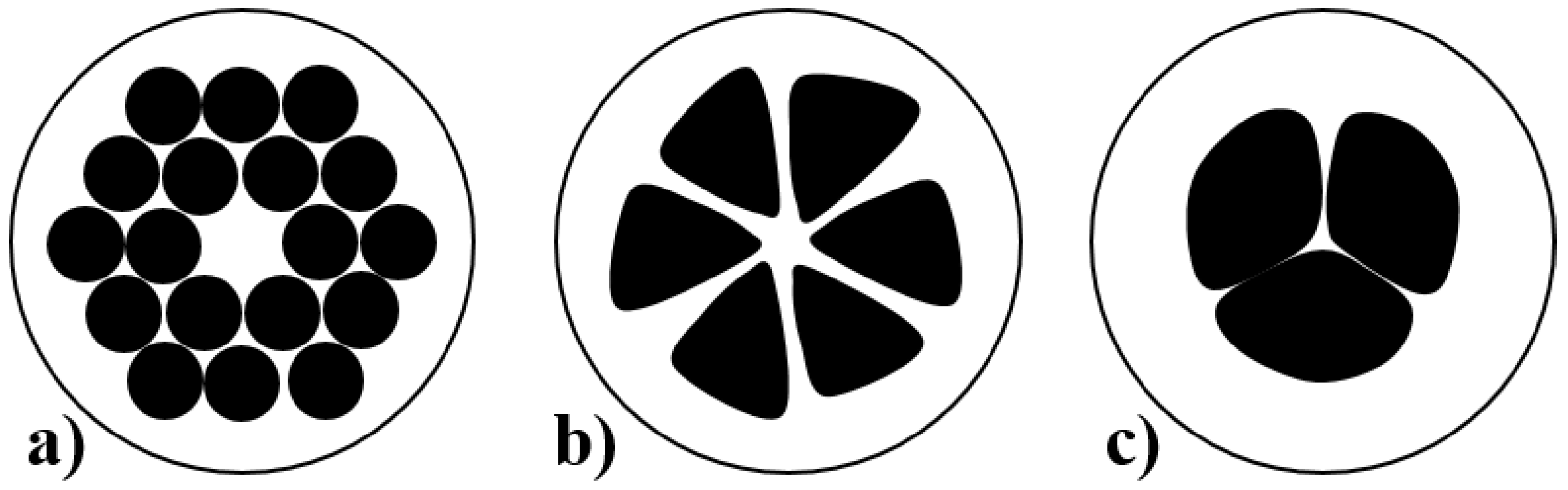
Figure 3.
Global consumption value of fiber optic sensors market forecast. Reproduced with permission from [39], Copyright EletroniCast Consultants, 2017.
Figure 3.
Global consumption value of fiber optic sensors market forecast. Reproduced with permission from [39], Copyright EletroniCast Consultants, 2017.
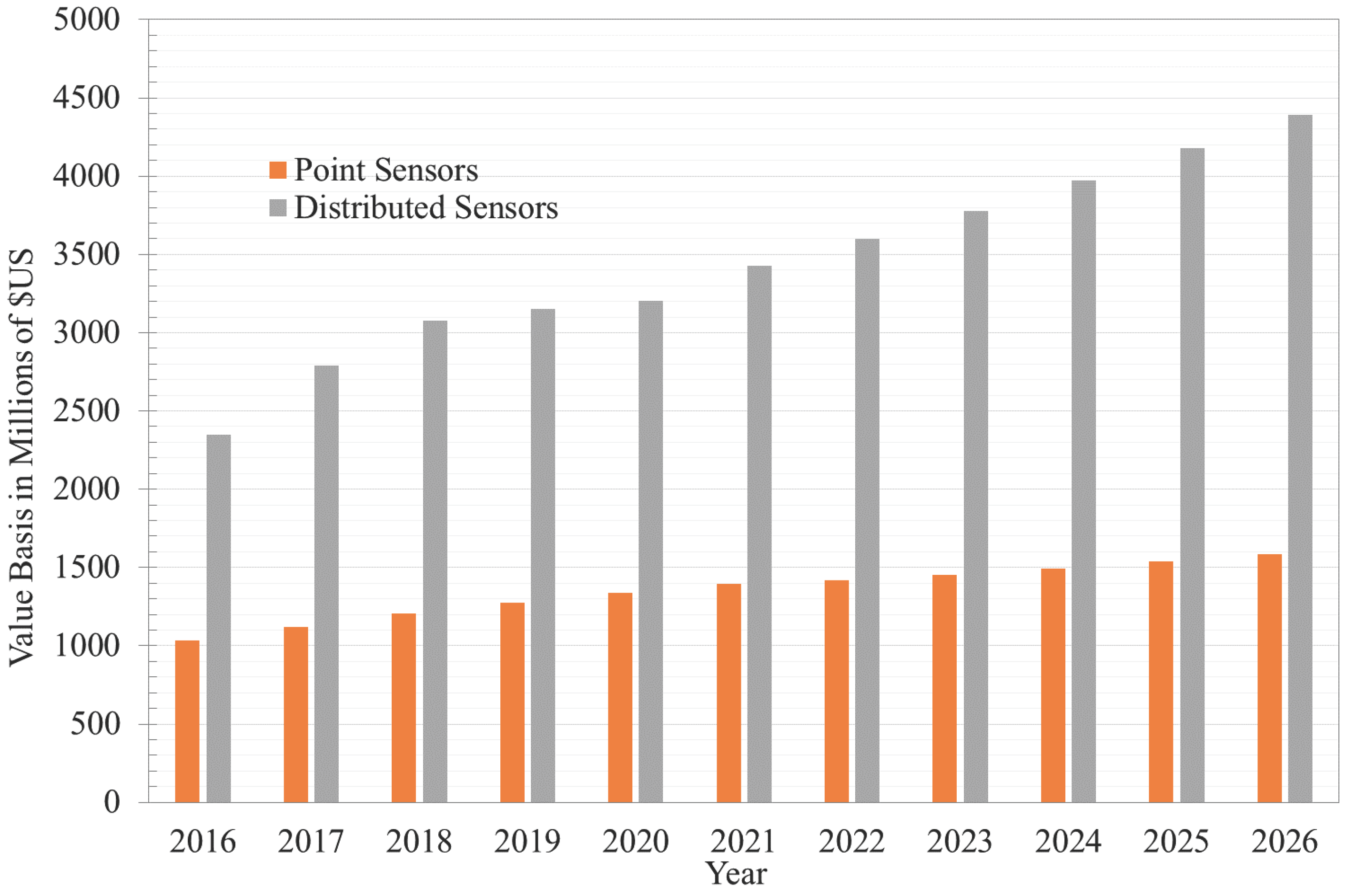
Figure 4.
FBG Network architecture showing prnciple operation of interrogator. Reproduced with permission from [118], Copyright IEEE Photonics Technology Letters, 2008.
Figure 4.
FBG Network architecture showing prnciple operation of interrogator. Reproduced with permission from [118], Copyright IEEE Photonics Technology Letters, 2008.

Figure 5.
Schematic of an All Optical Control System (AOCS). Reproduced with permission from [122], Copyright IEEE, 2003.
Figure 5.
Schematic of an All Optical Control System (AOCS). Reproduced with permission from [122], Copyright IEEE, 2003.


Table 1.
Summary of Fiber Bragg Grating Temperature Sensors.
| Year | Sensitivity | Resolution | Range | Wavelength | Author |
|---|---|---|---|---|---|
| 1990 | 6.8 pm/C | - | - | 850 nm | Morey et. al. |
| 1994 | 10 pm/C | - | - | 1300 nm | Xu et al. |
| 1995 | 13 pm/C | - | - | 1550 nm | Rao et. al. |
| 1997 | - | 0.1/C | 30–60 C | 1550 nm | Rao et. al. |
| - | - | 0.5/C | 20–550 C | - | Mamidi et. al. |
| 2009 | - | up to 1200 C | - | Canning et. al. |
Table 2.
Summary of Fiber Bragg Grating Pressure Sensors in Order of Sensitivity.
| Year | Sensitivity | Range | Wavelength | Author | FBG Type/Novelty |
|---|---|---|---|---|---|
| 1993 | 3 pm/MPa | 70 MPa | - | Xu et. al. | Standard/bare |
| 1996 | 0.3 pm/MPa | 70 MPa | - | Xu et. al. | Standard/bare |
| 2000 | −80 pm/MPa | - | 1540.2 nm | Lui et. al. | Polymer coated/temperature and pressure |
| 2001 | −5.28 nm/MPa | - | 1558 nm | Zhang et. al. | Polymer coated/aluminium cylinder |
| 2007 | −3.77 nm/MPa | - | 1558 nm | Lui et. al. | Polymer coated/copper cylinder |
| 2007 | 7 nm/MPa | - | - | Zhang et. al. | Standard/diaphragm |
| 2009 | 0.244 nm/kPa | - | - | Zhang et. al. | Standard/L-shaped lever |
| 2009 | 48 pm/kPa | - | - | Song et. al. | Standard/metal bellows |
| 2008 | 8.7 nm/MPa | - | - | Ahmad et. al. | Standard/polymer filled casing |
| 2009 | −1.67 nm/MPa | - | - | Ahmad et. al. | Standard/metal diaphragm |
| 2013 | 1.57 pm/kPa | 0–1 MPa | - | Huang et. al. | Standard/diaphragm |
| 2013 | 1.414 pm/kPa | 0–1 MPa | - | Huang et. al. | Standard/Bourdon tube |
| 2012 | 31.67 nm/MPa | - | - | Pachava et. al. | Standard/diaphragm |
| 2012 | 3.55 nm/MPa | - | - | Xiong et. al. | Standard/diaphragm |
| 2007 | 51 pm/MPa | - | - | Bock et. al. | Long period grating |
| 2010 | 9.08 pm/kPa | - | - | Yan et. al. | Photonic crystal fiber |
| 2011 | 265 pm/kPa | - | - | Yan et. al. | Photonic crystal fiber |
| 2006 | 28 pm/MPa | - | - | Hsu et. al. | Standard/temperature insensitive |
| 2011 | 13.4 pm/MPa | - | - | Wu et. al. | Microstructured/temperature and Pressure |
| 2015 | 0.116 nm/kPa | 15 kPa | 1550 nm | Allwood et. al. | Standard/rubber diaphragm |
| 2013 | 1.32 pm/Pa | - | - | Rajan et. al. | Polymer fiber/Vinal diaphragm |
© 2017 by the authors. Licensee MDPI, Basel, Switzerland. This article is an open access article distributed under the terms and conditions of the Creative Commons Attribution (CC BY) license (http://creativecommons.org/licenses/by/4.0/).
Share and Cite
MDPI and ACS Style
Allwood, G.; Wild, G.; Hinckley, S. Fiber Bragg Grating Sensors for Mainstream Industrial Processes. Electronics 2017, 6, 92. https://doi.org/10.3390/electronics6040092
AMA Style
Allwood G, Wild G, Hinckley S. Fiber Bragg Grating Sensors for Mainstream Industrial Processes. Electronics. 2017; 6(4):92. https://doi.org/10.3390/electronics6040092
Chicago/Turabian StyleAllwood, Gary, Graham Wild, and Steven Hinckley. 2017. "Fiber Bragg Grating Sensors for Mainstream Industrial Processes" Electronics 6, no. 4: 92. https://doi.org/10.3390/electronics6040092
Note that from the first issue of 2016, this journal uses article numbers instead of page numbers. See further details here.