Wireless Power Transfer System for Rotary Parts Telemetry of Gas Turbine Engine


Jiangsu Province Key Laboratory of Aerospace Power System, Nanjing University of Aeronautics and Astronautics, Nanjing 210016, China
*
Author to whom correspondence should be addressed.
†
These authors contributed equally to this work.
Electronics 2018, 7(5), 58; https://doi.org/10.3390/electronics7050058
Submission received: 19 March 2018
/
Revised: 17 April 2018
/
Accepted: 17 April 2018
/
Published: 27 April 2018
Abstract
:A novel wireless power transfer approach for the rotary parts telemetry of a gas turbine engine is proposed. The advantages of a wireless power transfer (WPT) system in the power supply for the rotary parts telemetry of a gas turbine engine are introduced. By simplifying the circuit of the inductively-coupled WPT system and developing its equivalent circuit model, the mathematical expressions of transfer efficiency and transfer power of the system are derived. A mutual inductance model between receiving and transmitting coils of the WPT system is presented and studied. According to this model, the mutual inductance between the receiving and the transmitting coils can be calculated at different axial distances. Then, the transfer efficiency and transfer power can be calculated as well. Based on the test data, the relationship of the different distances between the two coils, the transfer efficiency, and transfer power is derived. The proper positions where the receiving and transmitting coils are installed in a gas turbine engine are determined under conditions of satisfying the transfer efficiency and transfer power that the telemetry system required.
1. Introduction
With the ever-increasing demand for power, the work states of aircraft engine components have been pushed to their physical limits. Thus, it is necessary to capture the aircraft engine work states entirely when a new engine is being developed. Because the aircraft engine is a strong nonlinear system with a severe working environment, technologies such as simulation and numerical calculation cannot explain the physical properties of its components completely, even if the basic theories of thermodynamics and kinetics are comparatively mature. Many phenomena and simulations are analyzed through concrete experiments, providing the basis for design and validation. In order to address such problems, the large number of telemetry systems for aircraft engines conducted by general research institutions have become especially important [1,2].
To evaluate the combustion effect of small gas turbine engines, the article by Long et al. [3] developed a telemetry system that can be integrated into an existing engine without affecting its performance. At the same time, in order to prevent the telemetry system from being damaged when the aircraft engine works in high-altitude environments, a cooling system was also designed to ensure the normal operation of the telemetry module. The real-time monitoring of the aircraft engine components is the key to reducing the life cycle cost of a military aircraft. The work of Keyes et al. [4] introduced a high-temperature active wireless telemetry system that could withstand the engine’s poor working environment and provide real-time diagnosis and maintenance. Yang [5] put forward a heat-resistant temperature sensor system based on silicon carbide wireless electronic technology which could be applied to equipment that needs to be monitored and maintained in harsh environments, such as turbines and generators. Extremely poor working environments are the reason why ordinary sensors for monitoring systems cannot work continuously. In order to solve this problem, Mitchell et al. [6] presented an engine component that is integrated with high-temperature sensors and a wireless telemetry system.
In the current scheme, whether it is wireless, laser, or conductive slip ring technology, supply power inevitably needs to be provided to the rotor by battery, conductive slip ring, electromagnetic coupling, etc. With the continuous development of wireless power supply technology, long-distance and high-power radio wireless power supply technology has been greatly improved, and wireless power transfer (WPT) technology is very promising [7,8,9,10,11,12].
In this article, wireless power supply technology was adopted to design a power system for gas turbine engine rotor parameters telemetry. Two key problems has been solved. One is where to install the WPT system on the engine when it is tested on the ground. The other one is that the simulation and test have verified that the WPT system can meet the requirements under the adverse effects of aircraft engine operation, where the axial distance between WPT-TX (Transmitting Unit) and WPT-RX (Receiving Unit) can be changed and the WPT system has coils lateral displacement.
2. Architecture of the WPT System and Analytical Model
2.1. Architecture of the WPT System
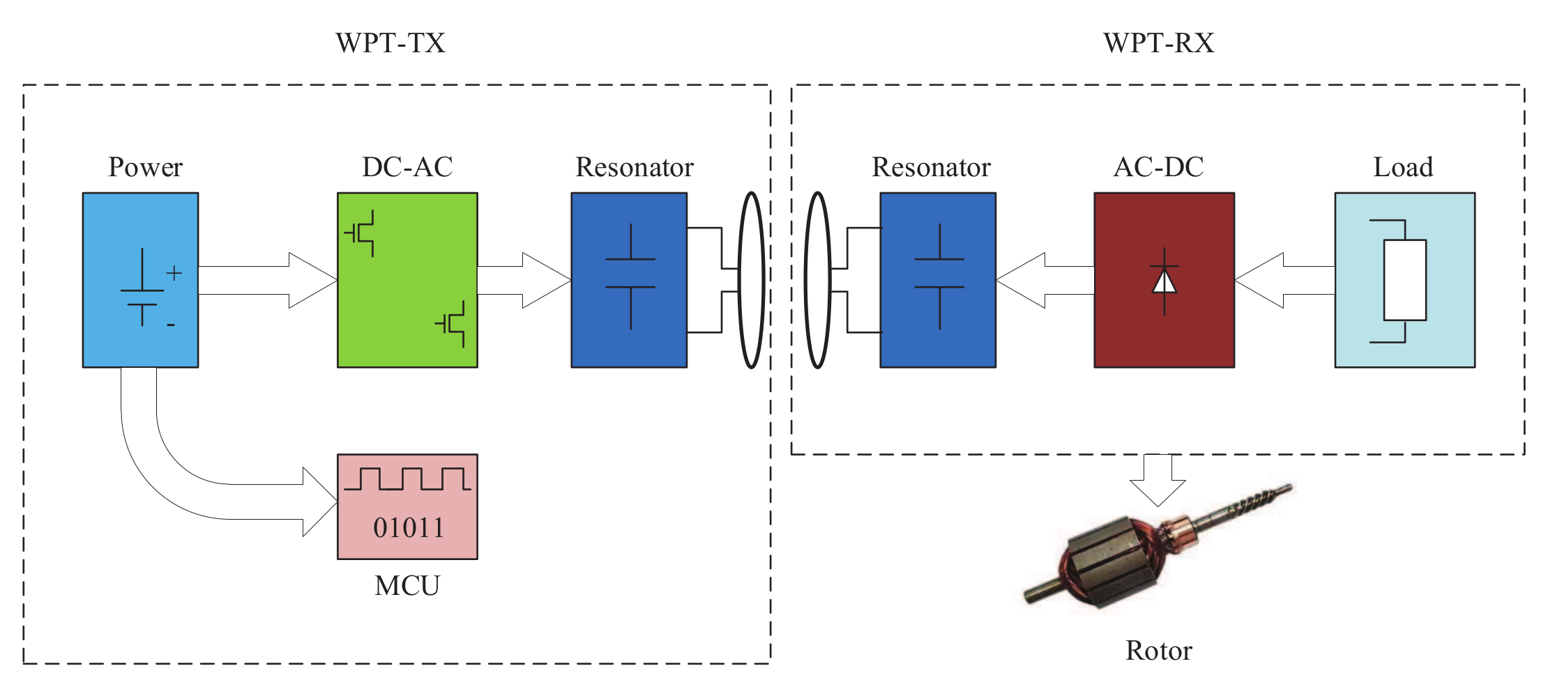
Recently, researches on WPT technology are mostly based on inductively-coupled, magnetically-coupled resonant, microwave radiation, and laser technology [13]. With the exception of immature approaches such as microwave radiation and laser, the others are widely used in many situations. Among these, magnetically-coupled resonant technology is suitable for mid-range WPT situations, and inductively-coupled WPT has the advantage of high efficiency over short distances. Due to the limited space for installing the wireless power transfer system in a gas turbine engine, WPT systems based on inductively-coupled technology are more appropriate. The overall scheme for inductively-coupled WPT systems is presented in Figure 1. The inverter circuit of the transmitting unit converts direct current (DC) to alternating current (AC), and the microprogrammed control unit (MCU) modulates the AC frequency by controlling the switching frequency. Then, the energy goes through the transmitting coil to the receiving unit. Finally, the rectifying circuit of the receiving unit converts AC to DC, which can be applied to the load.
2.2. Analytical Model of the WPT System
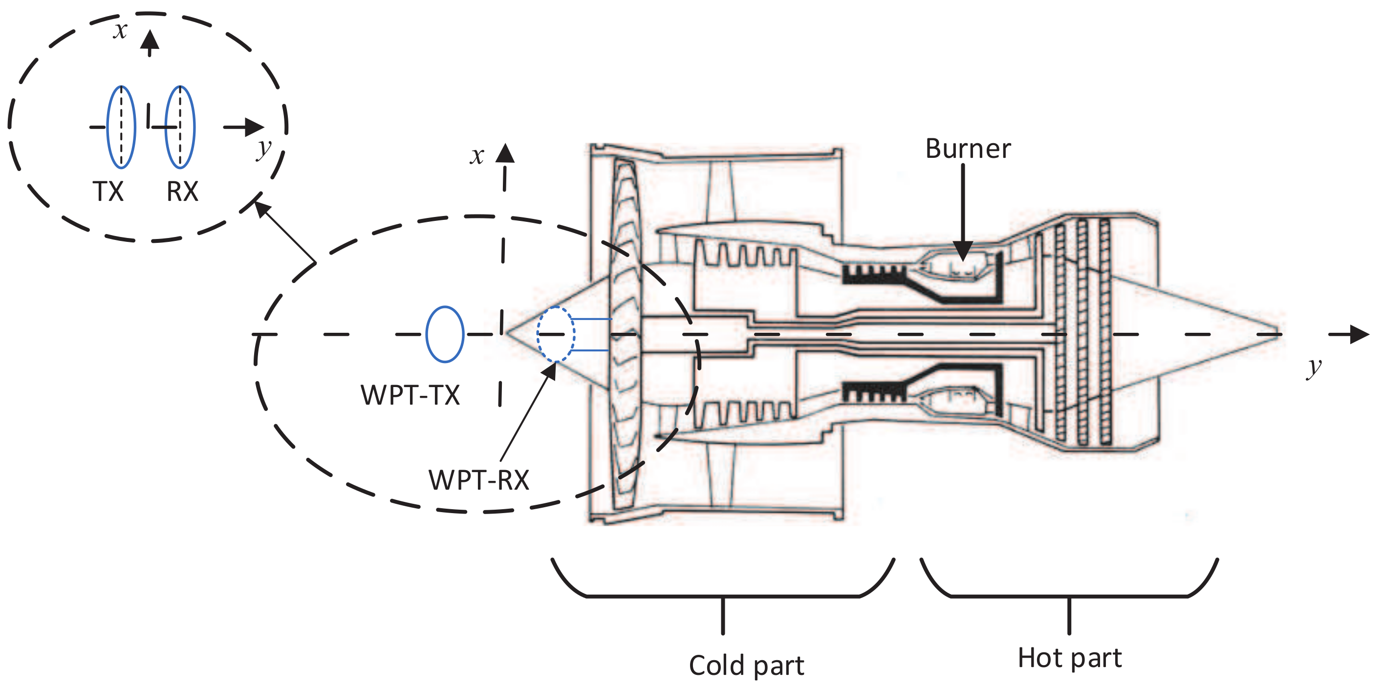
Figure 2 shows a diagram of the WPT system used in the gas turbine engine test, and the WPT system is used in the power supply for the rotary parts telemetry of gas turbine engines. The aircraft engine runs as a heat machine system which is divided into two parts by a burner. The part in front of the burner is called the cold part, and the part after the burner is called the hot part. The WPT-RX is mounted on an axis before the cold part of an aircraft engine and the WPT-TX is located before the engine. The WPT system is designed for ground tests (which means and , where H is altitude and is flight Mach number). In ground tests, the temperature of inlets is near to the environment temperature, so the thermal and mechanical situations of the WPT system are not hard.
The coil planes of WPT-RX and WPT-TX are perpendicular to y-axis, namely the engine shaft. The WPT-RX part provides power supply for sensors in the rotor. There are two important issues that should be considered. One is that primary and secondary coils should be thin and light enough for installation, the other is whether the distance and lateral displacement between the two coils can still meet the requirements of the power transmission. When the engine is running, the rotor shaft will have small deviations, such that the deviations of x-axis and y-axis are typically about 2∼3 mm and 5 mm, respectively. Then, the relative position of TX and RX will be changed, and transmission efficiency and transmission power may also be changed and even could not meet the requirements. In this paper, through theoretical analysis, simulations, and experiments, the appropriate installation position is found to ensure that the WPT system can always meet the requirements, even after axis deviations occur during engine operation.
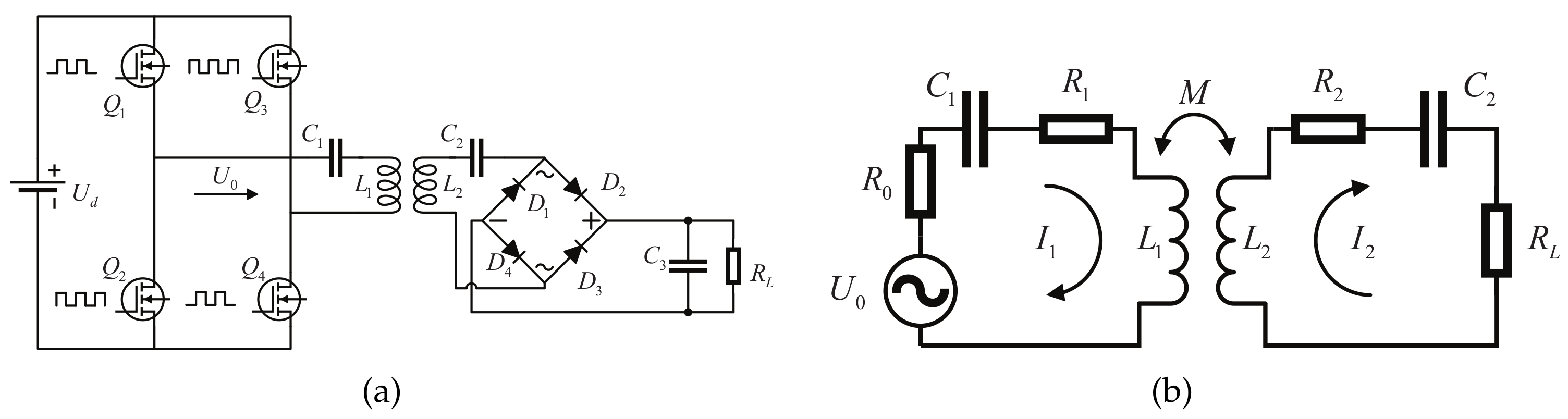
In gas turbine operation, it is necessary to ensure that the WPT system can always meet the requirements, even after axis deviations occur during the engine’s operation. Good performance is demanded with limited weight and size. In order to obtain an optimal design, it is necessary to analyze the overall circuit in detail. Figure 3a shows a circuit model of the WPT system. In order to analyze the transfer efficiency and power further, Figure 3b shows the equivalent circuit model, where , , and respectively are the resonant capacitor, the coil self-inductance, and the coil parasitic resistance at the primary side; is the alternating voltage which is output by a full-bridge inverter circuit; is the sum of the internal resistance of the switch tube and the power source in the full-bridge topology circuit. M is the mutual inductance between two coils; , , and , respectively, are the resonant capacitor, the coil self-inductance, and the coil parasitic resistance at the secondary side; is the load; and are respectively the current of the primary side and secondary side.
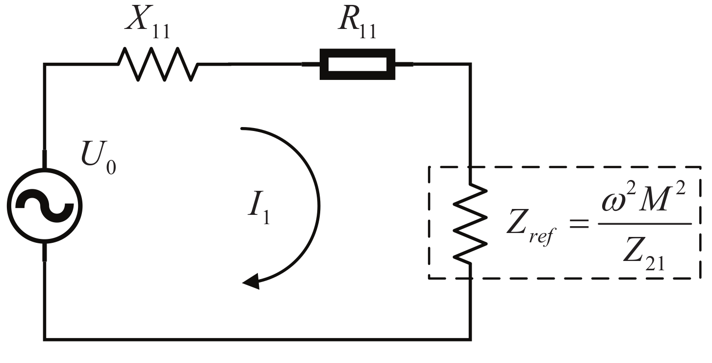
By using the bidirectional reflectance impedance analysis (BRIA) method [14], a simplified circuit model is shown in Figure 4. is the reflected impedance from the secondary coil to the primary coil; is the total impedance of the secondary side; and are, respectively, the reactance and resistance of the primary side. They can be expressed as follows:
where is the resistance of .
where is the reactance of .
Hence, the active power (i.e., output power of this WPT system) consumed by the load of the secondary side and the transfer efficiency can be derived as:
will be increased by reducing the reactive power. When the WPT system is in the resonant state, and are equal to 0. Thus, the reactive power of the system is relatively small. According to Equation (7), the electric current I of this system and reach the maximum in the resonant state (i.e., ), and is also reaching the maximum. Therefore, the operating frequency of this WPT system should be in the vicinity of its resonant frequency. This WPT system must first ensure the power requirement of the telemetry system, and then improve its transfer efficiency gradually. In the resonant state, the expressions of and are as follows:
According to Equations (9) and (10), when the values of , , , , , and the resonant frequency f are fixed, the distance of the two coils affects and by changing the mutual inductance M. So, it is important to study the mutual inductance to properly draw experimental conclusions.
3. Calculation of Mutual Inductance, the Transfer Efficiency, and Transfer Power
3.1. Calculation of Mutual Inductance
Figure 5 shows the energy transmission process of this WPT system. The mutual inductance value depends on the shape, size, number of turns, relative position of the two coils, and the permeability of surrounding media. It often has coils lateral displacement when using the WPT system for supplying the power for the rotary parts telemetry of gas turbine engines, as shown in Figure 6a. In order to derive the expression of mutual inductance easily, we focus on the shape of a single turn coil, where and are the radius of transmitting and receiving coils (i.e., the primary and secondary coils), respectively; h is the axial distance; x represents the lateral displacement.
Neumann’s equation is employed to calculate M between two coils [15]. Thus, M can be computed by the following equation [16]:
The distance between two arbitrary points respectively on the two coils is presented as:
To calculated M easily, let us introduce parameters , , and . M can be expressed as:
Figure 6b shows the configuration of two coils with non-lateral displacement. It could be a special case of the two coils with lateral displacement (i.e., ). Thus, M can be expressed as follows:
The electromagnetic field generated by a current system of any complexity and shape can be evaluated by superposing the field contributions generated by elementary structures. Mutual inductance is generated by two interacting coils, thus it can be calculated by the superposition principle. and are respectively the inner diameters of the primary and secondary coil; and are primary and secondary copper track widths, respectively; and are primary and secondary track separations, respectively; and and are respectively the number of turns in the primary and secondary sides. Therefore, M can be expressed as follows:
where , . The parameters of the two coils are shown in Table 1.
3.2. The Computational Analysis of the Transfer Efficiency and Transfer Power
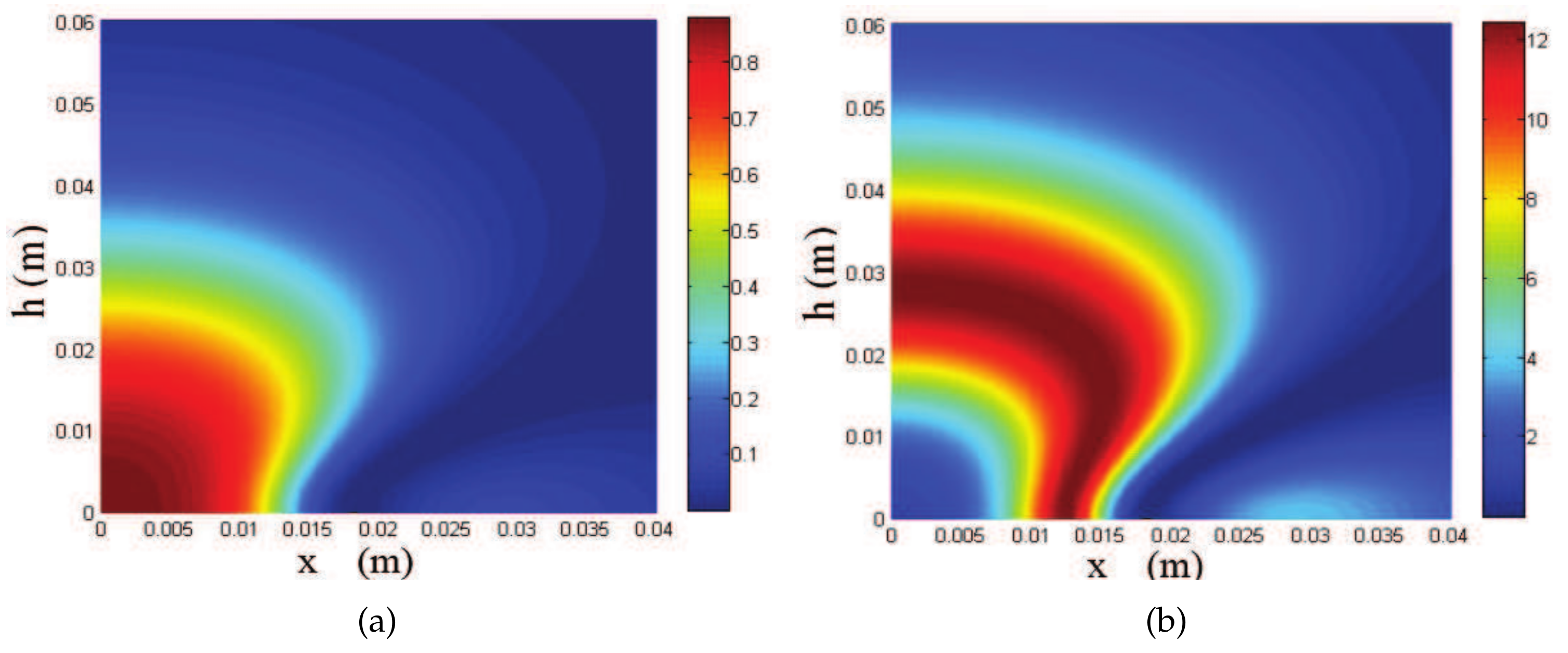
Table 2 shows the parameters of the WPT system components in the test. In the simulation, the switching frequency was equal to the resonant frequency, and the WPT system supply voltage was 10 V. The effective value of AC voltage that the full-bridge inverter circuit outputs was 9 V, and the reason will be explained in the next section. According to Equations (5)–(7), it will draw two pictures. One represents the relationship of the distance between the two coils and transfer efficiency, the other represents the relationship of the distance between the two coils and the load power in the resonant state, as shown in Figure 7a,b, respectively.
As shown in Figure 7a, transfer efficiency of the WPT system decreases as the axial distance or lateral displacement between two coils increases. The simulation results show that the lateral displacement has a greater influence on transfer efficiency than the axial distance. There are some points where both of their axial distances and lateral displacement are different, but their mutual inductances and transfer efficiencies are the same. Figure 7b shows that the load power of this system increases at first and decreases subsequently as the axial distance or lateral displacement between two coils increases. In Equations (9) and (10), there is only one variable M. As the axial distance or lateral displacement increase, M decreases and the value of increases, and then transfer efficiency decreases. In the expression of , is a hook function. As M decreases, may decrease, increase, or first increase and then decrease. Therefore, as shown in Figure 7b, the variation is normal. Under the condition that it meets the power requirement of the telemetry system, the highest-efficiency points could save energy. Combined with the two pictures, it is better to maintain the vertical distance between RX and TX in 20∼30 mm when the WPT system is applied to a gas turbine engine. Although efficiency is not the highest, when the deviations of two axes are less than 10 mm, the WPT system can still provide enough power, in excess of 9 W.
4. Design Objective of the WPT System and Analysis of Experimental Data
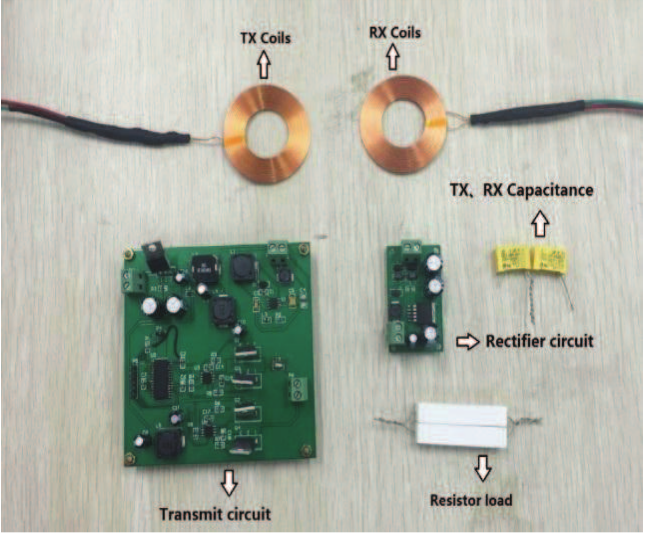
The test device of the WPT system is shown in Figure 8. Because equivalent resistance of the rectifying circuit of the receiving unit could not be calculated, it will be removed in the test to ensure the veracity of the model. The load resistance 2.55 W, was used to test the capacity of this WPT system. The supply voltage of the WPT system was , and the magnitude of voltage of capacitor and transmitting coils in the primary side was equal to . By Fourier series expansion of , the expression can be derived as follows:
According to Equation (17), the fundamental wave effective value is expressed as:
Thus, the effective value of AC voltage was 9 V. The total power of the WPT system can be calculated by the voltage and current of the stabilized voltage supply. At the same time, the power expended in the load can be calculated by the effective value of sinusoidal voltage on the load resistance. The transfer efficiency of this system is defined as the ratio of the power expended in the load and total power of the WPT system. In the test, parameters including simulation frequency f, axial distance h, and lateral displacement x were changed.
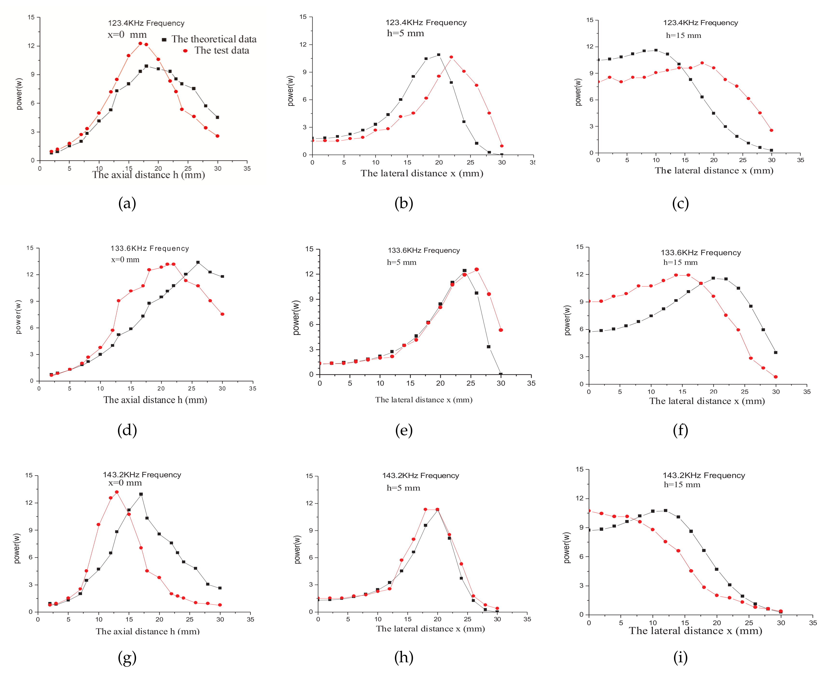
Figure 9 shows the changing curve of the load power with the simulation frequency and the distance of two coils. The pictures ((a), (d), and (g)) show two changing curves of the load power by changing axial distance when x equals 0, which respectively represent the test and theoretical data. It is obvious that their variation trends are compatible, and it proves that the models of mutual inductance and the circuit were effective. Pictures (b), (e), and (h) and the other pictures (c), (f), and (i) respectively show the changing curve of the load power by changing lateral distance when h was about 5∼10 mm. Overall, all nine pictures show that the variation trend of the load power first increased and then decreased as the distance between the coils increased. However, there were some test data points which were quite different from theoretical values. There are two reasons for this, one is the limit of measuring tools such as the digital oscilloscope (DS1102E), and the other may be ignoring the skin effect.
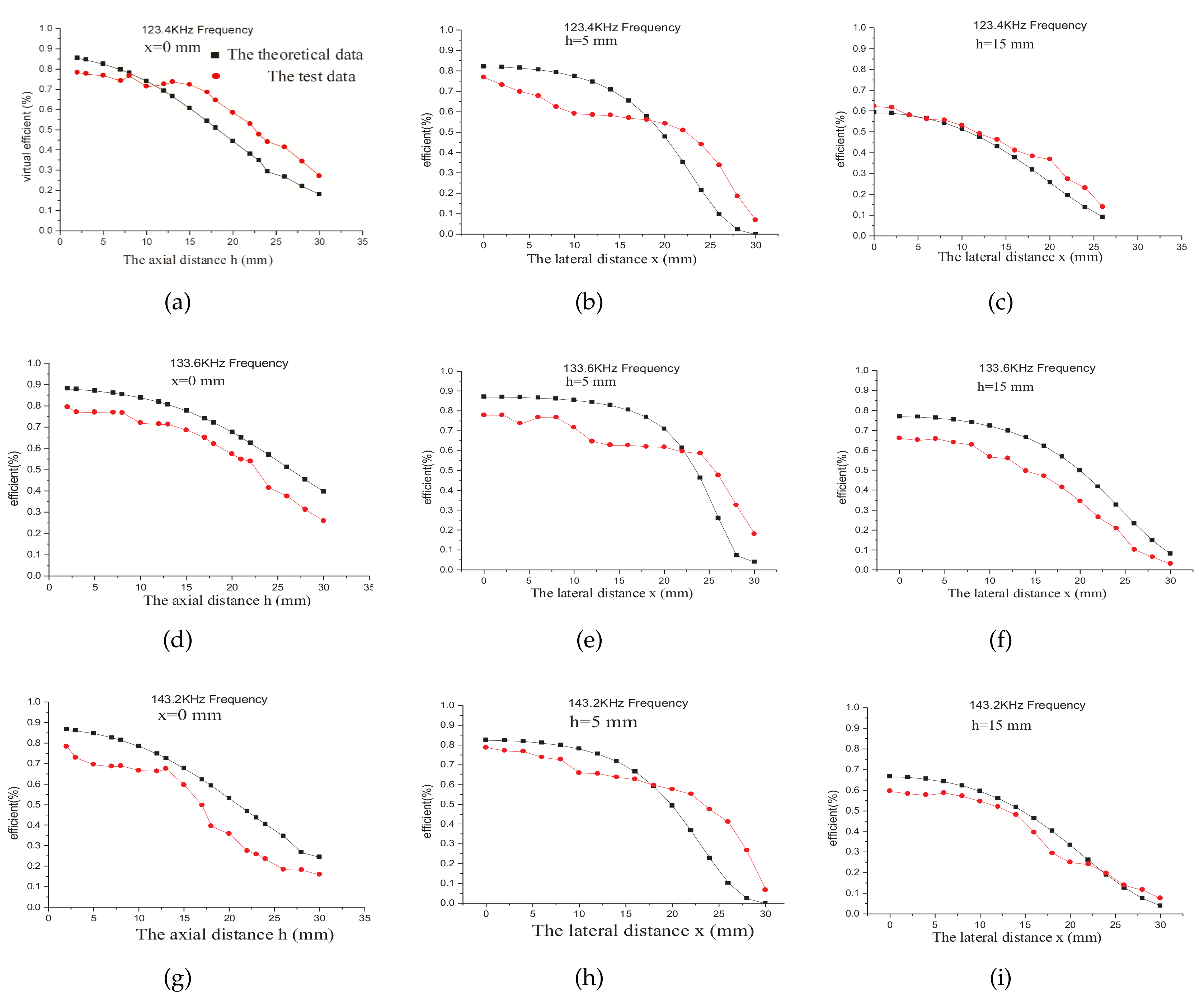
Figure 10 is similar to Figure 9, but Figure 10 shows the variation of the transfer efficiency. It also shows that transfer efficiency decreases as axial distance h or lateral displacement x increases. Its variation tendency agrees well with the theoretical analysis, once again proving that the models of mutual inductance and the circuit are effective. Comparing the transfer efficiencies in different frequencies, it can be concluded that the maximum transfer efficiency can be achieved only in the resonant state. Thus, the resonant frequency was made for the WPT system in practice.
In summary, combined with Figure 9 and Figure 10, the changing trends of load power and transfer efficiency in the test were consistent with the theoretical trends that are shown in Figure 7a,b. Compared to the transmission efficiency, the power needs to be satisfied first. The appropriate range of vertical distance is 14∼28 mm, because load power is higher than 9 W in this scope, and when the lateral distance is from 0 to 20 mm, load power is still higher than 9 W. Meanwhile, considering that transfer efficiency and load power decrease with the increase of distance, smaller vertical distance is better.
To meet the operating conditions of the electronic device of the rotary parts, the use of DC voltage is required. Though the use of synchronous rectification makes rectifier efficiency high, a suitable electric power supply must be provided for the metal–oxide–semiconductor field-effect transistor (MOSFET) or insulated gate bipolar transistor (IGBT) driver chip, and then the additional power will be increased. Although using a rectifier chip such as KBU1000 could switch AC to DC directly, its efficiency is low. However, using a bridge rectifier circuit composed of Schottky diodes has not only high efficiency but also a simple circuit. Table 3 shows the load power when the bridge rectifier circuit was used or not. When the frequency was 133.6 KHz (i.e., a resonant frequency), x equaled 5 mm and h equaled about 20∼25 mm. If there was no capacitor-filter and inductance filter in the rectifier circuit, the reactivity of the system was not increased. Thus, the power load can also be calculated by the magnitude of sinusoidal voltage on the load.
As shown in Table 3, the rectifier efficiency values of bridge rectifier circuit were over 85%, and when the voltage drop of the bridge of diodes rectifier circuit reduced and the resistance value increased, the rectifier efficiency of the bridge rectifier circuit increased. With the advent of an ideal diode such as LTC4415, the rectifier efficiency necessarily increases. Because of the high rectifier efficiency, the calculation that ignores the rectifier has practical application in the receiving unit of the WPT system. The working requirement of the electronic device of the rotary parts is low. Therefore, when it has coils lateral displacement, the WPT system could also be suitable.
5. Conclusions
By taking the inductively coupled WPT system as a model and the distance between receiving and transmitting coils as a variable, this paper studies the relation between the coil distance, transfer efficiency, and transfer power of the WPT system, and the mutual inductance model and the system circuit model are validated. The test data and the theoretical analysis prove that the WPT system could ensure the working requirements of the rotary parts telemetry of gas turbine engines, and also provide a reference to find a suitable position to install the primary and secondary coils on the gas turbine engine. Although there was a gap (less than 10 mm) between the vertical distances that correspond to theoretical and test peak of load power, the changing trends of load power and transfer efficiency in the test were consistent with theoretical trends, and the values of theoretical and test peaks were almost the same. The results of test show that the appropriate range of vertical distance of two coils is from 14 mm to 28 mm. In this scope, the load power was higher than 9 W, and when the lateral distance was in 0∼20 mm, the load power was still higher than 9 W.
This paper provides a practicable scheme for a WPT system for the rotary parts telemetry of gas turbine engines. Even though the load circuit is more complex and the load resistance value is more than 2.5 , it can calculate the changing curves of transfer efficiency and transfer power at some distance between two coils through building a mutual inductance model and a system circuit model, and then the proper installation locations of the receiving and transmitting coils can be determined.
Author Contributions
X.H., W.S. and B.Y. conceived and designed the system and experiments; W.S. and X.M. performed the experiments; X.H. and W.S. analyzed the data; W.S. wrote the paper.
Acknowledgments
This work is supported by the Fundamental Research Funds for the Central Universities (no. NJ20160037).
Conflicts of Interest
The authors declare no potential conflict of interest.
References
- Simon, D.L.; Garg, S.; Hunter, G.W.; Guo, T.H.; Semega, K.J. Sensor Needs for Control and Health Management of Intelligent Aircraft Engines. NTRS 2004, 873–882. [Google Scholar] [CrossRef]
- Yan, H.X.; Zhang, T.H.; Sun, J.G. Design of codec for FIR used in the telemetry of aeroengine rotor. J. Aerosp. Power 2007, 22, 495–499. [Google Scholar]
- Long, S.A.; Reiger, P.; Elliott, M.W.; Edney, S.L.; Knabe, F.; Bernhard, D. Application of a Miniature Telemetry System in a Small Gas Turbine Engine. In Proceedings of the ASME 2011 Turbo Expo: Turbine Technical Conference and Exposition, Vancouver, BC, Canada, 6–11 June 2011. [Google Scholar]
- Keyes, B.; Brogan, J.A.; Gouldstone, C.; Greenlaw, R.; Yang, J.; Fraley, J.; Western, B.; Schupbach, M. High temperature telemetry systems for in situ monitoring of gas turbine engine components. In Proceedings of the 2009 IEEE Aerospace Conference, Big Sky, MT, USA, 7–14 March 2009; pp. 1–15. [Google Scholar]
- Yang, J. A Silicon Carbide Wireless Temperature Sensing System for High Temperature Applications. Sensors 2013, 13, 1884–1901. [Google Scholar] [CrossRef] [PubMed]
- Mitchell, D.J.; Kulkarni, A.; Lostetter, A.; Schupbach, M.; Fraley, J.; Waits, R. Development and Testing of Harsh Environment, Wireless Sensor Systems for Industrial Gas Turbines. In Proceedings of the ASME Turbo Expo 2009: Power for Land, Sea, and Air, Orlando, FL, USA, 8–12 June 2009; pp. 777–784. [Google Scholar]
- Wang, C.; Stielau, O.H.; Covic, G.A. Design considerations for a contactless electric vehicle battery charger. IEEE Trans. Ind. Electron. 2005, 52, 1308–1314. [Google Scholar] [CrossRef]
- Kurs, A.B.; Karalis, A.; Moffatt, R.; Joannopoulos, J.D.; Fisher, P.H.; Soljacic, M. Wireless Power Transfer via Strongly Coupled Magnetic Resonances. Science 2007, 317, 83–86. [Google Scholar] [CrossRef] [PubMed]
- Lee, S.H.; Lorenz, R.D. Development and Validation of Model for 95%-Efficiency 220-W Wireless Power Transfer Over a 30-cm Air Gap. IEEE Trans. Ind. Appl. 2011, 47, 2495–2504. [Google Scholar] [CrossRef]
- Serrano, J.; Acero, J.; Alonso, R.; Carretero, C.; Lope, I.; Burdío, J. Design and Implementation of a Test-Bench for Efficiency Measurement of Domestic Induction Heating Appliances. Energies 2016, 9, 636. [Google Scholar] [CrossRef]
- Wang, Z.; Wei, X.; Dai, H. Design and Control of a 3 kW Wireless Power Transfer System for Electric Vehicles. Energies 2016, 9, 10. [Google Scholar] [CrossRef]
- Lope, I.; Acero, J.; Carretero, C. Analysis and Optimization of the Efficiency of Induction Heating Applications With Litz-Wire Planar and Solenoidal Coils. IEEE Trans. Power Electron. 2016, 31, 5089–5101. [Google Scholar] [CrossRef]
- Xingmin, F. Research status and application of wireless power transmission technology. Zhongguo Dianji Gongcheng Xuebao 2015, 35, 2584–2600. [Google Scholar]
- Wei, X.; Wang, Z.; Dai, H. A Critical Review of Wireless Power Transfer via Strongly Coupled Magnetic Resonances. Energies 2014, 7, 4316–4341. [Google Scholar] [CrossRef]
- Zhaoan, W.; Jinjun, L. Electronic Power Technology; China Machine Press: Beijing, China, 2009. [Google Scholar]
- Grover, W.F. Inductance Calculations Working Formulas and Tables; Courier Corporation: Mineola, NY, USA, 2004. [Google Scholar]
Figure 1.
Wireless power transfer (WPT) system composition. AC: alternating current; DC: direct current; MCU: microprogrammed control unit; WPT-TX: transmitting unit of WPT; WPT-RX: receiving unit of WPT.
Figure 1.
Wireless power transfer (WPT) system composition. AC: alternating current; DC: direct current; MCU: microprogrammed control unit; WPT-TX: transmitting unit of WPT; WPT-RX: receiving unit of WPT.

Figure 2.
Diagram of the WPT system used in the gas turbine engine test.

Figure 3.
(a) Circuit model of the WPT system; (b) Equivalent circuit model of the WPT system.

Figure 4.
Simplified circuit model of the WPT system.

Figure 5.
Energy transmission process of the WPT system.

Figure 6.
(a) Configuration of the filamentary coils with lateral displacement; (b) Configuration of filamentary coils with non-lateral displacement.
Figure 6.
(a) Configuration of the filamentary coils with lateral displacement; (b) Configuration of filamentary coils with non-lateral displacement.

Figure 7.
(a) Relationship of the distance between the two coils and transfer efficiency in the resonant state; (b) Relationship between the two coils and the load power in the resonant state.
Figure 7.
(a) Relationship of the distance between the two coils and transfer efficiency in the resonant state; (b) Relationship between the two coils and the load power in the resonant state.

Figure 8.
The test device of the WPT system.

Figure 9.
Changing curve of the load power with the simulation frequency and the distance of two coils. (a) ; (b) ; (c) ; (d) ; (e) ; (f) ; (g) ; (h) ; (i) .
Figure 9.
Changing curve of the load power with the simulation frequency and the distance of two coils. (a) ; (b) ; (c) ; (d) ; (e) ; (f) ; (g) ; (h) ; (i) .

Figure 10.
Changing curve of the transfer efficiency with the simulation frequency and the distance of two coils. (a) ; (b) ; (c) ; (d) ; (e) ; (f) ; (g) ; (h) ; (i) .
Figure 10.
Changing curve of the transfer efficiency with the simulation frequency and the distance of two coils. (a) ; (b) ; (c) ; (d) ; (e) ; (f) ; (g) ; (h) ; (i) .


Table 1.
Parameters of TX and RX.
| Coil | Radius | Track Separation Width | Copper Track | Number of Turns | Self-Inductance | Internal Resistance |
|---|---|---|---|---|---|---|
| (mm) | (mm) | (mm) | (n) | (H) | () | |
| 12.5 | 0 | 0.6 | 25 | 29.26 | 0.30 | |
| 12.5 | 0 | 0.6 | 25 | 29.22 | 0.31 |
Table 2.
Parameters of the components of this WPT system.
| Parameters | Value |
|---|---|
| / | 2.55 |
| / | 0.9 |
| /nF | 50.93 |
| /nF | 52.51 |
| The effective value of /V | 9 |
| The resonant frequency f/KHz | 133.6 |
Table 3.
Load power of the system when using bridge rectifier circuit or not using it.
| h | Rectifier Load Power | Non-Rectifier Load Power | The Ratio between and |
|---|---|---|---|
| (mm) | (W) | (W) | (%) |
| 20 | 7.052 | 8.085 | 87.2 |
| 21 | 8.590 | 9.718 | 88.3 |
| 22 | 9.386 | 10.522 | 89.2 |
| 23 | 9.366 | 10.524 | 88.9 |
| 24 | 9.324 | 10.520 | 88.6 |
| 25 | 8.664 | 9.982 | 86.7 |
© 2018 by the authors. Licensee MDPI, Basel, Switzerland. This article is an open access article distributed under the terms and conditions of the Creative Commons Attribution (CC BY) license (http://creativecommons.org/licenses/by/4.0/).
Share and Cite
MDPI and ACS Style
He, X.; Shu, W.; Yu, B.; Ma, X. Wireless Power Transfer System for Rotary Parts Telemetry of Gas Turbine Engine. Electronics 2018, 7, 58. https://doi.org/10.3390/electronics7050058
AMA Style
He X, Shu W, Yu B, Ma X. Wireless Power Transfer System for Rotary Parts Telemetry of Gas Turbine Engine. Electronics. 2018; 7(5):58. https://doi.org/10.3390/electronics7050058
Chicago/Turabian StyleHe, Xiaoming, Wenjun Shu, Bing Yu, and Xiaodong Ma. 2018. "Wireless Power Transfer System for Rotary Parts Telemetry of Gas Turbine Engine" Electronics 7, no. 5: 58. https://doi.org/10.3390/electronics7050058
Note that from the first issue of 2016, this journal uses article numbers instead of page numbers. See further details here.