

Continuous Acceleration Sensing Using Optomechanical Droplets

Department of Physics and Scottish Universities Physics Alliance (SUPA), University of Strathclyde, Glasgow G4 0NG, UK
*
Author to whom correspondence should be addressed.
Atoms 2024, 12(3), 15; https://doi.org/10.3390/atoms12030015
Submission received: 16 December 2023
/
Revised: 21 February 2024
/
Accepted: 28 February 2024
/
Published: 6 March 2024
(This article belongs to the Special Issue Cold and Rydberg Atoms for Quantum Technologies)
Abstract
:We show that a Bose–Einstein Condensate illuminated by a far off-resonant optical pump field and its retroreflection from a feedback mirror can produce stable, localised structures known as optomechanical droplets. We show that these droplets could be used to measure the acceleration of a BEC via continuous monitoring of the position of the droplet via the optical intensity distribution.
1. Introduction
The utility of cold atomic gases and Bose–Einstein Condensates (BECs) for applications involving sensing of various quantities (from acceleration to electromagnetic fields) has been recognised for many years now [1,2,3,4,5,6,7]. In acceleration sensing involving ultracold atoms or BECs, many traditional measurement techniques such as time-of-flight measurements are destructive, with each measurement requiring a new sample of atoms [4]. Dispersive imaging techniques which utilise the refractive properties of the atoms have been used [8,9,10,11,12] to realise non-destructive imaging of BECs.
Recently, there has been interest in continuous, minimally destructive sensing of acceleration via interaction of a BEC with light contained within an optical cavity [13,14,15,16,17,18]. The dynamical behaviour of the BEC under the action of an external force, e.g., gravity, influences the dynamical behaviour of the optical field in the cavity; the BEC dynamics can be inferred from measurement of the optical field escaping from the cavity and the acceleration of the BEC can be calculated. This concept has been considered in several different configurations involving both Fabry–Perot and ring cavities where the BEC exhibits Bloch oscillations due to its acceleration through a spatially periodic optical lattice [19] consisting of counterpropagating cavity modes alone [13,14,15,16] or by adding an externally applied optical lattice [17,18].
The interaction between cold atoms/BECs and light in an optical cavity has also attracted significant interest due to the existence of self-organisation phenomena, e.g., self-organised optical/atomic patterns [20,21,22,23,24,25]. Self-organized structures and patterns can also be produced by the simultaneous presence of optical nonlinearity and diffraction. These patterns have been predicted and observed in a variety of nonlinear media [26,27,28,29,30,31,32,33,34,35] specifically including atomic vapours [26,27,28,29,30,31,36,37,38]. In the case of cold atoms/BECs, the origin of optical nonlinearity is the spatial modulation of atomic density which arises due to the mechanical effect of light, specifically optical dipole forces. Formation of a spatially modulated atomic density and its subsequent backaction on light give rise to an optomechanical self-structuring instability, resulting in the simultaneous, spontaneous formation of atomic density structures and optical intensity structures. Optomechanical self-structuring of a cold thermal gas has been studied experimentally and theoretically in systems of counterpropagating beams [39,40] and in a single mirror feedback (SMF) configuration [41,42,43]. Theoretical predictions of optomechanical self-structuring in a BEC [44] highlighted that a significant difference with the classical, thermal gas is the the dispersive nature of the BEC wavefunction, i.e., “quantum pressure”, which acts to suppress density modulations or spatial structures in the BEC. Recent work has shown that optomechanical self-structuring in a BEC can produce spatially localised structures termed “droplets” or “quantum droplets” [45,46,47] in addition to global patterns. These droplets are self-bound structures consisting of interacting light and matter whose stability is reliant upon the BEC quantum pressure. They display some similar characteristics to quantum droplets in other systems such as dipolar BECs [48] and quantum liquids [49] but also have some properties similar to those of other varieties of spatially localised structures, e.g., spatial solitons [50]. In this paper, we study the dynamical behaviour of these optomechanical droplets in a 1D configuration involving a single feedback mirror, as in [45,46], and consider the effect of a uniform BEC acceleration, shown schematically in Figure 1.
2. Model
We investigate the system shown schematically in Figure 1 consisting of a BEC with single mirror feedback (SMF). In this BEC–SMF system, coupling between atoms arises due to their interaction with a pump optical field and its reflection from the feedback mirror. Diffraction of the optical field as it propagates from the BEC to the mirror and back again plays a critical role in this coupling. The interaction involves many transverse modes and optical forces directed perpendicular to the propagation direction of the optical fields. A significant difference between this system and other cavity systems displaying self-organization (such as e.g., [51,52]) is that interference between the optical fields does not play a significant role in this system, whereas in. [51,52] the dominant coupling between atoms arises from interference between a pump field and cavity modes. We demonstrate the existence of spatially localised states with characteristics similar to those of quantum droplets observed in dipolar BECs [53,54] and the effect of uniform acceleration on these droplets.
The model we use to describe the BEC–SMF system was originally studied in [44]. We consider a BEC with a negligible scattering length and describe the evolution of the BEC wavefunction, , with the Schrödinger equation:
where and are dimensionless time and space variables, is a critical wavenumber to be defined shortly, is the decay rate of the atomic transition and is a dimensionless recoil frequency, where m is the atomic mass. The quantities and are the atomic saturation parameters due to the forward and backward optical fields defined as and , respectively. is a dimensionless detuning parameter where is the detuning between the optical field frequency, , and the atomic transition frequency, , and and are the intensities of the forward (F) and backward (B) fields, respectively. is the saturation intensity on resonance. It has been assumed that the optical fields are far-detuned from atomic resonance () and that consequently so that the atoms remain in their ground state. In addition, any effects of gratings formed along the propagation (z) axis due to interference between the counterpropagating optical fields are neglected.
In order to describe the evolution of the optical field in the BEC, we assume that the gas is diffractively thin; i.e., it is sufficiently thin that diffraction can be neglected. Consequently, the forward field transmitted through the cloud is
where is the scaled pump intensity, is the susceptibility of the BEC, is the optical thickness of the BEC at resonance and is the local BEC density, which for a BEC of uniform density is .
After propagation of this transmitted forward field from the BEC to the feedback mirror in free space, the reflected backward field, B, at the BEC completes the feedback loop. As the field propagates a distance from the BEC to the mirror and back, optical phase modulations induced by transmission through density modulations in the BEC are converted to optical amplitude modulations and consequently optical dipole forces. The Fourier components of the forward and backward fields at the BEC are related by
where R is the mirror reflectivity, q is the transverse wavenumber and . It was shown in [44] that this system exhibits a self-structuring instability, where the optical fields and BEC density develop modulations with a spatial period of , where the critical wavenumber, , is
It can be seen from Equation (4) that can be varied by changing d, the mirror distance from the atomic cloud. Typical values of used for thermal gases are 50–150 m and we anticipate 5–20 m to be suitable for a BEC experiment, corresponding to mirror distances in the range of 8–150 m. As typical BEC thicknesses are in the range of 1–10 m, we expect from previous investigations that the “thin diffractive medium” approximation still holds qualitatively and certainly gives a good initial indication useful for first demonstration of the principle discussed here. Ref. [43] describes a more rigorous theoretical model for thermal atoms, taking diffraction within the medium into account.
The origin of the instability is BEC density modulations (which create refractive index modulations) with spatial frequency . These density modulations in turn produce optical phase modulations in , which then are converted into optical intensity modulations of the reflected field B at the BEC (see Equation (3)). These optical intensity modulations result in dipole forces which act to reinforce the BEC density modulations, providing positive feedback and consequently instability of the initial, homogeneous state. In order to realise this instability, the pump intensity must exceed a threshold value, [44], which for can be written as
where .
3. Existence of Optomechanical Droplets
Numerical simulations of the BEC–SMF model, Equations (1)–(3), using an initial condition where the BEC density is initially a Gaussian function of position, i.e.,
show that for certain BEC widths, , the BEC profile remains constant as time evolves, as shown in Figure 2.
This behaviour is consistent with simulations involving integration of the BEC–SMF model, Equations (1)–(3), in imaginary time [55], which show that the ground state of the BEC + optical field system is a localised droplet state.
It was shown in [56] that it is possible to map the BEC–SMF model, Equations (1)–(3), onto the quantum Hamiltonian Mean Field (quantum HMF) model, a Gross–Pitaevskii-like equation for the BEC wavefunction, , involving a non-local potential. The quantum HMF model is known to possess soliton solutions [57] which correspond to the localised optomechanical droplets which occur in the BEC–SMF simulations (Figure 2). They can be understood as BEC gap solitons in an optical lattice which is self-generated by the BEC [57].
The width of a stable droplet can be calculated by assuming a Gaussian BEC density profile as in Equation (6) and minimising the energy, , of the system, resulting in [56]
where has been assumed. From the parameters used for Figure 2, the predicted stable droplet width from Equation (7) is , which agrees well with the value calculated from simulations shown in Figure 2, which shows that a droplet of this width (which in the figure corresponds to a width ) is a stable, stationary solution.
4. Continuous Acceleration Sensing Using Optomechanical Droplets
We now investigate the behaviour of these droplets under uniform acceleration. Modifying the Schrödinger equation, Equation (1), to include uniform acceleration results in
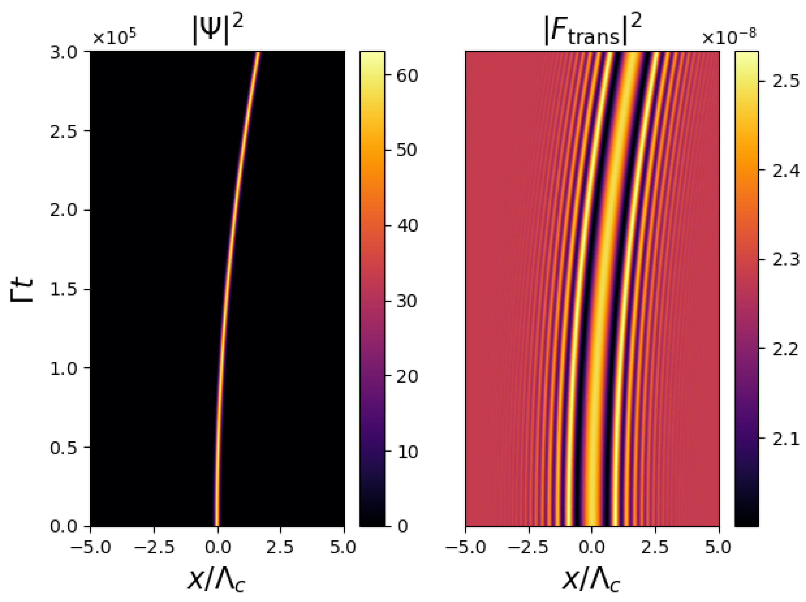
where is a dimensionless acceleration parameter [13,14,15,16,17,18,47]. Figure 3 shows the evolution of the BEC density and the optical fields. Uniform acceleration of BEC can be observed, and the optical field follows this motion, with the BEC density coinciding with an optical intensity maximum.
Figure 3 shows that via continuous observations of the optical intensity distribution, it is possible to infer the dynamical evolution of the BEC density.
In order to perform a quantitative calculation of the uniform acceleration experienced by the BEC, we can use the fact that the position of an object undergoing uniform acceleration is described by
so consequently
Figure 4 shows a plot of the position of the central peak of the optical intensity in Figure 3 against . It can be seen that the graph is a straight line with gradient . Equation (9) implies that the gradient of this graph should be , so consequently , consistent with the value of used to produce Figure 3. Continuous monitoring of the position of the optical intensity maximum has therefore been used to calculate the constant acceleration experienced by the BEC. Note that although the examples presented here involved red-detuning (), the same procedure could have been used for blue-detuning (). The only significant difference would be that the BEC overlaps with an optical intensity minimum, but again from monitoring the position of this, the BEC acceleration could be inferred.
The example shown in Figure 3 and Figure 4 is consistent with a Cs BEC droplet of width ≈0.5 m moving a distance ≈10 m in a time ≈0.01s, with an acceleration ≈0.2 ms−2. For accelerations much smaller than this, a limiting factor will be the heating of the BEC due to spontaneous light scattering. This will become significant when the interaction time becomes significantly larger than , where is the rate at which photons are incoherently scattered by the BEC. In [56], it is shown that
so heating will be significant when the interaction time is sufficiently long that (if ). In the example shown here, and , so heating will not have been significant. For smaller accelerations, longer interaction times will be required in order to observe significant droplet displacement, so the effect of heating will be increasingly important. Conversely, larger accelerations will require shorter interaction times and heating will become negligible.
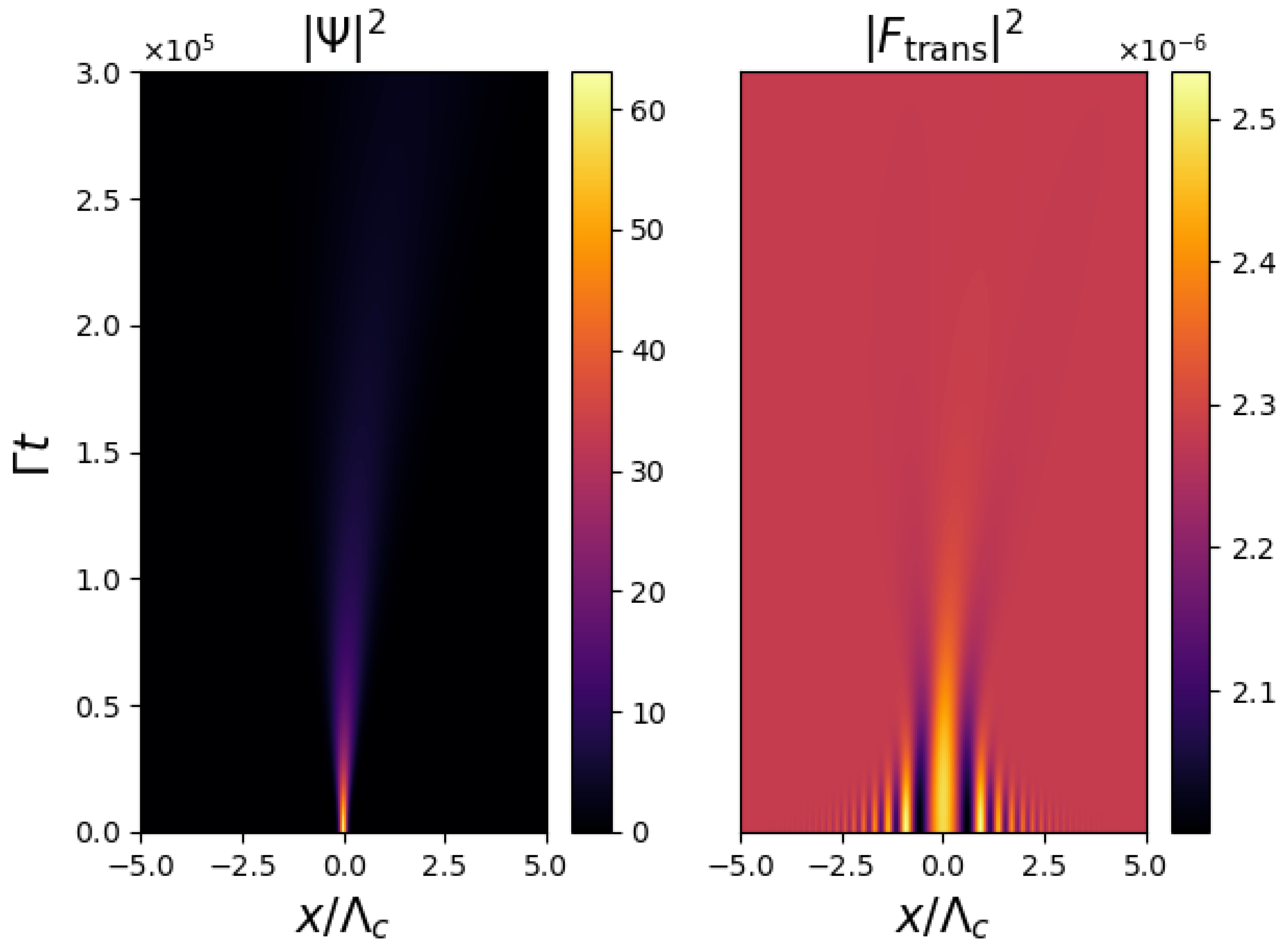
In order to demonstrate the significance of the mirror feedback for the droplet stability, Figure 5 shows the evolution of the system when the mirror feedback is removed, i.e., mirror reflectivity , with all other parameters as those in Figure 3. It can be seen that in the absence of feedback, the droplet rapidly disperses and it is not possible to determine a well-defined trajectory from the similarly dispersing optical intensity distribution. This demonstrates that the mirror feedback is a critically important component of this system, which is required to maintain the soliton-like stability of the droplet and its corresponding optical image.
5. Conclusions
We have demonstrated that the existence of optomechanical droplets in a BEC illuminated by a far off-resonant optical pump field and its retroreflection from a feedback mirror could form the basis of a method to measure the acceleration of a BEC via continuous monitoring of the position of thedroplet via the optical intensity distribution. This differs from previous schemes involving acceleration sensing involving BECs in optical cavities, where the acceleration was calculated via continuous measurements of the Bloch oscillation frequency [13,14,15,16,17,18] from the optical intensity evolution.
It should be noted that although only the motion of single droplet structures has been presented here, stable multi-peak droplet structures can exist [47] and display similar behaviour under acceleration, maintaining their structure as they propagate and providing a consistent optical intensity profile dependent on detuning.
Possible extensions of the study presented here include increasing the interaction time by bouncing the BEC off a potential barrier and considering a spatially non-uniform acceleration of the BEC.
Author Contributions
Simulations—G.R.M.R. and J.G.W.; Analysis—G.R.M.R., J.G.W., G.-L.O. and T.A.; Writing, reviewing and editing—G.R.M.R., G.-L.O. and T.A. All authors have read and agreed to the published version of the manuscript.
Funding
This research received no external funding.
Data Availability Statement
The raw data supporting the conclusions of this article will be made available by the authors on request.
Conflicts of Interest
The authors declare no conflict of interest.
References
- Barratt, B.; Gominet, P.A.; Cantin, E.; Antoni-Micollier, L.; Bertoldi, A.; Battelier, B.; Bouyer, P.; Lautier, J.; Landragin, L. Mobile and remote inertial sensing with atom interferometers. In Proceedings of the Proceedings International School Physics ‘Enrico Fermi’, Varenna, Italy, 30 June–5 July 2014; Volume 188, p. 493. [Google Scholar]
- Kasevich, M.; Chu, S. Measurement of the gravitational acceleration of an atom with a light-pulse atom interferometer. Appl. Phys. B 1992, 54, 321. [Google Scholar] [CrossRef]
- Adams, C.S.; Sigel, M.; Mlynek, J. Atom Optics. Phys. Rep. 1994, 240, 143. [Google Scholar] [CrossRef]
- Peters, A.; Chung, K.Y.; Chu, S. Measurement of gravitational acceleration by dropping atoms. Nature 1999, 400, 849. [Google Scholar] [CrossRef]
- Bloom, A.L. Principles of Operation of the Rubidium Vapor Magnetometer. Appl. Opt. 1962, 1, 61–68. [Google Scholar] [CrossRef]
- Budker, D.; Romalis, M. Optical magnetometry. Nat. Phys. 2007, 3, 227–234. [Google Scholar] [CrossRef]
- Kitching, J.; Knappe, S.; Donley, E.A. Atomic Sensors—A Review. IEEE Sens. 2011, 11, 1749. [Google Scholar] [CrossRef]
- Andrews, M.; Mewes, M.O.; Van Druten, N.; Durfee, D.; Kurn, D.; Ketterle, W. Direct, nondestructive observation of a Bose condensate. Science 1996, 273, 84–87. [Google Scholar] [CrossRef] [PubMed]
- Andrews, M.R.; Kurn, D.; Miesner, H.J.; Durfee, D.S.; Townsend, C.G.; Inouye, S.; Ketterle, W. Propagation of sound in a Bose–Einstein condensate. Phys. Rev. Lett. 1997, 79, 553–556. [Google Scholar] [CrossRef]
- Bradley, C.; Sackett, C.; Hulet, R. Bose–Einstein condensation of lithium: Observation of limited condensate number. Phys. Rev. Lett. 1997, 78, 985–989. [Google Scholar] [CrossRef]
- Stenger, J.; Inouye, S.; Chikkatur, A.P.; Stamper-Kurn, D.M.; Pritchard, D.E.; Ketterle, W. Bragg Spectroscopy of a Bose–Einstein Condensate. Phys. Rev. Lett. 1999, 82, 4569–4573. [Google Scholar] [CrossRef]
- Saba, M.; Pasquini, T.A.; Sanner, C.; Shin, Y.; Ketterle, W.; Pritchard, D.E. Light Scattering to Determine the Relative Phase of Two Bose–Einstein Condensates. Science 2005, 307, 1945–1948. [Google Scholar] [CrossRef]
- Peden, B.M.; Meiser, D.; Chiofalo, M.L.; Holland, M.J. Nondestructive cavity QED probe of Bloch oscillations in a gas of ultracold atoms. Phys. Rev. A 2009, 80, 043803. [Google Scholar] [CrossRef]
- Venkatesh, B.P.; Trupke, M.; Hinds, E.A.; O’Dell, D.H.J. Atomic Bloch-Zener oscillations for sensitive force measurements in a cavity. Phys. Rev. A 2009, 80, 063834. [Google Scholar] [CrossRef]
- Goldwin, J.; Venkatesh, B.P.; O’Dell, D. Backaction-Driven Transport of Bloch Oscillating Atoms in Ring Cavities. Phys. Rev. Lett. 2014, 113, 073003. [Google Scholar] [CrossRef] [PubMed]
- Keßler, H.; Klinder, J.; Venkatesh, B.P.; Georges, C.; Hemmerich, A. In situ observation of optomechanical Bloch oscillations in an optical cavity. New J. Phys. 2016, 18, 102001. [Google Scholar] [CrossRef]
- Samoylova, M.; Piovella, N.; Hunter, D.; Robb, G.R.M.; Bachelard, R.; Courteille, P.W. Mode-locked Bloch oscillations in a ring cavity. Laser Phys. Lett. 2015, 11, 126005. [Google Scholar] [CrossRef]
- Samoylova, M.; Piovella, N.; Robb, G.R.M.; Bachelard, R.; Courteille, P.W. Synchronization of Bloch oscillations by a ring cavity. Opt. Express 2015, 23, 14823. [Google Scholar] [CrossRef] [PubMed]
- Dahan, M.B.; Peik, E.; Reichel, J.; Castin, Y.; Salomon, C. Bloch Oscillations of Atoms in an Optical Potential. Phys. Rev. Lett. 1996, 76, 4508. [Google Scholar] [CrossRef]
- Kruse, D.; von Cube, C.; Zimmermann, C.; Courteille, P.W. Observation of lasing mediated by collective atomic recoil. Phys. Rev. Lett. 2003, 91, 183601. [Google Scholar] [CrossRef]
- Ritsch, H.; Domokos, P.; Brennecke, F.; Esslinger, T. Cold atoms in cavity-generated dynamical optical potentials. Rev. Mod. Phys. 2013, 85, 553–601. [Google Scholar] [CrossRef]
- Mivehvar, F.; Piazza, F.; Donner, T.; Ritsch, H. Cavity QED with quantum gases: New paradigms in many-body physics. Adv. Phys. 2021, 70, 1–153. [Google Scholar] [CrossRef]
- Kollar, A.J.; Papageorge, A.T.; Vaidya, V.D.; Guo, Y.; Keeling, J.; Lev, B.L. Supermode-density-wave-polariton condensation with a Bose–Einstein condensate in a multimode cavity. Nat. Commun. 2017, 8, 14386. [Google Scholar] [CrossRef]
- Kroeze, R.M.; Guo, Y.; Vaidya, V.D.; Keeling, J.; Lev, B.L. Spinor self-ordering of a quantum gas in a cavity. Phys. Rev. Lett. 2018, 121, 163601. [Google Scholar] [CrossRef] [PubMed]
- Guo, Y.; Kroeze, R.M.; Marsh, B.P.; Gopalakrishnan, S.; Keeling, J.; Lev, B.L. An optical lattice with sound. Nature 2021, 599, 211. [Google Scholar] [CrossRef] [PubMed]
- Cross, M.C.; Hohenberg, P.C. Pattern formation outside of equilibrium. Rev. Mod. Phys. 1993, 65, 851. [Google Scholar] [CrossRef]
- Grynberg, G.; Le Bihan, E.; Verkerk, P.; Simoneau, P.; Leite, J.R.; Bloch, D.; Le Boiteux, S.; Ducloy, M. Observation of instabilities due to mirrorless four-wave mixing oscillation in sodium. Opt. Commun. 1988, 67, 363–366. [Google Scholar] [CrossRef]
- Lippi, G.; Ackemann, T.; Hoffer, L.; Lange, W. Transverse structures in a sodium-filled Fabry-Pérot resonator—I. Experimental results: Symmetries and the role of the incoupling conditions. Chaos Solitons Fractals 1994, 4, 1409–1431. [Google Scholar] [CrossRef]
- Lippi, G.; Ackemann, T.; Hoffer, L.; Lange, W. Transverse structures in a sodium-filled Fabry-Pérot resonator—II. Interpretation of experimental results. Chaos Solitons Fractals 1994, 4, 1433–1449. [Google Scholar] [CrossRef]
- Giusfredi, G.; Valley, J.; Pon, R.; Khitrova, G.; Gibbs, H. Optical instabilities in sodium vapor. JOSA B 1988, 5, 1181–1192. [Google Scholar] [CrossRef]
- Firth, W. Spatial instabilities in a Kerr medium with single feedback mirror. J. Mod. Opt. 1990, 37, 151–153. [Google Scholar] [CrossRef]
- Arecchi, F.T.; Boccaletti, S.; Ramazza, P.L. Pattern formation and competition in nonlinear optics. Phys. Rep. 1999, 318, 1–83. [Google Scholar] [CrossRef]
- Lugiato, L.A. Transverse nonlinear optics: Introduction and review (Editorial to special issue: Nonlinear optical structures, patterns, chaos). Chaos Solitons Fractals 1994, 4, 1251–1258. [Google Scholar] [CrossRef]
- Rosanov, N.N. Transverse patterns in wide-aperture nonlinear optical systems. Prog. Opt. 1996, 35, 1–60. [Google Scholar]
- Barbay, S.; Kuszelewicz, R.; Tredicce, J.R. Cavity Solitons in VCSEL Devices. Adv. Opt. Tech. 2011, 2011, 628761. [Google Scholar] [CrossRef]
- Grynberg, G.; Maître, A.; Petrossian, A. Flowerlike patterns generated by a laser beam transmitted through a rubidium cell with a single feedback mirror. Phys. Rev. Lett. 1994, 72, 2379–2382. [Google Scholar] [CrossRef] [PubMed]
- Ackemann, T.; Lange, W. Non- and nearly hexagonal patterns in sodium vapor generated by single-mirror feedback. Phys. Rev. A 1994, 50, R4468–R4471. [Google Scholar] [CrossRef] [PubMed]
- Ackemann, T.; Lange, W. Optical pattern formation in alkali metal vapors: Mechanisms, phenomena and use. Appl. Phys. B 2001, 72, 21–34. [Google Scholar] [CrossRef]
- Greenberg, J.A.; Schmittberger, B.L.; Gauthier, D. Bunching-induced optical nonlinearity and instability in cold atoms. Opt. Exp. 2011, 19, 22535. [Google Scholar] [CrossRef] [PubMed]
- Schmittberger, B.L.; Gauthier, D.J. Spontaneous emergence of free-space optical and atomic patterns. New J. Phys. 2016, 18, 10302. [Google Scholar] [CrossRef]
- Labeyrie, G.; Tesio, E.; Gomes, P.M.; Oppo, G.L.; Firth, W.J.; Robb, G.R.; Arnold, A.S.; Kaiser, R.; Ackemann, T. Optomechanical self-structuring in a cold atomic gas. Nat. Photonics 2014, 8, 321–325. [Google Scholar] [CrossRef]
- Tesio, E. Theory of Self-Organisation in Cold Atoms. Ph.D. Thesis, University of Strathclyde, Glasgow, UK, 2014. [Google Scholar]
- Firth, W.J.; Krešić, I.; Labeyrie, G.; Camara, A.; Ackemann, T. Thick-medium model of transverse pattern formation in optically excited cold two-level atoms with a feedback mirror. Phys. Rev. A 2017, 96, 053806. [Google Scholar] [CrossRef]
- Robb, G.; Tesio, E.; Oppo, G.L.; Firth, W.; Ackemann, T.; Bonifacio, R. Quantum threshold for optomechanical self-structuring in a Bose–Einstein condensate. Phys. Rev. Lett. 2015, 114, 173903. [Google Scholar] [CrossRef]
- Zhang, Y.C.; Walther, V.; Pohl, T. Long-range interactions and symmetry breaking in quantum gases through optical feedback. Phys. Rev. Lett. 2018, 121, 073604. [Google Scholar] [CrossRef]
- Zhang, Y.C.; Walther, V.; Pohl, T. Self-bound droplet clusters in laser-driven Bose–Einstein condensates. Phys. Rev. A 2021, 103, 023308. [Google Scholar] [CrossRef]
- Walker, J.G.M.; Robb, G.R.M.; Oppo, G.L.; Ackemann, T. Dynamics of optomechanical droplets in a Bose–Einstein condensate. Phys. Rev. A 2022, 105, 063305. [Google Scholar] [CrossRef]
- Edmonds, M.; Bland, T.; Parker, N. Quantum droplets of quasi-one-dimensional dipolar Bose–Einstein condensates. J. Phys. Commun. 2020, 4, 125008. [Google Scholar] [CrossRef]
- Cabrera, C.R.; Tanzi, L.; Sanz, J.; Naylor, B.; Thomas, P.; Cheiney, P.; Tarruell, L. Quantum liquid droplets in a mixture of Bose–Einstein condensates. Science 2018, 359, 301–304. [Google Scholar] [CrossRef]
- Ackemann, T.; Firth, W.; Oppo, G.L. Fundamentals and applications of spatial dissipative solitons in photonic devices. Adv. At. Mol. Opt. Phys. 2009, 57, 323–421. [Google Scholar]
- von Cube, C.; Slama, S.; Kruse, D.; Zimmermann, C.; Courteille, P.W.; Robb, G.R.M.; Piovella, N.; Bonifacio, R. Self-Synchronization and Dissipation-Induced Threshold in Collective Atomic Recoil Lasing. Phys. Rev. Lett. 2004, 93, 083601. [Google Scholar] [CrossRef] [PubMed]
- Baumann, K.; Guerlin, C.; Brennecke, F.; Esslinger, T. Dicke quantum phase transition with a superfluid gas in an optical cavity. Nature 2010, 464, 1301–1306. [Google Scholar] [CrossRef]
- Ferrier-Barbut, I.; Kadau, H.; Schmitt, M.; Wenzel, M.; Pfau, T. Observation of Quantum Droplets in a Strongly Dipolar Bose Gas. Phys. Rev. Lett. 2016, 116, 215301. [Google Scholar] [CrossRef] [PubMed]
- Chomaz, L.; Baier, S.; Petter, D.; Mark, M.J.; Wachtler, F.; Santos, L.; Ferlaino, F. Quantum-Fluctuation-Driven Crossover from a Dilute Bose–Einstein Condensate to a Macrodroplet in a Dipolar Quantum Fluid. Phys. Rev. X 2016, 6, 041039. [Google Scholar] [CrossRef]
- Goldberg, A.; Schwartz, J.L. Integration of the Schrödinger equation in imaginary time. J. Comput. Phys. 1967, 1, 433–447. [Google Scholar] [CrossRef]
- Robb, G.; Walker, J.; Oppo, G.L.; Ackemann, T. Long-range interactions in a quantum gas mediated by diffracted light. Phys. Rev. Res. 2023, 5, L032004. [Google Scholar] [CrossRef]
- Plestid, R.; O’Dell, D. Balancing long-range interactions and quantum pressure. Phys. Rev. E 2019, 100, 022216. [Google Scholar] [CrossRef] [PubMed]
Figure 1.
Schematic diagram of the single mirror feedback (SMF) configuration showing a BEC interacting with a forward propagating optical field (F) and a retroreflected/backward propagating optical field (B) while undergoing an acceleration (a) in the direction. The optical image of the BEC is detected after transmission through the BEC, propagation in free space to a mirror of reflectivity, R, at a distance d from the BEC, and further propagation over distance d.

Figure 2.
Evolution of the BEC density, , and optical intensity at the image plane, , calculated from the BEC–SMF model, Equations (1)–(3), using an initial condition where the BEC density is a Gaussian function of position with width . Parameters used are , , , and .

Figure 3.
Evolution of the BEC density, , and optical intensity at the image plane, , calculated from the accelerating BEC–SMF model, Equation (2), (3) and (8), showing a uniformly accelerating droplet. Parameters used are identical those in Figure 2 with the exception of the acceleration parameter, which here is .

Figure 4.
Plot of position of central optical intensity maximum, , against from Figure 3.
Figure 4.
Plot of position of central optical intensity maximum, , against from Figure 3.


Disclaimer/Publisher’s Note: The statements, opinions and data contained in all publications are solely those of the individual author(s) and contributor(s) and not of MDPI and/or the editor(s). MDPI and/or the editor(s) disclaim responsibility for any injury to people or property resulting from any ideas, methods, instructions or products referred to in the content. |
© 2024 by the authors. Licensee MDPI, Basel, Switzerland. This article is an open access article distributed under the terms and conditions of the Creative Commons Attribution (CC BY) license (https://creativecommons.org/licenses/by/4.0/).
Share and Cite
MDPI and ACS Style
Robb, G.R.M.; Walker, J.G.; Oppo, G.-L.; Ackemann, T. Continuous Acceleration Sensing Using Optomechanical Droplets. Atoms 2024, 12, 15. https://doi.org/10.3390/atoms12030015
AMA Style
Robb GRM, Walker JG, Oppo G-L, Ackemann T. Continuous Acceleration Sensing Using Optomechanical Droplets. Atoms. 2024; 12(3):15. https://doi.org/10.3390/atoms12030015
Chicago/Turabian StyleRobb, Gordon R. M., Josh G. Walker, Gian-Luca Oppo, and Thorsten Ackemann. 2024. "Continuous Acceleration Sensing Using Optomechanical Droplets" Atoms 12, no. 3: 15. https://doi.org/10.3390/atoms12030015
Note that from the first issue of 2016, this journal uses article numbers instead of page numbers. See further details here.