The Heuristic of Directional Qualitative Semantic: A New Heuristic for Making Decisions about Spinning with Qualitative Reasoning


Grupo de Investigación en Minería de Datos (MiDa), Universidad de Salamanca, 37008 Salamanca, Spain
Robotics 2021, 10(1), 17; https://doi.org/10.3390/robotics10010017
Submission received: 30 November 2020
/
Revised: 10 January 2021
/
Accepted: 12 January 2021
/
Published: 15 January 2021
(This article belongs to the Special Issue Robotics and AI)
Abstract
:Multifunctional Robot On Topological Notions (MROTN) is a research program that has as one of its goals to develop qualitative algorithms that make navigation decisions. This article presents new research from MROTN that extends previous results by allowing an agent to carry out qualitative reasoning about direction and spinning. The main result is a new heuristic, the Heuristic of Directional Qualitative Semantic (HDQS), which allows for selecting a spinning action to establish a directional relation between an agent and an object. The HDQS is based on the key idea of encoding directional information into topological relations. The new heuristic is important to the MROTN because it permits the continued development of qualitative navigation methods based on topological notions. We show this by presenting a new version of the Topological Qualitative Architecture of Navigation that uses the HDQS to address situations that require spinning.
1. Introduction
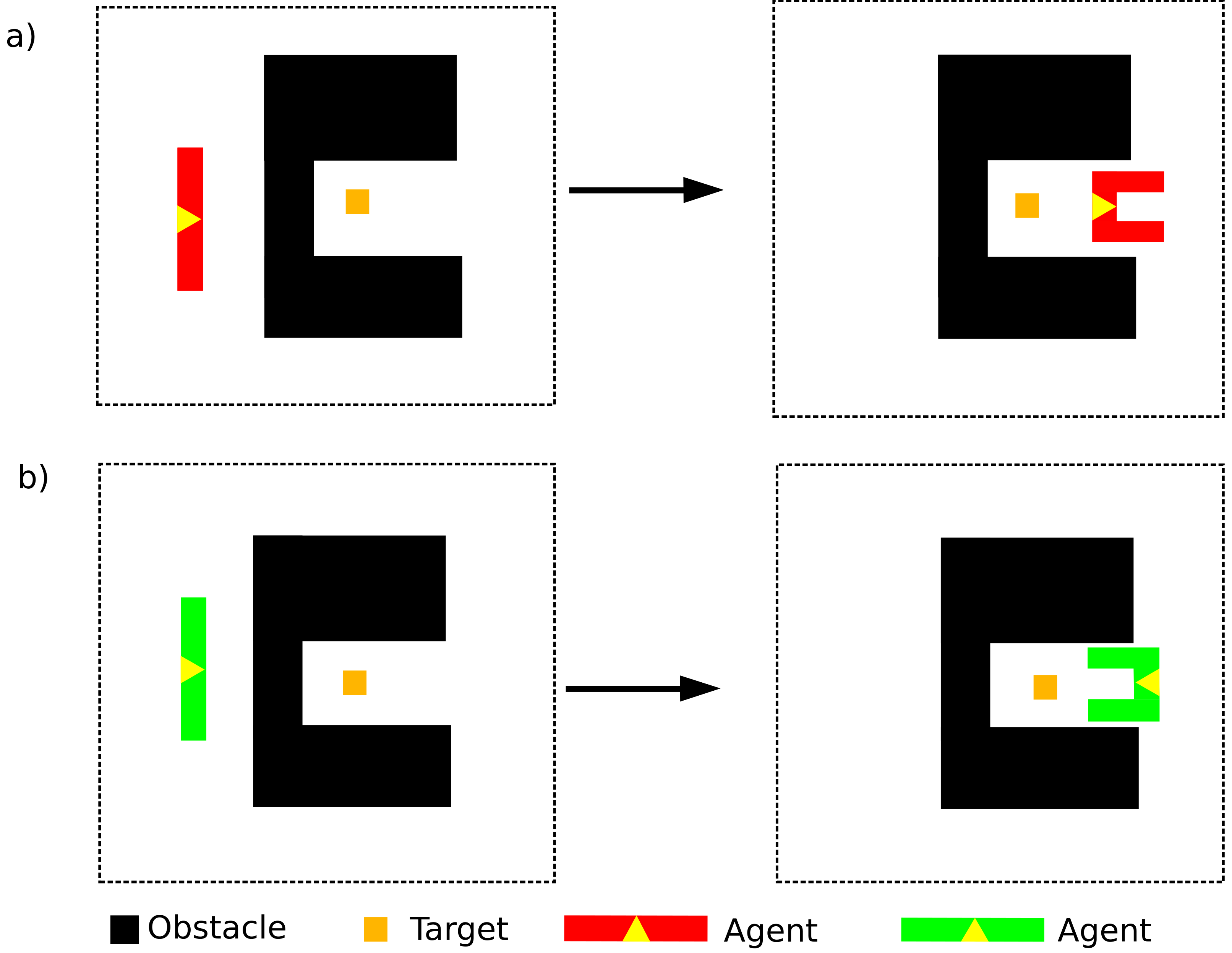
In robotics, there are two approaches to each task: quantitative and qualitative. One of the advantages of using quantitative methods is that the information obtained by the sensors available to a robot (bumpers, sonars, lasers, etc.) can be directly expressed in a geometric representation of space. However, quantitative methods have an important disadvantage because they lack sufficient expressivity to allow a mobile robot to perform tasks which go beyond mere movement from one spatial point to another. This is a problem, given that human beings mainly make use of relationships between spatial areas to communicate tasks and information. For this reason, the development of qualitative methods is essential to attain multifunctional robots capable of continuous interaction in social environments. This paper presents new results obtained in a program, called Multifunctional Robot On Topological Notions (MROTN), initiated to research the use of topological notions to represent qualitative spatial relations and to apply these notions to produce multifunctional robots [1,2,3,4]. These new results extend the previous results of the MROTN program. Specifically, they address the limitations of the Heuristic of Topological Qualitative Semantic (HTQS) [1,2]. The initial investigation that led to the HTQS was done considering an agent which could move backwards, forwards, left, and right. In a previous paper, it is explained how HTQS can be used to achieve navigation in unknown and dynamic environments [3]. However, the set of actions that includes moving backwards, forwards, left, and right does not allow for all possible configurations for an agent because it does not permit a change of orientation. However, the set of actions that includes spinning and moving backwards and forwards allows for all possible configurations because left and right movements can be built together with backwards, forward, and spinning movements. Figure 1 shows an example of the limitation of an agent that does not have spinning in its set of movements and compares it with one that does.
For these reasons, many domestic robots are only equipped with mechanisms to spin and move backwards and forwards. As a result, research has been carried out to create methods for robots to reason about spinning and select which spinning actions to apply.
Qualitative reasoning about direction has been researched in the fields of cartography and geographical information systems (GISs). The main problem in GISs research is how to deduce the direction from point A to point C, given the directions from A to B and B to C [5]. Different proposals to resolve that problem have been made, such as a projection-based concept [5], cone-shaped directions [5,6], double cross calculus [7], cardinal direction calculus (CDC) [8], flip-flop [9], dipole [10], Oriented Point Relation Algebra [11], and TPCC [12]. These proposals address the problem of identifying which is being designated among a group of objects when given a set of relational directions. In robotics, different methods have been used to address planning routes with qualitative directions, such as extended double cross [13], the line of moving direction [14], and cone-shaped directions [15]. However, making decisions about directions in local navigation is done using mostly quantitative directions [16,17,18], and little research has been done on qualitative reasoning about orientation. One proposal to carry out qualitative reasoning about orientation and spinning for agents is based on with adjustable granularity [19]. Other proposals include the use of a topological-semantic-metric (TSM) map [14] and the Qualitative Trajectory Calculus Double-Cross [20].
The research presented in this article (which is based on one section of a chapter of the author’s PhD thesis [21]) focuses on making qualitative decisions about spinning in local navigation. This is an important topic because the natural way humans communicate spatial tasks is by making use of spatial relations. For example, we use qualitative language to communicate information, such as “Turn around and face the cathedral”. Given this, it would seem necessary for a multifunctional robot capable of functioning in human environments to possess a high degree of spatial reasoning, and, specifically, reasoning about qualitative spatial relations. The ability of a robot to move around and interact in an urban environment depends on the capacity to perform tasks such as capturing the environment, self-localization, navigation, planning and natural language processing [1]. Most approaches to address qualitative directional information are based on points as the basic entities for describing the cardinal direction. The approach presented here to describe qualitative directional information is novel because it incorporates qualitative topological relationships to determine direction. Specifically, the qualitative topological relationships are the set of relative topological relations [1,2]. In addition, the process to make decisions presented here differs from previous research in that it is a qualitative heuristic. The new contributions contained in this article are based on the key idea of encoding directional information into relative topological relations.
Establishing a direction is an important feature that allows addressing different issues related to navigation in dynamic and unknown environments. In a dynamic environment, if the agent leaves an object behind while moving forward, it cannot move backwards to find the object again because the environment could have changed and it could crash into an obstacle, so it requires spinning to register the environment while it turns back. Another important issue is that if an agent needs to go to a specific position while it is exploring an unknown environment, it could be advantageous to perform diagonals, which requires spinning and establishing a qualitative direction. This paper’s main result is a new heuristic that establishes a qualitative direction, and it opens the door to creating agents that perform qualitative navigation by making diagonals and turning back to previous positions.
An additional motivation of this research is designing an architecture in agreement with the Cognitive Theory of True Conditions (CTTC). The essence of the CTTC is that true conditions not only give meaning to language expression but also play a fundamental role in all the cognitive processes of the human brain [22,23]. The previous architecture, TQNA 1.0 [3], lacks true conditions to describe an agent’s spinning actions. This paper presents a new version of the TQNA that uses a new heuristic to assign true conditions to the classify the spinning actions and establish changes in orientation.
The structure of the article as follows. Section 2 briefly reviews how the MROTN program addresses the navigation tasks and summarizes its results to date. Section 3 presents research we conducted about spinning decisions and the heuristic we found. Section 4 provides an overview of how we have tested the heuristic, and Section 5 presents how it has been incorporated into TQNA 2.0. Section 6 discusses the achieved results and future research plans. The last section summarizes the achieved results.
2. The Research Program: Multifunctional Robot on Topological Notions
The MROTN program proposes using spatial relations based on topological notions to research navigation problems [1,2]. One of the main results of the MROTN is HTQS. HTQS can only be used in open spaces because it does not allow for making decisions about spinning. Before presenting the research about how qualitative topological notions can be used to make decisions about spinning, we review HTQS.
HTQS finds a solution to the problem of topological qualitative navigation [1,2]. The fundamental element of HTQS is the topological reasoning linear graph (TRLG), which is a tuple whose elements are relative topological relations (RTRs). The set of RTRs concerning has 13 elements. Thus, , , , , , , , , , , , , where is called Disjoint-0, is called Meet-0, is called Overlap-0, is called CoveredBy-0, is called Covers-0, is called Inside, is called Equal, is called Contains, is called CoveredBy-1, is called Covers-1, is called Overlap-1, is called Meet-1, and is called Disjoint-1. The visualization of the RTRs can be observed in Figure 2:
The relative topological relations are calculated in by means of the formalism order propositions matrix and denoted by consisting of the following matrix:
where X is the region occupied in by the agent and Y is the region occupied also in by the object or the target.
Each of the elements of the matrix is a proposition that has a value of , depending on whether the proposition is false (0) or true (1). Table 1 shows the characterization of each of the relative topological relations by the order propositions matrix.
The HTQS requires the following data structures for its implementation:
- A table with the agent’s actions labeled by one of the three following relations: . The meaning of the labels depends on the kind of the reference system that represents the position of the space. For example, if it is egocentric, < means that the action causes the values of the objects to increase after it is applied, = means that the action does not cause a change in the values of the objects after it is applied, and > means that the action causes the values of the objects to decrease after it is applied.
- A set of rules to assign the corresponding TRLG to each agent and object.
For an order topology on a non-dense space, the set of rules used to assign the corresponding TRLG to the agent and object is relative to their size and shape in Table 2.
Devices that capture information for robots are physically constrained and have a finite number of sensors. Therefore, the set of rules used for an HTQS-compliant robot should be of an order topology with non-dense space, for example . It is true that, if the sensitivity of the robot’s sensors is sufficiently high, the subcases arising from the characteristics of a non-dense space cannot happen easily.
The implementation of the HTQS comprises the following steps:
- A TRLG is selected according to the size of the objects and .
- The relative topological relation between the objects and is calculated from their current positions, , and the number associated with the node of in the TRLG, , is stored.
- The number, , associated with the node of the relative topological relation that is the target between the objects and , , is obtained.
- It is checked which order relation holds between and from the following:The definitions of the relations must agree with the labeling of actions.
- It is examined at the means-ends table using the order relation that holds between and in order to select the action that is labeled with the same order relation. This is the action selected by heuristics.
3. Qualitative Reasoning about Orientation and Spinning
The research presented in this paper has addressed a kind of navigation problem that consists in using the quantitative sensory spatial information an agent’s sensor registers to choose a spinning action that establishes a specific directional relation with a specific object. Specifically, the problem has two goals to solve. The first goal is starting from a quantitative description of the agent’s spatial environment and generating a set of jointly exhaustive and pairwise disjoint binary relations that describe the directions so that two objects of the environment are always in one and only one of the relations of the set. The second goal is obtaining a method with low computational complexity that selects from the actions an agent can perform those that can establish a directional relation between the agent and an object based on the initial relation that describes the object’s direction with reference to the agent.
Considering the information above, we can define a type of general problem, which is called directional problem based on spatial relations and is expressed as follows:
Givinga starting spatial configuration that contain a list of objectsof which one is a robot, the robot must establish the spatial relationsamong objectsby using [the robot’s] knowledge and sensory information received.
where, and , reference specific objects of the environment.
In this article, we focus on a specific problem subtype of the directional problem based on spatial relations in which the following constraints are fixed:
- A is a region of the Euclidean space .
- The environment has only two objects: a motionless object and an agent.
- The agent has two actions: spinning left and right.
It must be noted that the problem addressed in this paper in which the agent starts from a quantitative description of the environment poses a type of problem a real robot can face. A robot obtains quantitative spatial information by sensors, such as a robot sonar [24], laser ranging [25] or an artificial vision system [26]. Thus, the methods presented here, in addition to solving the problem based on spatial relations we have posed, could be usable in real-world applications.
We followed these steps to address this problem: (1) We established a general instance of the problem and analyzed how to extract qualitative directional information from it. (2) We formulated a model to describe qualitative directional information. (3) We created a heuristic that solves the problem of making decisions about spinning using the formulated model. (4) We tested the solution by creating a computer program. (5) We applied the solution to improve a navigation architecture. In this section and the following ones, we describe these steps and their results.
3.1. Initial Assumptions
The research conducted for the present article considered a two-dimensional Euclidian space as a workspace, resulting in two possible actions: spinning left and spinning right. Additionally, some assumptions were made relative to the objects and agents to focus the research on concrete situations. For this research, each situation considered fulfills the following four conditions:
- The two-dimensional space has a Euclidean geometry. This geometry describes the physical space of our daily life.
- The agent is symmetrical, and its rotating point is the center of mass, considering the agent would have its mass distributed uniformly. This assumption is assumed because most robots have a symmetric shape, and even humans and many other animals are symmetric.
- If the object is concave, it is not surrounding the agent fully or partially. This is assumed because if an object is surrounding the agent, the concept of the direction of the object has lost its meaning and we cannot assign a direction. Therefore, the agent cannot be inside one of the cavities of another object. Because an agent in a cavity is surrounded by the object, we cannot discuss directional relation between the agent and the object. Figure 3 gives two examples of situations in which direction does and does not make sense. Instead, an agent surrounded by an object should be represented through a topological relation, as discussed in a previous article [27].
- The agent cannot collide with the object while spinning. It implies that the shortest distance from the object to the agent’s rotation point is greater than the distance from the farthest point from the agent to its rotation point.
Because this work is focused on describing relative orientations, the last assumption was that the object and the agent never overlap when the agent is spinning. Thus, the issue of detecting collisions while spinning is outside the scope of this paper.
3.2. Transforming Directional Information into Topological Information
The first element of a heuristic is a representation of the possible qualitative states of the problem. The HTQS uses a qualitative coordinate system to represent the states, which can be understood as a Cartesian qualitative coordinate system because the set of actions used to change from one’s coordinates to another’s are backwards, forwards, left, and right. However, if we want to use spinning, a different kind of qualitative coordinate system is needed to make the decisions. The research begins by noting the next two facts:
- An agent with continuous symmetry does not modify the agent’s spatial position when it spins.
- Spinning actions modify the direction between an agent and an object, even if the agent has a continuous symmetry.
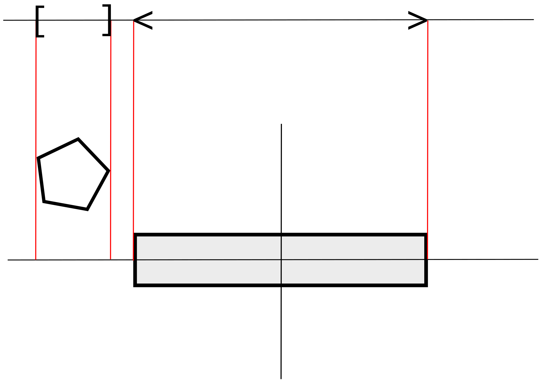
Using the above facts, we deduce that we cannot use only topological information to make decisions about spinning and that directional information is essential to reasoning about spinning. Therefore, we explored encoding directional information into a topological representation. Given that the relative direction between an agent and an object is altered when the agent spins, the goal was to develop a method that expresses how and in which direction the two objects are aligned. The method found to represent the alignment consists of projecting the object and the agent in a one-dimensional space that is parallel to the x-axis of the egocentric coordinate system fixed in the agent’s point of rotation. The orientation of the coordinate systems uses the forward direction of the agent as the y-axis. Once the projections are obtained, the relative topological relation between the projections of the agent and the object are calculated. This idea is shown in Figure 4. The agent in Figure 4 does not have continuous symmetry because a rectangular shape allows for showing spinning changes better, but the method also works with objects with continuous symmetry.
The agent’s sensors record quantitative information, and the agent can represent this information using an egocentric coordinate system. The vertical axis of the egocentric coordinate system corresponds with the direction in which the agent can move forwards and backwards. The origin of the coordinates is the agent’s point of rotation, and the vertical and horizontal axes are orthogonal. Therefore, the method used to calculate the projection is taking the x-coordinates of the object and the agent of the egocentric coordinate system. The coordinate system must be egocentric because it permits knowledge of the alignment caused by the spinning motion of the agent. If the system of reference were allocentric, the coordinates and the coordinate axes would be static, and the object would hold the same values independent from the spinning motion of the agent. Therefore, no change could be registered because the origin of the projection would be always the same. The egocentric and allocentric cases can be seen in Figure 5.
The projection permits the identification of a topological relation that encodes directional information relative to the object and the agent. However, because the projection goes from a two-dimensional space to a one-dimensional space, there is some information that disappears. That loss of information can be seen in Figure 6. The projection provides information about the alignment, but it is not possible to know in which direction the alignment occurs.
Although in this work we do not consider actions aside from spinning, the information lost is essential for choosing between backwards and forwards actions, so it must be incorporated. To achieve that goal, the guiding idea was creating positional variants of the relative topological relations. This idea was specified by creating three positional variants of each relative topological relation. Each positional variant contains information about the direction from which the projection was done. Those variants are denoted by: . Each is associated with a region of the space. The positional variants come from the division of the two-dimensional space into three regions and − where the object projection occurs. These three regions are relative to the agent because the coordinate system is egocentric. The two-dimensional space is divided, drawing two straight lines parallel to the x-axis: one through the point of the agent with a greater y-coordinate and the other through the agent’s point with a lesser y-coordinate. These divisions of the space produce three regions, and each region is associated with one of the three variants. Two examples of the three regions are shown in Figure 7.
The positional variants form a set, . Using the sets (see Section 2) and , a new set of relations is defined in the following way:
Each element of the set of relations is called a directional topological relation (DTR).
To simplify the notation of the directional topological relations, the pair that denotes the relation is substituted by the relative topological relation with a superindex, which is the symbol of the variant, for example
The assignment of the positional variant to the relation comes from which region the object is projected. The rule for assigning a positional variant is that, if the object is completely inside + or −, those will be the variants assigned, but, if any part of the object is in the = area, then the relation will be assigned the variant =. This method solves the problem of lost directional information, as shown in Figure 8.
The steps to calculate the DTR between an agent and an object are shown in Algorithm 1. The data used in Algorithm 1 are described graphically in Figure 9.
| Algorithm 1 Algorithm to calculate the Directional Topological Relation (DTR). |
| Ensure: Directional Topological Relation. |
|
3.3. Heuristic of Directional Qualitative Semantic
As stated above, an agent has two directions for spinning, and even an agent with one spinning action can establish any directional topological relation with an object because it is cyclic. Therefore, establishing any directional topological relation with an object can always be resolved using the same spinning action. This leads to the generation of a goal for the heuristic to not only establish a relation with an object but also choose the spinning action that uses less time and energy to establish it. To achieve that goal, a structure that organizes the representations which determine the effects of the decisions is necessary. A total order structure allows for the establishment of a heuristic about actions and their effects. Unlike relative topological relations, directional topological relations cannot be organized as a total order structure. This is not possible because, after an agent spins 360 degrees, it will still be in the same relation with the object. Thus, the structure selected to organize directional topological relations is a cycle graph. The nodes of the cycle graph are elements of . This cycle graph is named Directional Topological Reasoning Graph (DTRG). The edges of a DTRG lead from the current DTR between an agent and an object to the previous or following DTR when the agent is spinning. The direction of the edges matches the direction of the spinning. In turn, the cycle graph must respect a cyclic order. A cyclic order is a ternary relation that satisfies cyclicity, asymmetry, transitivity, and totality. Those properties imply that the cyclic order arranges a set of objects in a circle. Thus, C is a cyclic order, if the following is fulfilled:
To denote a cyclic order, we use the following general notation:
We switch the common position of the parentheses (mimicking links of a chain that must be united) to denote that it is a cyclic relation where the first and the last elements are related.
Similar to TRLGs, DTRGs are made according to the relationship between the size of the agent and the object. The angle of spinning is a real parameter. This differs from the situation about discrete movements that has been studied [1,2]. In the discrete case, there are six different situations caused by the discreteness. The continuity of the parameter angle reduces the number of cases to three. However, the position in the space of the object with regard to the agent causes a different positional variant to be assigned. The conditions cited in Section 3.1 also determine which directional topological reasoning can and cannot occur. Assuming Euclidian geometry, while there is a DTRG that has , there is not any DTRG that has or as one of its nodes. Some DTRGs cannot exist because of the condition that the agent is not able to collide with the spinning object. Thus, assuming that the agent is bigger than the object, the following DTRG is not possible:
This DTRG cannot exist because the DTR between an object and an agent cannot change in a Euclidean space from to since that modification cannot occur without the agent’s spinning causing the object and the agent to collide.
Assuming that the object is bigger than the agent, the following DTRG is also not possible:
The reason is because if the object is not surrounding the agent, the RTR between an object and an agent cannot change from to directly, or from to among other cases.
There are many DTRGs that are not possible, but there are 15 that can exist if the conditions cited in the text are fulfilled. Initially, there are three main cases to consider: the projection of the object in the agent’s horizontal axis is bigger than, equal to, or smaller than the agent. We denote them as: , , and . Each one of those cases has different variants, because of the object’s position, that cause different positional variants. We add a subindex to denote these variants of the main cases. Table 3 shows the 15 possible DTRGs. When the agent is smaller than the target, the number of DTRGs is greater than when the agent is bigger than the target, which can be seen in Table 3, because the agent and the target cannot have shapes and locations that generate the relations or without breaching the conditions set out in this investigation to avoid collisions.
Figure 10 presents a graphical representation of a DTRG that shows .
To achieve the shortest path, the agent must identify the correct DTRG to make decisions about spinning. Identifying the correct DTRG requires the sizes of the agent and the object, but the maximum size in the two-dimensional space is not necessary (as it is in the TRLGs) because the maximum size of the projection depends on the orientation between the agent and the object. The next subsection is dedicated to discussing the method of selecting the correct DTRG.
Considering we have the correct DTRG, an agent has two spinning actions, and . spins to the left and spins to the right. The heuristic must select which action takes less time. To do so, each node of the DTRG must be labeled with a natural number. The labeling assigns 1 to any of the nodes of the DTRG and travelling in the same direction assigns a number to each node visited, increasing one unit from the number assigned to last node. The label of one node will be determined by the function . Figure 10 shows the labeling of one DTRG. In addition, each of the agent’s spinning actions is labeled with a direction that matches the direction that the change of DTR takes when the spinning action is applied. Thus, is labeled with ↶ and with ↷. The next step consists of calculating the distance in both directions from the current node to the wanted node in the DTRG, and, thus, selecting the direction that provides a shorter distance. The distances are calculated as follows:
where is the current node, is the wanted node, is the cardinality of the set of nodes of the DTRG, and is the absolute value of the subtraction indicated.
Once the distances have been calculated, Table a in Figure 11 is used to retrieve a direction label, and the result is then used to select the spinning action using Table b in Figure 11.
Note that, if , then the directional topological relation has been established.
The heuristic explained above, which we named the Heuristic of Directional Qualitative Semantic (HDQS), is condensed in Algorithm 2.
| Algorithm 2 Heuristic of Directional Qualitative Semantic (HDQS). |
| Ensure: A sequence of actions to establish a DTR. |
|
3.4. Selecting a Directional Topological Reasoning Graph
The previous subsection briefly mentions the step for selecting the correct DTRG. Selecting the correct DTRG is complex because an agent that registers information from only the visual system cannot know the maximum length of the projection of some objects because their shapes cause parts of their shapes to be hidden in some positions from the agent’s visual system. If the agent does not know the size of the object, then it does not know what DTR will and will not happen when it spins. Selecting the right DTRG using the visual information is a dead end because there is not enough information, and the problem of how the agent can acquire enough information to select the right DTRG must be addressed.
The proposed solution requires specific physical structures for the agent. The agent must possess a “neck” mechanism that allows for spinning its visual system while the rest of the agent remains fixed. This idea is inspired by biology; we can find this kind of structure in many animals whose necks allow them to spin their visual system. Spinning its visual system alone would use much less energy than spinning the full agent and would avoid unnecessary problems with stability. This action makes it possible to acquire information about the correct DTRG without spinning the full agent in the following way. When the agent spins its visual system, the agent registers which DTRs are being established. There are some DTRs that only exist only in one of the DTRGs, so the agent spins its visual system until it finds a DTR that is in only one DTRG. The system for naming the DTRGs establishes three main cases and the variants of each of these cases. The superindex determines the case, and the subindex determines the variant of the case (see Table 2). We represent the unknown DTRG as . The DTRs have two components: the first is an RTR (see Section 2) and the second a positional variant. The case can be determined by detecting an RTR that differentiates one case from another. We call these relations key RTRs. The key RTRs that determine the case DTRG are the following:
- , , or determine .
- determines .
- , , or determine .
Once the case is set, the variant can be determined by detecting two DTRs. We name a pair of DTRs that allows determining a variant as a key DTR pair.
Therefore, the algorithm to determine the has two main steps. First, the agent spins its visual system until it finds a key RTR with the object that determines the □ of the . The spinning direction of the visual system needed to find a key DTR depends on the initial DTR between the object and the agent. If the visual system has 360-degree vision and the initial DTR is not a key DTR, the algorithm to spin it consists of the four following rules:
- If the positional variant is + or ≈, and the relative topological relation is Disjoint-0, Meet-0, or Overlap-0, the visual system spins to the left.
- If the positional variant is + or ≈, and the relative topological relation is Overlap-1, Meet-1, or Disjoint-1, the visual system spins to the right.
- If the positional variant is −, and the relative topological relation is Disjoint-0, Meet-0, or Overlap-0, the visual system spins to the right.
- If the positional variant is +, and the relative topological relation is Overlap-1, Meet-1, or Disjoint-1, the visual system spins to the left.
If the visual system only has 180-degree vision, the paths to find a key relative topological relation will be longer in the cases where the positional variant is −, and the agent will use the following rules:
- If the positional variant is +, ≈, or −, and the relative topological relation is Disjoint-0, Meet-0, or Overlap-0, the visual system spins to the left.
- If the positional variant is +, ≈, or −, and the relative topological relation is Overlap-1, Meet-1, or Disjoint-1, the visual system spins to the right.
The second main step is detecting a key pair of DTRs. The detection of the key pair can be carried out when the agent spins the visual system in the inverse direction to the first step to return to the initial position. If the initial DTR is a key DTR, then the visual system must spin specifically to detect a key pair. The visual system needs to spin at a maximum of 90 degrees to detect a key pair. Table 4 shows the key pairs that allow the variant to be determined when the case is already known.
The steps explained above to determine the correct DTRG are condensed in Algorithm 3.
| Algorithm 3 Algorithm to select a Directional Topological Reasoning Graph (DTRG). |
| Ensure:Directional Topological Reasoning Graph. |
|
A visual example of the process for selecting the to make decisions is shown in Figure 12.
The reader must note that this new heuristic completely avoids the use of any quantitative angle parameter to make decisions. The heuristic works by choosing between two actions: one spins clockwise and the other anticlockwise, and both spin a small quantity of degrees, a quantity that is not needed to know to the choice.
4. Testing
We developed a computer program to research different aspects of the DTRs and DTRGs. It was implemented in Object Pascal using the environment Delphi 10.4. The program allows for tree options in a two-dimensional space that contains an object and an agent. The shape and size of the object can be modified each time an option is chosen. The program is designed in a way that the agent can spin one degree each time it executes the action. The first option, called Manual Control, allows the user to control the agent by using one button to spin to the left and another to spin to the right. The program calculates the DTR between the agent and the object in real time. The second option, called Generating DTRG, generates the DTRG between the agent and the object while the agent spins 360 degrees. The third option, called Automatic Control, allows the user to determine a DTR as a goal, and the reasoning algorithm that uses the HDQS is activated to establish a directional topological relation. Every option creates two screens: the allocentric view and the egocentric view. The allocentric view shows the positions of the object and the agent in real time from the point of view of an external observer. The egocentric view shows how the agent perceives the location of the object. The egocentric view also shows the projection of the object on the horizontal axis with red lines. A video showing all the options can be found in the Supplementary Materials.
The program’s options show the modeling steps. The program’s first option shows how the directional information contained in a quantitative situation in a two-dimensional space between an agent and an object is described by calculating the DTR between both. The method to calculate the DTR is described in Algorithm 1. The second option generates a DTRG, the sequence of DTRs that corresponds to an agent and an object generated when the agent spins 360 degrees, and it shows that it is always a cycle graph. The third option shows how calculating the DTRG associated with an agent and an object, the heuristic HDQS, described in Algorithm 2, allows for making decisions to select the agent’s spinning action to establish a specific DTR with the object.
It is important to take into account that the agent does not detect some DTRs in some implementations when it is spinning. This happens because the agent can only spin a finite quantity, and there is a sequence of states between the initial state before spinning and the final state after spinning. If there is any state in that sequence in which its DTR is different from the DTR associated with the initial or the final state, that DTR is not detected. DTRs that are only established with one specific quantitative value, for example DTRs with first components of , , or are susceptible to being undetected. Therefore, the program detects when the agent cannot establish a DTR because of a lack of precision, and it emits a message reporting the situation. This is possible because the program detects the following DTR to the goal DTR.
5. Applying the HDQS
In previous research, we presented an architecture, Topological Qualitative Navigation Architecture 1.0 (TQNA 1.0), which allows qualitative navigation through unknown and dynamic open spaces using topological notions [3]. The architecture uses the HTQS [2], which is a decision-making method for forward and lateral movements. It uses virtual objects to avoid objects while navigating, specifically by using doors, and the doors implemented in [3] were only horizontal doors.
When an agent that implements TQNA 1.0 arrives to a place where it cannot move forward because there is a wall that expands horizontally, it cannot apply the HTQS to make a decision because there are no horizontal doors. To avoid this situation, TQNA 1.0 implements a reflex so that the agent systematically chooses a spinning action when there is no horizontal door to navigate towards. The method can be implemented in two ways: always selecting the same spinning action or randomly choosing between spinning left and right. However, both methods imply making a decision without using information from the environment.
The CTTC proposes that the basis of cognitive processes is computing the data contained in a representation of the environment according to their semantics [22]. TQNA 1.0 does not fulfill the CTTC because of this gap in the process of making navigation decisions when there are no horizontal doors. For the TQNA to fulfill the CTTC completely, we propose implementing another kind of door, a lateral door, and using the HDQS to spin a lateral door to make it a horizontal door.
To implement the HDQS in the TQNA to address the situation of no horizontal doors, the following requirements must be incorporated in the workflow:
- Detect the lateral doors to the left and right of the agent.
- Include establishing a horizontal orientation to a lateral door as the goal to achieve in the Base of Qualitative Goals.
- Include the case without horizontal doors in the inference motor.
- Decide between using the HTQS or HDQS in accordance with the kind of goal.
To fulfill these requirements, the autonomous process of objective selection (APOS) and maker of decisions required reprogramming. The APOS has been modified by adding two structures to store the lateral doors (both left and right) and adding code to the Environmental Analysis Process to generate left and right lateral doors. In addition, it required adding a qualitative task that specifies modifying the directional topological orientation in the Base of Qualitative Tasks and the inference motor to generate qualitative concrete goals that involve modifying the agent’s orientation.
Regarding the maker of decisions, it has incorporated the HDQS and the code to select either the HDQS or HTQS depending on the kind of qualitative concrete goal. After making the previous modifications in the TQNA 1.0, a new architecture was obtained, TQNA 2.0. The diagram in Figure 14 shows how the TQNA 2.0 works.
In TQNA 2.0, HDQS allows for substituting the reflex implemented in the TQNA 1.0 by a process that makes decisions regarding the state of the environment. In Figure 13, we show how an agent that implements TQNA 2.0 acts in a situation in which there are no horizontal doors.
However, despite incorporating HDQS, TQNA 2.0 requires reflex for the agent to make a decision because a situation could occur in which no horizontal and lateral doors exist, and the agent would not make any decisions. Thus, one reflex is implemented to address that situation in TQNA 2.0.
We implemented TQNA 2.0 in the agents of the microworld previously used to test TQNA 1.0 [3]. The microworld is a finite two-dimensional space. In microworld, the agents need to “eat” a specific kind of object of the microworld to stay alive, and there are obstacles of different sizes. The agents have arms that can move to pick things up and a “mouth” to eat things. The obstacles and the foodstuff are generated randomly at the initiation of the program’s execution. The food is only available in a position for a short period of time, so the agents need to explore the environment constantly, and the probability that the food will appear again in the same position is very small. We used Delphi 10.4 to implement the program, and we tested whether it allows the agents to survive too, and the result is that they navigated successfully. The diagram in Figure 14 shows how TQNA 2.0 works.
6. Discussion
The HDQS presented here endorses the concept of a qualitative heuristic proposed by the CTTC, and its implementation in the TQNA 2.0 showed how the HDQS applies to qualitative navigation in open unknown and dynamic spaces. In addition, incorporating the HDQS in the architecture TQNA 2.0 allowed us to observe that there are situations that the HDQS cannot solve, and it has required implementing a reflex for those situations. The necessity of using a reflex in the architecture resides in the fact that TQNA 2.0 does not contain a global spatial representation that includes the regions not registered by the sensor when the agent has to make a decision. Thus, addressing the creation of a global spatial representation by employing the principles of the CTTC emerges as a future goal of the MROTN program. In addition, the research included in this paper can be continued in several ways. One is studying the prediction of collisions between an object and an agent when the agent spins and by creating methods to avoid these collisions. Another is varying the number of positional variants. Three positional variants are proposed in this paper to create the set of DTRs, but the number of positional variants could be higher. It would be interesting to study the differences between sets of DTRs made with different numbers of positional variants. In addition, it must be noted that the results presented here are a starting point to develop methods of navigation in closed spaces (e.g., buildings), to allow for decision-making about moving sideways, and to recover the position of an object left behind because of a higher priority task or because the nature of the task requires that it be done in a sequence.
Another important issue that must be noted for future work is that spinning actions are not the only actions that modify the directional topological relations. The actions of scrolling left, right, forwards, and backwards also modify the directional topological relation between an object and the agent. Additionally, it should be noted that there are elements of that are not in the DTRGs, which could help with reasoning about scrolling left, right, forwards, and backwards. Although is only directional information, it is coded into a topological form for the reasoning process. This fact is important because it opens the door to research that combines directional information and topological information to make decisions.
The research conducted for this article reveals that a problem can emerge to establish a DTR caused by the minimum spinning that can be executed by the robot. However, infinite precision is never required. Thus, one solution to handle problems with precision could be using the fuzzy framework, which involves using fuzzy complementary relative topological relations [27]. It allows us to determine what degree of truth is enough to establish one DTR.
7. Conclusions
This article presents the research performed in the MROTN program about making spinning decisions to establish orientation states between an object and an agent. The HDQS, a new heuristic that allows for making spinning decisions to establish directional relations between an object and an agent, is presented. The heuristic requires that the object and the agent be in positions such that the agent does not collide with the object when it spins, and the object does not surround the agent because, in that situation, directional information cannot be established. The HDQS has a low computational complexity that allows it to be used in robots that need to react in real time.
This heuristic uses a method that encodes directional information into topological information. The method, which encodes directional information about alignment of the object and the agent through topological information, has two steps. In the first step, it assigns a place in a one-dimensional topological space to the object and the agent by projecting them. The relative topological relation between the agent and the object is calculated by using the spaces the object and the agent occupy in the one-dimensional topological space. However, because the projection transforms a shape from a two-dimensional space onto a one-dimensional space, some information will disappear. Therefore, the number of relations must be expanded to differentiate more situations. The proposal in this paper uses three positional variants, . Thus, the second step is calculating the positional variant. The directional information is encoded with one RTR and one positional variant. Each pair of these elements is called a directional topological relation (DTR). There are 39 DTRs, and the set of them is represented by . It is very important to note that is only directional information, even though it is coded in topological form. Using the elements of , the DTRGs are created. The DTRGs are cyclic graphs, which allow reasoning to find the shortest path to establish a DTR.
To summarize, qualitative directions have mainly been used in developing global navigation methods to plan a path [16,17,18]. However, to the best of the author’s knowledge, no previous work has considered local navigation using qualitative directions. The HDQS allows for making spinning decisions to establish directional relations. Thus, this new result of the MROTN program opens the door to create methods for local navigation using qualitative directions and methods to process qualitative language about directional information.
Supplementary Materials
The following are available at https://www.mdpi.com/2218-6581/10/1/17/s1, Video S1: Qualitative spinning with directional topological relations.
Funding
This research received no external funding.
Institutional Review Board Statement
Not applicable.
Informed Consent Statement
Not applicable.
Data Availability Statement
The study did not report any data.
Acknowledgments
I would like to thank Lori-Ann Tuscan for assisting with language editing.
Conflicts of Interest
The author declares no conflict of interest.
Abbreviations
The following abbreviations are used in this manuscript:
| CTTC | Cognitive Theory of True Conditions |
| RTR | Relative Topological Relation |
| DTR | Directional Topological Relation |
| DTRG | Directional Topological Reasoning Graph |
| HTQS | Heuristic of Topological Qualitative Semantic |
| HDQS | Heuristic of Directional Qualitative Semantic |
| MROTN | Multifunctional Robot On Topological Notions |
| TQNA | Topological Qualitative Navigation Architecture |
| TRLG | Topological Reasoning Lineal Graph |
References
- Miguel-Tomé, S. On the Identification and Establishment of Topological Spatial Relations; IWINAC 2013; Springer: Berlin/Heidelberg, Germany, 2013; Volume 2, pp. 461–470. [Google Scholar]
- Miguel-Tomé, S.; Fernández-Caballero, A. On the identification and establishment of topological spatial relations by autonomous systems. Connect. Sci. 2014, 26, 261–292. [Google Scholar] [CrossRef]
- Miguel-Tomé, S. Navigation through unknown and dynamic open spaces using topological notionst Connect. Science 2018, 30, 160–185. [Google Scholar]
- Miguel-Tomé, S. Estudio de Algoritmos de SemÁntica Cualitativa Aplicados a la Navegación. Master’s Thesis, Universidad de Castilla la Mancha, Ingeniería Informática, Albacete, Spain, 2008. [Google Scholar]
- Frank, A. Qualitative spatial reasoning about cardinal directions. In Proceedings of the 7th Austrian Conference on Artificial Intelligence, Wien, Austria, 24–27 September 1991; pp. 157–167. [Google Scholar]
- Clementini, E.; Di Felice, P.; Hernández, D. Qualitative representation of positional information. Artif. Intell. 1997, 95, 317–356. [Google Scholar] [CrossRef] [Green Version]
- Freksa, C. Using orientation information for qualitative spatial reasoning. In Theories and Methods of Spatio-Temporal Reasoning in Geographic Space; Springer: Berlin/Heidelberg, Germany, 1992; Volume 639, pp. 162–178. [Google Scholar]
- Goyal, R.; Egenhofer, M. The direction-relation matrix: A representation of direction relations for extended spatial objects. In Proceedings of the UCGIS Annual Assembly and Summer Retreat, Bar Harbor, ME, USA, 15–21 June 1997. [Google Scholar]
- Scivos, A.; Nebel, B. The Finest of its Class: The Natural Point-Based Ternary Calculus LR for Qualitative Spatial Reasoning. In Spatial Cognition IV. Reasoning, Action, Interaction; Springer: Berlin/Heidelberg, Germany, 2005; Volume 3343, pp. 283–303. [Google Scholar]
- Moratz, R.; Renz, J.; Wolter, D. Qualitative Spatial Reasoning about Line Segments; ECAI 2000; IOS Press: Berlin, Germany, 2000; pp. 234–238. [Google Scholar]
- Moratz, R. Representing Relative Direction As a Binary Relation of Oriented Points. In Proceedings of the 2006 Conference on ECAI 2006, Riva del Garda, Italy, 28–29 August 2006; pp. 407–411. [Google Scholar]
- Moratz, R.; Nebel, B.; Freksa, C. Qualitative Spatial Reasoning about Relative Position. In Spatial Cognition III; Springer: Berlin/Heidelberg, Germany, 2003; Volume 2685, pp. 385–400. [Google Scholar]
- McClelland, M.; Campbell, M.; Estlin, T. Qualitative relational mapping and navigation for planetary rovers. Robot. Auton. Syst. 2016, 83, 73–86. [Google Scholar] [CrossRef] [Green Version]
- Ko, D.W.; Yi, C.; Suh, I.H. Semantic mapping and navigation: A Bayesian approach. In Proceedings of the 2013 IEEE/RSJ International Conference on Intelligent Robots and Systems (IROS), Tokyo, Japan, 3–7 November 2013; pp. 2630–2636. [Google Scholar]
- Schiffer, S.; Ferrein, A.; Lakemeyer, G. Reasoning with Qualitative Positional Information for Domestic Domains in the Situation Calculus. J. Intell. Robot. Syst. 2012, 66, 273–300. [Google Scholar] [CrossRef]
- De Lima, D.; Victorino, A. An image based dynamic window approach for local navigation of an autonomous vehicle in urban environments. In Proceedings of the IEEE ICRA Workshop on Modelling Estimation, Perception and Control of All Terrain Mobile Robots (WMEPC 2014), Hong Kong, China, 31 May– 7 June 2014. [Google Scholar]
- Zhu, Y.; Zhang, T.; Song, J.; Li, X.; Nakamura, M. A new method for mobile robots to avoid collision with moving obstacle. Artif. Life Robot. 2012, 16, 507–510. [Google Scholar] [CrossRef]
- Weber, H. A motion planning and execution system for mobile robots driven by stepping motors. Robot. Auton. Syst. 2000, 33, 207–221. [Google Scholar] [CrossRef]
- Dylla, F.; Wallgrün, J. Qualitative Spatial Reasoning with Conceptual Neighborhoods for Agent Control. J. Intell. Robot. Syst. 2007, 48, 55–78. [Google Scholar] [CrossRef]
- Cui, H.; Maguire, C.; LaViers, A. Laban-Inspired Task-Constrained Variable Motion Generation on Expressive Aerial Robots. Robotics 2019, 8, 24. [Google Scholar] [CrossRef] [Green Version]
- Miguel-Tomé, S. Principios Matemáticos del Comportamiento Natural. Ph.D. Thesis, Universidad de Salamanca, Salamanca, Spain, 2017. [Google Scholar]
- Miguel-Tomé, S. Towards a model-theoretic framework for describing the semantic aspects of cognitive processes. Adv. Distrib. Comput. Artif. Intell. J. 2020, 8, 83–96. [Google Scholar] [CrossRef]
- Miguel-Tomé, S. Principios Matemáticos del Pensamiento Natural: Teoría Cognitiva de Condiciones de Verdad; Gráficas Quintanilla: La Roda, Spain, 2006. [Google Scholar]
- Surmann, H.; Nüchter, A.; Hertzberg, J. An autonomous mobile robot with a 3D laser range finder for 3D exploration and digitalization of indoor environments. Robot. Auton. Syst. 2003, 45, 181–198. [Google Scholar] [CrossRef]
- Newman, P.; Cole, D.; Ho, K. Outdoor SLAM using visual appearance and laser ranging. In Proceedings of the 2006 IEEE International Conference on Robotics and Automation, ICRA 2006, Orlando, FL, USA, 15–19 May 2006; pp. 1180–1187. [Google Scholar]
- O’ Mahony, N.; Campbell, S.; Krpalkova, L.; Riordan, D.; Walsh, J.; Murphy, A.; Ryan, C. Computer Vision for 3D Perception: A Review. Intelligent Systems and Applications. IntelliSys 2018. In Advances in Intelligent Systems and Computing; Springer: Cham, Switzerland, 2019; Volume 869, pp. 788–804. [Google Scholar]
- Miguel-Tomé, S. Extensions of the Heuristic Topological Qualitative Semantic: Enclosure and Fuzzy Relations. Robot. Auton. Syst. 2015, 63, 214–218. [Google Scholar] [CrossRef]
Figure 1.
(a) The red agent can move backwards, forwards, left, and right. The red agent cannot establish the target position to grasp the object because it lacks of spinning movements. (b) The green agent can do backwards, forward, and spinning movements. The green agent can establish the target position to grasp the object.

Figure 2.
Visual representation of the RTRs. Each image shows an RTR between the agent denoted by and an object denoted by in a one-dimensional space.
Figure 2.
Visual representation of the RTRs. Each image shows an RTR between the agent denoted by and an object denoted by in a one-dimensional space.

Figure 3.
Situations allowed and not allowed between an agent and a concave object. The yellow shape is an object and the red rectangle is an agent. (a) The situation is not allowed because the direction does not make sense. (b) The situation is allowed because the direction makes sense.
Figure 3.
Situations allowed and not allowed between an agent and a concave object. The yellow shape is an object and the red rectangle is an agent. (a) The situation is not allowed because the direction does not make sense. (b) The situation is allowed because the direction makes sense.

Figure 4.
An agent (rectangular shape) and an object (pentagonal shape) are projected in a one-dimensional space. The object and the agent are projected to a one-dimensional space. The pentagon’s projection generates and the agent’s projection generates the object . The projection is parallel to the horizontal axis of the egocentric coordinate system of the agent.

Figure 5.
An agent with a rectangular shape spins with different coordinate systems while an object with a circle form remains still. The agent applies the same spinning action from 1 to 4. (A) In the egocentric coordinate system, the direction of the object changes, and the topological relation between the projections changes. (B) In the allocentric coordinate system, the direction of the object does not change, and the topological relation between the projections does not change.

Figure 6.
An agent (rectangular shape) and an object (pentagonal shape) are projected in a one-dimensional space in two different situations. Situation I cannot be distinguished from Situation II using RTRs because both situations generate the same after their projection. Thus, projecting the object and the agent in a one-dimensional space causes a loss of information.

Figure 7.
Examples of the regions associated with the variants. To avoid the loss of information when projecting the object to the one-dimensional space, the two-dimensional space is divided into three regions: +, =, and −. The green lines denote the border between the three regions. (A) The rectangle is the agent. (B) The circle is the agent.

Figure 8.
An agent (rectangular shape) and an object (pentagonal shape) are projected in a one-dimensional space in two different situations. Unlike assigning RTRs, shown in Figure 6, assigning DTRs allows distinguishing between Cases I and II.
Figure 8.
An agent (rectangular shape) and an object (pentagonal shape) are projected in a one-dimensional space in two different situations. Unlike assigning RTRs, shown in Figure 6, assigning DTRs allows distinguishing between Cases I and II.

Figure 9.
An agent (rectangular shape) and an object (pentagonal shape) are projected. The values of the highlighted points in each rect are the data used to calculate the DTR between an agent and an object.
Figure 9.
An agent (rectangular shape) and an object (pentagonal shape) are projected. The values of the highlighted points in each rect are the data used to calculate the DTR between an agent and an object.

Figure 10.
The to an agent and an object when they have the same directional size. The nodes are labeled with natural numbers according to the function .
Figure 10.
The to an agent and an object when they have the same directional size. The nodes are labeled with natural numbers according to the function .

Figure 11.
(a) Table of the situations and their labels. (b) Table of the actions and their labels.

Figure 12.
These images show the process for selecting a DTRG to make decisions. (a) The agent starts to spin its visual system to find a key DTR. (b) The agent detects the DTR that is the first relation of a key pair. (c) The agent spins the visual system in the other direction. (d) The agent detects the DTR that is the second relation of the key pair . Thus, the agent knows it must use the .

Figure 13.
An example of the steps that an agent follows to make a decision to spin using HDQS. (a) The agent does not detect any horizontal door. (b) The agent detects a lateral door. (c) The agent uses the HDQS to select an action to spin. (d) After spinning, the agent detects a horizontal door.
Figure 13.
An example of the steps that an agent follows to make a decision to spin using HDQS. (a) The agent does not detect any horizontal door. (b) The agent detects a lateral door. (c) The agent uses the HDQS to select an action to spin. (d) After spinning, the agent detects a horizontal door.

Figure 14.
Diagram of TQNA 2.0.


Table 1.
The relative topological relations defined by means of the order propositions matrix.
| Disjoint-0 | Meet-0 | Overlap-0 |
|---|---|---|
| Covers-0 | CoveredBy-0 | Inside |
| Equal | Contains | CoveredBy-1 |
| Covers-1 | Overlap-1 | Meet-1 |
| Disjoint-1 | ||
Table 2.
This table shows the conditions between A (an agent) and O (an object) to assign a TRLG when the topological space is not dense. Given that the space is a discrete one-dimensional space, is the length of X. >, =, and < are the relations greater than, equal to, and less than, respectively.
Table 2.
This table shows the conditions between A (an agent) and O (an object) to assign a TRLG when the topological space is not dense. Given that the space is a discrete one-dimensional space, is the length of X. >, =, and < are the relations greater than, equal to, and less than, respectively.
| Case | Subcase | Id | Topological Reasoning Lineal Graph |
|---|---|---|---|
| 1 | |||
| 2 | |||
| 3 | |||
| 4 | |||
| 5 | |||
| 6 |
Table 3.
This table shows the DTRGs that can exist between an object and an agent that fulfill the four conditions cited in the text.
Table 3.
This table shows the DTRGs that can exist between an object and an agent that fulfill the four conditions cited in the text.
| Id | Directional Topological Reasoning Graph |
|---|---|
Table 4.
This table shows the key pairs for detecting the DTRGs when the agent spins to the right. If the agent spins to the left, the order of the pairs is the inverse.
Table 4.
This table shows the key pairs for detecting the DTRGs when the agent spins to the right. If the agent spins to the left, the order of the pairs is the inverse.
| Variant | Key Pairs |
|---|---|
Publisher’s Note: MDPI stays neutral with regard to jurisdictional claims in published maps and institutional affiliations. |
© 2021 by the author. Licensee MDPI, Basel, Switzerland. This article is an open access article distributed under the terms and conditions of the Creative Commons Attribution (CC BY) license (http://creativecommons.org/licenses/by/4.0/).
Share and Cite
MDPI and ACS Style
Miguel-Tomé, S. The Heuristic of Directional Qualitative Semantic: A New Heuristic for Making Decisions about Spinning with Qualitative Reasoning. Robotics 2021, 10, 17. https://doi.org/10.3390/robotics10010017
AMA Style
Miguel-Tomé S. The Heuristic of Directional Qualitative Semantic: A New Heuristic for Making Decisions about Spinning with Qualitative Reasoning. Robotics. 2021; 10(1):17. https://doi.org/10.3390/robotics10010017
Chicago/Turabian StyleMiguel-Tomé, Sergio. 2021. "The Heuristic of Directional Qualitative Semantic: A New Heuristic for Making Decisions about Spinning with Qualitative Reasoning" Robotics 10, no. 1: 17. https://doi.org/10.3390/robotics10010017
Note that from the first issue of 2016, this journal uses article numbers instead of page numbers. See further details here.