
Screwdriving Gripper That Mimics Human Two-Handed Assembly Tasks
by
 , , , , and
Sangchul Han
† ,
,
Myoung-Su Choi
†,
Yong-Woo Shin
,
Ga-Ram Jang
,
Dong-Hyuk Lee
,
Jungsan Cho
,
Jae-Han Park
and
Ji-Hun Bae
* Robotics R&D Department, Korea Institute of Industrial Technology, Ansan 15588, Korea
*
Author to whom correspondence should be addressed.
†
These authors contributed equally to this work.
Robotics 2022, 11(1), 18; https://doi.org/10.3390/robotics11010018
Submission received: 31 December 2021
/
Revised: 22 January 2022
/
Accepted: 25 January 2022
/
Published: 27 January 2022
(This article belongs to the Topic Robotics and Automation in Smart Manufacturing Systems)
Abstract
:Conventional assembly methods using robots need to change end-effectors or operate two robot arms for assembly. In this study, we propose a screwdriving gripper that can perform the tasks required for the assembly using a single robot arm. The proposed screwdriving gripper mimics a human-two-handed operation and has three features: (1) it performs pick-and-place, peg-in-hole, and screwdriving tasks required for assembly with a single gripper; (2) it uses a flexible link that complies with the contact force in the environment; and (3) it employs the same joints as the pronation and supination of the wrist, which help the manipulator to create a path. We propose a new gripper with 3 fingers and 12 degrees of freedom to implement these features; this gripper is composed of grasping and screwdriving parts. The grasping part has two fingers with a roll-yaw-pitch-pitch joint configuration. Its pitch joint implements wrist pronation and supination. The screwdriving part includes one finger with a roll-pitch-pitch joint configuration and a flexible link that can comply with the environment; this facilitates compliance based on the direction of the external force. The end of the screwdriving finger has a motor with a hex key attached, and an insert tip is attached to the back of the motor. A prototype of the proposed screwdriving gripper is manufactured, and a strategy for assembly using a prototype is proposed. The features of the proposed gripper are verified through screwdriving task experiments using a cooperative robotic arm. The experiments showed that the screwdriving gripper can perform tasks required for the assembly such as pick and place, peg-in-hole, and screwdriving.
1. Introduction
Automation in conventional mass production processes can be achieved by dividing tasks and applying specialized robots to each task. This method was the only practical one when the capabilities of the robot were limited. However, with improvements in the ability of the robot, methods that can increase the efficiency of work by performing multiple tasks together with a single robot are being devised. Cell production, in which a small number of workers perform multiple tasks simultaneously in the same space, is an example of such a method. Further, cell production is effective for different types of small batch productions; cell production using a robot is expected to help automate tasks that are currently difficult to automate owing to economic limitations.
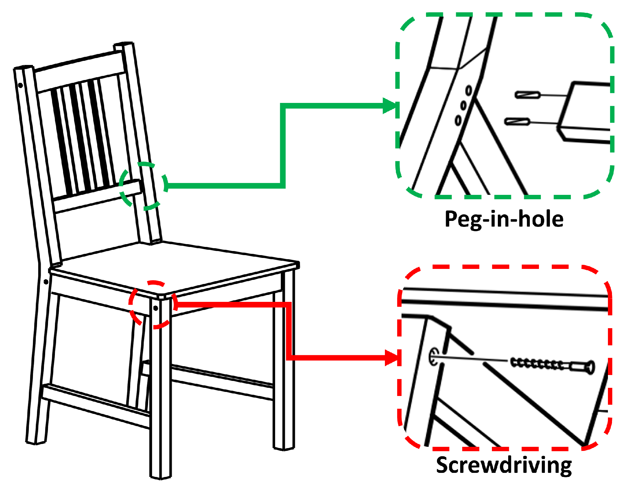
Furniture assembly is a representative example of such tasks, and it includes various elements of general assembly tasks such as pick-and-place, peg-in-hole, and screwdriving tasks. It is considerably inefficient to automate such assembly tasks using multiple specialized robots for each task; thus, research on this topic is in the nascent stages.
Knepper et al. [1] presented a mobile-platform-type multirobot system (IKEAbot) and a new type of gripper for furniture assembly involving the assembly of brittle and small parts, as shown in Figure 1. The proposed gripper uses multiple elastic cables to constrain objects and rotate the restrained objects. IKEAbot can manipulate IKEA table legs and easily assemble the table legs. The screwdriving task is an essential element for an assembly, and therefore, the authors proposed a gripper that can perform a screwing operation to help overcome the limitations of the degree of freedom of the robot arm; however, it was still difficult to perform this task. Suàrez-Ruiz et al. [2] defined manipulation primitives for assembling furniture (Figure 1) using a robot and demonstrated the peg-in-hole task of a wood-pin using two fixed commercial manipulators and grippers. With the same framework presented above, the assembly of an IKEA chair was demonstrated in [3]. In this demonstration, the wooden pins of the IKEA STEFAN chair placed randomly in the work area were assembled successfully; however, screwing was not performed owing to the limitations of commercial manipulators and grippers.
Previous research has suggested new possibilities for assembling robots. Further, these studies indicated that there is an insufficient manipulation of the furniture and the fixing parts. To this end, we implemented the entire assembly process of the IKEA STEFAN chair in the form of cell production using three manipulators [4], and we believe that the proposed screwdriving gripper plays a key role in the demonstration. In this study, we focus on the technology of the screwdriving gripper. The robot system must perform picking and placing, peg-in-hole, and screwdriving tasks to complete the assembly task and assemble the furniture mentioned above. Robotic systems need to have versatile grippers to perform such tasks. Therefore, many grippers have been developed and are continuously being researched. Two-three-finger grippers have been developed and used over a long time; this gripper can perform picking and placing and peg-in-hole tasks [5,6,7,8,9,10]. However, there are many difficulties in performing screwdriving tasks because of the limitation of the degree of freedom.
Several studies have researched an anthropomorphic robotic hand [11,12,13,14,15] that mimics a human hand with high dexterity. The robotic hand has a high degree of freedom and versatility because it uses a joint configuration similar to that of the human hand. In [16], the authors showed that the hex key can be rotated using a high level of in-hand manipulation control using the three-finger gripper. However, it only rotated the hex key that was inserted manually into the hole, and it could not perform the entire process of screwdriving. Soft grippers that use soft materials have been developed recently [17,18,19,20,21,22]. There is no need for a contact force controller because it inherently has compliant characteristics. However, these grippers have limitations in terms of durability and the need for a complex system to control each joint. Therefore, it is difficult to perform screwdriving tasks using soft grippers. A gripper for assembly work requires a reasonable degree of freedom and simple control to perform all three assembly tasks. Existing grippers cannot be used directly for assembly tasks because some grippers lack the degree of freedom required for the task, whereas the others have too many degrees of freedom and require complex controls.
In this study, we present a robotic screwdriving gripper that mimics human two-handed work. The proposed screwdriving gripper classifies the role of each hand by analyzing the two-handed task of humans and performs each role using the finger mechanism of the screwdriving gripper. In the assembly work, the roles of human hands are classified and the functions of each hand are integrated into one three-finger gripper system with 12 degrees of freedom (DoF). The proposed screwdriving gripper comprises grasping and screwdriving parts for gripping objects; assembly tasks such as screwdriving, peg-in-hole, and pick-and-place tasks can be performed with a single screwdriving gripper. The grasping part comprises two fingers and has a different joint configuration from that of the normal gripper. These joint configurations are based on roles such as the pronation and supination of human wrists. The screwdriving part performs tasks such as screwdriving and peg-in hole using a hex key, driver, and insert tip mounted on the end of the finger. The screwdriving finger has a flexible link to comply with the contact without the need for any additional force control or external sensors. A screwdriving and peg-in-hole task strategy using the proposed gripper is presented, and the performance of the gripper is confirmed through experiments. The experimental results indicate that the proposed single screwdriving gripper can perform the tasks required for the assembly, such as screwdriving using a flexible link without needing a force sensor.
The remainder of this paper is organized as follows. Section 2 describes the mechanical structure, concept design, and each function of the robotic screwdriving gripper that simulates the two-handed operation; the electronic part of the gripper is also presented. Section 3 describes task strategies such as screwdriving and peg-in-hole using a screwdriving gripper; further, it presents the operation method of the screwdriving motor for a screwdriving task. The experimental validation and evaluation results are presented in Section 4. Finally, Section 5 presents the conclusions.
2. Design of the Robotic Screwdriving Gripper
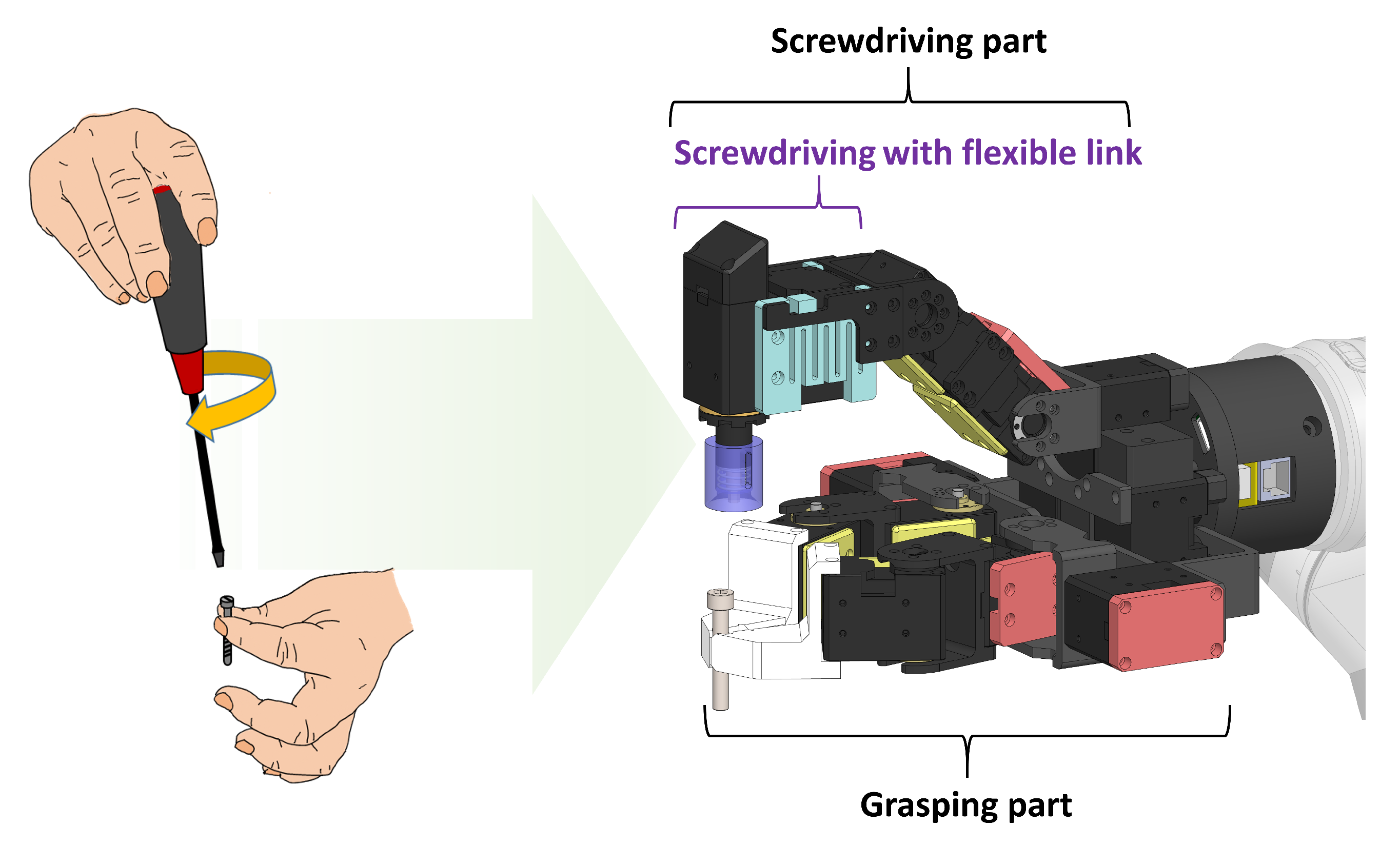
Figure 2 shows that the screwdriving gripper mimics two-handed human work. When humans handle small objects, they manipulate objects in the form of pinch grasps. For large objects or objects requiring large force, humans use a power grasp. Hand manipulation is essential for pinch grasping. In contrast, a power grasp rotates or changes direction using wrist joints or arms because the degree of freedom of the fingers is constrained [23]. When a human performs a screwdriving task, the pinch grips the screw with 2–3 fingers to align it with the driver, hex key, and screw hole. Then, with the other hand, the human uses a power grasp to rotate the screw using a tool such as a hex key.
The proposed screwdriving gripper is designed to perform these functions using one gripper that is divided into a grasping part for grasping objects and a screwdriving part with a hex key and the insert tip attached.
2.1. Grasping Part
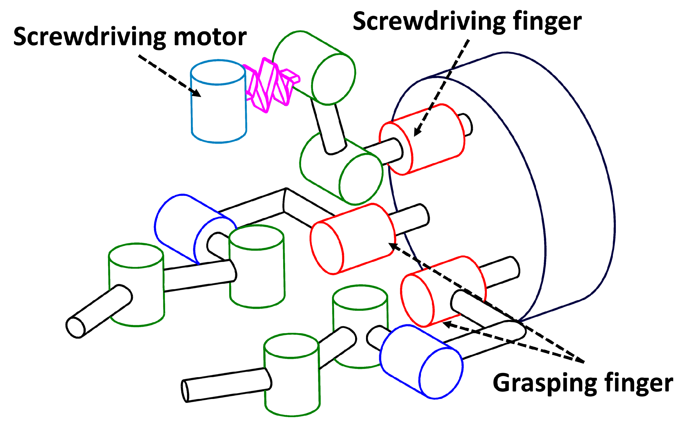
The grasping part grips objects such as screws, wood pins, and other parts. It comprises two fingers and a joint configuration of roll-yaw-pitch-pitch, as shown in Figure 3. The added yaw joint plays the role of the pronation and supination of the human wrist, which allows it to present various paths of the manipulator and perform easy path planning when grasping an object placed on the workbench (Figure 4). Further, the roll joint provides not only pinch grasping used only for grasping fingers but also various configurations to lift or grip objects together with the screwdriving finger. When the object is gripped by grasping the grasping part, the fingertip of the grasping part has a V-shaped groove for the easy handling of small cylindrical objects such as screws. The groove of the fingertip helps align the screw in the vertical direction with the fingertip without additional manipulation, even if the screw is misaligned. Moreover, it can prevent the object from slipping.
2.2. Screwdriving Part
Humans drive a screw using a tool such as a hex key by grasping the hex key and rotating it using their wrist or arm. The hex key is then pressed with an appropriate force so that it can be inserted without being separated from the screw head. The screwdriving part performs this role using one finger, a screwdriving motor, and a flexible link.
The hex key or driver and the screw must be aligned and the screw head must be inserted with a constant force to perform the screwdriving task using a robot. Position control cannot maintain the distance between the screw head and hex key, and it can damage the object or the gripper. The screwdriving gripper is designed to comply with the contact force without a force sensor using the flexible link structure, which is a component of the compliance included in the screwdriving part.
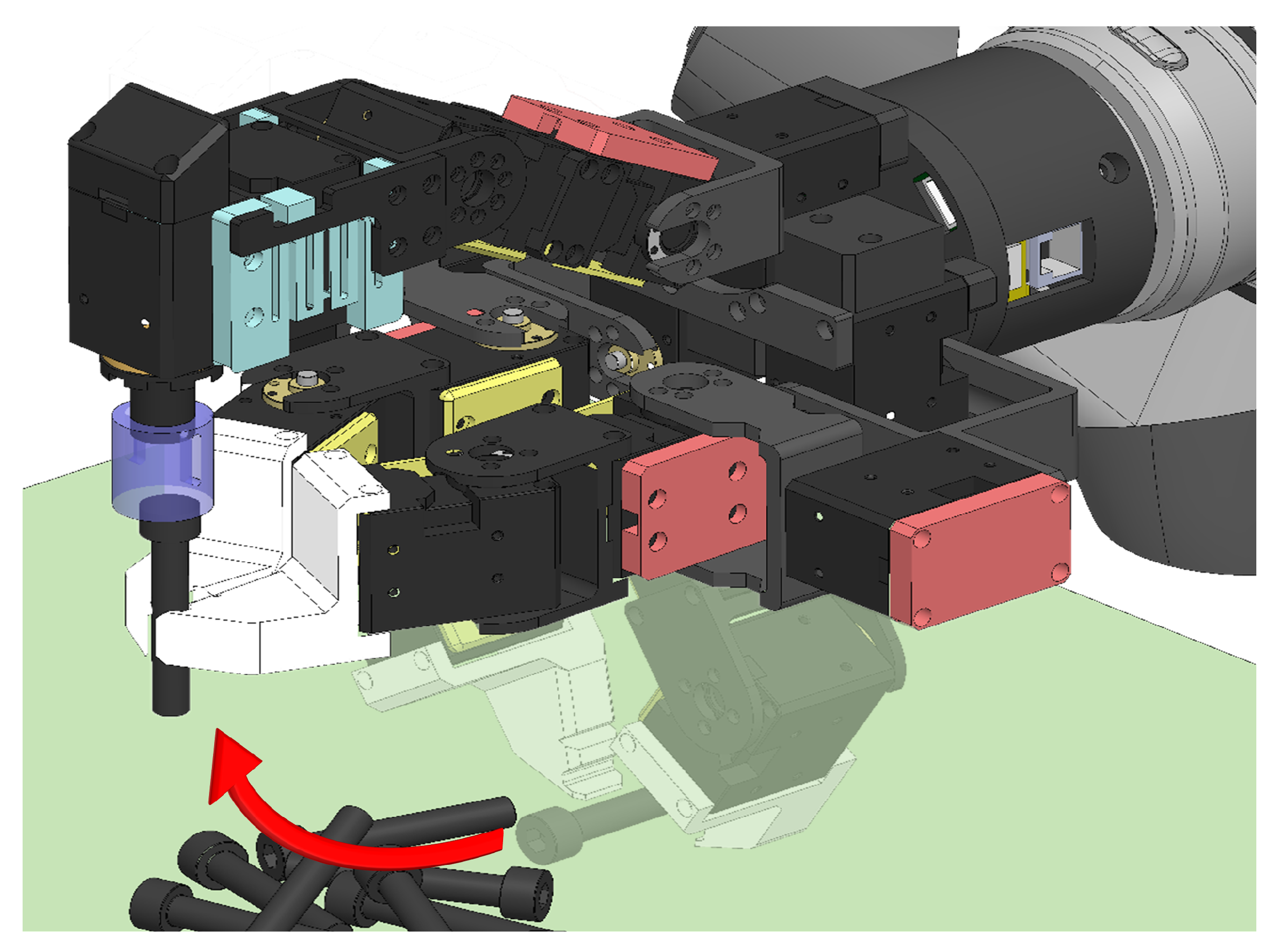
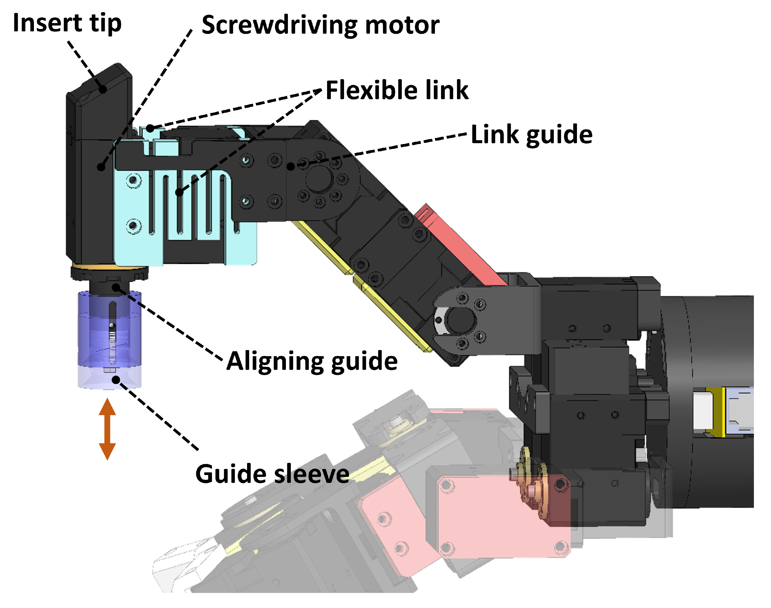
The screwdriving finger is located at the top of the gripper and consists of a roll-pitch-pitch joint configuration of 3-DOF as shown in Figure 3. The link of each joint is composed of a rigid link, whereas the last link connected to the screwdriving motor is composed of a flexible link. The roll joint not only prevents the screw from being stuck by rotating left and right, but it also rotates the screwdriving finger by 180° to enable the use of the insert tip. The screwdriving motor is equipped with a hex key for rotating the screw or an insert tip to insert a driver and a wood pin. The alignment guide attached to the outside of the hex key makes it easy to connect the screw and the drive (Figure 5).
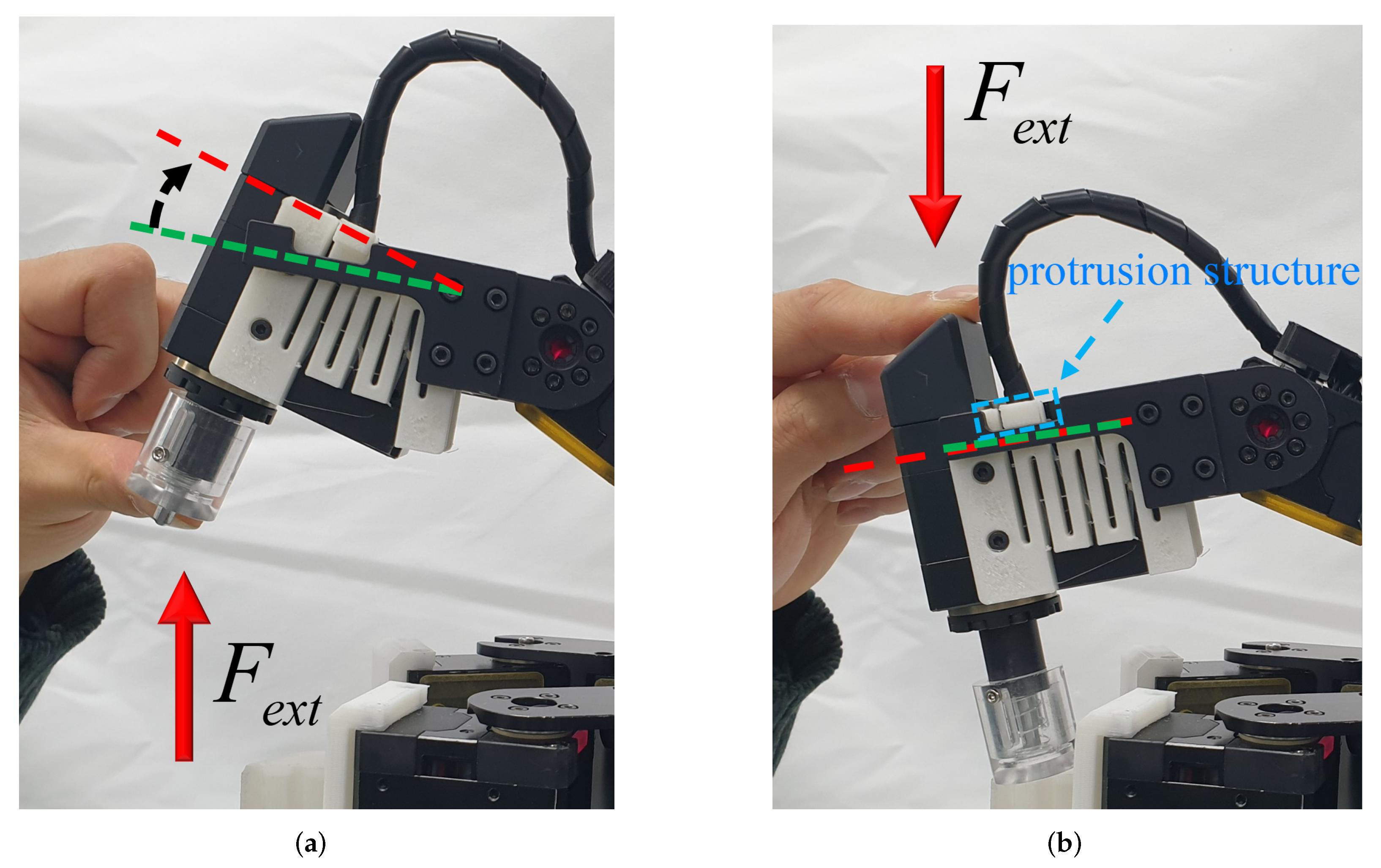
The flexible link is mounted on both sides of the screwdriving finger, together with the link guide. The link guide not only prevents the flexible link from swinging left and right but also makes the bending up and down different. The flexible link is a continuous form of several W shapes, and has a protruding structure in contact with the link guide. This continuous W shape makes it a link compliant element (Figure 6). This flexible link cannot only comply with the contact force without a precise force controller but also prevents the screw and the object from being stuck while driving the screw by providing passive compliance. When a force is applied in the direction opposite to that of gravity, the flexible link bends according to an external force (Figure 6a). When the force is applied in the direction of gravity, the link guide supports the protruded structure of the flexible link which remains horizontal with no bending (Figure 6b). Thus, compliance can be changed according to the direction of the operation. When performing the screwdriving task, the force acts in the direction opposite to that of gravity and the flexible link is bent. However, in the case of a peg-in-hole, in which an insert tip is attached to the top of a screwdriving motor, the force can be stably transmitted to the peg because the insert tip is fixed.
The aligning guide mounted on the screwdriving actuator comprises a guide and a guide sleeve, and they are connected by a spring-slide link. When performing the screwdriving task, the sleeve is inserted into the aligning guide and it protrudes again when the screwdriving task is completed. The inside of the guide sleeve has an oblique shape, which helps align the screw with the alignment guide when the grasping finger inserts the screw into the screwdriving finger without precision position control.
The insert tip is attached to the back of the screwdriving actuator, and it can be pressed on the peg so that the peg is inserted securely when working with the peg-in-hole. The insert tip is designed to be oblique so that the peg and insert tip surfaces are at right angles.
2.3. Specifications of Screwdriving Gripper
The actuator of the robotic screwdriving gripper uses a commercial motor module as the basic component of the gripper; all joints are serially connected. The same joint module is connected serially because the link structure is unnecessary, and therefore, the gripper can be modularized at the joint level. The modular joint structure is easy to maintain, and the joint configuration of the finger can be changed easily. The screwdriving gripper used modular commercial motors and selected an actuator with a high-power density rather than high driving velocity. The motor module used in the gripper link was XM430, and the screwdriving motor was XM540. XM540 weighs twice as much as XM430 but has an approximately 2.5 times higher torque output. The selected motor modules can be supplied with power and controlled with only four wires. Moreover, each motor module and main controller computer communicates using RS485. Furthermore, the motor modules have the advantages of a simple configuration of electronic components as they have built-in sensors.
3. Assembly Task Strategy
In the assembly strategy, position information is acquired using a vision system installed at the top of the workbench. The vision system acquires not only the location information of randomly scattered objects such as screws and wood pins, but also the location information of holes such as screw holes. In addition, the spiral search proposed in [24] is used to insert pegs such as screws into the hole. The spiral search method is proposed to perform the peg-in-hole task without force feedback or passive compliance, and it can overcome the inevitable positional uncertainty of the hole that occurs during the recognition process.
3.1. Screwdriving and Peg-in-Hole
The screwdriving and peg-in-hole task processes were classified into five steps (Figure 7), which are as follows:
- 1.
- Determine the position and size of the screw or wood pin placed on the workbench. The position information of a randomly placed object is obtained using a vision system.
- 2.
- Grip the object. The object is gripped using a gripper [25]. At this time, the object can be grasped with minimal manipulation by the manipulator if the pitch joint of the grasping part mentioned above is used.
- 3.
- Align the gripped object. In the case of screws, the alignment sequence is as follows: screw head—guide sleeve—align guide—screwdriving motor. In the case of a wood pin, the screwdriving finger rotates by 180° to align the surface of the insert tip with the wood pin at right angles.
- 4.
- Align the screw and wood pin to the hole for peg-in-hole operation. Close the gripper holding the object to the hole and manipulate the object with the left and right, up and down, and spiral trajectory to overcome the inevitable positional uncertainty of the hole and allow it to be inserted.
- 5.
- Operate the screwdriving motor to rotate the screw and insert it. The grasping finger is separated from the screw when a certain depth is inserted. When inserting a peg such as a wood pin, the pin is pressed using the insert tip mounted on the screwdriving finger for complete insertion.
3.2. Operation of Screwdriving Motor
Screwdriving is an important assembly operation to connect two objects. The screw must be fully inserted and firmly fixed because it affects durability and stability. In this study, the screwdriving condition is checked using a built-in sensor installed on the motor module without using an external sensor (e.g., a torque sensor).
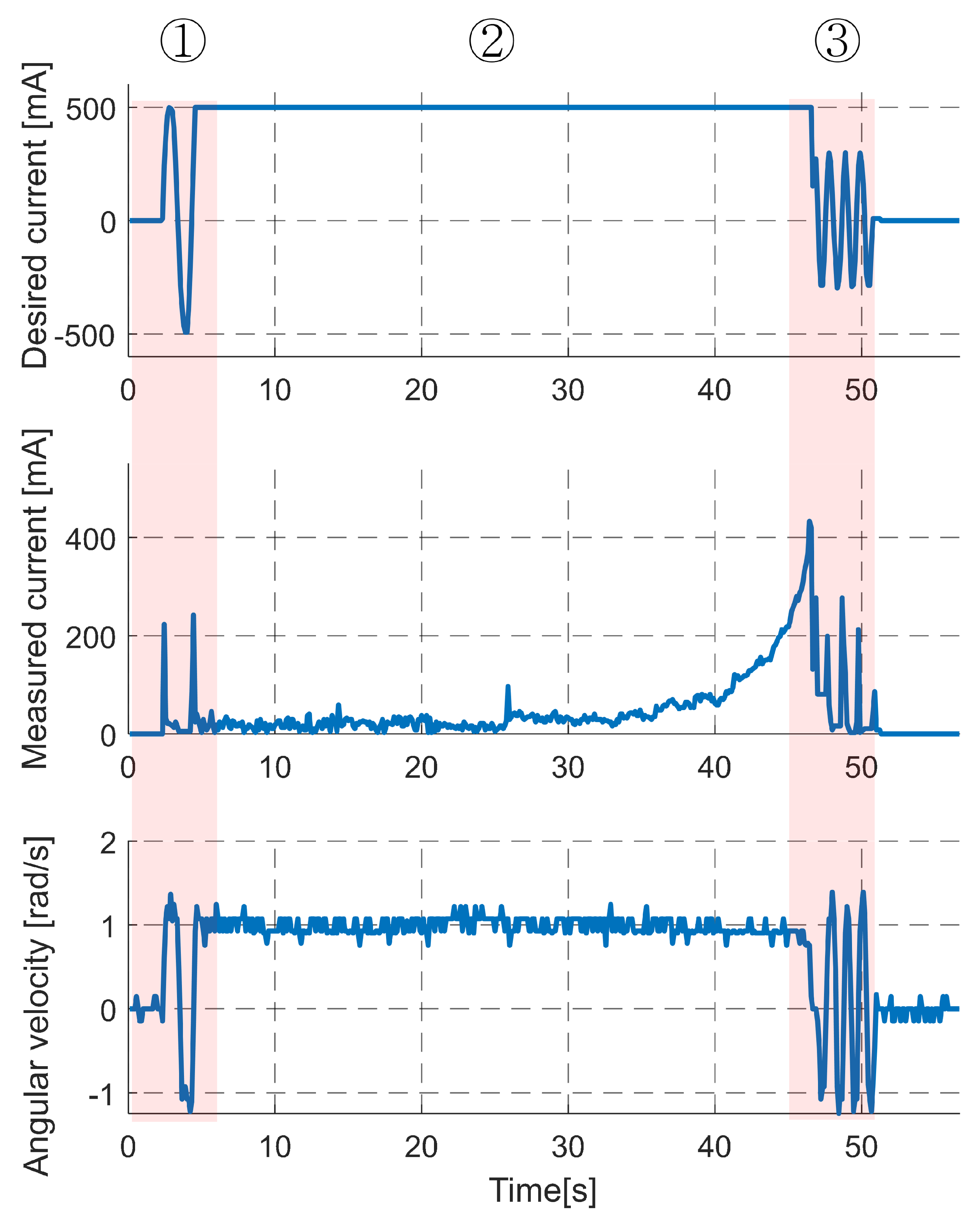
In the screwdriving task, the hex key or driver attached to the screw head and the screwdriving motor must be inserted, and the timing of screw insertion must be determined. In this study, the screwdriving task is classified into three stages based on the operation of the screwdriving motor. The first stage is rotating the screwdriving motor in the clockwise (CW) and counterclockwise (CCW) directions so that the hex key can be inserted into the aligned screw head. The second stage involves inserting the screw by rotating the inserted hex key. During this stage, the velocity of the driving motor is kept constant according to the input value. A dramatic change is detected in the motor velocity which indicates that the insertion of the screw is complete. Finally, in the third stage, the screwdriving motor is rotated in the CW and CCW directions so that the inserted hex key can be easily separated from the screw head.
The strategy is verified experimentally before applying the operating strategy of the proposed screwdriving motor. Figure 8 shows the experimental results of the proposed operation strategy for the screwdriving motor. Here, the first graph represents the desired current; second graph, measured data of the screwdriving motor; and last graph, angular velocity of the hex key. Area ➀ shows the first step of the screwdriving motor operation strategy; the screwdriving motor is rotated CW and CCW to insert the hex key into the screw head. Area ➁ shows the process of inserting the screw while maintaining a constant velocity of the screwdriving motor. The friction force increases as the screw is inserted, and the motor current increases to maintain a constant velocity. Further, the velocity changes dramatically at approximately 46 s in Area ➂. At this time, the screw insertion is determined to be complete, and the screwdriving motor is rotated in the CW and CCW directions to remove the hex key.
The screwdriving motor is driven according to the operation strategy, and it is possible to determine that the screwing is completed using the built-in sensor installed on the motor module.
4. Experiment
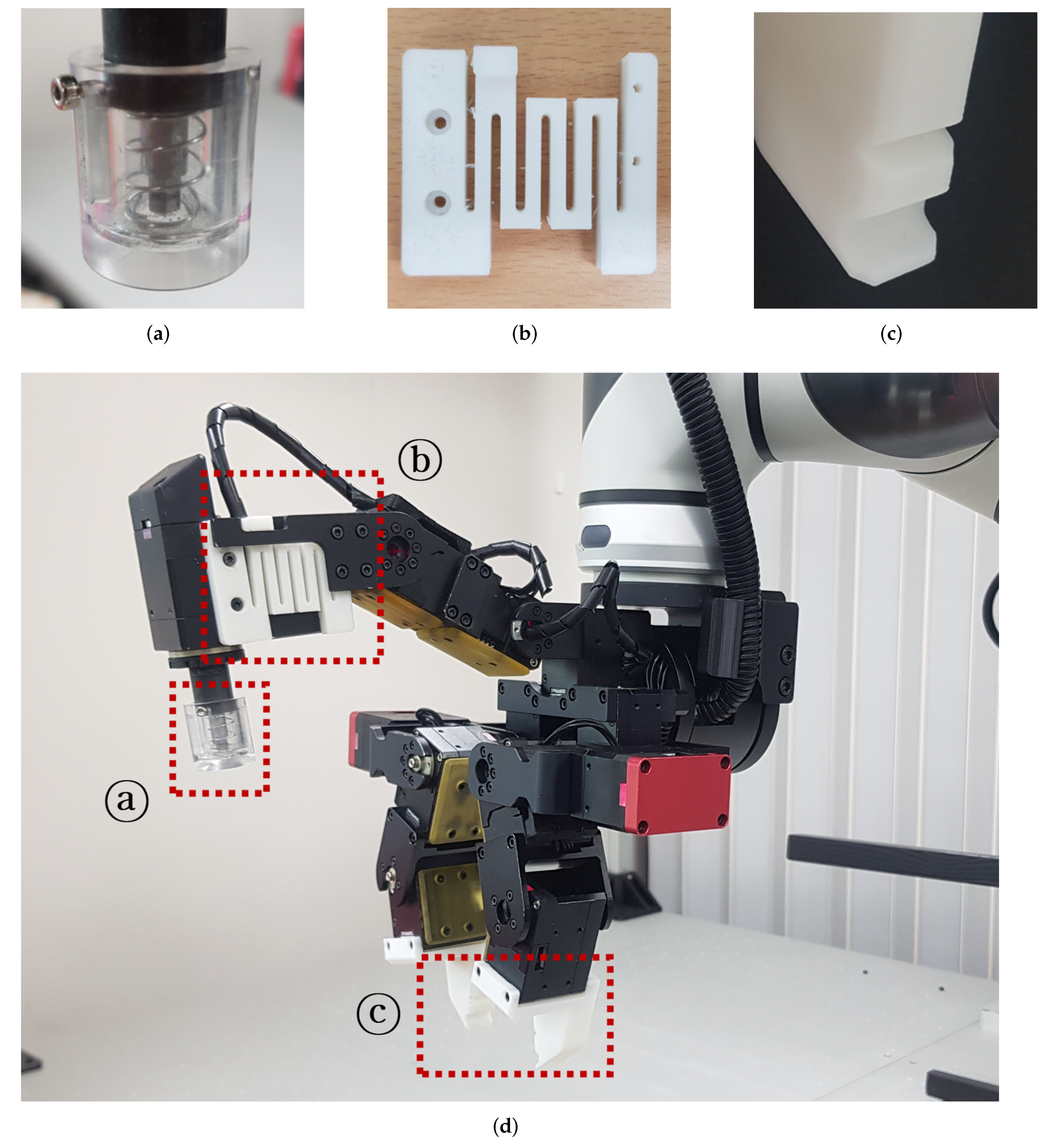
The wood pin peg-in-hole experiment is not covered in this study because it is similar to the screwdriving experiment and is included in the attached video. The screwdriving task includes the pick and place and the peg-in-hole tasks required for the assembly. A prototype of the manufactured screwdriving gripper is shown in Figure 9. Table 1 lists the specification of the manufactured gripper, and the length, width, height of the screwdriving gripper are 25.7 cm, 22.7 cm, and 16.9 cm, respectively. It weighs approximately 1.5 kg and communicates with the main controller of the desktop using RS485.
The sleeve of the align guide is made of transparent acrylic, as shown in Figure 9a, and therefore, the insert process between the screw head and the hex key can be easily checked visually. The flexible link between the screwdriving gripper and fingertip material is ABS (Figure 9b,c), and it is manufactured using a 3D printer. Except for accessories requiring special functions, the flexible link provides the versatility and expandability for the gripper using commercial parts, including motor modules.
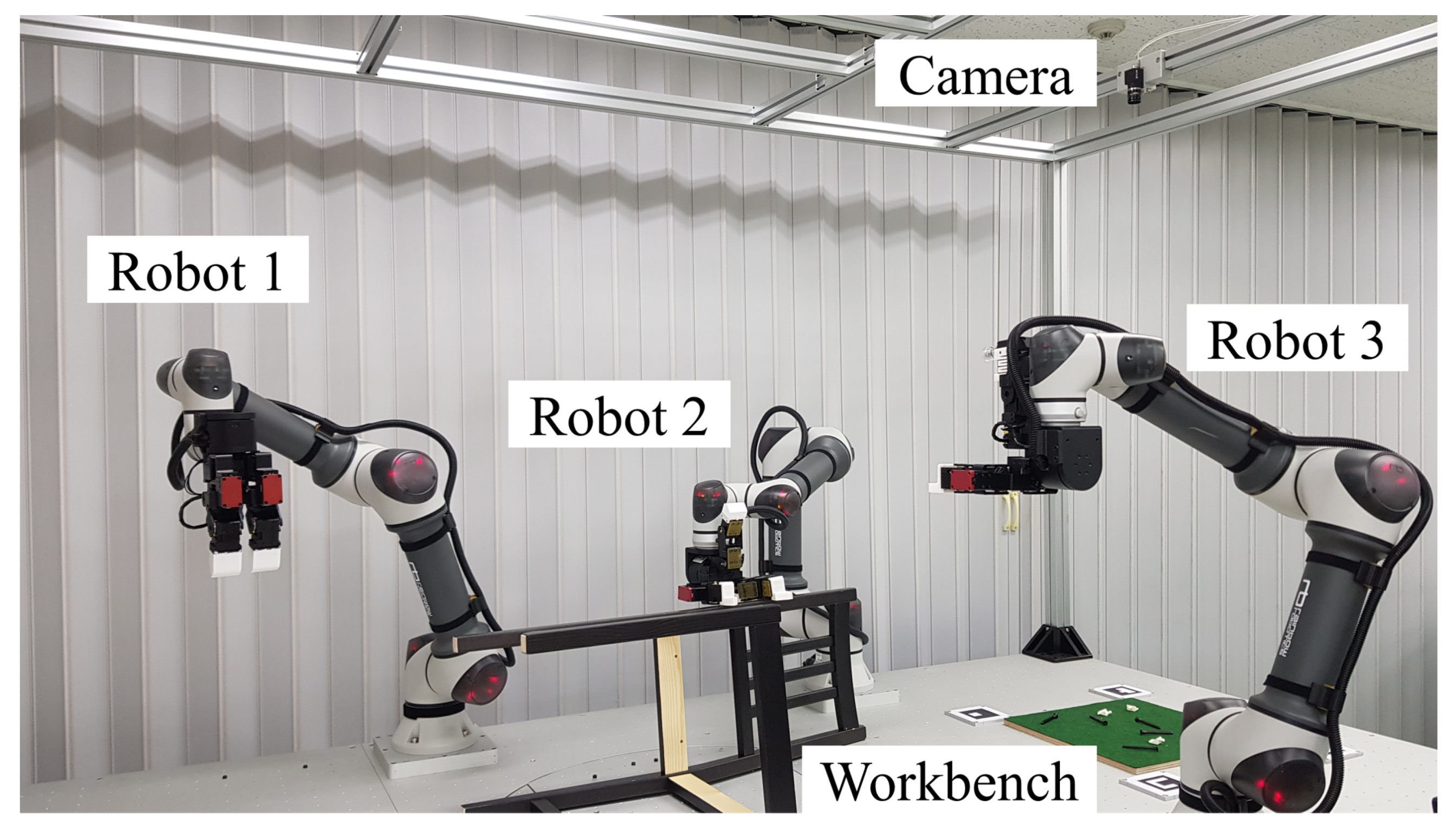
Three robotic manipulators were used in the screwdriving tasks. As shown in Figure 10, the two manipulators (robots 1 and 2) are equipped with multi-fingered grippers instead of screwdriving fingers. These manipulators fix only the wooden frame when performing the screwdriving task. Robot 3 is equipped with a screwdriving gripper to perform screwdriving tasks. A camera is installed at the top of the workbench for recognizing the position of an object, and a green plate is installed to increase the recognition rate of the object.
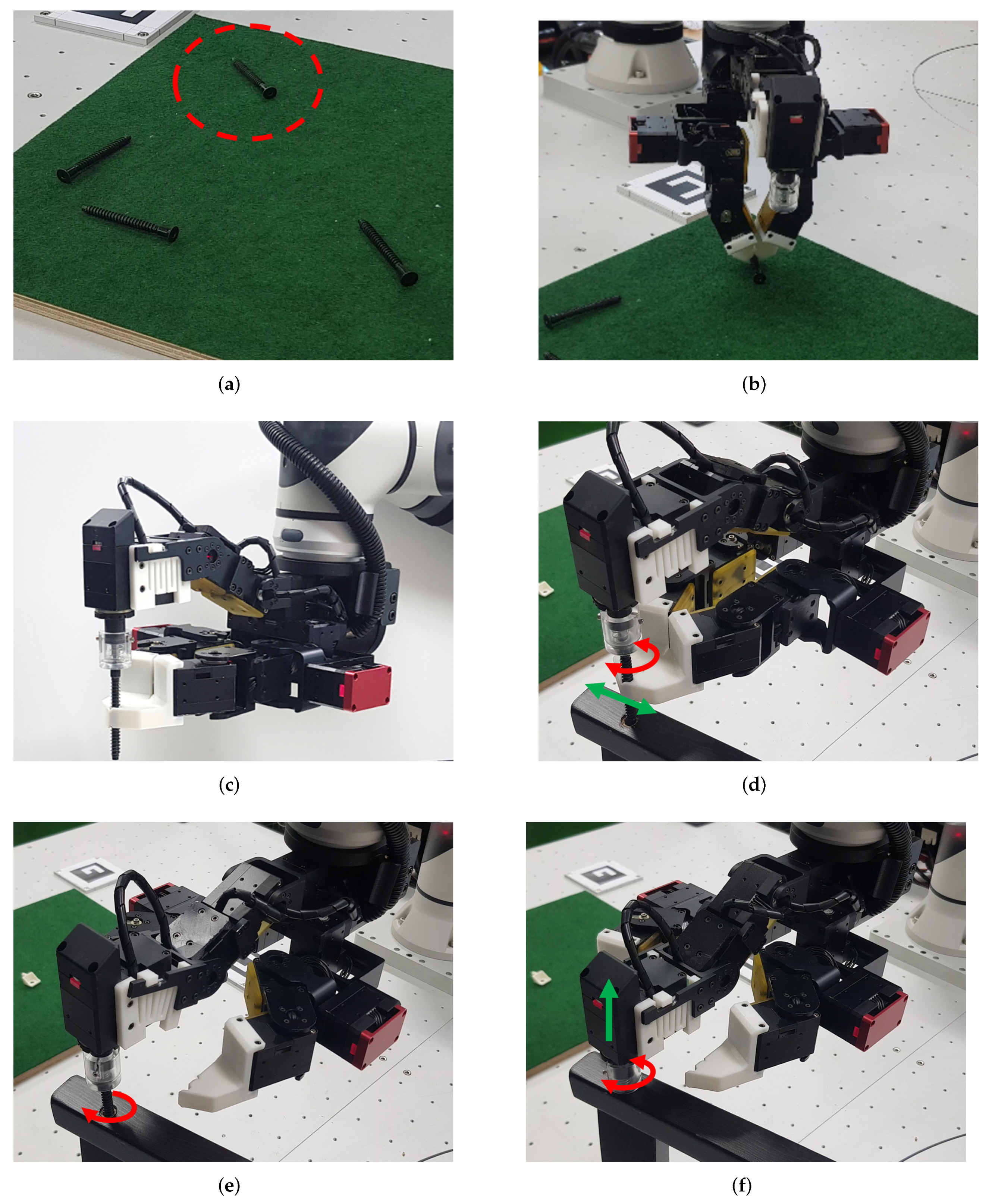
An experiment was performed on the screwdriving task based on the strategy presented in Section 3. Figure 11 shows a snapshot of the test results of the screwdriving task and presents the operation of the robot arm and screwdriving gripper. Figure 11a shows the preparation step for the screwdriving task, and the camera attached to the top of the workbench recognizes the position of the screw on the floor. When the position of the screw is recognized, the screwdriving gripper moves to the position to hold the screw, as indicated in Figure 11b. The screw is held using two fingers of the grasping part and the robot manipulator is raised to align the screw and screwdriving parts.
As shown in Figure 11c, the two grasping fingers hold the screw upward so that the screw head is inserted into the guide sleeve. The screw raises the robot manipulator to prevent contact with the floor and aligns the screw head with the guide sleeve. Then, the location of the screw hole is confirmed by the vision system, and it moves to the position for fastening the screw using the robot manipulator, as indicated in Figure 11d. The robot manipulator moves to the position of the screw hole and maintains its current position until the assembly is completed. In this state, the screwdriving motor rotates in the CW and CCW directions as in the aforementioned operation strategy of the screwdriving motor; the hex key is inserted into the screw head. The screw is then inserted using the spiral search [24] method when using the grasping finger to hold the screw.
When the screw is inserted beyond a certain depth, the grasping finger holding the screw is separated from the screw, as shown in Figure 11e. Figure 11f shows that the flexible link of the screwdriving gripper and the role of the alignment guide ensure that the screw and gripper do not come off, and the screw is inserted into the hole, without changing the position of the robot manipulator. After the screw is inserted, the screwdriving motor is rotated in the CW and CCW directions to prevent the hex key and the screw head from being stuck and to remove the screwdriving finger.
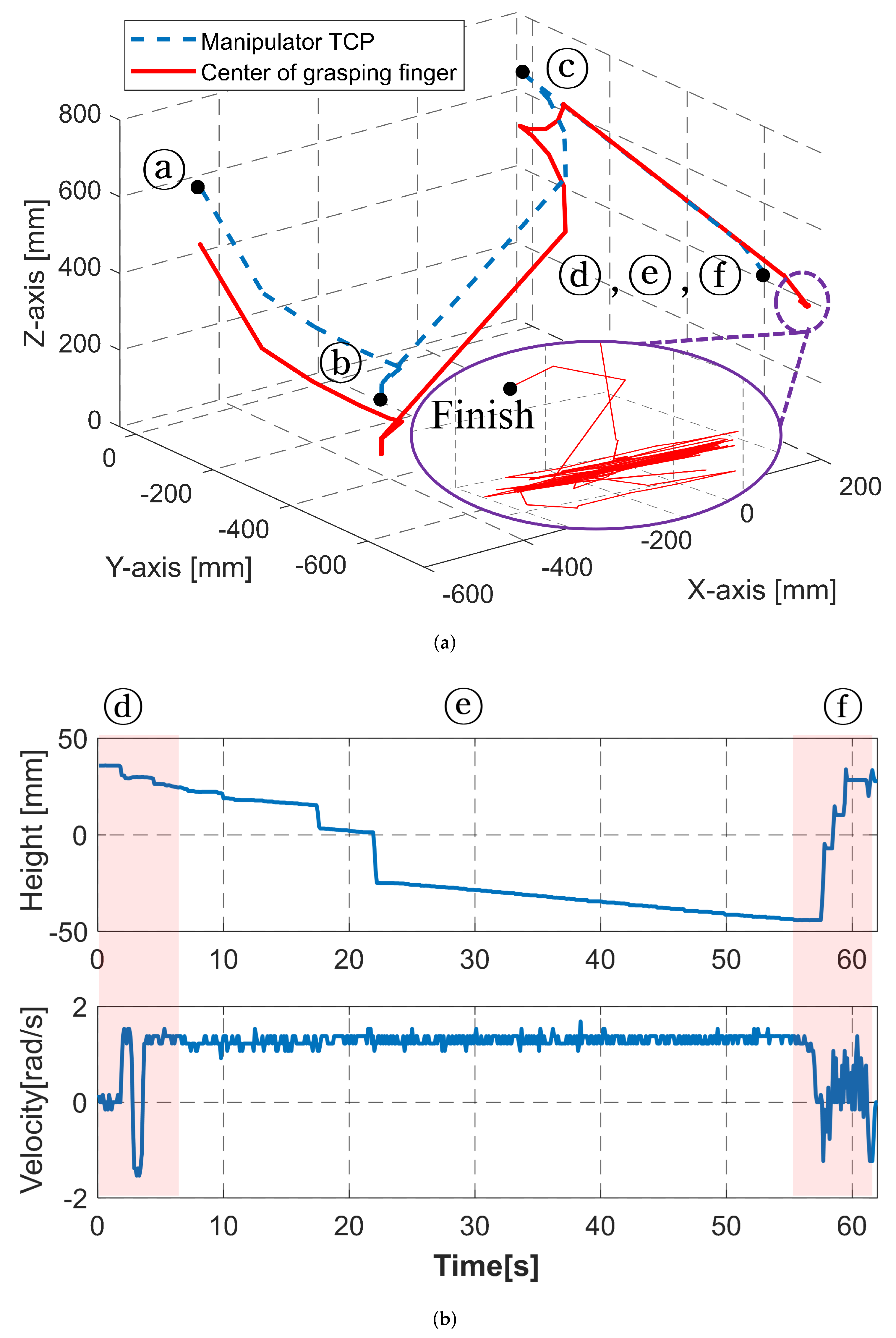
Figure 12 shows the experimental data of the screwdriving task; the order of the circle symbols is the same as the alphabet used in Figure 11. The blue dashed line in Figure 12a represents the position of the robot arm, and the solid red line represents the position of the center point of the grasping finger. Each solid line indicates the path of the robot arm and the grasping finger from the start of the task until the grasping finger inserts the screw into the hole using a spiral search and separates it from the screw. In Figure 12a, ⓐ represents the preparation step, and ⓑ represents, holding the screw. Further, ⓒ indicates aligning the screw and guide sleeve, and ⓓ is the fixed state wherein the robot arm has moved to the screw hole. The enlarged figure with a purple color edge in Figure 12a shows that the grasping finger performs a spiral search.
Figure 12b shows the position of the screwdriving finger and the velocity of the screwdriving motor after the robot arm has moved to the screw hole position until the screwdriving task is completed. Figure 12b shows that the height of the screwdriving finger changes as the screwdriving motor rotates. As shown in ⓕ, the screw is inserted completely and the screwdriving finger is separated from the screw head.
The experimental results of the screwdriving gripper that mimics the two-handed work of a human shows that pick and place, peg-in-hole, and screwdriving tasks that are required for assembly can be performed using a single gripper. The flexible link of the screwdriving finger complies with the contact situation without a force sensor, and the fingertip with a groove can stably grip an object. This experiment showed that assembly is possible based on the screwdriving task strategy and the operation strategy of the screwdriving motor.
5. Conclusions
This study proposed a screwdriving gripper that mimics a human’s two-handed operation for efficient assembly work. Along with pick and place and peg-in-hole, screwdriving is an important task for assembly. The screwdriving gripper was designed to analyze the characteristics of two-handed operation and allow one gripper to perform the functions of each hand. In addition, a joint that mimics the pronation and supination motion of a human wrist joint was used for the gripper finger. This joint helps the robot manipulator to avoid obstacles by making it easy to generate a path when gripping an object. Moreover, a flexible link was adopted to prevent damage to the object or gripper and ensure a safely performed task. This flexible link provided different compliances based on the direction of the external force. Modular commercial actuators were used to provide convenience in repair and manufacturing. This screwdriving gripper that consists of three-fingers and two-parts, showed through experiments that not only screwdriving, but most of the tasks required for assembly can be performed using one gripper.
Future work will focus on improving the screwdriving gripper so that it can be used for a wide range of assembly applications, such as manipulating screws in packages. We plan to analyze the problems of the screwdriving gripper through various assembly experiments such as mechanical elements. Furthermore, we plan to upgrade the hardware and establish motion planning according to the environment. Finally, we plan to use an environment recognition system to classify screws stacked in various sizes and prevent collisions with the surrounding environment.
Author Contributions
Conceptualization, J.-H.B., J.-H.P., J.C.; methodology, S.H., M.-S.C., D.-H.L., J.-H.B.; software, G.-R.J., M.-S.C.; validation, M.-S.C., S.H., Y.-W.S. and D.-H.L.; formal analysis, D.-H.L., J.C. and J.-H.B.; investigation, M.-S.C., S.H. and D.-H.L.; resources, J.-H.B. and J.-H.P.; data curation, M.-S.C. and Y.-W.S.; writing—original draft preparation, S.H., D.-H.L. and J.C.; writing—review and editing, S.H., M.-S.C. and D.-H.L.; visualization, S.H. and D.-H.L.; supervision, J.C., D.-H.L., J.-H.P. and J.-H.B.; project administration, M.-S.C. and J.-H.B.; funding acquisition, J.-H.P. and J.-H.B. All authors have read and agreed to the published version of the manuscript.
Funding
This work was supported by Industrial Strategic Technology Development Program No. 20005024 (Development of intelligent robot technology for object recognition and dexterous manipulation in the real environment) and No. 20014558 (Development of robotic gripper and recognition technology capable of picking multiple kinds of random pieces) funded by the Ministry of Trade, Industry & Energy (MOTIE, Korea).
Institutional Review Board Statement
Not appliable.
Informed Consent Statement
Not appliable.
Data Availability Statement
Not appliable.
Conflicts of Interest
The authors declare no conflict of interest.
References
- Knepper, R.A.; Layton, T.; Romanishin, J.; Rus, D. IkeaBot: An autonomous multi-robot coordinated furniture assembly system. In Proceedings of the 2013 IEEE International Conference on Robotics and Automation, Karlsruhe, Germany, 6–10 May 2013; IEEE: Karlsruhe, Germany, 2013; pp. 855–862. [Google Scholar]
- Suárez-Ruiz, F.; Pham, Q.-C. A framework for fine robotic assembly. In Proceedings of the 2016 IEEE International Conference on Robotics and Automation (ICRA), Stockholm, Sweden, 16–21 May 2016; IEEE: Stockholm, Sweden, 2016; pp. 421–426. [Google Scholar]
- Suárez-Ruiz, F.; Zhou, X.; Pham, Q.-C. Can robots assemble an IKEA chair? Sci. Robot. 2018, 3, eaat6385. [Google Scholar] [CrossRef]
- Bae, J. Robotic Furniture Assembly (Full Version). Available online: https://www.youtube.com/watch?v=hGOejYBf41U (accessed on 21 August 2021).
- Hu, Z.; Wan, W.; Harada, K. Designing a Mechanical Tool for Robots With Two-Finger Parallel Grippers. IEEE Robot. Autom. Lett. 2019, 4, 2981–2988. [Google Scholar] [CrossRef] [Green Version]
- Lee, K.; Wang, Y.; Zheng, C. TWISTER Hand: Underactuated Robotic Gripper Inspired by Origami Twisted Tower. IEEE Trans. Robot. 2020, 36, 488–500. [Google Scholar] [CrossRef]
- Donaire, S.; Borras, J.; Alenya, G.; Torras, C. A Versatile Gripper for Cloth Manipulation. IEEE Robot. Autom. Lett. 2020, 5, 6520–6527. [Google Scholar] [CrossRef]
- Nishimura, T.; Tennomi, M.; Suzuki, Y.; Tsuji, T.; Watanabe, T. Lightweight, High-Force Gripper Inspired by Chuck Clamping Devices. IEEE Robot. Autom. Lett. 2018, 3, 1354–1361. [Google Scholar] [CrossRef]
- Kim, Y.-J.; Song, H.; Maeng, C.-Y. BLT Gripper: An Adaptive Gripper With Active Transition Capability Between Precise Pinch and Compliant Grasp. IEEE Robot. Autom. Lett. 2020, 5, 5518–5525. [Google Scholar] [CrossRef]
- Backus, S.B.; Dollar, A.M. An Adaptive Three-Fingered Prismatic Gripper With Passive Rotational Joints. IEEE Robot. Autom. Lett. 2016, 1, 668–675. [Google Scholar] [CrossRef]
- Min, S.; Yi, S. Development of Cable-driven Anthropomorphic Robot Hand. IEEE Robot. Autom. Lett. 2021, 6, 1176–1183. [Google Scholar] [CrossRef]
- Zhang, Z.; Han, T.; Pan, J.; Wang, Z. Design of Anthropomorphic Fingers With Biomimetic Actuation Mechanism. IEEE Robot. Autom. Lett. 2019, 4, 3465–3472. [Google Scholar] [CrossRef]
- Lee, D.-H.; Park, J.-H.; Park, S.-W.; Baeg, M.-H.; Bae, J.-H. KITECH-Hand: A Highly Dexterous and Modularized Robotic Hand. IEEE/ASME Trans. Mechatronics 2017, 22, 876–887. [Google Scholar] [CrossRef]
- Yang, H.; Wei, G.; Ren, L.; Qian, Z.; Wang, K.; Xiu, H.; Liang, W. A low-cost linkage-spring-tendon-integrated compliant anthropomorphic robotic hand: MCR-Hand III. Mech. Mach. Theory 2021, 158, 104210. [Google Scholar] [CrossRef]
- Santina, C.D.; Piazza, C.; Grioli, G.; Catalano, M.G.; Bicchi, A. Toward Dexterous Manipulation With Augmented Adaptive Synergies: The Pisa/IIT SoftHand 2. IEEE Trans. Robot. 2018, 34, 1141–1156. [Google Scholar] [CrossRef]
- Kim, Y.-J.; Lee, Y.; Kim, J.; Lee, J.W.; Park, K.M.; Roh, K.S.; Choi, J.Y. RoboRay hand: A highly backdrivable robotic hand with sensorless contact force measurements. In Proceedings of the 2014 IEEE International Conference on Robotics and Automation (ICRA), Hong Kong, China, 31 May–7 June 2014; IEEE: Hong Kong, China, 2014; pp. 6712–6718. [Google Scholar]
- Achilli, G.M.; Valigi, M.C.; Salvietti, G.; Malvezzi, M. Design of Soft Grippers with Modular Actuated Embedded Constraints. Robotics 2020, 9, 105. [Google Scholar] [CrossRef]
- Zhou, J.; Chen, S.; Wang, Z. A Soft-Robotic Gripper With Enhanced Object Adaptation and Grasping Reliability. IEEE Robot. Autom. Lett. 2017, 2, 2287–2293. [Google Scholar] [CrossRef]
- Liu, S.; Wang, F.; Liu, Z.; Zhang, W.; Tian, Y.; Zhang, D. A Two-Finger Soft-Robotic Gripper with Enveloping and Pinching Grasping Modes. IEEE/ASME Trans. Mechatronics 2020, 26, 146–155. [Google Scholar] [CrossRef]
- Alizadehyazdi, V.; Bonthron, M.; Spenko, M. An Electrostatic/Gecko-Inspired Adhesives Soft Robotic Gripper. IEEE Robot. Autom. Lett. 2020, 5, 4679–4686. [Google Scholar] [CrossRef]
- Li, Y.; Chen, Y.; Ren, T.; Hu, Y.; Liu, H.; Lin, S.; Yang, Y.; Li, Y.; Zhou, J. A Dual-Mode Actuator for Soft Robotic Hand. IEEE Robot. Autom. Lett. 2021, 6, 1144–1151. [Google Scholar] [CrossRef]
- Zhou, J.; Yi, J.; Chen, X.; Liu, Z.; Wang, Z. BCL-13: A 13-DOF Soft Robotic Hand for Dexterous Grasping and In-Hand Manipulation. IEEE Robot. Autom. Lett. 2018, 3, 3379–3386. [Google Scholar] [CrossRef]
- Cutkosky, M.R. On grasp choice, grasp models, and the design of hands for manufacturing tasks. IEEE Trans. Robot. Autom. 1989, 5, 269–279. [Google Scholar] [CrossRef]
- Park, H.; Park, J.; Lee, D.-H.; Park, J.-H.; Baeg, M.-H.; Bae, J.-H. Compliance-Based Robotic Peg-in-Hole Assembly Strategy Without Force Feedback. IEEE Trans. Ind. Electron. 2017, 64, 6299–6309. [Google Scholar] [CrossRef]
- Bae, J.H.; Park, S.W.; Kim, D.; Baeg, M.H.; Oh, S.R. A grasp strategy with the geometric centroid of a groped object shape derived from contact spots. In Proceedings of the 2012 IEEE International Conference on Robotics and Automation (ICRA), St Paul, MN, USA, 14–19 May 2012; IEEE: Saint Paul, MN, USA, 2012; pp. 3798–3804. [Google Scholar]
Figure 1.
Example of assembly that requires screwdriving and peg-in-hole tasks as well as pick and place.
Figure 1.
Example of assembly that requires screwdriving and peg-in-hole tasks as well as pick and place.

Figure 2.
Screwdriving task performed by a human and a gripper that mimics a human two-handed operation.
Figure 2.
Screwdriving task performed by a human and a gripper that mimics a human two-handed operation.

Figure 3.
Kinematic structure of the screwdriving gripper. The red, blue, and green cylinders represent roll, yaw, and pitch, respectively. The light blue cylinder is a screwdriving motor.
Figure 3.
Kinematic structure of the screwdriving gripper. The red, blue, and green cylinders represent roll, yaw, and pitch, respectively. The light blue cylinder is a screwdriving motor.

Figure 4.
Path planning of grasping parts for screwdriving and alignment of screws and aligning guides.
Figure 4.
Path planning of grasping parts for screwdriving and alignment of screws and aligning guides.

Figure 5.
Screwdriving part of the gripper including the screwdriving motor and flexible link.

Figure 6.
Flexible link shape according to external force: (a) flexible link deformed by force in a direction opposite to that of gravity (b) flexible link supported on link guide.
Figure 6.
Flexible link shape according to external force: (a) flexible link deformed by force in a direction opposite to that of gravity (b) flexible link supported on link guide.

Figure 7.
Procedure of screwdriving and peg-in-hole tasks using the screwdriving gripper.

Figure 8.
Results of the screwdriving motor operation strategy experiment: desired current, measured current, and angular velocity.
Figure 8.
Results of the screwdriving motor operation strategy experiment: desired current, measured current, and angular velocity.

Figure 9.
Manufactured screwdriving gripper and parts: (a) Align guide and guide sleeve. (b) Flexible link (c) Fingertip, and (d) Robotic screwdriving gripper.
Figure 9.
Manufactured screwdriving gripper and parts: (a) Align guide and guide sleeve. (b) Flexible link (c) Fingertip, and (d) Robotic screwdriving gripper.

Figure 10.
Experimental environment of the screw driving task with a cooperative robot arm.

Figure 11.
Snapshots of the screwdriving task. (a) Initial state and detecting object (b) Object grip (c) Aligning (d) Finding hole and aligning (e) Screwdriving. (f) Complete process.
Figure 11.
Snapshots of the screwdriving task. (a) Initial state and detecting object (b) Object grip (c) Aligning (d) Finding hole and aligning (e) Screwdriving. (f) Complete process.

Figure 12.
Result of screwdriving task. (a) Center of grasping finger and a manipulator path. (b) Position of the screwdriving finger and velocity of screwdriving motor.
Figure 12.
Result of screwdriving task. (a) Center of grasping finger and a manipulator path. (b) Position of the screwdriving finger and velocity of screwdriving motor.


Table 1.
Specifications of the screwdriving gripper.
| Quantity | Value |
|---|---|
| Number of Fingers | 3-Finger |
| Degree of Freedom | 12-DoF |
| Dimension [cm] | L: 25.7, W: 22.7, H: 16.9 |
| Weight [kg] | 1.5 |
| Actuator | Link: XM430 Screwdriving: XM540 |
| Communication | RS485 |
Publisher’s Note: MDPI stays neutral with regard to jurisdictional claims in published maps and institutional affiliations. |
© 2022 by the authors. Licensee MDPI, Basel, Switzerland. This article is an open access article distributed under the terms and conditions of the Creative Commons Attribution (CC BY) license (https://creativecommons.org/licenses/by/4.0/).
Share and Cite
MDPI and ACS Style
Han, S.; Choi, M.-S.; Shin, Y.-W.; Jang, G.-R.; Lee, D.-H.; Cho, J.; Park, J.-H.; Bae, J.-H. Screwdriving Gripper That Mimics Human Two-Handed Assembly Tasks. Robotics 2022, 11, 18. https://doi.org/10.3390/robotics11010018
AMA Style
Han S, Choi M-S, Shin Y-W, Jang G-R, Lee D-H, Cho J, Park J-H, Bae J-H. Screwdriving Gripper That Mimics Human Two-Handed Assembly Tasks. Robotics. 2022; 11(1):18. https://doi.org/10.3390/robotics11010018
Chicago/Turabian StyleHan, Sangchul, Myoung-Su Choi, Yong-Woo Shin, Ga-Ram Jang, Dong-Hyuk Lee, Jungsan Cho, Jae-Han Park, and Ji-Hun Bae. 2022. "Screwdriving Gripper That Mimics Human Two-Handed Assembly Tasks" Robotics 11, no. 1: 18. https://doi.org/10.3390/robotics11010018
Note that from the first issue of 2016, this journal uses article numbers instead of page numbers. See further details here.