
Herbicide Ballistic Technology for Unmanned Aircraft Systems


1
Department of Molecular Biosciences and Bioengineering, University of Hawai‘i at Mānoa, Honolulu, HI 96822, USA
2
Department of Agronomy, Center for Aquatic and Invasive Plants, University of Florida, Gainesville, FL 32611, USA
*
Author to whom correspondence should be addressed.
Robotics 2022, 11(1), 22; https://doi.org/10.3390/robotics11010022
Submission received: 21 December 2021
/
Revised: 28 January 2022
/
Accepted: 1 February 2022
/
Published: 3 February 2022
(This article belongs to the Section Agricultural and Field Robotics)
Abstract
:Miconia is a highly invasive plant species with incipient plants occupying remote areas of Hawaiian watersheds. Management of these incipient plants is integral to current containment strategies. Herbicide Ballistic Technology (HBT) has been used for 8 years from helicopters as a precision approach to target individual plants. We have developed a prototype HBT applicator integrated onto an unmanned aircraft system, HBT-UAS, which offers the same precision approach with a semi-automated flight plan. Inclusion of the HBT payload resulted in statistically significant deviations from programmed flight plans compared to the unencumbered UAS, but the effect size was lower than that observed for different stages of flight. The additional payload of the HBT-UAS resulted in a large reduction in available flight time resulting a limited range of 22 m. The projectile spread of the HBT-UAS, within a 2–10 m range, had a maximum CEP of 1.87–5.58 cm. The most substantial limitation of the current prototype HBT-UAS is the available flight time. The use of larger capacity UAS and potential for beyond visual line of sight operations would result in a substantial improvement in the serviceable area and utility of the HBT-UAS for containment of invasive plants.
1. Introduction
Hawaii is a major hotspot for invasive species [1]. Effects of these invasions include increases in wildfire frequency and size [2], disruptions in nutrient cycling [3], and increased water use [4]. Miconia calvescens DC (miconia) is a melastome native to rain forests in central and south America and was introduced to Hawaii in 1961 [5,6]. Miconia may reach a height of 10 to 15 m and forms dense monotypic stands in invaded areas [6]. Miconia stochastically colonizes remote forested watershed via zoochory, where a single, isolated plant can threaten relatively large areas with autogamous fruiting [7]. Herbicide treatments from a helicopter platform are reliable and lethal to individual miconia plants. Thus, strategic containment of the invasion is largely driven by detection, where you can only treat what can be found. Leary et al. [8] described manned helicopter search operations constituting 75% of the operational cost and a majority of that effort necessarily searching areas where miconia was not found.
Unmanned Aerial Systems (UAS) provide a platform for remote sensing and have been used for mapping the distributions of plants (e.g., invasive and endangered) and pests for forest management [8,9,10,11,12,13,14,15,16,17,18]. Advancements have been made in automated detection of miconia from georeferenced UAS imagery which can replace and/or expand search operations at reduced costs [13,15,19].
Due to the large amount of tour helicopter and other general aviation activities in Hawaii, the FAA has imposed noise abatement and voluntary avoidance areas, largely in and around residential areas [20]. Voluntary avoidance areas are areas where pilots are requested to avoid overflight at low altitudes due to noise-sensitivity or other circumstances. Approximately 10% of the detected miconia on the island of Maui are contained in these areas (Figure 1).
For comprehensive strategic management of miconia on Maui, we are developing complementary UAS detection and treatment systems better suited for areas near the urban/wildlife interface. With the lifting of regulatory barriers, UAS have gradually seen a greater use in pest management [21,22,23]. The use of UAS for aerial application of pesticides originated in agricultural cropping systems [24,25,26,27,28,29,30,31,32,33,34]. Almost all of the commercial applicator systems are designed for automated broadcast applications to rapidly cover large swaths in open, homogenous field settings. These systems are less compatible with more discriminant, individual plant treatments in complex forest landscapes, such as the natural areas of Hawaii [35,36,37].
Herbicide Ballistic Technology (HBT) is a novel pesticide application technology consisting of encapsulated herbicide formulations in soft-gel projectiles that are dispensed with a low-pressure, electro-pneumatic marker [38,39]. It was developed as a precision application tool intended for treating individual plant targets with long-range accuracy (i.e., up to 30 m) and often from oblique angles allowing for effective treatments on targets occupying steep, inaccessible terrain [39]. The HBT-G4U200 With Garlon® 4 Ultra projectile is registered as an FIFRA 24(c) Special Local Need pesticide in Hawaii for miconia and strawberry guava [40]. The 0.68 caliber (17.3 mm) projectile contains a sublethal dose of triclopyr (10.07% ai; 89.93% inert ingredients) and requires a minimum of five projectiles per branching point on a miconia leaf canopy to be lethal. Current adoptions of HBT have been developed for manned helicopter operations, which greatly enhanced surveillance strategies targeting highly remote, incipient populations. Since 2012, hundreds of helicopter missions have eliminated over 26,000 incipient miconia targets protecting over 17,000 ha of the East Maui Watershed.
Here, we seek to expand the target range capabilities of HBT with the development of a UAS-mounted HBT applicator (HBT-UAS) that can be remotely operated by a ground crew to engage targets within visible line of sight. This novel miconia management platform would have an operational fit in wildland areas interfacing rural-residential communities and terrain that is further prohibitive to ground management. The developed prototype consists of an electro-pneumatic system to discharge projectiles and 2-axis gimbal operated by a remote control. The current HBT-UAS platform is designed for a two-member crew operating the aircraft within visual line of sight and the payload operator making use of a first-person-view (FPV) camera feed for precision treatment. This study consists of two primary objectives: (i) to determine the viability of flying with an HBT payload and (ii) examine the accuracy and precision of the HBT treatment. We hypothesize that the gimbal-marker system will increase the power required to operate the aircraft due to the weight which will limit the available flight time but will not otherwise adversely affect flight stability, and that the system can deliver the pesticide dose with sufficient precision and accuracy to treat a miconia target from a minimum safe distance and oblique angle.
2. Design
2.1. Concept of Operations
The HBT-UAS operates in a similar fashion to manned helicopter operations where the pilot is responsible for operation of the aircraft and the payload operator is responsible for treatment. There are four phases of operation (Figure 2): (1) launch, (2) target acquisition, (3) treatment, and (4) return to launch site.
In the target acquisition phase, the pilot moves the UAS into position for the payload operator to be able to perform the treatment. In manned HBT operations, the pilot and other crew are conducting surveillance operations and will treat miconia on detection. Available UAS flight time and line of sight restrictions substantially limit the ability of this type of operation for the proposed HBT-UAS system. Consequently, it is envisioned that HBT-UAS will operate from an accessible home point to treat known targets identified from previous ground or aerial (e.g., UAS) surveillance missions [15]. Approximate target coordinates from these surveys can be used to automate the initial approach to the target. From there, the pilot would assume manual control to maneuver the UAS into the most effective position for target treatment, in consultation with the payload operator.
The payload operator views a live video feed (600 × 480 px) colinear with the HBT marker barrel (Figure 3), and correspondingly controls an electronic gimbal to align it to the target and a servo to trigger the treatment application. The payload operator communicates with the pilot to coordinate the aircraft position and attitude and for clearance to apply the treatment. Once the treatment is finished, the pilot may either continue on to maneuver the aircraft to position to treat nearby targets or return to the launch site. This depends on the available battery charge and/or projectile inventory to complete the next treatment and still return home.
2.2. Component Selection
The HBT-UAS prototype was designed to mount on an S1000+ octocopter (SZ DJI, Shenzhen, China) with an A3 flight controller (SZ DJI), and retractable landing gear (Figure 4). The maximum takeoff weight of the S1000+ is 11 kg, with a hover time of 15 min when equipped with a 6S 15,000 mAh battery at 9.5 kg takeoff weight. The customized gimbal-marker system was designed and fabricated in collaboration with Tippmann (Fort Wayne, IN, USA). The system is mounted under the fuselage between the landing gear by four hardpoints. Two linear actuators (L16-50-150-6-R Actuonix, Victoria, BC, Canada) control the attitude of the marker and a third (HS-5645MG, Hitec RCD, Cheongwon-gun, Korea) engages the pneumatic valve to discharge projectiles. An FPV camera (Fat Shark 700 CMOS 700 TVL, Stockholm, Sweden) is mounted in the front of the HBT marker with a clear view of the barrel, and electronics are housed in the rear of the HBT payload assembly. The aircraft is controlled by DJI Lightbridge 2 remote ground station which uses a 100 mW 2.4 GHz transmitter. The gimbal marker system is controlled by a Spektrum DX8 G2 (Horizon Hobby, Champaign, IL, USA) remote ground station with an AR8000 transmitter and receiver which uses a 100 mW 2.4 GHz transmitter. Video from the FPV camera is transmitted by a 250 mW 5.8 GHz video transmitter (Fat Shark A/V transmitter) viewed by the payload operator through FPV goggles (Fat Shark Dominator v3).
The total weight of the gimbal-marker system is approximately 4.0 kg and the total takeoff weight of the aircraft with battery (6S 15,000 mAh MaxAmps, Spokane, WA, USA) and gimbal-marker system and a full hopper with 180 projectiles is 10.9 kg. The compressed air cylinder (Tippmann 26/3000, Tippmann, Fort Wayne, IN, USA) when charged to 5.86 MPa contains enough air to discharge up to 500 projectiles under the regulator settings and other conditions summarized in Table 1. The center of gravity of the UAS with the gimbal-marker system loaded is 13.9 cm behind the leading edge of the center frame, which we compensated for by positioning the aircraft battery 2.4 cm forward of its normal position.
2.3. Projectile Mechanics
To estimate the muzzle velocity and deviation of the projectile trajectory from the axis of the barrel, we considered forces on the projectile both before and after exiting the barrel. Within the barrel motion of the HBT projectile is governed by the sum of the force exerted by the compressed gas entering the barrel, atmospheric pressure, and friction between the barrel and projectile surface.
where F is the sum of forces acting on the projectile, m is the mass of the projectile, x is the position of the projectile, t is time, AB is the cross-sectional area of the barrel, PB(t) is the pressure of the compressed gas in the barrel, and f is the force due to friction (Figure 5). All pressures are relative to atmospheric pressure.
The pressure of the gas in the barrel is dependent on the flow of compressed gas from the tank into the barrel which can be described by the ideal gas law:
where PR is the regulated pressure through the solenoid, V0 is the volume of the tank, VB(t) is the volume of gas in the barrel behind the projectile, NB(t) is the number of molecules of compressed gas in the barrel, kB is Boltzmannn’s constant (1.38 × 10⁻²³ J·K−1), and T is the absolute temperature of the compressed gas.
The volume of gas in the barrel behind the projectile, VB, is defined as
where Vd is the initial volume of space in the barrel behind the resting projectile. The molecular flow rate (Q) from the tank, through the regulator and solenoid, to the barrel follows a choked regime controlled by the regulator (set to pressure PR) on the connector between the tank and the solenoid valve [41] (assuming ideal gas behavior):
where B is an engineering constant to convert into molecules per unit time (3.11 × 10¹⁹ K1/2(Pa·s)−1, Cv is the flow coefficient of the valve, r is the ratio of airflow through the valve, Gg is the specific gravity of the gas mixture (a value of 1 by definition when using compressed air). The ratio of airflow through the valve, r, is given by Rohrbach et al. [41]:
The flow from the tank and into the barrel can then be described as:
Once the projectile leaves the barrel its motion is governed by gravity, lift and drag forces (Figure 6). This motion can be described by Robinson and Robinson [42]
where is the position vector of the projectile relative to the end of the barrel, is the velocity vector, is the density of air, A is the cross-sectional area of the projectile, CD is the drag coefficient, CL is the lift coefficient, is the velocity vector of prevailing winds, is the angular velocity vector, ω is the magnitude of the angular velocity, and is the force due to gravity. An initial value of angular velocity of the projectile at the exit of the barrel was estimated based on the assumption that maximum angular velocity would be generated if the projectile is frictionless on all barrel surfaces except for the line at the bottom of the barrel where no slipping occurs such that linear motion corresponds to the rate of the projectile rolling on this line. The resulting magnitude of the angular velocity is
where tB is the time for the projectile to travel the length of the barrel based on the dynamics of the pneumatics described above.
A simulation of the velocity of the projectile within the barrel (Figure 7A) was constructed based on Equations (1)–(6) and the parameters in Table 1 using the SciPy Python library [43]. The resulting exit velocity (81.76 m/s) and initial angular velocity (9344 rad/s) were used as an input to simulate the trajectory of the projectile upon leaving the barrel based on Equation (7) (Figure 7B).
3. Experimental Validation
3.1. Flight Stability and Battery Draw
To determine the effect of the payload on the flight characteristics of the S1000+, the aircraft was flown in an autonomous mode following a rectangular pattern at the Magoon Agricultural Research Station (Honolulu, HI, USA) at an altitude of 10 m with a 30 s pause to simulate target treatment at the furthest waypoint from the launch site (Figure 8). The flight plan was created in UgCS (SPH Engineering, Riga, Latvia) with a climb speed of 0.5 m/s, horizontal speed of 1 m/s and descent speed of 0.25 m/s. The flight plan covered a total linear distance of 100 m with an estimated flight time of 170 s. The aircraft was flown with and without the payload with 5 min between flights to ensure similar weather and GPS constellation conditions between flights. The horizontal and three-dimensional (3D) deviation from the planned flight path for the two flights were determined from the GPS positions and barometric altitudes, during four phases of flight: climb, level, stationary, and descent. A two-way ANOVA was performed to determine the significance (α = 0.05) and effect size (η2) of the configuration, i.e., with and without the marker payload. Pairwise t-tests of the mean deviation for the two configurations were performed for each phase of flight. Statistical analyses were performed using R software v 3.6.0 [44]. Battery charge, measured as a percent capacity by the flight controller, were examined to determine the effects on power demand for each configuration.
3.2. HBT Gimbal-Marker System Application
Precision and accuracy were measured in accordance with standards developed by the Army Research Laboratory [45,46] consisting of circular error probable, which is the radius of the smallest circle containing 50% of the points of impact and RMSD relative to the aiming point. Ten 0.68 caliber (1.73 cm diameter) solid nylon projectiles, which have a slightly higher mass than HBT-G4U200 at 3.60 g per projectile, were fired at a rate of one projectile per second into a 75 cm × 90 cm target made of kraft paper held in tension by four clamps to ensure clear perforation from ranges of 2, 4, 6, 8 and 10 m. A 2.5 cm diameter dot was drawn at the center of the target and the barrel aligned with the center of this point such that the height of the leveled barrel and the dot above the ground were equal (Figure 9). Locations of impact points relative to the aiming point were measured from calibrated images of the targets using ImageJ (NIH, Bethesda, MD, USA).
4. Results
4.1. Flight Stability and Battery Draw
Flights were performed on 5 April 2016 at 11:55 with sustained winds of 6.7 m/s from 30° NE. All flight paths had a horizontal deviation less than 1.5 cm and three-dimensional deviation less than 25 cm (Figure 10). While mounting of the HBT-UAS prototype to a test system resulted in statistically significant horizontal and three-dimensional deviations (p < 0.001, p = 0.003) from the planned flight path, the effect size from the addition of the HBT-UAS (η2 = 0.005, η2 < 0.001) was smaller than deviations seen across various stages of flight (η2 = 0.424, η2 = 0.382) and never exceeded 1.5 cm of horizontal deviation or 20 cm of three-dimensional deviation (Table 2 and Table 3). This result suggests that the flight controller was able to compensate for the payload and maintain the planned flight path. As expected, the added weight of the payload resulted in a significant increase in the power demand, particularly during the initial climb (Figure 11). With the payload attached, the operational time per battery was reduced to approximately 3 min, assuming a 30% buffer for landing due to the added power required for the aircraft to climb in the event of a balked landing. The largest deviations from the flight path were measured during the descent phase of flight. This is likely due to the motors operating at reduced angular velocities while descending which likely reduced the ability of the flight controller to correct for drift.
4.2. HBT Gimbal-Marker System Precision and Accuracy
Analysis of the CEP showed projectile spread gradually increases as distance is increased with a maximum of 5.58 cm (Figure 12 and Table 4). The centers of each circle and the RMSE indicate that at close range impacts tend to be higher than initially predicted (Figure 13), which may be due to the Magnus effect being larger than expected, caused by initial top spin as the projectile leaves the barrel, and then drops as air resistance slows the projectiles and gravity overcomes the initial lift. The lowest RMSD is at the 6 m range which may be the optimal range for target accuracy. This is also a reasonable safe distance from target as opposed to the shorter 2–4 m range increasing flight risks. The longer distances not only have lower accuracy and precision, but other challenges come into play as well, i.e., velocity loss on impact and lower resolution on the FPV for target sighting.
5. Discussion
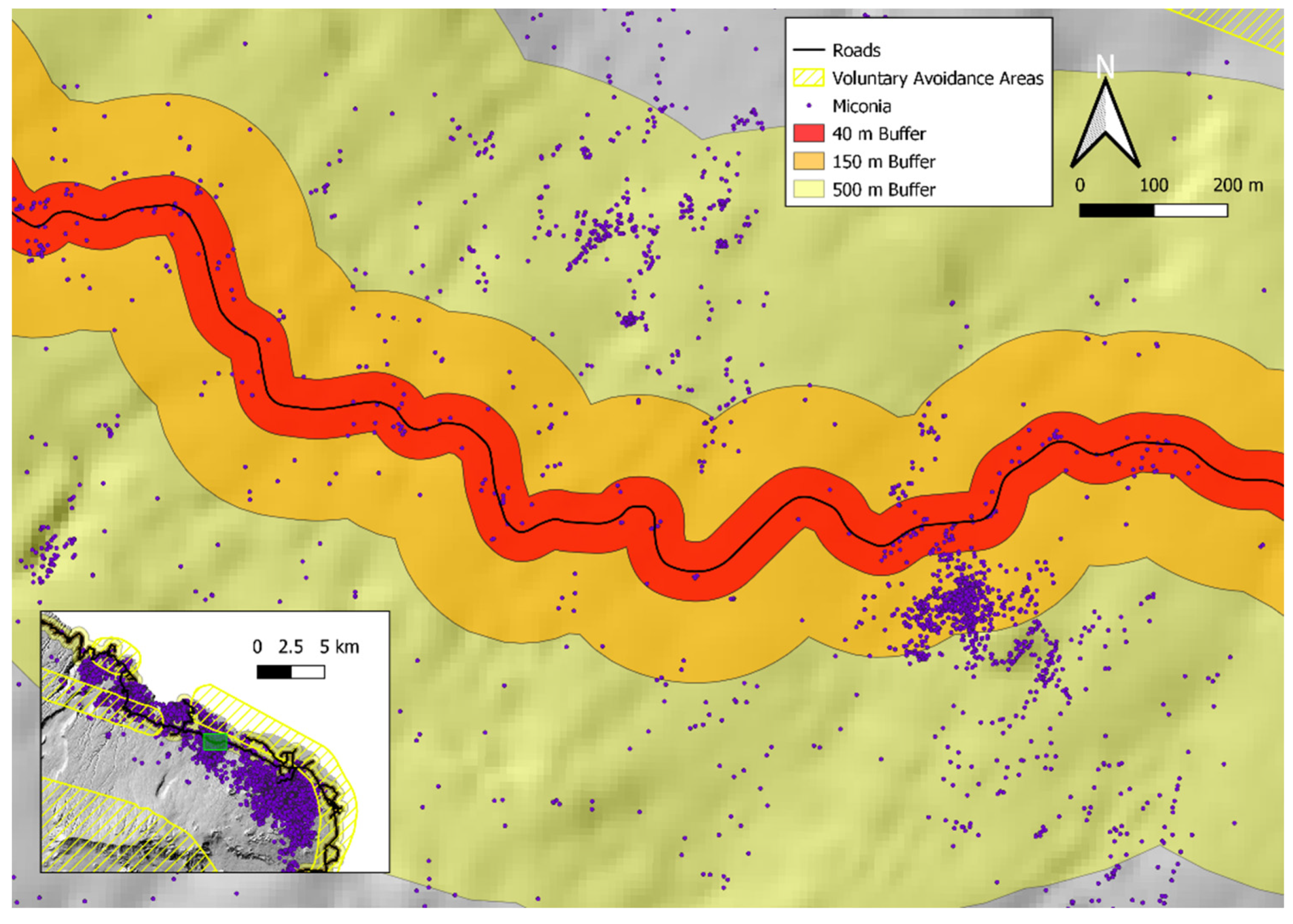
The need for a takeoff/landing area that is free of obstructions limits the potential area that the HBT-UAS could be deployed from. Roadsides constitute the most likely area for these operations to take place. To consider the impacts of the implementation of the HBT-UAS on miconia management of the island of Maui, we estimated of the number of plants that could be treated and the amount of voluntary avoidance area that could be covered by creating buffers based on theoretical ranges. We considered three ranges: (1) 40 m range of the prototype HBT-UAS, (2) 150 m range due to visual line of sight, and (3) 500 m limit of radio range. The 40 m buffer is based on the current battery limitations of the UAS we evaluated. The 150 m range is based on the current requirements for visual line of sight as stated in 14 CFR §107.31. The 500 m range is based on the maximum range of the radios listed by the manufacturer. Buffers were generated around available roads [47] and the number of miconia plants within the buffer and overlap with the voluntary avoidance areas were calculated (Figure 14 and Table 5).
While the limitations of the developed system would result in limited benefits due to the small range, these are high priority targets due to the increased risk for stochastic dispersal from human-mediated traffic on the road. Improved ranges up to visual line of sight are possible by transitioning to an alternative higher performance UAS. Heavy lift, beyond visual line of sight UAS have rapidly developed as package delivery operations receive additional attention [48,49]. Multiple technologies have been proposed to provide situational awareness during beyond visual line of sight operations [50,51,52,53,54]. Operation of the HBT-UAS beyond visual line of sight would face substantial safety obstacles, especially in the intended area where response to an inflight emergency or a crash is limited, however, the potential to cover over 20% of known plants and over 50% of voluntary avoidance areas represents a substantial asset to natural resource managers. While these metrics are for miconia, additional invasive species that can be treated with HBT include strawberry guava (Psidium cattleyanum), banana poka (Passiflora mollisima), Australian tree fern (Cyathea cooperi) and Kahili ginger (Hedychium gardnerianum) [40,55]. The adoption of HBT-UAS to supplement manned helicopter operations would enable greater focus of manned surveillance efforts in areas that are inaccessible to UAS and reduce environmental impacts from helicopter operations.
6. Conclusions
In conclusion, the effects of the payload on flight stability in autonomous flight are compensated by the flight controller but the added weight substantially reduces the available flight time. Projectile dispersal is within limits to reliably target individual branching points to treat an individual miconia plant. Future work to be undertaken includes investigation of alternative UAS and operational testing. Used in conjunction with UAS surveillance technologies for miconia [13], the HBT-UAS provides an alternative to ground and aerial invasive species management operations in many areas, especially where dense forest and noise abatement procedures preclude helicopter operations.
Author Contributions
Conceptualization, R.R. and J.J.K.L.; methodology, R.R.; validation, R.R. formal analysis, R.R.; investigation, R.R.; resources, D.M.J. and J.J.K.L.; data curation, R.R.; writing—original draft preparation, R.R.; writing—review and editing, D.M.J. and J.J.K.L.; visualization, R.R.; supervision, D.M.J. and J.J.K.L.; project administration, J.J.K.L.; funding acquisition, J.J.K.L. All authors have read and agreed to the published version of the manuscript.
Funding
This research was funded by the Hawaii Invasive Species Council, USDA Hatch Act Formula Grant H1132 and the USDA Renewable Resources Extension Act.
Data Availability Statement
An archive of developed software tool is provided in the Zenodo repository https://zenodo.org/record/5912029, accessed on 20 December 2021 (doi:10.5281/zenodo.5912029).
Acknowledgments
The authors would like to the thank our partner Tippmann Sports for their work in designing and fabricating the gimbal-marker system.
Conflicts of Interest
The authors declare no conflict of interest.
References
- Dawson, W.; Moser, D.; van Kleunen, M.; Kreft, H.; Pergl, J.; Pyšek, P.; Weigelt, P.; Winter, M.; Lenzner, B.; Blackburn, T.M.; et al. Global hotspots and correlates of alien species richness across taxonomic groups. Nat. Ecol. Evol. 2017, 1, 1–7. [Google Scholar] [CrossRef]
- Trauernicht, C.; Pickett, E.; Giardina, C.P.; Litton, C.M.; Cordell, S.; Beavers, A. The contemporary scale and context of wildfire in Hawai’i. Pac. Sci. 2015, 69, 427–444. [Google Scholar] [CrossRef]
- Hughes, R.F.; Asner, G.P.; Mascaro, J.; Uowolo, A.; Baldwin, J. Carbon storage landscapes of lowland Hawaii: The role of native and invasive species through space and time. Ecol. Appl. 2014, 24, 716–731. [Google Scholar] [CrossRef] [PubMed]
- Cavaleri, M.A.; Ostertag, R.; Cordell, S.; Sack, L. Native trees show conservative water use relative to invasive trees: Results from a removal experiment in a Hawaiian Wet Forest. Conserv. Physiol. 2014, 2, cou016. [Google Scholar] [CrossRef] [PubMed] [Green Version]
- Gagné, B.H.; Loope, L.L.; Medeiros, A.C.; Anderson, S.J. Miconia calvescens: A threat to native forests of the Hawaiian Islands. Pac. Sci. 1992, 46, 390–391. [Google Scholar]
- Meyer, J.-Y.; Florence, J. Tahiti’s native flora endangered by the invasion of Miconia Calvescens DC. (Melastomataceae). J. Biogeogr. 1996, 23, 775–781. [Google Scholar] [CrossRef]
- Meyer, J.Y. Observations on the reproductive biology of Miconia Calvescens DC (Melastomataceae), an alien invasive tree on the Island of Tahiti (South Pacific Ocean). Biotropica 1998, 30, 609–624. [Google Scholar] [CrossRef]
- Bonnet, S.; Lisein, J.; Lejeune, P. Comparison of UAS photogrammetric products for tree detection and characterization of coniferous stands. Int. J. Remote Sens. 2017, 38, 5310–5337. [Google Scholar] [CrossRef]
- Goodbody, T.R.H.; Coops, N.C.; Marshall, P.L.; Tompalski, P.; Crawford, P. Unmanned aerial systems for precision forest inventory purposes: A review and case study. For. Chron. 2017, 93, 71–81. [Google Scholar] [CrossRef] [Green Version]
- Linchant, J.; Lisein, J.; Semeki, J.; Lejeune, P.; Vermeulen, C. Are unmanned aircraft systems (UASs) the future of wildlife monitoring? A review of accomplishments and challenges. Mammal Rev. 2015, 45, 239–252. [Google Scholar] [CrossRef]
- Pádua, L.; Vanko, J.; Hruška, J.; Adão, T.; Sousa, J.J.; Peres, E.; Morais, R. UAS, sensors, and data processing in agroforestry: A review towards practical applications. Int. J. Remote Sens. 2017, 38, 2349–2391. [Google Scholar] [CrossRef]
- Pádua, L.; Hruška, J.; Bessa, J.; Adão, T.; Martins, L.M.; Gonçalves, J.A.; Peres, E.; Sousa, A.M.R.; Castro, J.P.; Sousa, J.J. Multi-temporal analysis of forestry and coastal environments using UASs. Remote Sens. 2018, 10, 24. [Google Scholar] [CrossRef] [Green Version]
- Perroy, R.L.; Sullivan, T.; Stephenson, N. Assessing the impacts of canopy openness and flight parameters on detecting a sub-canopy tropical invasive plant using a small unmanned aerial system. ISPRS J. Photogramm. Remote Sens. 2017, 125, 174–183. [Google Scholar] [CrossRef]
- Perroy, R.L.; Hughes, M.; Keith, L.M.; Collier, E.; Sullivan, T.; Low, G. Examining the utility of visible near-infrared and optical remote sensing for the early detection of rapid ‘Ōhi‘a death. Remote Sens. 2020, 12, 1846. [Google Scholar] [CrossRef]
- Rodriguez, R., III; Perroy, R.L.; Leary, J.; Jenkins, D.; Panoff, M.; Mandel, T.; Perez, P. Comparing interpretation of high-resolution aerial imagery by humans and artificial intelligence to detect an invasive tree species. Remote Sens. 2021, 13, 3503. [Google Scholar] [CrossRef]
- Shen, X.; Cao, L.; Yang, B.; Xu, Z.; Wang, G. Estimation of forest structural attributes using spectral indices and point clouds from UAS-based multispectral and RGB imageries. Remote Sens. 2019, 11, 800. [Google Scholar] [CrossRef] [Green Version]
- Wang, L.; Zhou, Y.; Hu, Q.; Tang, Z.; Ge, Y.; Smith, A.; Awada, T.; Shi, Y. Early detection of encroaching woody juniperus virginiana and its classification in multi-species forest using UAS imagery and semantic segmentation algorithms. Remote Sens. 2021, 13, 1975. [Google Scholar] [CrossRef]
- Yilmaz, C.S.; Yilmaz, V.; Gungor, O. Using UAS-based point clouds to generate high resolution digital terrain model for forestry research and applications. Eur. J. For. Eng. 2016, 2, 35–40. [Google Scholar]
- Merz, T.; Hrabar, S.; Kendoul, F.; Jeffery, M. Unmanned helicopter system for miconia weed surveys. In Proceedings of the 20th Australasian Weeds Conference, Perth, Australia, 11–15 September 2016; Weeds Society of Western Australia: Perth, Australia, 2016; pp. 191–194. [Google Scholar]
- Department of Transportation Airports Division. Hawaii Airports and Flying Safety Guide, 5th ed.; State of Hawaii, Department of Transportation Airports Division: Honolulu, HI, USA, 2013. [Google Scholar]
- Rodriguez, R., III. Perspective: Agricultural aerial application with unmanned aircraft systems: Current regulatory framework and analysis of operators in the United States. Trans. ASABE 2021, 64, 1475–1481. [Google Scholar] [CrossRef]
- Marshall, D.M. UAS regulations, standards, and guidance. In Introduction to Unmanned Aircraft Systems; CRC Press: Boca Raton, FL, USA, 2021; pp. 101–136. [Google Scholar]
- Shockley, J.; Dillon, C.; Lowenberg-DeBoer, J.; Mark, T. How will regulation influence commercial viability of autonomous equipment in US production agriculture? Appl. Econ. Perspect. Policy 2021, 1–14. [Google Scholar] [CrossRef]
- Ahmad, F.; Qiu, B.; Dong, X.; Ma, J.; Huang, X.; Ahmed, S.; Ali Chandio, F. Effect of operational parameters of UAV sprayer on spray deposition pattern in target and off-target zones during outer field weed control application. Comput. Electron. Agric. 2020, 172, 105350. [Google Scholar] [CrossRef]
- Giles, D.K.; Billing, R. Unmanned aerial platforms for spraying: Deployment and performance. Asp. Appl. Biol. 2014, 122, 63–69. [Google Scholar]
- Giles, D.; Billing, R. Deployment and performance of a UAV for crop spraying. Chem. Eng. Trans. 2015, 44, 307–312. [Google Scholar] [CrossRef]
- Li, X.; Giles, D.K.; Andaloro, J.T.; Long, R.; Lang, E.B.; Watson, L.J.; Qandah, I. Comparison of UAV and fixed-wing aerial application for alfalfa insect pest control: Evaluating efficacy, residues, and spray quality. Pest Manag. Sci. 2021, 77, 4980–4992. [Google Scholar] [CrossRef]
- He, L.; Wang, G.B.; Hu, T.; Meng, Y.H.; Yan, X.J.; Yuan, H.Z. Influences of spray adjuvants and spray volume on the droplet deposition distribution with unmanned aerial vehicle (UAV) spraying on rice. J. Plant Prot. 2017, 44, 1046–1052. [Google Scholar]
- Martinez-Guanter, J.; Agüera, P.; Agüera, J.; Pérez-Ruiz, M. Spray and economics assessment of a UAV-based ultra-low-volume application in olive and citrus orchards. Precis. Agric. 2020, 21, 226–243. [Google Scholar] [CrossRef]
- Zhang, P.; Lv, Q.; Yi, S.L.; Liu, Y.; He, S.L.; Xie, R.J.; Zheng, Y.Q.; Pan, H.Y.; Deng, L. Evaluation of spraying effect using small unmanned aerial vehicle (UAV) in citrus orchard. J. Fruit Sci. 2016, 33, 34–42. [Google Scholar]
- Qin, W.; Xue, X.; Zhang, S.; Gu, W.; Wang, B. Droplet deposition and efficiency of fungicides sprayed with small UAV against wheat powdery mildew. Int. J. Agric. Biol. Eng. 2018, 11, 27–32. [Google Scholar] [CrossRef] [Green Version]
- Wang, G.; Lan, Y.; Qi, H.; Chen, P.; Hewitt, A.; Han, Y. Field evaluation of an unmanned aerial vehicle (UAV) sprayer: Effect of spray volume on deposition and the control of pests and disease in wheat. Pest Manag. Sci. 2019, 75, 1546–1555. [Google Scholar] [CrossRef]
- Wang, G.; Han, Y.; Li, X.; Andaloro, J.; Chen, P.; Hoffmann, W.C.; Han, X.; Chen, S.; Lan, Y. Field evaluation of spray drift and environmental impact using an agricultural unmanned aerial vehicle (UAV) sprayer. Sci. Total Environ. 2020, 737, 139793. [Google Scholar] [CrossRef]
- Zheng, Y.J.; Yang, S.H.; Zhao, C.J.; Chen, L.P.; Lan, Y.B.; Yu, T. Modelling operation parameters of UAV on spray effects at different growth stages of corns. Int. J. Agric. Biol. Eng. 2017, 10, 57–66. [Google Scholar] [CrossRef]
- Hunter, J.E.; Gannon, T.W.; Richardson, R.J.; Yelverton, F.H.; Leon, R.G. Integration of remote-weed mapping and an autonomous spraying unmanned aerial vehicle for site-specific weed management. Pest Manag. Sci. 2020, 76, 1386–1392. [Google Scholar] [CrossRef] [Green Version]
- Khan, S.; Tufail, M.; Khan, M.T.; Khan, Z.A.; Iqbal, J.; Wasim, A. Real-time recognition of spraying area for UAV sprayers using a deep learning approach. PLoS ONE 2021, 16, e0249436. [Google Scholar] [CrossRef]
- Richardson, B.; Rolando, C.A.; Kimberley, M.O. Quantifying spray deposition from a UAV configured for spot spray applications to individual plants. Trans. ASABE 2020, 63, 1049–1058. [Google Scholar] [CrossRef]
- Leary, J.; Gooding, J.; Chapman, J.; Radford, A.; Mahnken, B.V.; Cox, L.J. Calibration of an herbicide ballistic technology (HBT) helicopter platform targeting Miconia Calvescens in Hawaii. Invasive Plant Sci. Manag. 2013, 6, 292–303. [Google Scholar] [CrossRef]
- Leary, J.; Mahnken, B.V.; Cox, L.J.; Radford, A.; Yanagida, J.; Penniman, T.; Duffy, D.C.; Gooding, J. Reducing nascent miconia (Miconia Calvescens) patches with an accelerated intervention strategy utilizing herbicide ballistic technology. Invasive Plant Sci. Manag. 2014, 7, 164–175. [Google Scholar] [CrossRef]
- Nelson Paint Company. HBT-G4U200 with Garlon 4 Ultra, EPA Reg. No. HI-120001; Nelson Paint Company: Kingsford, MI, USA, 2021. [Google Scholar]
- Rohrbach, Z.J.; Buresh, T.R.; Madsen, M.J. Modeling the exit velocity of a compressed air cannon. Am. J. Phys. 2012, 80, 24–26. [Google Scholar] [CrossRef]
- Robinson, G.; Robinson, I. The motion of an arbitrarily rotating spherical projectile and its application to ball games. Phys. Scr. 2013, 88, 18101. [Google Scholar] [CrossRef] [Green Version]
- Virtanen, P.; Gommers, R.; Oliphant, T.E.; Haberland, M.; Reddy, T.; Cournapeau, D.; Burovski, E.; Peterson, P.; Weckesser, W.; Bright, J.; et al. SciPy 1.0: Fundamental algorithms for scientific computing in Python. Nat. Methods 2020, 17, 261–272. [Google Scholar] [CrossRef] [Green Version]
- R Core Team. R: A Language and Environment for Statistical Computing; R Foundation for Statistical Computing: Vienna, Austria, 2019. [Google Scholar]
- Fazio, P.J. Projectile Dispersion of Marker Ball Launcher; Army Research Laboratory Aberdeen Proving Ground: Aberdeen Proving Ground, MD, USA, 2004; pp. 1–13. [Google Scholar]
- Garner, J.; Bundy, M. Paintball Accuracy Measurements; U.S. Army Research Laboratory Weapons and Materials Research Directorate: Adelphi, MD, USA, 2007; pp. 1–10. [Google Scholar]
- Maui County. Roads for the Islands of Maui, Molokai, Lanai and Kahoolawe as of 2018; Hawaii Statewide GIS Program Office of Planning: Honolulu, HI, USA, 2018. [Google Scholar]
- Pak, H. Use-cases for heavy lift unmanned cargo aircraft. In Automated Low-Altitude Air Delivery: Towards Autonomous Cargo Transportation with Drones; Dauer, J.C., Ed.; Springer International Publishing: Cham, Germany, 2022; pp. 49–72. ISBN 978-3-030-83144-8. [Google Scholar]
- Liebhardt, B.; Pertz, J. Automated cargo delivery in low altitudes: Business cases and operating models. In Automated Low-Altitude Air Delivery: Towards Autonomous Cargo Transportation with Drones; Dauer, J.C., Ed.; Springer International Publishing: Cham, Germany, 2022; pp. 73–104. ISBN 978-3-030-83144-8. [Google Scholar]
- Davies, L.; Bolam, R.C.; Vagapov, Y.; Anuchin, A. Review of unmanned aircraft system technologies to enable beyond visual line of sight (BVLOS) operations. In Proceedings of the 2018 International Conference on Electrical Power Drive Systems (ICEPDS), Novocherkassk, Russia, 3–6 October 2018; pp. 1–6. [Google Scholar]
- McAree, O.; Aitken, J.M.; Veres, S.M. Quantifying situation awareness for small, unmanned aircraft: Towards routine beyond visual line of sight operations. Aeronaut. J. 2018, 122, 733–746. [Google Scholar] [CrossRef] [Green Version]
- Güldenring, J.; Gorczak, P.; Eckermann, F.; Patchou, M.; Tiemann, J.; Kurtz, F.; Wietfeld, C. Reliable long-range multi-link communication for unmanned search and rescue aircraft systems in beyond visual line of sight operation. Drones 2020, 4, 16. [Google Scholar] [CrossRef]
- Ivancic, W.D.; Kerczewski, R.J.; Murawski, R.W.; Matheou, K.; Downey, A.N. Flying drones beyond visual line of sight using 4g LTE: Issues and concerns. In Proceedings of the 2019 Integrated Communications, Navigation and Surveillance Conference (ICNS), Herndon, VA, USA, 9–11 April 2019; pp. 1–13. [Google Scholar]
- Kato, N.; Kawamoto, Y.; Aneha, A.; Yaguchi, Y.; Miura, R.; Nakamura, H.; Kobayashi, M.; Henmi, T.; Akimoto, O.; Kamisawa, Y.; et al. Location awareness system for drones flying beyond visual line of sight exploiting the 400 MHz frequency band. IEEE Wirel. Commun. 2019, 26, 149–155. [Google Scholar] [CrossRef]
- Wilbur-Ellis Company. HBT-IMAZ, EPA Reg. No. HI-090004; Wilbur-Ellis Company: San Francisco, CA, USA, 2009. [Google Scholar]
Figure 1.
Map of detected miconia plants on the island of Maui. Approximately 10% of detected miconia occur in voluntary avoidance areas [20].
Figure 1.
Map of detected miconia plants on the island of Maui. Approximately 10% of detected miconia occur in voluntary avoidance areas [20].

Figure 2.
Four phases of HBT-UAS operation: (1) launch, (2) target acquisition, (3) treatment, and (4) return to launch site. Active personnel during each phase are colored green.
Figure 2.
Four phases of HBT-UAS operation: (1) launch, (2) target acquisition, (3) treatment, and (4) return to launch site. Active personnel during each phase are colored green.

Figure 3.
View from first person view video feed of HBT-UAS.
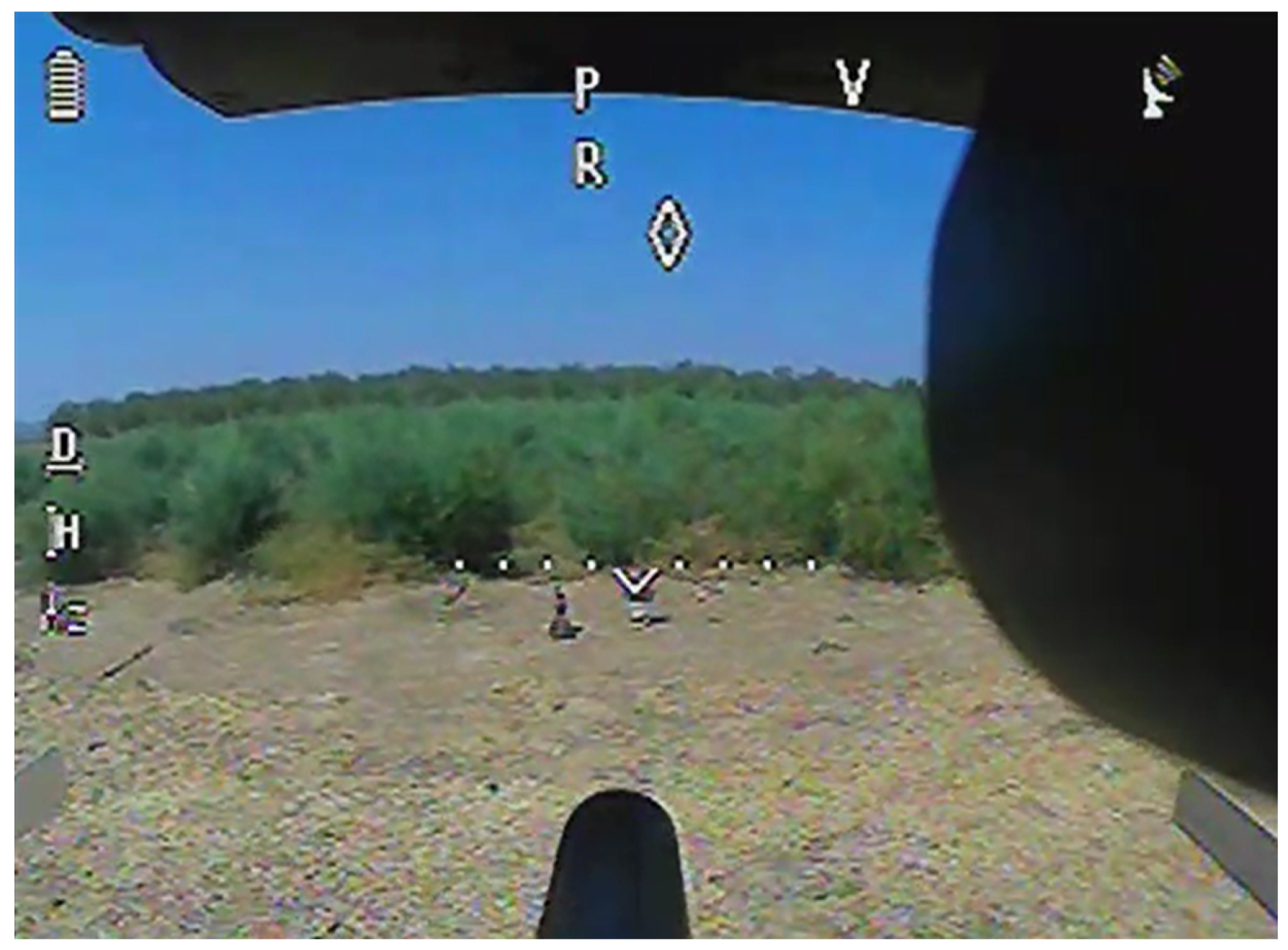
Figure 4.
(A) Gimbal marker system with major components labeled. (B) HBT-UAS in flight.

Figure 5.
Schematic of properties and forces of projectile propulsion in the barrel of the HBT-UAS.

Figure 6.
Forces acting on projectile after leaving the barrel. Lift is caused by the “Magnus” effect of the projectile spinning through the viscous fluid.
Figure 6.
Forces acting on projectile after leaving the barrel. Lift is caused by the “Magnus” effect of the projectile spinning through the viscous fluid.
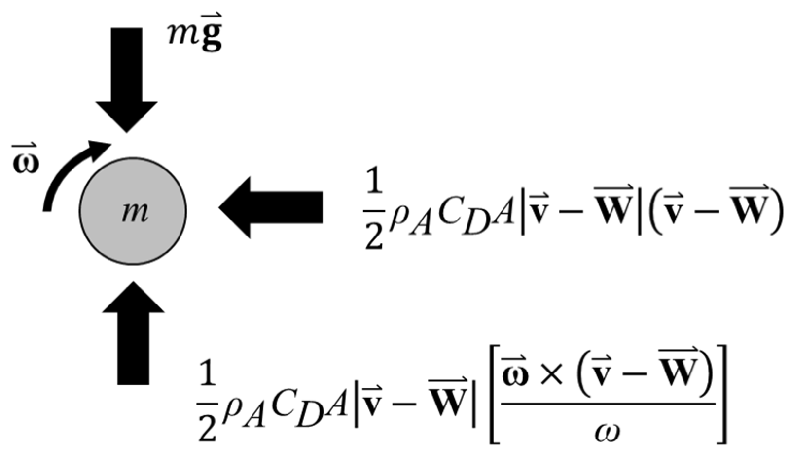
Figure 7.
(A) Simulation of velocity of projectile as it travels through the barrel results in predicted exit velocity of 81.76 m/s (white circle) from the barrel of the custom HBT marker. (B) Simulation of the trajectory of the projectile after it leaves a horizontally aligned barrel with positioned locations of targets relative to the marker barrel axis (vertical position 0) during experimental validation indicated by white circles.
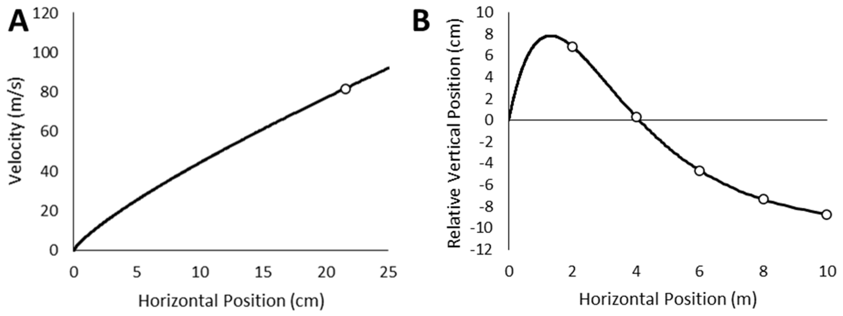
Figure 8.
Planned flight path to evaluate flight stability and battery draw for validation flights.

Figure 9.
(A) Experimental setup of target consisting of kraft paper pulled taut. (B) Exit holes in the Kraft paper are mapped using ImageJ with a tape measure used to calibrate the pixel size.
Figure 9.
(A) Experimental setup of target consisting of kraft paper pulled taut. (B) Exit holes in the Kraft paper are mapped using ImageJ with a tape measure used to calibrate the pixel size.
Figure 10.
(A) Horizontal deviation and (B) 3D deviation from planned flight path for control (red) and payload equipped (blue) aircraft. Results of pairwise t-tests of the means are shown for each phase of flight.
Figure 10.
(A) Horizontal deviation and (B) 3D deviation from planned flight path for control (red) and payload equipped (blue) aircraft. Results of pairwise t-tests of the means are shown for each phase of flight.

Figure 11.
Battery capacity for the programmed flight. Control flight is without payload. Note the large draw during the initial climb of the HBT equipped flight.
Figure 11.
Battery capacity for the programmed flight. Control flight is without payload. Note the large draw during the initial climb of the HBT equipped flight.

Figure 12.
CEP relative to aiming point (0,0) with distance from target indicated by color (2 m, blue; 4 m, red; 6 m, green; 8 m, purple; 10 m, yellow).
Figure 12.
CEP relative to aiming point (0,0) with distance from target indicated by color (2 m, blue; 4 m, red; 6 m, green; 8 m, purple; 10 m, yellow).
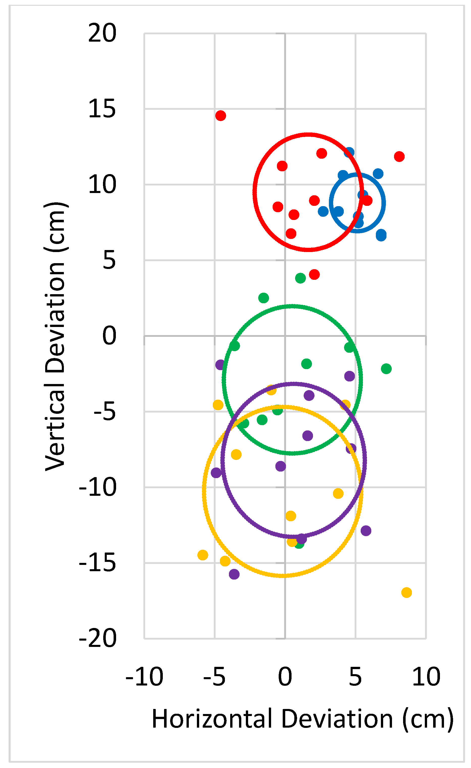
Figure 13.
Positions of projectile impacts (black circles) and local regression (black line) with standard error of the mean (gray) deviate from the positions initially predicted by the simulation (dashed line).
Figure 13.
Positions of projectile impacts (black circles) and local regression (black line) with standard error of the mean (gray) deviate from the positions initially predicted by the simulation (dashed line).
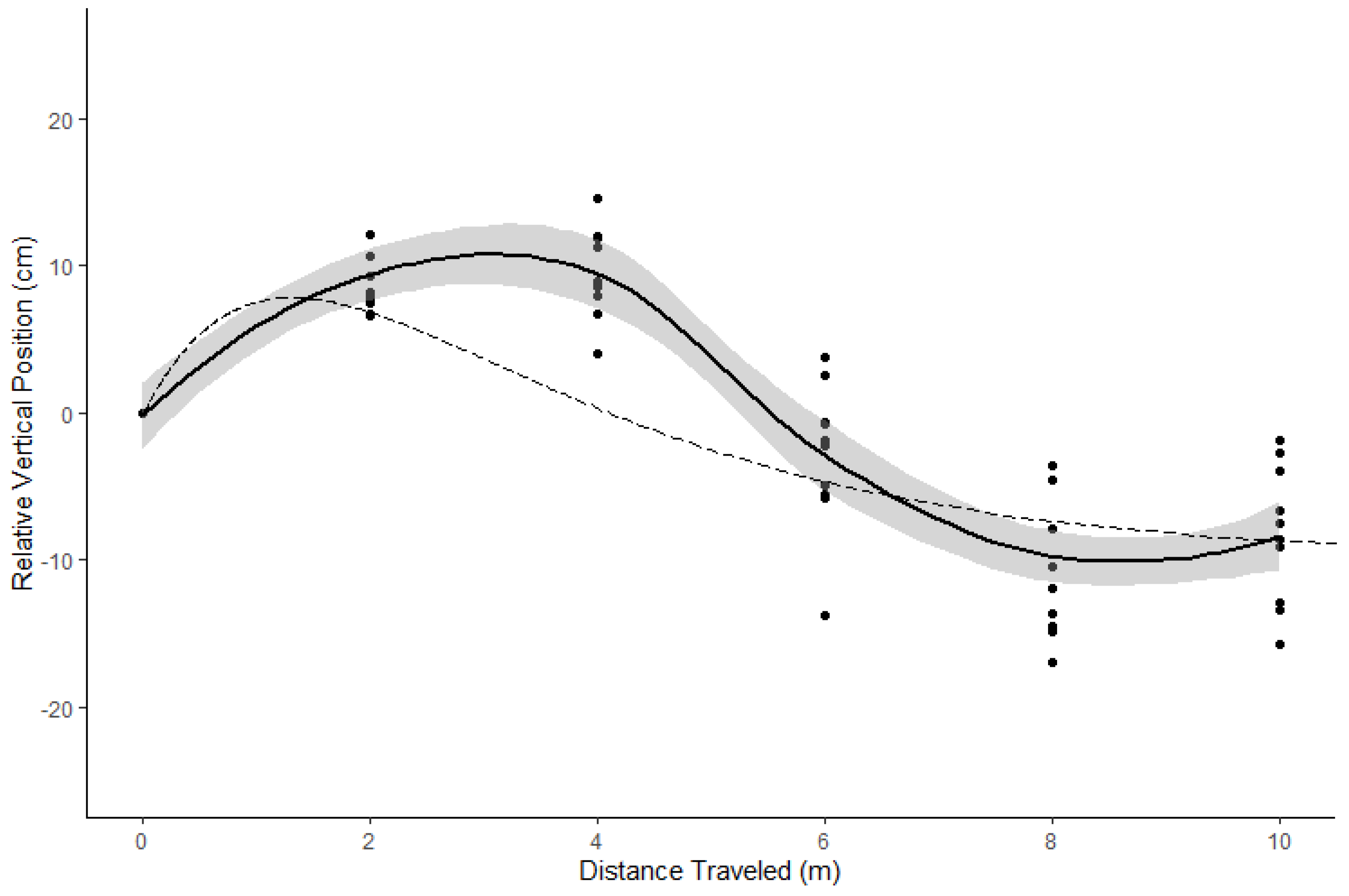
Figure 14.
Miconia points (purple circles) and voluntary avoidance area (yellow hash marks) within three buffers of available roads (40 m, red; 150 m, orange; 500 m, yellow).
Figure 14.
Miconia points (purple circles) and voluntary avoidance area (yellow hash marks) within three buffers of available roads (40 m, red; 150 m, orange; 500 m, yellow).

Table 1.
Model parameters for projectile trajectories from HBT-UAS.
| Parameter | Value (US) | Value (SI) | Parameter | Value (US) | Value (SI) |
|---|---|---|---|---|---|
| PR | 850 psi | 5.86 MPa | m | 0.106 oz | 3.00 g |
| V0 | 26 in3 | 0.426 L | L | 8.5 in | 21.6 cm |
| D | 0.689 in | 1.75 cm | T | 80.3 °F | 300 K |
Table 2.
ANOVA table of factors affecting horizontal deviation from programmed flight path.
| Factor | Sum of Squares | df | Mean Square | F | p | η2 |
|---|---|---|---|---|---|---|
| Phase | 911.5 | 3 | 303.83 | 2351.63 | <0.001 | 0.424 |
| Configuration | 9.9 | 1 | 9.90 | 76.62 | <0.001 | 0.005 |
| Residuals | 1228.8 | 9511 | 0.13 |
Table 3.
ANOVA table of factors affecting three-dimensional deviation from programmed flight path.
| Factor | Sum of Squares | df | Mean Square | F | p | η2 |
|---|---|---|---|---|---|---|
| Phase | 53,306 | 3 | 17,769 | 126.15 | <0.001 | 0.382 |
| Configuration | 1206 | 1 | 1206 | 8.56 | 0.003 | <0.001 |
| Residuals | 1,339,615 | 9511 | 141 |
Table 4.
CEP and RMSD of projectiles (n = 10).
| Distance (m) | CEP (cm) | RMSD (cm) |
|---|---|---|
| 2 | 1.87 | 10.41 |
| 4 | 3.81 | 12.89 |
| 6 | 4.87 | 6.40 |
| 8 | 5.58 | 12.11 |
| 10 | 5.05 | 10.08 |
Table 5.
Number of miconia plants and amount of overlapping voluntary avoidance area within 40 m, 150 m, and 500 m buffers of roads.
Table 5.
Number of miconia plants and amount of overlapping voluntary avoidance area within 40 m, 150 m, and 500 m buffers of roads.
| Miconia | Voluntary Avoidance Area | |||
|---|---|---|---|---|
| Plants | (%) | Area (ha) | (%) | |
| Total | 138,297 | 64,329 | ||
| Within 40 m | 1627 | 1 | 7099 | 11 |
| Within 150 m | 8103 | 6 | 17,721 | 28 |
| Within 500 m | 30,423 | 22 | 32,395 | 50 |
Publisher’s Note: MDPI stays neutral with regard to jurisdictional claims in published maps and institutional affiliations. |
© 2022 by the authors. Licensee MDPI, Basel, Switzerland. This article is an open access article distributed under the terms and conditions of the Creative Commons Attribution (CC BY) license (https://creativecommons.org/licenses/by/4.0/).
Share and Cite
MDPI and ACS Style
Rodriguez, R.; Leary, J.J.K.; Jenkins, D.M. Herbicide Ballistic Technology for Unmanned Aircraft Systems. Robotics 2022, 11, 22. https://doi.org/10.3390/robotics11010022
AMA Style
Rodriguez R, Leary JJK, Jenkins DM. Herbicide Ballistic Technology for Unmanned Aircraft Systems. Robotics. 2022; 11(1):22. https://doi.org/10.3390/robotics11010022
Chicago/Turabian StyleRodriguez, Roberto, James J. K. Leary, and Daniel M. Jenkins. 2022. "Herbicide Ballistic Technology for Unmanned Aircraft Systems" Robotics 11, no. 1: 22. https://doi.org/10.3390/robotics11010022
Note that from the first issue of 2016, this journal uses article numbers instead of page numbers. See further details here.