

Design and Evaluation of an Intuitive Haptic Teleoperation Control System for 6-DoF Industrial Manipulators

1
Department of Mechanical Engineering, Diepenbeek Campus, University of Leuven, 3590 Diepenbeek, Belgium
2
FlandersMake@KU Leuven, 3001 Leuven, Belgium
*
Author to whom correspondence should be addressed.
Robotics 2023, 12(2), 54; https://doi.org/10.3390/robotics12020054
Submission received: 24 February 2023
/
Revised: 24 March 2023
/
Accepted: 27 March 2023
/
Published: 1 April 2023
(This article belongs to the Special Issue Immersive Teleoperation and AI)
Abstract
:Industrial robots are capable of performing automated tasks repeatedly, reliably and accurately. However, in some scenarios, human-in-the-loop control is required. In this case, having an intuitive system for moving the robot within the working environment is crucial. Additionally, the operator should be aided by sensory feedback to obtain a user-friendly robot control system. Haptic feedback is one way of achieving such a system. This paper designs and assesses an intuitive teleoperation system for controlling an industrial 6-DoF robotic manipulator using a Geomagic Touch haptic interface. The system utilises both virtual environment-induced and physical sensor-induced haptic feedback to provide the user with both a higher amount of environmental awareness and additional safety while manoeuvering the robot within its working area. Different tests show that the system is capable of fully stopping the manipulator without colliding with the environment, and preventing it from entering singularity states with Cartesian end effector velocities of up to 0.25 m/s. Additionally, an operator is capable of executing low-tolerance end effector positioning tasks (∼0.5 mm) with high-frequency control of the robot (∼100 Hz). Fourteen inexperienced volunteers were asked to perform a typical object removal and writing task to gauge the intuitiveness of the system. It was found that when repeating the same test for a second time, the participants performed 22.2% faster on average. The results for the second attempt also became significantly more consistent between participants, as the inter quartile range dropped by 82.7% (from 52 s on the first attempt to 9 s on the second).
1. Introduction
Many robotic applications within industrial sectors aim for fully autonomous, human-free operation. Indeed, using robots for repetitive tasks brings the benefits of continuous execution, with minimal to no human intervention, reducing human error and increasing throughput. However, specific tasks are not possible to fully automate, or are so rare or special that the time and money spent on researching or programming their full automation is simply not worth the investment. In other instances, such as in surgical operations [1,2,3], the expertise of the human operator is required. Lastly, in application areas with volatile working environments such as nuclear research, tele-operated robots are a necessity to keep working conditions safe for humans, as in [4] where Tokatli et al. use robotic arms via glove-port teleoperation for performing research in high-radiation glovebox environments, or [5] where the authors use tele-operated robots for maintenance tasks in a nuclear fuel reprocessing plant. In these cases, a teleoperation system could be used to combine the benefits of having a human operator perform the task at hand, and those of using a robust industrial robotic manipulator. More generally, in [6] Ghosh et al. describe how Remotely Instructed Robots (RIRs) can be used to strike a balance between operator interaction and autonomy as they rely on both high and low level instructions from the operator.
However, the control and movement of the robot should be sufficiently user-friendly and intuitive for the operator to effectively take control of the robot for performing highly accurate and complex tasks. When executing a task by hand, a human operator has many sensory inputs such as vision, hearing, touch, etc. With teleoperation, many of these inputs are not as easy to convey accurately. One such way of achieving this is by the use of haptic feedback. By using this technique, it is possible to simulate the sense of touch to the user, allowing the user to “feel what the robot feels”, or give the operator a better sense of tele-presence in the working environment.
In this paper, the design and evaluation of a system for intuitive teleoperation is proposed, making it possible for operators to perform highly accurate and precise manual tasks using the strengths of robotic manipulation, while providing additional safety to the operator, the robot and the environment. The control system monitors the latest state of the robot and its virtual environment continuously. It adapts the input given by the user to prevent him or her from sending the robot into a singularity or collision state. It is also possible for the user to add “restricted zones” within the working environment, although this functionality is still work-in-progress. Virtual environment-induced haptic feedback and physical sensor-induced haptic feedback are implemented via data obtained from the virtual environment and a mounted force-torque sensor respectively. The former is used to increase the sense of tele-presence by applying a force to the user when the user manipulates the robot in the neighbourhood of virtual environmental collision objects such as walls, tables, or other modelled items. The latter is meant to further optimise specific tasks with the addition of haptics.
Related Work
Sensory feedback implementation in teleoperation systems is already researched in various fields. Abdeldjallil et al. utilises VR instead of haptics as a component of the intuitive teleoperation system as visual feedback [7] in the Vicarios interface. It allows the user to view the robot and task from any angle they choose by “teleporting” to any desired position. The new relative displacement of the user compared to the robot is automatically transformed to the robot base frame. To test this setup, participants were asked to pick up a tennis ball and deposit it in a cylindrical holder. It was shown that the average success rate increased from 62.50 ± 14.90% to 90.00 ± 5.30% compared to the baseline condition using a real-time stereo video feed.
Lima et al. [8] implemented an increased perception of grasping during object manipulation by utilising a Geomagic Touch X haptic interface [9] in combination with a V-REP physics simulation to simulate added “weight” to the tele-manipulation when the user picks up an object by applying force feedback when the object is grasped. They tested their system both in simulation and with a real robot by a group of participants. In their tests, all participants found that this implementation of force feedback had a positive effect during object manipulation tasks.
In contrast, Argin et al. [10] make use of haptics to further aid an operator during a peg-in-hole task. Here, haptics are used in two stages. When the manipulator is holding the peg, virtual spring-damper models are utilised to induce a feeling of inertia to the user. Additionally, when the peg comes in close approximation to the hole, a second coupling is utilised to aid in guiding the peg towards the hole, facilitating an easier alignment of the peg and the hole. In this study, it was found that the haptic coupling reduced the total teleoperation time for all four test subjects. On average, the operation time was reduced from 77.54 s to 65.23 s.
To conclude, Bimbo et al. [11] make use of haptic feedback via wearable vibrotactile bracelets for added telepresence in cluttered environments. These bracelets are placed on the operators arm and vibrate at the corresponding location when the robot comes into contact with an object, indicating collision. Their test setup is comprised of various objects with different sizes, shapes and stiffnesses. A grasping object (ball) is placed randomly and hidden in this environment. A participant is then asked to locate and grasp the object using the vibrotactile bracelets and a video feed provided by a wrist mounted camera on the robot. Their results depict an average success rate increase of 111% when using the vibrotactile feedback compared to the same system without haptics. Furthermore, the measured forces and torques exerted on the environment were significantly lower.
In contrast to the related work, the system proposed in this article improves intuitiveness during teleoperation by haptic feedback from real-world force measurements from a wrist-mounted force-torque sensor and from virtual environment input, while also monitoring the state of both the robot and the environment in real-time and adjusting the motion command given to the robot according to distance and Jacobian measurements in the virtual workspace to fully prevent collisions and singularity states. Whereas many of the examples in related work use haptics to futher optimise specific robot tasks [8,10], the proposed system also provides the user of a safer working environment via both an increased sense of environmental awareness due to the applied feedback and real-time command input monitoring which alters the given command to slow the manipulator down, only in the direction that is required. This way, the operator can use the robot with a better sense of control as only the required velocity components are altered, while simultaneously receiving haptic feedback from the controller. Similar to [11], haptics are used to indicate when the operator is in close proximity to collision objects. However, Bimbo et al. generate haptic feedback when the manipulator has already come into contact with the environment, which could potentially damage both the environment and the robot. The proposed system still generates feedback to indicate nearby collision objects, while preventing the manipulator from coming into contact with said objects for an increased level of safety.
2. Materials and Methods
The focus of this work is on industrial applications, using six-degree-of-freedom (DoF) robotic manipulators in environments known a priori. Common examples are a robot alongside a conveyor belt or in a work cell, handling pick-and-place style tasks, or automatic assembly/disassembly. To be more specific to our application, the robot should be capable of moving in a constraint, but known environment, taking the limits of the environment itself, and additional “restricted zones” where (part of) the robot is allowed to move only at limited velocities and accelerations into account. It should be capable of grasping and manipulating both stationary and dynamic objects ranging in size, shape and weight. The smallest of which can be described as a small cylindrical, peg-like object with an outer diameter and height of 8.00 ± 0.02 mm, which will be discussed in Section 3.
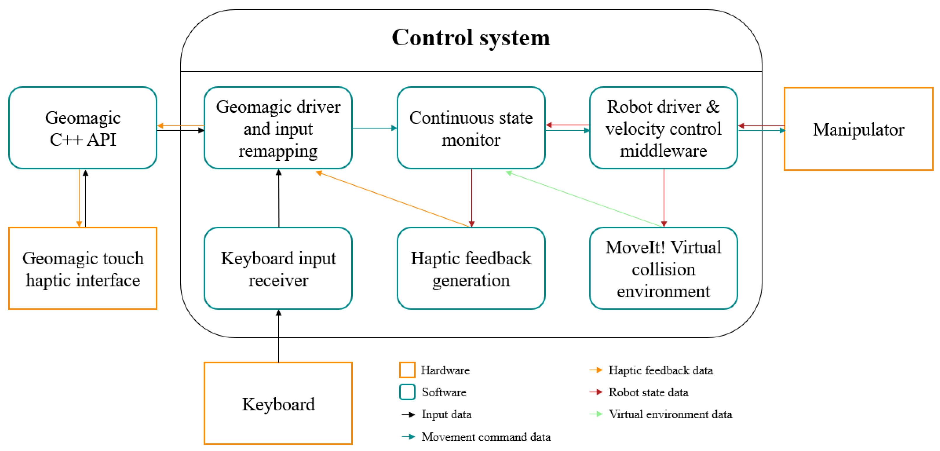
The teleoperation system functions by taking the input of a desired control interface, and using this to anticipate and calculate the future robot and environment state, which was dubbed the continuous state monitor. Then, based on this information, the input command is altered before sending the command to the robot controller. Force feedback is applied to the user if necessary. The full system diagram can be seen in Figure 1.
2.1. Interface Input
First, the input of the control interface is read and mapped to a twist message, which can be understood by the robot-control interface. This message type consists of Cartesian linear and angular x, y and z velocities expressed in a given reference frame. In theory, any control interface (also without haptics) can be used as long as it is translated to a Twist format, as this is what subsequent processing components regarding movement require. To be able to use haptic feedback, the Geomagic Touch haptic interface [12] was chosen for further development. The motivation behind the use of the Geomagic Touch is that it is the most affordable professional impedance haptic interface on the market. As shown in Figure 2, the device is designed as a 6-DoF link system with a pen-shaped end effector for the operator to handle. Thus, the pose of the tip of the pen can be monitored via forward kinematics using a Denavit–Hartenberg analysis of the link system. The forward kinematics are directly implemented in the Geomagic driver. The Touch also contains actuation in its first three joints. Using this, it can generate forces of up to 3.3 N with three degrees of freedom. The pen of the interface is equipped with two buttons, which can be pressed simultaneously with one finger. For added safety, in this application, movements are only processed if and only if both buttons on the pen are pressed and held. This prevents unwanted manipulator movements due to operator error such as accidentally dropping the pen.
To facilitate more user-friendly control, different control modes are added to tailor the movements of the robot to the specific situation. These modes are the proportional control mode and the velocity control mode.
In the proportional control mode, the pose of the tip of the Geomagic Touch is tracked from the point at which the buttons on the pen are pressed. This pose becomes the reference pose for all future movements until the operator lets go of the buttons and repositions the pen. In this operating mode, the end effector of the robot follows the relative displacement of the pen compared to the reference pose. This working mode is mostly designed for bridging large distances with the robotic arm.
In the velocity control mode, the robot only moves when the operator moves the pen of the Geomagic Touch. Where the proportional mode looks at the displacement between the reference pose and the current pose, the velocity mode takes the velocity of the pen into account as well. It scales the robot velocity according to the displacement between the current pose and the pose from one time step ago. When using this control mode, a “drag-and-drop” approach has to be taken instead of the continuous movement produced by the proportional control. Because of this, this mode is well-suited for highly accurate, fine tasks that require precise movements.
When switching between the proportional and velocity based control modes while the operator is still holding down the buttons of the controller (and the robot is thus still moving), the latest pose of the pen will be assumed as the new reference pose to prevent large, unwanted movements due to the control mode switch. The maximum Cartesian velocity of the robot is limited to a maximum of 0.25 m/s for operator and environment safety (which can be lowered by the user if this is desired via keyboard input).
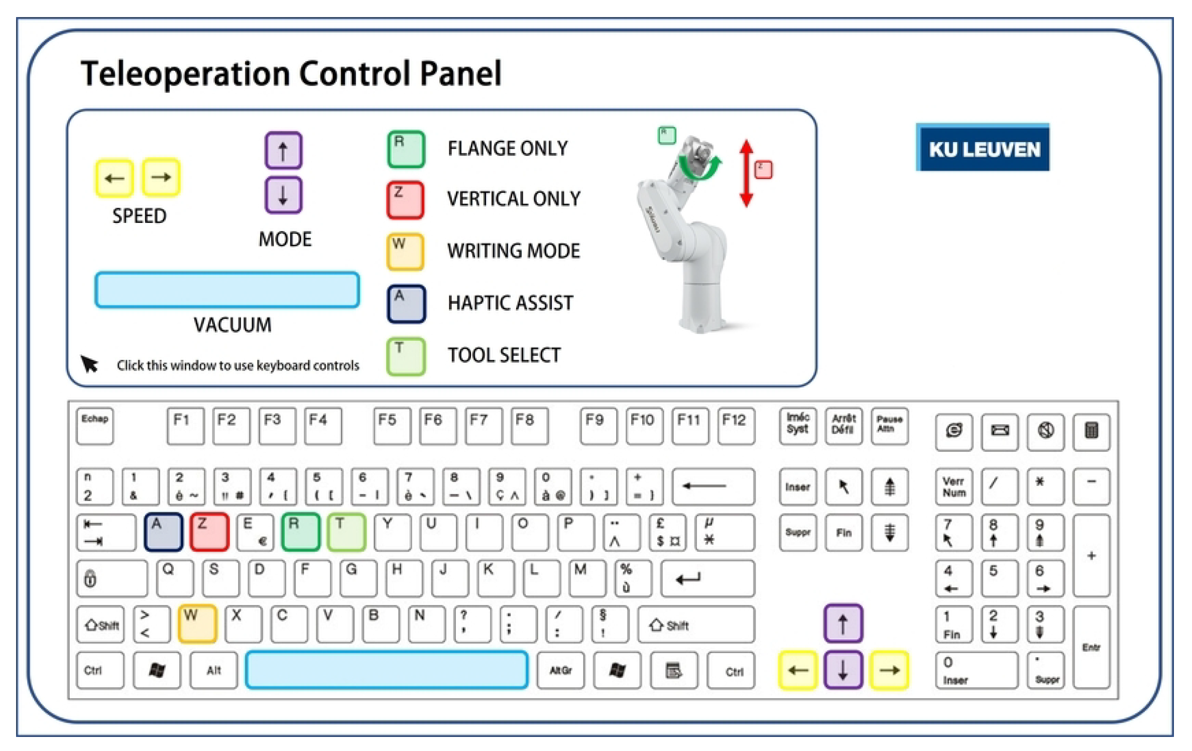
Both control modes are also further subdivided into different control options by allowing the user to lock and unlock specific parts of the control. This makes it possible to lock e.g., rotation or translation axes for easier task execution. These control options are displayed to the user via a heads-up-display (HUD) during operation, which is shown in Figure 3. Other options consist of altering the maximum allowed velocity of the robot, enabling and disabling vacuum, etc.
The user can, at any point, switch between these settings freely without halting the robot. The selection of the different working modes and settings are carried out via the keyboard of the host computer and fed to the Geomagic driver as shown by the system diagram in Figure 1.
2.2. Continuous State Monitor
The resulting Twist-type message generated by the Geomagic driver is passed into the continuous state monitor. This system uses this input to calculate and anticipate what the next state of the robot would be, and corrects the input command if necessary to prevent the user from sending the robot into collision or singularity states, or to apply additional constraints in restricted zones. The state of the robot and the virtual environment are monitored via MoveIt! [13]. If multiple prevention mechanisms are triggered the same time (e.g., the robot is close to collision and a singularity state), the system will compare the individual x, y and z velocities and choose the lowest of each.
2.2.1. Singularity Prevention
To start, singularity states are prevented by monitoring the Jacobian matrix of both the current robot state and the anticipated future robot state. As explained by Stejskal et al. in [14], a manipulator reaches a singular state when the determinant of the Jacobian matrix equals zero. To prevent this from happening, the determinant of the current-state Jacobian is compared to a determinant threshold-value. If the current absolute determinant value becomes lower than the threshold, the robot is nearing a singular state, and the singularity monitoring functionality takes action. Now, with each input the anticipated absolute value of the future determinant value is compared to the absolute value of the current determinant value. If the absolute value of the new, anticipated determinant is closer to zero than the current absolute value, the robot is moving closer to the singular state and its input velocity is altered according to Equation (1), decelerating the Cartesian input to a minimal velocity of 0.001 m/s. As Equation (2) never becomes zero, leaving out this minimal velocity value would result in an unsolvable situation. Furthermore, 0.001 m/s is the slowest velocity that can be processed by the robot controller. Different response equations were considered before deciding on the currently used altered sigmoid function. From the authors’ perspective, this function yields the smoothest and most effective robot response compared to either a linear, exponential or power law response curve.
With being the length of the input velocity vector, the current monitored determinant value and the determinant threshold value. To test the singularity prevention component of the continuous state monitor, an operator deliberately attempts to bring the robot into various different singularity states, at different velocities to find a relation between the Cartesian end effector velocity and the minimal required determinant threshold value. Here, it was found that in this setup, a value of 0.05 worked well for all velocities up to 0.25 m/s. Because of this, it was chosen to use 0.05 as a fixed value. However, in the future, the authors would like to re-evaluate this decision and look deeper into a dynamic determinant threshold similar to the distance threshold discussed in Section 2.2.2.
2.2.2. Collision Prevention
Next, to prevent collision states, the monitoring system uses a combination of the Flexible Collision Library (FCL) [15] and the Bullet physics engine [16] to continuously check the distance between the robot (with or without attached objects) and its (virtual) environment. Here, the virtual collision environment is assumed to be a highly accurate representation of the real-world environment in terms of object positioning, orientation and general collision geometry. FCL is used to compute the positions and distance between the nearest point of the robot and the environment. A distance threshold value is added, which indicates when the system has to start altering the input velocity as the manipulator moves towards a collision object. Simply using this distance value to rescale the robot velocity results in an unpleasant teleoperation system, as the robot is slowed down in every direction as long as it is within the threshold distance region, regardless of its movement direction. Only movement components along the normal direction of the surface and towards the surface should be taken into account. To achieve this, the nearest point data found by FCL are used to perform raycasting from the robot point to the environment point to extract the normal direction of the collision surface. This is visualised in Figure 4.
The input velocity command () can now be projected onto the normal direction () and deconstructed into a projected () component and a remaining () component as follows:
The projected component can be rescaled similar to Formula (1) prevention
with being the measured distance and the distance threshold value. This rescaled and projected velocity can now be added to the remaining component to form the full, rescaled velocity vector. Additionally, a hard-stop value lets the system fully stop the robot if the distance would become lower than this value. In our tests, this was set to 0.005 m, but can be specified for the task at hand via the configuration file. The newly rescaled velocity command is used to recalculate the anticipated robot state. If this state would be within the hard-stop range, the projected velocity component is removed completely, resulting in:
In contrast to the determinant threshold value, the distance threshold is programmed to dynamically change depending on the input velocity command. When the robot is moving at lower velocities, the input alteration can start closer to the collision surface while still stopping the robot in time. This relation is empirically determined by deliberately attempting to push the robot into collision states at different velocities up to 0.25 m/s, with varying threshold values. The lowest possible threshold value without the robot colliding is recorded for each velocity at 0.05 m/s intervals. These results are depicted in Figure 5. This resulted in the following quadratic formulation for the implementation of the dynamic threshold value:
2.2.3. Restricted Zones
Lastly, it is possible for the user to add collision meshes to the environment and map them as restricted zones. When the manipulator approaches such a zone, it is slowed down similar to the collision prevention, but to a pre-specified, customisable . Additionally, the user can specify which links and/or tools of the robot are allowed to enter the zone via the configuration file. This way, the robot remains controllable under additional environmental constraints. An example can be seen in Figure 6. The system will treat the zone as a regular collision object while the manipulator is approaching, but keeps track of the specified zone, tool and link data separately so collision between these objects can be ignored in further processing.
Although the restricted zone system is functional, the current implementation is computationally expensive and still in developements the induced latency couldake the system unstable. Reprogramming and optimisation of this functionality is therefore added as future work.
2.3. Haptic Feedback Generation
Haptic feedback is realised via two different methods: (A) Virtual environment-induced haptic feedback and (B) Physical sensor-induced haptic feedback.
In situation (A), virtual environment input from the digital collision environment is utilised. Safety walls, tables and other static collision objects (generated from STL files of the desired objects) in the virtual robot environment are taken into account by monitoring the distance between the manipulator and the collision environment as explained in Section 2.2. Once the measured distance value becomes lower than the force-distance threshold (which can be set separately from the distance threshold in the continuous state monitor), the controller will start exerting force to counteract the movement of the operator, according to the exponential function displayed in Figure 7, and given by:
with being the maximum allowed feedback force, which for this interface results in 3.3 N, the force exponential decay constant, chosen so that at the desired force-distance threshold, the exerted force will be ∼0.25 N as, on average, values lower were hardly noticed by volunteers. As an example, a distance threshold value of 0.100 m is assumed, resulting in a lambda value of −25.80 according to Formula (12).
In situation (B), an additional force-torque sensor is added to the robot end-effector to incorporate haptic feedback for specific task optimisation. In this paper, a Robotiq FT300 sensor [17] is used for all tests.
3. Results
3.1. Singularity and Collision Prevention
To test the robot response of both the singularity and collision blocking components of the continuous state monitoring system, the operator deliberately attempts to move the robot into a singularity or collision state. Figure 8 and Figure 9 visualise the input velocity commands as sent to the robot via the continuous state monitor (orange) and the actual end-effector velocity monitored via the real-time joint states of the robot when approaching a singularity and collision state respectively. For the sake of readability of the figures, only one of the velocity axes of the twist command is displayed in the figures.
Figure 8 shows that the robot follows the singularity velocity alteration accurately. From Figure 9, it can be observed that when the velocity change is more drastic to prevent collision with the environment, the robot responds within ±th to th of a second after receiving the velocity command, moving at an input velocity of 0.1 m/s.
3.2. Intuitiveness
To test the intuitiveness and user-friendliness of the system, a set of fourteen volunteers was asked to perform two independent tasks. The group consists of 11 male and 3 female participants, of whom 5 have experience with robot control. The nine other volunteers had no prior robotic experience to the authors’ knowledge. However, none of the participants had prior knowledge of the proposed system or its functionality. Both tasks are performed twice to gauge how much familiarity the users gain after one execution attempt.
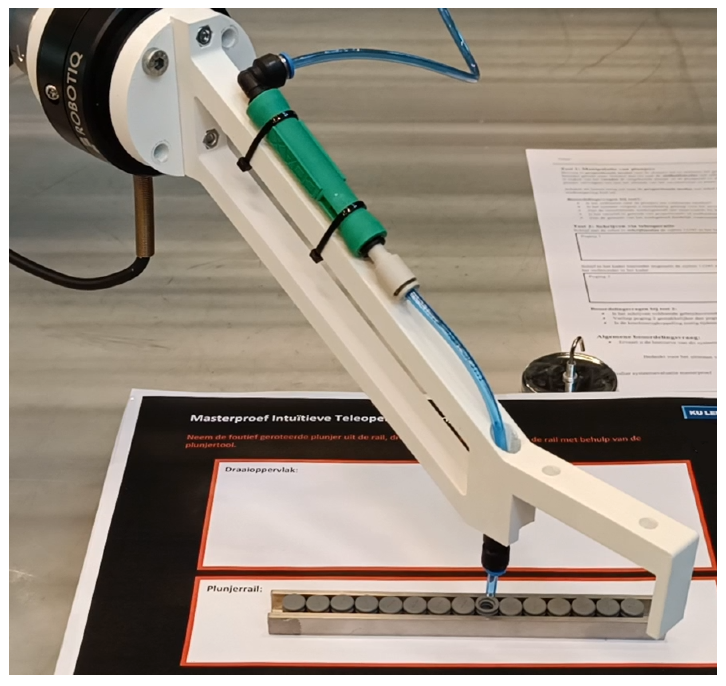
The first task is a simulation of a real-life objective within production. Here, a transport rail is assumed with an anomalous object that should be removed by the user using a specific robot tool, both displayed in Figure 10. The anomalous object being a small, peg-like object with an inner diameter measured at 4.50 mm (±0.02 mm). The tool tip consists of a 4 mm tube, able to pick up the anomalous object using vacuum generated by a venturi element within the tool. The users are asked to:
- Put the tool in the right orientation (Z-axis perpendicular to the table) and move the robot into the general area of the transport rail using the proportional mode;
- Switch to the velocity-based control and move the tip of the robot tool into the hole of the anomalous object for removal;
- Activate the vacuum of the tool, take out the object, put it down, turn it around and put it back in the rail in the correct orientation;
- Move away from the rail in any desired control mode.
The time for each attempt is measured to see if there is a noticeable improvement in the performance of the test subject with respect to the first time they perform the same task. It can be noticed in Table 1 and Figure 11 that out of all 14 volunteers, all except one see a small or significant improvement in how fast they can perform the task. Looking at the single participant who performed slightly slower, it can be noticed that in this case, the time difference is small to none, with a difference of 1 s (resulting in a performance decrease of 0.7%). In general, a mean performance increase of 22.8% can be noticed over all subjects combined.
Additionally, when representing these measurement data in a boxplot representation, as shown in Figure 12 with its data in Table A1, the gained familiarity with the system after one single execution becomes apparent. The inter quartile range (IQR) has reduced significantly going from 52 s to 9 s on the second attempt, resulting in a reduction of 82.7%. It can also be observed that the median of the second attempt is only 6 s longer than the fastest recorded time of the first attempt, while the slowest recorded time is reduced by 56 s or 36% going from 154 s to 98 s. Although there are two recorded times that are larger than 98 s, these can be seen as statistical outliers, using the definition of the minimum and maximum whisker value of a boxplot as:
where and stand for the value of the third quartile and the inter quartile range respectively. The distance between the maximum and minimum value has also dropped significantly going from 81 s to 34 s, resulting in a reduction of 58%.
To further analyse whether or not these results are statistically significant after removing the encountered outliers (participant seven and nine) from the data set, a paired t-test with a significance level of 0.05 is performed [18] The hypothesized mean difference is set to zero to verify if there is a true mean difference between attempt one and two. The results of the paired t-test can be found in Table 2. Looking at these results, both the p-value for two-tailed t-tests and the static t-value conclude that there is a statistically significant mean difference between the first and the second attempt. Firstly, a p-value of 0.001 is obtained, which is lower than the significance level of the t-test (0.05). Secondly, the absolute value of the static t-value (4.411) is larger than the critical t-value for two-tailed t-test (2.201).
Just like the first task, the second is modelled after a realistic objective within the industrial production environment. For many sampling applications, it is common to make additional annotations on the object. A different tool is attached to the robot to be able to hold a pen. The users are asked to write the numbers one through five on a piece of paper as shown in Figure 13 using a specialised, altered control mode of the robot specific for this task. Only forces along the Z-axis are utilised as these will change when the pen presses down on the paper. When the applied force exceeds a specified threshold value, the operator will not be able to move the robot tool down any further. An equivalent, scaled force will be applied back to the user along the interface’s Z-axis in the opposite direction to convey a sense of touch from the tip of the pen on the table. As an additional visual validation, the participants are also asked to write the numbers by hand to see how closely the teleoperation results resemble their natural handwriting.
From Figure 13, an improvement in readability can be observed going from the first to the second attempt. The second attempt also approaches the participant’s natural handwriting more closely, although this is a visual, subjective conclusion. Similar results can be observed for the other participants, whose writing results can be consulted in Appendix C.
After performing the tasks with the robot, all volunteers were asked to fill in a survey to gauge how they experienced the teleoperation system. It is comprised of a set of eight questions using the four-point Likert scale technique [19,20] similar to the approach of [8], where they also used the Likert scale with two four-point questions for 17 participants.
The following eight questions were asked:
- Do you find navigating towards the anomalous object intuitive?
- Is the system in your experience accurate enough to perform the task at hand?
- Do you find the different operation modes to be of added value for the execution of the task?
- Is the difference between proportional and velocity based control clear?
- Do you find the working area limitations useful?
- How intuitive do you find the system for writing (numbers)?
- Did you find the second attempt to be easier than the first?
- Is the force feedback a useful addition for this task?
For each question, the volunteers can indicate whether they experienced this aspect as either very negative, negative, positive, or very positive.
Looking at the results of this questionnaire in Table A2, it can be seen that the overall reception of the system can be seen as very positive to positive. On average, the answers very positive and positive were given 62.5% and 29.5% out of the total, while only 8% of the answers fall in the negative category. Moreover, the very negative option was never indicated by any of the users. These results are also visualised in Figure 14.
It can be noticed from these results that the users experienced the writing task as less intuitive than the object-removal task. When looking at the results for each task individually as shown in Figure 15, for the first task, people experienced the system as very positive, gaining 77.1% of the votes. With 20.0% and 2.9% going to positive and negative respectively. For the second task on the other hand, while people are still positive overall, a bigger variation in results can be seen as this task scored 38.1%, 45.2% and 16.7% on very positive, positive and negative respectively.
4. Conclusions
This paper presents a haptic teleoperation system for industrial 6-DoF robotic manipulators using a haptic interface. For validation, the Geomagic Touch controller was implemented.
The continuous state monitor system is capable of preventing both singularity states and collisions by using the input command given by the operator and the data from the measurements in the virtual working environment to anticipate the future robot state, and adapt the input command accordingly by rescaling the velocity via either Formula (1) or Formula (6). Haptics were realised via virtual environment input using measurement data of a virtual copy of the working environment, or physical sensor input from the mounted force-torque sensor. Using the distance measurements, force-feedback to the user is scaled according to Formula (11).
A group of 14 voluntary participants was asked to test the system by executing an object removal task and a writing task, both simulating real tasks in a production environment. The tasks were executed two times to gauge how much the participants performed better after one execution of the task to gain familiarity. For the object removal task, it was found that on the second attempt, an overall improvement of 22.8% could be observed. Moreover, the IQR of the measured times has decreased by 82.7%. A paired t-test further confirms the statistically significant mean difference between the first and second attempt after eliminating two outliers from the data set. For the writing task, it could be observed that the second writing attempt was in general more readable and closer to the user’s natural handwriting.
All participants were asked to fill out a questionnaire at the end where they could indicate how intuitive they perceived different parts of the system. Here, it was found that 92% of all answers fell in the Positive or Very positive category. From the questionnaire it can be derived that the second task was found to be less intuitive than the first. It can be concluded that on mean average, the participants experienced the system as being intuitive.
As future work, the authors would like to revisit the possibility of using a dynamic determinant threshold. Additionally as stated in Section 2.2.3, it is planned to further optimise and reprogram the restricted zone functionality for better overall performance, stability and usability. The authors would like to implement spring-damper models similar to [10] to take the robot’s dynamics into account more accurately. In the current setup, only the closest distance between the robot and the environment are taken into account. The authors would like to expand this with additional points to prevent the system from locking the manipulator in a local minimum. Although the user tests and paired t-test give an indication of the intuitiveness of the system, the authors would like to perform practical intuitiveness tests with larger group sizes to further gauge how intuitive the system is. Lastly, as this work focuses on performing a static task, additional work will be performed to also incorporate dynamic tasks.
Author Contributions
Conceptualization, I.D. and E.D.; methodology, I.D. and E.D.; software, I.D.; validation, I.D. and E.D.; formal analysis, I.D.; investigation, I.D.; resources, I.D., E.D. and K.K.; data curation, I.D.; writing—original draft preparation, I.D.; writing—review and editing, I.D., E.D. and K.K.; visualization, I.D.; supervision, E.D. and K.K.; project administration, E.D. and K.K.; funding acquisition, E.D. and K.K. All authors have read and agreed to the published version of the manuscript.
Funding
This research was funded by Flanders Innovation & Entrepeneurship Baekeland grant number HBC.2020.2884.
Informed Consent Statement
All subjects gave their informed consent for inclusion before they participated in this study.
Data Availability Statement
Not applicable.
Acknowledgments
The authors would like to thank the researchers at ACRO, master’s thesis students Robin Heleven and Wout Kenis, and Pfizer Puurs for their contributions.
Conflicts of Interest
The authors declare no conflict of interest. The funders had no role in the design of the study; in the collection, analyses, or interpretation of data; in the writing of the manuscript; or in the decision to publish the results.
Appendix A. Boxplot Data for Participants’ Test Results

Table A1.
Boxplot data for each attempt.
| Attempt 1 (s) | Attempt 2 (s) | |
|---|---|---|
| Minimum | 73 | 64 |
| First quartile | 89 | 75 |
| Median | 108 | 79 |
| Third quartile | 141 | 84 |
| Maximum | 154 | 98 |
| Inter Quartile Range (IQR) | 52 | 9 |
Appendix B. Users’ Questionnaire Response Results
Table A2.
Responses of volunteers to the proposed questionnaire in total number of votes and percentages.
Table A2.
Responses of volunteers to the proposed questionnaire in total number of votes and percentages.
| Question Nr. | Very Negative | Negative | Positive | Very Positive | |
|---|---|---|---|---|---|
| Question 1 | # of votes | 0 | 0 | 7 | 7 |
| Percentage | 0.0% | 0.0% | 50.0% | 50.0% | |
| Question 2 | # of votes | 0 | 0 | 1 | 13 |
| Percentage | 0.0% | 0.0% | 7.1% | 92.9% | |
| Question 3 | # of votes | 0 | 1 | 1 | 12 |
| Percentage | 0.0% | 7.1% | 7.1% | 85.7% | |
| Question 4 | # of votes | 0 | 0 | 3 | 11 |
| Percentage | 0.0% | 0.0% | 21.4% | 78.6% | |
| Question 5 | # of votes | 0 | 1 | 2 | 11 |
| Percentage | 0.0% | 7.1% | 14.3% | 78.6% | |
| Question 6 | # of votes | 0 | 2 | 10 | 2 |
| Percentage | 0.0% | 14.3% | 71.4% | 14.3% | |
| Question 7 | # of votes | 0 | 3 | 5 | 6 |
| Percentage | 0.0% | 21.4% | 35.7% | 42.9% | |
| Question 8 | # of votes | 0 | 2 | 4 | 8 |
| Percentage | 0.0% | 14.3% | 28.6% | 57.1% | |
| Total | # of votes | 0 | 9 | 33 | 70 |
| Percentage | 0.0% | 8.0% | 29.5% | 62.5% |
Appendix C. Participants’ Writing Results
Figure A1.
Participants’ writing results.

References
- Zhao, B.; Zhang, S.; Wu, Z.; Yang, B.; Xu, K. CombX: Design and experimental characterizations of a haptic device for surgical teleoperation. Int. J. Med. Robot. Comput. Assist. Surg. 2020, 16, e2042. [Google Scholar] [CrossRef] [PubMed]
- Wang, W.; Li, J.; Wang, S.; Su, H.; Jiang, X. System design and animal experiment study of a novel minimally invasive surgical robot. Int. J. Med. Robot. Comput. Assist. Surg. 2015, 12, 73–84. [Google Scholar] [CrossRef] [PubMed]
- Kaouk, J.H.; Haber, G.P.; Autorino, R.; Crouzet, S.; Ouzzane, A.; Flamand, V.; Villers, A. A Novel Robotic System for Single-port Urologic Surgery: First Clinical Investigation. Eur. Urol. 2014, 66, 1033–1043. [Google Scholar] [CrossRef] [PubMed]
- Tokatli, O.; Das, P.; Nath, R.; Pangione, L.; Altobelli, A.; Burroughes, G.; Jonasson, E.T.; Turner, M.F.; Skilton, R. Robot-Assisted Glovebox Teleoperation for Nuclear Industry. Robotics 2021, 10, 85. [Google Scholar] [CrossRef]
- Desbats, P.; Geffard, F.; Piolain, G.; Coudray, A. Force-feedback teleoperation of an industrial robot in a nuclear spent fuel reprocessing plant. Ind. Robot. Int. J. 2006, 33, 178–186. [Google Scholar] [CrossRef] [Green Version]
- Ghosh, A.; Paredes Soto, D.A.; Veres, S.M.; Rossiter, A. Human Robot Interaction for Future Remote Manipulations in Industry 4.0. IFAC-PapersOnLine 2020, 53, 10223–10228. [Google Scholar] [CrossRef]
- Abdeldjallil, N.; Dario, M.; Joao, B.; Tefera, Y.T.; Domenico, P.; Caldwell, D.G.; Mattos, L.S.; Nikhil, D. The Vicarios Virtual Reality Interface for Remote Robotic Teleoperation. J. Intell. Robot. Syst. 2021, 101, 80. [Google Scholar]
- Tonel Lima, A.; Santos Rocha, F.A.; Torre, M.P.; Azpúrua, H.; Medeiros Freitas, G. Teleoperation of an ABB IRB 120 Robotic Manipulator and BarrettHand BH8-282 Using a Geomagic Touch X Haptic Device and ROS. In Proceedings of the 2018 Latin American Robotic Symposium, 2018 Brazilian Symposium on Robotics (SBR) and 2018 Workshop on Robotics in Education (WRE), João Pessoa, Brazil, 6–10 November 2018; pp. 188–193. [Google Scholar] [CrossRef]
- The Geomagic Touch X. 2022. Available online: https://www.3dsystems.com/haptics-devices/touch-x (accessed on 17 February 2023).
- Argin, O.F.; Bayraktaroglu, Z.Y. Peg-in-a-hole by haptic teleoperation. IOP Conf. Ser. Mater. Sci. Eng. 2019, 707, 012015. [Google Scholar] [CrossRef]
- Bimbo, J.; Pacchierotti, C.; Aggravi, M.; Tsagarakis, N.; Prattichizzo, D. Teleoperation in cluttered environments using wearable haptic feedback. In Proceedings of the 2017 IEEE/RSJ International Conference on Intelligent Robots and Systems (IROS), Vancouver, BC, Canada, 24–28 September 2017; pp. 3401–3408. [Google Scholar] [CrossRef] [Green Version]
- The Geomagic Touch. 2022. Available online: https://www.3dsystems.com/haptics-devices/touch (accessed on 17 February 2023).
- Coleman, D.; Sucan, I.; Chitta, S.; Correll, N. Reducing the Barrier to Entry of Complex Robotic Software: A MoveIt! Case Study. arXiv 2014, arXiv:1404.3785. [Google Scholar] [CrossRef]
- Stejskal, T.; Svetlík, J.; Ondočko, Š. Mapping Robot Singularities through the Monte Carlo Method. Appl. Sci. 2022, 12, 8330. [Google Scholar] [CrossRef]
- Pan, J.; Chitta, S.; Manocha, D. FCL: A general purpose library for collision and proximity queries. In Proceedings of the 2012 IEEE International Conference on Robotics and Automation, Saint Paul, MN, USA, 14–18 May 2012; pp. 3859–3866. [Google Scholar] [CrossRef] [Green Version]
- Coumans, E.; Bai, Y. PyBullet, a Python Module for Physics Simulation for Games, Robotics and Machine Learning. 2016–2019. Available online: http://pybullet.org (accessed on 20 February 2023).
- The Robotiq FT300. 2018. Available online: https://tinyurl.com/2p8feazw (accessed on 20 February 2023).
- Ross, A.; Willson, V. Basic and Advanced Statistical Tests; Writing Result Sections and Creating Tables and Figures; Sense Publishers: Rotterdam, The Netherlands, 2017; pp. 17–20. [Google Scholar]
- Joshi, A.; Kale, S.; Chandel, S.; Pal, D. Likert Scale: Explored and Explained. Br. J. Appl. Sci. Technol. 2015, 7, 396–403. [Google Scholar] [CrossRef]
- Wu, H.; Leung, S.O. Can Likert Scales be Treated as Interval Scales?—A Simulation Study. J. Soc. Serv. Res. 2017, 43, 527–532. [Google Scholar] [CrossRef]
Figure 1.
Diagram of the full teleoperation control system. The haptic interface and host computer keyboard are processed using their drivers. This input is processed further into twist-style movement commands that the robot driver can understand.
Figure 1.
Diagram of the full teleoperation control system. The haptic interface and host computer keyboard are processed using their drivers. This input is processed further into twist-style movement commands that the robot driver can understand.

Figure 2.
The Geomagic Touch haptic interface.

Figure 3.
Heads-up display (HUD) showing the available control modes of the teleoperation system. Using the up and down arrow keys, either the proportional or velocity control mode can be selected with translations/rotations (un)locked. The left and right arrow key allow the user to alter the maximum allowed velocity. With the space bar, the vacuum of the tool can be enabled and disabled. The R key blocks all joints except for the last for pure rotations around the flange. With the Z key, everything is blocked except translations on the z-axis of the tool. “A” disables the haptic assist. Lastly, “T” toggles between known end-effectors.

Figure 4.
Normal data extraction from the collision surface (green surface) as the manipulator moves nearby. The nearest points between the robot and the surface are visualised as blue spheres, the cast ray from Bullet as a red line and the surface normal as a green arrow as the robot moves over the edge of the green box.

Figure 5.
Measured minimum distance values required to ensure a full stop of the robot at varying velocities and the resulting distance threshold function.
Figure 5.
Measured minimum distance values required to ensure a full stop of the robot at varying velocities and the resulting distance threshold function.

Figure 6.
The currently attached tool of the robot (purple) is allowed to enter the allocated restricted zone (blue) with added motion constraints, while the rest of the robot is not.
Figure 6.
The currently attached tool of the robot (purple) is allowed to enter the allocated restricted zone (blue) with added motion constraints, while the rest of the robot is not.

Figure 7.
Example of a force feedback function according to Formula (11) with a lambda value of −25.80 according to Formula (12) with a distance threshold value of 0.1 m.

Figure 8.
End effector velocity response of the real robot (cyan) when approaching a singularity state compared to the input signal from the continuous state monitor system (orange).
Figure 8.
End effector velocity response of the real robot (cyan) when approaching a singularity state compared to the input signal from the continuous state monitor system (orange).

Figure 9.
End effector velocity response of the real robot (cyan) when approaching a collision state compared to the input signal from the continuous state monitor system (orange).
Figure 9.
End effector velocity response of the real robot (cyan) when approaching a collision state compared to the input signal from the continuous state monitor system (orange).

Figure 10.
Execution of the object removal task with a specific robot tool using vacuum.

Figure 11.
Bar chart showing the times for each participant per attempt with the overall average per attempt (left) and the improvement% of each participant after the second attempt with the overall percentage of improvement (right).
Figure 11.
Bar chart showing the times for each participant per attempt with the overall average per attempt (left) and the improvement% of each participant after the second attempt with the overall percentage of improvement (right).

Figure 12.
Boxplot representation of the required times of the participants for both attempts.

Figure 13.
Tool used for the writing task (top) and result of both attempts for a single participant with their handwritten examples (bottom).
Figure 13.
Tool used for the writing task (top) and result of both attempts for a single participant with their handwritten examples (bottom).

Figure 14.
Pie chart showing the responses to the Likert-questionnaire with the percentages of answers in the ‘Very negative’, ‘Negative’, ‘Positive’ and ‘Very positive’ categories.
Figure 14.
Pie chart showing the responses to the Likert-questionnaire with the percentages of answers in the ‘Very negative’, ‘Negative’, ‘Positive’ and ‘Very positive’ categories.

Figure 15.
Pie chart showing the overall reception of the teleoperation system for the individual object-removal task (left) and writing task (right).
Figure 15.
Pie chart showing the overall reception of the teleoperation system for the individual object-removal task (left) and writing task (right).

Table 1.
Execution times, time differences and improvements for each participant with statistical outliers marked in red.
Table 1.
Execution times, time differences and improvements for each participant with statistical outliers marked in red.
| Participant | Attempt 1 (s) | Attempt 2 (s) | Time Difference (s) | Improvement (%) |
|---|---|---|---|---|
| P1 | 100 | 91 | 9 | 9.0 |
| P2 | 141 | 76 | 65 | 46.1 |
| P3 | 110 | 75 | 35 | 31.8 |
| P4 | 94 | 75 | 19 | 20.2 |
| P5 | 139 | 84 | 55 | 39.6 |
| P6 | 105 | 84 | 21 | 20.0 |
| P7 | 142 | 143 | −1 | −0.7 |
| P8 | 85 | 74 | 11 | 12.9 |
| P9 | 150 | 120 | 30 | 20.0 |
| P10 | 114 | 81 | 33 | 28.9 |
| P11 | 79 | 67 | 12 | 15.2 |
| P12 | 87 | 64 | 23 | 26.4 |
| P13 | 79 | 78 | 1 | 1.3 |
| P14 | 154 | 80 | 74 | 48.1 |
| Average | 112 | 85 | 27 | 22.8 |
Table 2.
Paired t-test data of both attempts.
| Attempt 1 | Attempt 2 | |
|---|---|---|
| Mean | 107 | 77 |
| Variance | 647 | 55 |
| Observations | 12 | 12 |
| t-Test Results | ||
| Pearson Correlation | 0.407 | |
| Hypothesised Mean Difference | 0 | |
| Degrees of freedom | 11 | |
| Alpha | 0.05 | |
| t static | 4.411 | |
| P(T ≤ t) two-tail | 0.001 | |
| t Critical two-tail | 2.201 |
Disclaimer/Publisher’s Note: The statements, opinions and data contained in all publications are solely those of the individual author(s) and contributor(s) and not of MDPI and/or the editor(s). MDPI and/or the editor(s) disclaim responsibility for any injury to people or property resulting from any ideas, methods, instructions or products referred to in the content. |
© 2023 by the authors. Licensee MDPI, Basel, Switzerland. This article is an open access article distributed under the terms and conditions of the Creative Commons Attribution (CC BY) license (https://creativecommons.org/licenses/by/4.0/).
Share and Cite
MDPI and ACS Style
Dekker, I.; Kellens, K.; Demeester, E. Design and Evaluation of an Intuitive Haptic Teleoperation Control System for 6-DoF Industrial Manipulators. Robotics 2023, 12, 54. https://doi.org/10.3390/robotics12020054
AMA Style
Dekker I, Kellens K, Demeester E. Design and Evaluation of an Intuitive Haptic Teleoperation Control System for 6-DoF Industrial Manipulators. Robotics. 2023; 12(2):54. https://doi.org/10.3390/robotics12020054
Chicago/Turabian StyleDekker, Ivo, Karel Kellens, and Eric Demeester. 2023. "Design and Evaluation of an Intuitive Haptic Teleoperation Control System for 6-DoF Industrial Manipulators" Robotics 12, no. 2: 54. https://doi.org/10.3390/robotics12020054
Note that from the first issue of 2016, this journal uses article numbers instead of page numbers. See further details here.