


Low-Cost Computer-Vision-Based Embedded Systems for UAVs
by
 , , , and
Luis D. Ortega
1,
Erick S. Loyaga
1,
Patricio J. Cruz
2,
Henry P. Lema
3,
Jackeline Abad
2 and
Esteban A. Valencia
1,* 1
Grupo de Investigación de Aeronáutica y Termofluidos Aplicada, Departamento de Ingeniería Mecánica, Escuela Politécnica Nacional, Av Ladrón de Gevara E11-253, Quito 170525, Ecuador
2
Departamento de Automatización y Control Industrial, Facultadad de Eléctrica y Electrónica, Escuela Politécnica Nacional, Quito 170525, Ecuador
3
Department of Computer Science, Faculty of Engineering, University of Freiburg, Freiburg im Breisgau Georges-Köhler-Allee 106, 79110 Freiburg, Germany
*
Author to whom correspondence should be addressed.
Robotics 2023, 12(6), 145; https://doi.org/10.3390/robotics12060145
Submission received: 30 June 2023
/
Revised: 7 September 2023
/
Accepted: 15 September 2023
/
Published: 27 October 2023
(This article belongs to the Special Issue UAV Systems and Swarm Robotics)
Abstract
:Unmanned Aerial Vehicles (UAVs) are versatile, adapting hardware and software for research. They are vital for remote monitoring, especially in challenging settings such as volcano observation with limited access. In response, economical computer vision systems provide a remedy by processing data, boosting UAV autonomy, and assisting in maneuvering. Through the application of these technologies, researchers can effectively monitor remote areas, thus improving surveillance capabilities. Moreover, flight controllers employ onboard tools to gather data, further enhancing UAV navigation during surveillance tasks. For energy efficiency and comprehensive coverage, this paper introduces a budget-friendly prototype aiding UAV navigation, minimizing effects on endurance. The prototype prioritizes improved maneuvering via the integrated landing and obstacle avoidance system (LOAS). Employing open-source software and MAVLink communication, these systems underwent testing on a Pixhawk-equipped quadcopter. Programmed on a Raspberry Pi onboard computer, the prototype includes a distance sensor and basic camera to meet low computational and weight demands.Tests occurred in controlled environments, with systems performing well in 90% of cases. The Pixhawk and Raspberry Pi documented quad actions during evasive and landing maneuvers. Results prove the prototype’s efficacy in refining UAV navigation. Integrating this cost-effective, energy-efficient model holds promise for long-term mission enhancement—cutting costs, expanding terrain coverage, and boosting surveillance capabilities.
1. Introduction
In recent years, unmanned aerial vehicles (UAVs) have rapidly developed and can be used for academic, private, and commercial purposes [1,2]. Due to technological advances in computer hardware and navigation software, UAVs have grown considerably in agriculture, environment, and security, among others. Thus, by 2025, their value is expected to reach USD 42.8 billion, according to Dronell’s report [3]. These UAVs have proven to be capable of collecting large amounts of data in relatively short periods of time, allowing for more agile and precise analysis. Their advancements have facilitated studies in archaeology, geosciences, and spatial ecology [4,5,6,7,8].
The very purpose of this work was developed within research projects related to environmental monitoring (PIGR 21-01, PIM 21-01), with one of the main objectives being volcano surveillance. These are environments in which UAVs must integrate precise and low-energy-consumption onboard systems to maximize flight time; enhance mapping, characterization, interpretation, surveillance, and risk assessment; and stimulate new avenues of research [9]. Furthermore, in developing countries such as Ecuador, where environmental risk is high according to a report by the European Commission in 2020 [10], the use of UAVs for monitoring in environmental risk management plans represents a great option to reduce operational costs and achieve broader coverage.
Considering that a UAV is composed of components that enable its control and maneuverability [11], the autopilot stands out. It is an electronic device within the control subsystem that interprets signals from a remote control or a ground control station and emits the appropriate signals to guide the aircraft to its desired location and manner. One of the most well-known autopilots on the market is the Pixhawk [12], which currently features a set of position, orientation, and acceleration sensors that facilitate the handling and control of UAVs. However, its autonomous navigation system requires additional instrumentation to support maneuvers such as landing or obstacle avoidance, and can even perform tasks for specific applications. Although autopilots are capable of performing automatic takeoffs and landings, the majority of drone accidents occur during takeoff or landing maneuvers, resulting in material losses due to hardware or software damage, causing delays or mission aborts and, consequently, significant economic losses. Furthermore, nearly 80% of accidents and incidents occur while the aircraft is in flight or cruising, emphasizing the importance of addressing safety measures during these critical phases [13]. These issues can be attributed to the lack of sufficient environmental feedback that would enable the correction of differential changes from takeoff to landing points, highlighting the need for instrumentation to support the autopilot in specific maneuvers or tasks.
The present article details the low-cost computer-vision-based Landing and Obstacle Avoidance System (LOAS), which requires additional battery consumption but is significantly lower compared to commercial alternatives such as the Aerialtronics PENSAR system [14] and the deep learning systems described in the related works section. The document begins with an introduction that describes the work and addresses some related works. Next, there is a background section that summarizes key topics such as communications, computer vision, and auxiliary maneuvers, which are crucial for the development of the system. Following that, the methodology section presents the implementation of the LOAS, which is an auxiliary prototype composed of a Raspberry Pi 4 single-board computer, a LIDAR Lite v3 (Garmin) distance sensor, and a NoIR v1 camera (Raspberry Pi Camera Module 1). This system uses the MAVLink protocol for communication with a Pixhawk Cube 2.1 configured as a small quadcopter with an F450 frame and a maximum payload capacity of 1 kg.
Subsequently, there is the results section, where it is worth noting that the tests were conducted in controlled environments, facilitating their evaluation and yielding favorable results in the execution of LOAS maneuvers. Finally, the conclusions are presented, and future work is discussed based on the implemented LOAS.
Related Works
Guo et al. in [15] propose a LOAS that allows a UAV to autonomously land on a moving Ground Vehicle (GV). The UAV follows the GV using an object tracker while avoiding unexpected obstacles through path planning until it lands on the target GV. In contrast, Singla et al. in [16] present a method to enable a multirotor, equipped with a monocular camera, to autonomously avoid obstacles in unstructured and unknown indoor environments. For this purpose, they propose a Deep Reinforcement Learning (DRL) method based on Recurrent Neural Network (RNN) architecture and temporal attention. The previous works show promising results in terms of data accuracy but demand high computational and energy costs due to the use of trajectory generators or DRL systems. This is inefficient for complex BVLOS applications as it leads to a loss of flight autonomy due to high energy consumption.
White et al. in [17] present an evasion algorithm based on concepts of differential geometry such as curvature and tangential velocity. However, this solution only yields good results on straight trajectories and non-dynamic objects. Similarly, Lai et al. in [18] propose an obstacle detection system based on morphological operations and temporal filters such as Hidden Markov Models (HMMs) and the Viterbi algorithm. The use of morphological operations for image processing does not require high computational power, but the cost increases when using temporal filters. Nonetheless, this can be addressed by implementing other types of filters that demand less processing, thereby making the proposed solution feasible for low-cost auxiliary platforms.
An additional study addressing the autonomous landing is the one conducted by Cocchioni et al. [19]. This work proposes a landing and battery recharging system based on a computer vision algorithm that detects helipads using the OpenCV library. This eliminates the need for a high-performance card to carry out the task. Therefore, this solution is particularly attractive for implementation on low-cost platforms, which aligns with the objectives of our research.
Currently, there is a large number of studies describing the development of auxiliary platforms. This is because UAVs are increasingly being used in more challenging and dangerous applications for humans. An example of this is the monitoring of volcanic activity. This can be observed in the work conducted by Di Stefano et al. in [20,21], where a multirotor equipped with cameras is used to monitor and gather data on the Lusi mud crater in Indonesia. Additionally, Everaerts in [22] explains the usefulness of UAVs for remote sensing and scientific mapping due to their low cost and ease of access to the platforms. Another example is the one presented by Flores et al. in [23], where they use a fixed-wing UAV for volcano surveillance. This work describes the necessary requirements for BVLOS flights, and the neccesity to equip the drone with cameras, sensors, emerging auxiliary platforms, and a reliable communication system between the ground station and the UAV.
2. Background
For an aircraft to carry out complex BVLOS flight missions, it is necessary to incorporate additional equipment that improves and optimizes its performance in a given mission. One of these additions is a flight controller, such as the Pixhawk Cube, which provides a certain degree of autonomy to facilitate flight control. However, it offers a limited autonomy in remote area external missions. Thus, it is necessary to add auxiliary systems on board the drone, such as obstacle avoidance or autonomous landing systems. This, in turn, implies the use of communication and tracking systems that allow the aircraft to send and receive information from the ground station, providing details about the flight conditions during the mission.
2.1. Communication
To communicate with external sensors and devices, the Pixhawk Cube flight controller uses the MAVLink flight protocol. MAVLink is a messaging protocol commonly used to establish communication between an unmanned vehicle and its components, which may or may not be onboard. This protocol allows for the sending and receiving of data, setting parameters, and controlling the unmanned vehicle from the ground station. All this is based on the definition of XML files, known as dialects, which can be sent through any serial connection without depending on underlying technologies [24,25].
XML files are structured and packaged in an 8 to 263 byte message format, comprising a fixed header and a variable-length byte package that makes up the message content. The header consists of a start-of-frame identifier, a length identifier, a system identifier, a component identifier, and a message type field. After the header, specific message data and a verification field are included to ensure the integrity of the transmitted data [24].
Message Types
For data transmission, the MAVLink protocol has two types of messages: status messages and command messages. Status messages are those sent from the UAV to the control station and provide information about the drone’s flight status. For example, heartbeat (shows that a system or component is present and responding), system status (indicates parameters including flight speed, battery, flight mode), global position (indicates the altitude, longitude, and latitude coordinates of the component), among others. On the other hand, command messages are the messages sent from the control station to the UAV. They are commands that enable its maneuverability and parameter writing [24,25].
2.2. Flight Mode
The study of this flight characteristic is of great importance since by modifying its general state (automatic mode) to another flight mode, the preprogrammed mission route can be modified in real time [25]. The control of the flight mode can be carried out through the switches of a radio control, commands sent from a control station, or by an onboard computer [26]. Below, in Table 2, the main flight modes of quadcopters are presented.
Flight modes not only provide specific features for UAV controllability, but also divide the flight into phases such as takeoff and landing. To strengthen navigation systems and increase UAV reliability, there are auxiliary systems developed to assist these maneuvers during their flight modes, which are detailed below.
2.3. Auxiliar Maneuvers
Auxiliary maneuvers play a crucial role in the operation of UAVs as they enhance flight safety, performance, and mission capabilities. These maneuvers include takeoff, landing, hover, and waypoint navigation adjustments. Among them, landing maneuvers hold significant importance due to their impact on the safety of the controlled descent of the UAV. Ensuring a smooth and precise landing is essential to prevent damage to the aircraft and any payload it may carry. Additionally, maneuvers that enable obstacle avoidance, such as collision detection and avoidance, are vital for maintaining the UAV’s integrity and preventing accidents. For this reason, the following maneuvers, crucial in environments with unpredictable terrain, are explored in more detail.
2.3.1. Landing
A rotatory-wing UAV is a versatile flight machine because of its hovering capability, vertical takeoff and landing, and aggressive maneuverability. In the automatic landing problem of a rotary-wing UAV, firstly, it is required to autonomously recognize a landing pad. After recognition, the rotary-wing UAV descends only in altitude until it has contact with the landing pad, maintaining its position and attitudes [27].
A standard landing system typically employs both GPS (Global Positioning System) and INS (Inertial Navigation Sensors). However, the GPS’ measurements of height can be imprecise, so additional sensors, such as a radar altimeter or a barometric pressure sensor, are often used in conjunction with GPS [28]. Nonetheless, GPS signals may not always be accessible, making automatic landing impossible in many remote areas. For unmanned helicopters, GPS and INS systems are appropriate for long-distance and low-precision flights but are inadequate for precise and close-range flights [29]. Therefore, it is necessary to integrate these systems to enhance accuracy and reliability.
In order to achieve a good landing, two aspects must be taken into account: detection and control. The detection, supported with sensors or cameras, seeks to estimate the position and orientation of the UAV. This information is used by controllers of any type to generate guidance commands such as changes in speed, acceleration, and rotation to follow the desired trajectory [19]; in this case it generates the trajectory followed by the UAV to land. To cover these aspects, the most commonly used techniques for autonomous landing are presented below.
Computer-vision-based landing processes images in order to replicate human vision and take actions based on the perception of its environment. These actions are commonly focused on applications such as object classification, identification, detection, localization, segmentation, tracking, etc. In autonomous landing, its main function is to identify landing zones. Landing can be performed indoors and outdoors. Indoors, being controlled environments, have reduced disturbances and the application does not require a higher computational effort. Whereas, while outdoors, the presence of disturbances assumes a greater challenge for the computer vision system [28].
Another technique is guided landing, which complements the previous method because this one refers to determining the trajectory from the aircraft location to the target. It involves determining the orientation, direction, and speed at which the desired trajectory is to be traversed. There are two types of guidance: proportional guidance and pursuit guidance.
Proportional guidance maintains the constant angle () between the line of sight (LOS) and the target, for which the yaw rotation speed is proportional to the rotation speed of the angle between the LOS and the UAV [30]. In Figure 1, the geometry of this type of guidance can be appreciated, where the variable Vp, which is the approach velocity, is introduced with respect to the local axes of the UAV.
Proportional guidance for a static target is formulated from the scalar control and is expressed as follows:
with,
= yaw rate.
= proportionality constant.
= theta rate.
For pursuit guidance, in Figure 2 one can observe its geometry and understand the geometric rule of pure pursuit, in which the pursuer is allowed to steer towards the target and make the direction of its velocity match the LOS [31].
Both guided landing and vision-based landing cannot act alone on the UAV actuators. For this reason, they are integrated with conventional control techniques to achieve greater robustness and autopilots have sufficient hardware and software to control a UAV with such techniques. Their reliability makes it possible to develop specific applications, as in the case of the described landing techniques.
2.3.2. Obstacle Avoidance
To avoid an obstacle that is present in the flight path of an aircraft that is in automatic mode, the use of detection sensors, measurement tools, and cameras are required. In this way, when an image is obtained through a camera, this information enters a computer in the form of a matrix of size nxm pixels, which take their value depending on the intensities of the color spectrum. Then, it is necessary to use mathematical tools to modify these numbers to obtain the desired information. This data manipulation is known as image processing [32,33].
In image processing, various tasks are performed, ranging from adjusting the size of an image to identifying objects or regions of interest. In this project, the goal is to detect and select the nearest object within the field of view of a UAV. For this purpose, morphological operations were used to eliminate or highlight features of interest in an image, thereby separating the object of interest from the background of the image [18].
Furthermore, the most practical way to evade an obstacle present in a previously configured trajectory is to change the flight mode of the UAV while it is on a mission. With this, it is possible to instruct the aircraft to perform evasion maneuvers during its mission [25,34].
In Figure 3a, we can observe how the evasion of a moving object is performed by changing the flight mode of the aircraft to Loiter. Similarly, in Figure 3b, we can see how an evasion maneuver of a static object is carried out by changing the flight mode to guided and subsequently instructing the aircraft to move to a new undefined point in order to avoid the obstacle. In both maneuvers, once the obstacle is out of the aircraft’s field of view, it resumes the programmed flight mission.
For this work, an obstacle avoidance maneuver was implemented using the guided mode and a maneuver based on the operational principle of the loiter mode, which maintains the position and flight speed of the UAV constant at a specified point. This latter maneuver will be carried out while maintaining the flight mode in guided; therefore, from now on, it will be referred to as guided loiter [34].
3. Methodology
Considering the conditions in which monitoring missions in remote areas are conducted, it is essential to minimize the energy consumption so that it does not have significant impact on the aircraft’s autonomy and it can cover larger areas of land. The developed prototype supports landing maneuvers and obstacle evasion, taking into account that the LOAS must be programmed on a low-cost computational platform, and their hardware must be lightweight enough not to affect the UAV’s performance. Figure 4 shows the general connection diagram between the flight controller and the auxiliary prototype. The auxiliary devices that enable the execution of the LOAS represent a load of 122 g, which is light enough compared to the available payload.
Furthermore, this prototype has an approximate total power consumption of 3.5 [W], providing a low-power alternative compared to commercial high-processing capacity options that exceed 7 [W]. Even when compared to energy-efficient alternatives with dedicated applications for detection systems, it stands as a more cost-effective choice.
3.1. Vision-Based Landing
Initially, communication is established via MAVLink messages and the flight status is checked. Only when it is detected that the landing has started, the guidance process begins. This algorithm has four processes, shown in Figure 5, structured according to the logic of the algorithm. This is an ordered sequence of processes based on the scenario (whether a helipad is present or not) that aims to execute the final process, concluding the landing maneuver, and achieving a safe descent in a secure zone.
The first one, called safe altitude, interrupts the automatic landing of the flight controller. The landing status LANDED_STATE belonging to the EXTENDED_SYS_STATE message (ID = 245) is constantly checked. The start of the maneuver is conditional on detecting the LAND command (LANDED_STATE = 4).
Then, the distance sensor measures the altitude with respect to the ground, and based on this measurement, it decides whether an altitude correction is required. If the quadcopter is initially above the safe altitude (a value set as a constant in the LOAS), it will descend until it is within its range, otherwise it will maintain its altitude.
The second, called helipad detection, implements a two-stage computer vision system. The first one identifies the presence of a QR code; if it contains the word HELIPAD, it locates and identifies the region containing the code. Then, an object tracker is initialized, which follows the heliport until it is centered with the camera axis. For tracking, the pure pursuit rule described in Section 2.3.1 is applied, where the approach speed is above the LOS, and its decomposition on the UAV’s local axes is set in the commands sent to flight controller.
The third process, called the test zone, works as an alternative to the previous one, since it works when there is no heliport. Here, a pre-designed maneuver, corresponding to Figure 5, identifies if the zone is safe for landing, which uses continuous altitude measurements and its subsequent dispersion analysis in the data.
The fourth process, called controlled landing, consists of sending a landing command and controlling its speed reference as a function of altitude according to the following expression:
with,
= landing speed reference.
= initial speed when LAND command is sent.
= initial height when the LAND command is sent.
= height with the quad copter on ground.
altitude = continuous height measurement.
Equation (2) represents a velocity ramp calculated following the basic linear relation (y = mx + b), in which constants (m and b) are determined by the initial and final height points measured using the distance sensor, which is determined by the initial and final height points measured using the distance sensor, along with a pre-defined landing speed set in the flight controller’s parameters.
Finally, with the quadcopter on the ground, the motors are turned off to end the maneuver.
3.2. Vision-Based Obstacle Avoidance
3.2.1. Detection of Obstacles
For obstacle detection, an artificial vision technique based on morphological operations is used to determine the object’s position relative to the aircraft, and a LIDAR Lite v3 distance sensor is used to determine the distance between the UAV and the object. Figure 6 shows in more detail the whole process that is carried out to develop the object detection stage.
3.2.2. Color Detector with OpenCV
The objective of this stage is to determine the color of the object closest to the center of the image captured with the NoIR v1 camera, separate it from the background, and track it. To achieve this, the color detector primarily relies on a Gaussian filter. This filter operates by giving higher priority to the pixels located in the center of the image and discarding the rest [35,36]. Starting from the central pixel of the image, a 20 × 20 matrix is generated. In this case, it serves as a convolution mask to determine the color of objects located in the center of the image. This convolution is performed for each color space, and for each one, the value of the pixel closest to the center of the image is determined.
When a photo is captured through a camera, it enters the computer in RGB color space values (R for Red, G for Green, and B for Blue). However, it is more convenient to use the HSV color space (Hue, Saturation, Value), especially when designing a color detector. In this space, the color tone of an object is solely defined by the Hue value, with 0 representing white and 255 representing black. Therefore, the image is converted to the HSV system [37,38]. This is illustrated in Figure 7a.
3.2.3. Hysteresis Color Filter
This filter has two components. The first one is formed by the maximum and minimum thresholds, which are obtained by calculating the mean of all the values in the convolution matrix for each component of the HSV color space determined in the previous step. In this way, we can define them as two vectors that delimit the three components of the HSV color space and store these values as vectors using the np.array() command from the NumPy library. The second component is the mask with which the input image is convolved pixel by pixel, thereby eliminating all those pixels that are outside the threshold range. To perform this operation, the cv2.inRange command from OpenCV is used, which returns a binary image as a result, as shown in Figure 7b, where the white color represents the areas that are within the defined tonal range in the color filter.
3.2.4. Contour Detector
The OpenCV library offers a simple way to implement a canny edge detector [39] through the cv2.Canny() command [40], which when implemented gives the result shown in Figure 7c.
In order to improve the result obtained from the edge detector, the morphological operation of dilation is applied, which widens and joins the edges obtained with the canny detector, making the image that enters the contour detector have more pronounced edges. Figure 7d shows the result obtained after implementing the morphological dilation operation.
With the dilated edges of the object of interest, the detection of all the contours present in the image is carried out. In OpenCV, the command cv2.findContours is used to determine if an edge is a contour. However, in order to improve the accuracy of the contour detector, a filter is applied that removes all the contours from the image, except for the one that corresponds to the object closest to the center of the image.
To perform this, the distance from the center of the image to each contour present is calculated, selecting only the one with the shortest distance. This calculation involves determining the centers of mass of the detected contours and then using the math.dist command from the NumPy library to calculate the distance between the center of each contour and the center of the image. The subtraction between the center of the image and the center of each contour reveals their position relative to the drone.
Finally, with the help of the min(“Variable”) command, only the contour with the smallest distance from the center of the image is selected. Figure 7e shows the result obtained after implementing the contour detector. The obstacle of interest is enclosed in a green bounding rectangle, which is then used as the input bounding box for the initialization of an object tracker.
3.2.5. Object Tracker
Within the OpenCV library, there is the convenience of using several pre-designed trackers. Each one has different precision levels whose efficiency depends on the application. For this work, the KCF tracker requires the least processing resources, which yields efficient results. This study can be observed in [41].
To initialize the tracker, the bounding box determined in the previous section is used, along with the tracker.init() command from the OpenCV library. This command takes as input the data of the frame in which the object was detected, along with the bounding box that surrounds it. Once the tracker is initialized, the next step is to track the object using the tracker.update() command from OpenCV. This command is responsible for updating the value of the bounding box based on the new position of the pixels inside it [42]. Figure 8 shows the implemented object tracker control algorithm, which only terminates when the tracked object leaves the drone’s field of view or if the tracker receives a false positive.
3.2.6. Guide Evasion
The obstacle avoidance maneuver implemented bases its operation on the change of flight mode to guided and a maneuver based on the principle of operation of the loiter mode, which maintains the position and speed of flight of the UAV constant at an indicated point. This last maneuver will be performed keeping the flight mode in guided mode, so from now on this will be known as loiter guided.
Then, first a mission is created through the Mission Planner and the Pixhawk Cube autopilot is loaded, after that when the LIDAR Lite v3 detects that an object is at less than 3 [m] and that the object detector has already determined its position with respect to the drone, the evasion maneuver begins.
The avoidance maneuver consists of moving the aircraft to the left or right, depending on the position of the obstacle, until it leaves the camera’s field of view. To enact this, use is made of the MAV_FRAME_BODY_OFFSET_NED command type message, provided by the mavutil module of the Pymavlink library [24,43,44].
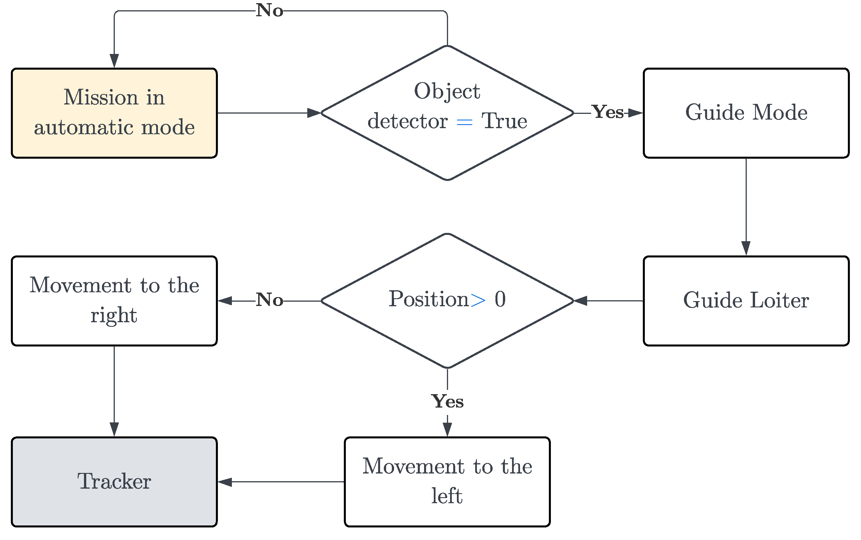
Figure 9 shows the control algorithm that describes the operation of the obstacle avoidance system. It shows that once the obstacle leaves the camera’s field of view, the drone resumes its mission in automatic mode and will remain in that mode if the presence of an obstacle is not detected.
4. Results and Discussion
The following are the results for the auxiliary systems supporting landing maneuvers and obstacle avoidance. These systems were implemented on a multirotor UAV in a controlled environment to evaluate the performance of both algorithms.
4.1. Test of Autonomous Landing
Considering the importance of developing autonomous systems that assist UAV landings in applications such as remote monitoring, where ensuring the integrity of the aircraft is vital to avoid material and data losses, the following are the results of the evaluation of the proposed autonomous landing.
Two scenarios were tested, when the heliport was detected and when it was not. These tests correspond to the execution of the landing guidance algorithm where a safe altitude of 4 [m] is established as sufficient to detect the heliport in the computer vision system, the area covered by the test zone process is 4 [m2], the standard deviation of the data obtained during the maneuver must be less than or equal to 16 [cm], and a lower speed limit of 20 [cm/s] is considered for the controlled landing.
Figure 10 shows the altitude registered by Pixhawk’s IMUs and LIDAR sensor during the maneuvers. There is a recurrent position error in Pixhawk. Table 3 summarizes the position errors in the tests corresponding to the first phase of the algorithm. The altitude_imu recorded data shows the most significant errors, with the highest error being 60.83% in test 1, while the lowest error is from LIDAR Lite v3 at 3.52% in test 3. This highlights the low precision of GPS and IMU in estimating position coordinates at smaller scales; the value recorded by Pixhawk (altitude_imu) is the most accurate estimate that the controller can calculate based on these sensors. Regarding the algorithm’s accuracy in correcting safe altitude, distance sensor measurements are considered for comparison with the reference. The errors upon reaching the final position do not exceed 8%, which is acceptable and does not affect subsequent processes.
In the context of remote monitoring applications, ensuring precise altitude control is crucial to prevent abrupt landings. During vertical descent maneuvers such as landing, especially, it is not advisable to propagate GPS position errors as they can affect the smoothness of the final descent curve. In this study, the implementation of a LIDAR sensor proves to be an effective solution for verifying altitude during landing, surpassing the limitations of Pixhawk measurements.
After completing the first stage (safe altitude), the Figure 11 shows the xy trajectory made by the quadcopter. In Figure 11(left), when the heliport was detected, the trajectory to center with the optical axis is unpredictable because it depends on where the heliport was detected and how long the tracking lasted. And, in Figure 11(right) when there was no heliport, the trajectory is irregular but corresponds to that defined by the test zone process; here, it is shown that the ground covered was 4 [m2]. The quadcopter’s characteristic is a vertical takeoff and landing (VTOL). For this reason, it is necessary to verify if landing in unknown terrain is safe before doing so. The detection of a heliport represents the successful completion of the flight mission, as it will land where it was programmed. However, in the case of possible loss of signal or direction, the accuracy of the distance sensor is crucial. Although the measurement is punctual, the continuous measurement can help successfully cover the landing zone.
Finally, after the quadcopter recognizes where landing is safe, the controlled landing process is executed. Figure 12 shows the variation in the z-velocity from the beginning of the controlled landing to the end of the maneuver. Initially, there is a pronounced transient phase, as it should be noted that prior to descent, the UAV is suspended in the air at a constant altitude. Then, there is a progressive decrease in velocity until it stabilizes at 20 [cm/s]. This value was set after observing that at lower speeds, the UAV tends to delay the landing significantly or remain static at a low altitude. The progressive decrease in speed is crucial to prevent the UAV from bouncing off the ground, particularly when the terrain is uneven, such as in volcanic environments. This precaution becomes even more significant when fragile devices form part of the payload. Additionally, incorporating a distance sensor to supplement GPS mitigates position errors that GPS alone may present, which is especially important in terrain with variable altitude.
The results presented by the autonomous landing system in the two most common scenarios are satisfactory; a successful landing was achieved in 90% of the tests, attributing the remaining 10% of issues to the difficulty of optimizing energy and processing capacity. In these exceptional cases, the UAV became disoriented due to the delay in image processing during the helipad tracking. Furthermore, by meeting the payload and energy consumption requirements, the prototype opens up the possibility of being applied in remote monitoring applications such as volcanic areas, where the terrain undergoes continuous variations. This adds an important capability for UAV safety and pilot confidence.
4.2. Obstacle Avoidance
Taking into account the flight conditions required for monitoring missions in remote areas, a self-sufficient system that enables obstacle avoidance is crucial to prevent accidents. The following are the results of the evaluation of the developed obstacle avoidance system. To do this, a square sponge measuring 1 × 1 [m2] is used to simulate a potential obstacle present in the aircraft’s flight path during monitoring.
4.2.1. Obstacle Detector Testing
Testing the operation of the designed obstacle detector and the reliability of the flight mode change, the UAV’s flight is manually initiated and it approaches an obstacle in its environment. When the distance sensor detects an object within 4 [m], the camera turns on to detect the obstacle, and the flight mode switches to guided mode. At this point, the UAV performs guided loitering, as described in Section 2.3.2 of this document.
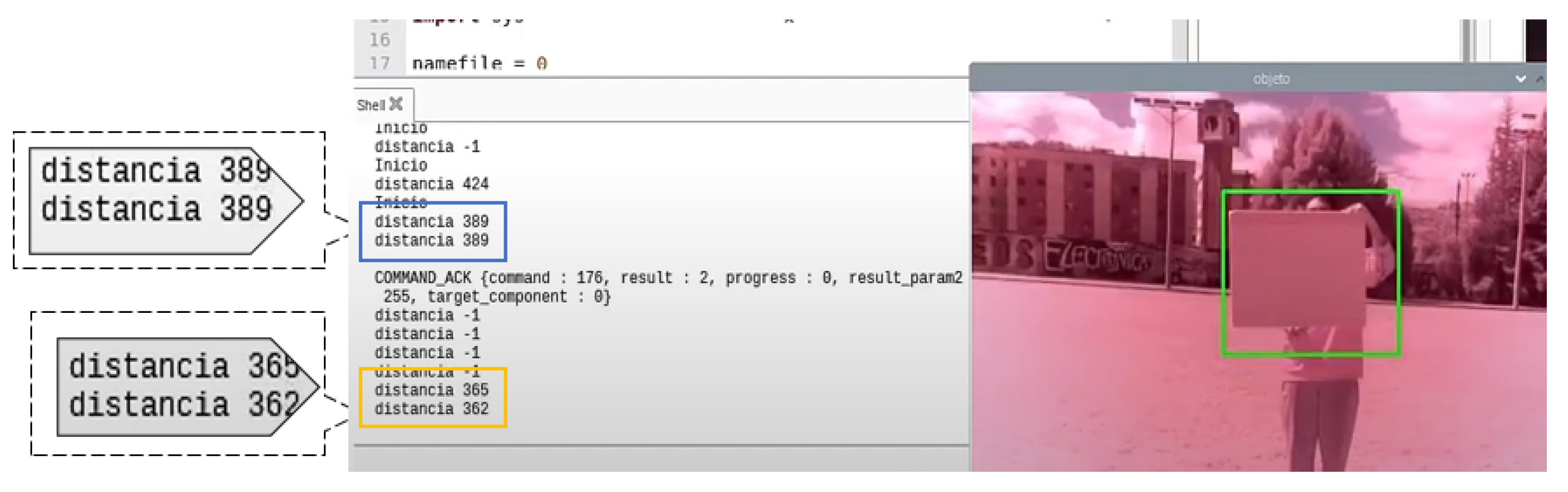
Figure 13 shows the results obtained by the obstacle detector, where one can see in a blue box the value of the distance at which the object is detected, and in yellow the value of the distance at which the UAV stops.
Furthermore, to confirm that the change of modes was performed correctly and that the position was maintained while the guided mode was set, the following is a graph obtained from the data stored by the Raspberry Pi.
Figure 14a illustrates the variation of the drone’s position over time. It can be observed that the drone starts by maintaining its position and then moves forward until it detects an obstacle at t = 16. Once the obstacle is detected, the drone stops and waits for further instructions. The same maneuver can be observed from a different perspective in Figure 14b.
The implemented system demonstrates a highly effective response time, with an error margin of approximately 0.3 [m], as analyzed in Table 4. This error value is considered completely acceptable, since the detection threshold used in the development of the tests is 4 [m], allowing the drone to perform evasive maneuvers with a wide margin of safety and assured success. These results demonstrate that the implemented obstacle detection system ensures that the drone can perform critical missions, such as volcano monitoring, without being damaged by collisions with obstacles in its environment. This increases the success rate of critical missions and confidence in the technology implemented.
4.2.2. Results of the Auxiliary Obstacle Avoidance System
Once the operation of the obstacle detector has been verified, the detector is tested together with the evader, i.e., the complete prototype. Achieving an optimal avoidance maneuver, it is essential to consider the trajectory that will give the drone the most flight autonomy while avoiding the obstacle. In this way, the aircraft will perform the avoidance maneuver with minimal energy expenditure, a critical factor in any drone mission [45].
One of the objectives of the avoidance system is to be completely autonomous during the execution of the mission preprogrammed in the mission planner, since the flight will be performed beyond the point of view. For this reason, the flight mode will always remain automatic, and only when an object is detected at less than 3 [m] will the flight mode change from automatic to guided. The drone will then perform a guided loiter, moving to the right or left as described in the previous section, until the object leaves the camera’s field of view. Once this is complete, the drone will resume the flight mission until it finishes or detects another obstacle that may cause a collision.
Considering what was described in the previous paragraph, the planned mission is started, which arms the drone engines, by code, and then starts the mission. In this part, it was necessary to implement a 4 [s] waiting time between the assembly of the drone’s motors and the start of the mission, so that the motors have enough time to reach the speed they need to stabilize. It is crucial to keep this in mind because if it is not executed, the drone will lose stability and orientation during startup.
From the data obtained by the Raspberry Pi during the flight, a 3D graph of the drone’s trajectory during the mission was generated. This graph is displayed in Figure 15 in Cartesian coordinates.
Finally, the response speed of the implemented auxiliary obstacle avoidance system is analyzed. For this purpose, the CSV file obtained by the Raspberry Pi is used, where the distance value measured by the LIDAR Lite v3 is recorded.
When analyzing the data presented in Table 5, it can be observed that the implementation of the tracker has increased the drone’s response time, resulting in a maximum error of approximately 1.1 [m]. Therefore, to ensure the proper functioning of this prototype, it is recommended to set the minimum detection threshold to a value greater than 2 [m] and to limit the flight speed to not exceed 10 [m/s], as a higher flight speed will lead to an increase in this error.
Thus, it can be affirmed that the implemented auxiliary system offers a satisfactory response time for the development of critical missions in a wide range of applications. Additionally, this system has been designed to work with low computational cost components, which translates into a significant economic advantage over existing alternatives in the market. In summary, the implemented system offers a cost-effective and highly effective solution for monitoring missions, aerial photography, and wildlife surveillance, among other applications.
5. Conclusions
The results demonstrate the effectiveness of using auxiliary platforms; the LOAS can be a good option for integration into monitoring missions commonly conducted beyond the pilot’s line of sight. Thanks to its low computational cost, this system allows aircraft to maintain their autonomy without significantly reducing flight time and enables safe operations even when performing tasks beyond the pilot’s visual range, which is crucial for accident prevention during flight. In this context, artificial vision technology supported by a distance sensor has proven to be effective in the tested environments and opens up the possibility for continuous improvement as science advances in enhancing processing capabilities with greater energy efficiency.
Artificial vision, thanks to the development of deep learning, provides increasingly better results in object detection. However, its implementation requires high processing power, which is not convenient for systems onboard UAVs. Nonetheless, a low-cost processing method to detect objects through artificial vision is the use of morphological operations, which can determine important characteristics of an object, such as color, edges, and shape, among others, and use them to separate it from the background and determine its position in the frame. The inclusion of low computational cost precisely limits the capabilities and operations of any equipment. In the case of UAVs, it is necessary to opt for this type of system because they also face very limited operating times. Therefore, addressing critical maneuvers such as obstacle avoidance and autonomous landing remains a challenge that seeks to find a balance between energy utilization and the effectiveness of auxiliary systems supporting these maneuvers.
6. Future Work
Once it is verified that the implemented system works efficiently, it is proposed to enhance the program by using a more powerful processing card that minimally impacts energy efficiency while enabling the visualization of the aircraft’s surroundings on a screen. Additionally, a camera with a wider focal aperture will be included, and presence sensors will be placed on the sides of the aircraft. This will enable the detection of objects on all sides of the UAV and determine the most effective route that the UAV should follow.
The developed landing system is intended to be used in multicopter-type aircraft focused on volcanic monitoring and agriculture. With this, it is expected that the drone will have a secure landing system that allows it to land on flat terrains, free from water or objects.
Author Contributions
Conceptualization, L.D.O. and E.S.L.; methodology, L.D.O. and E.S.L.; software, L.D.O. and E.S.L.; validation, L.D.O., E.S.L., H.P.L., P.J.C. and J.A.; formal analysis, L.D.O., E.S.L., H.P.L., P.J.C. and J.A.; investigation, L.D.O. and E.S.L.; resources, E.A.V.; data curation, L.D.O. and E.S.L.; writing—original draft preparation, L.D.O. and E.S.L.; writing—review and editing, P.J.C., H.P.L., J.A. and E.A.V.; visualization, L.D.O. and E.S.L.; supervision, P.J.C., J.A. and E.A.V.; project administration, P.J.C., J.A. and E.A.V.; funding acquisition, E.A.V. All authors have read and agreed to the published version of the manuscript.
Funding
This research was funded by Escuela Politecnica Nacional through the following grants: PIGR 21-01 and PIM 21-01.
Data Availability Statement
The results of the present work can be found in the online repositories, one for Autonomous Landing and other for Obstacle Avoidance, which gather all the necessary information to replicate the systems. The developed codes, the record of the tests conducted, and supplementary material providing in-depth descriptions of the work are available.
Acknowledgments
The authors gratefully acknowledge the financial support provided by Escuela Politécnica Nacional through the projects PIGR 21-01 and PIM 21-01.
Conflicts of Interest
The authors declare no conflict of interest.
Abbreviations
The following abbreviations are used in this manuscript:
| LOS | Line Of Sight |
| LOAS | Landing and Obstacle Avoidance System |
| BVLOS | Beyond Visual Line Of Sight |
| UAVs | Unmanned Aerial Vehicle |
| GPS | Global Positioning System |
| IMU | Inertial Measurement Unit |
| DNN | Deep Neural Network |
| VTOL | Vertical TakeOff and Landing |
| GV | Ground Vehicle |
| RNN | Recurrent Neural Network |
| DRL | Deep Reinforcement Learning |
| HMM | Hidden Markov Model |
References
- Melita, C.D.; Longo, D.; Muscato, G.; Giudice, G. Measurement and Exploration in Volcanic Environments. In Handbook of Unmanned Aerial Vehicles; Springer: Dordrecht, The Netherlands, 2014; pp. 2667–2692. [Google Scholar] [CrossRef]
- Jordan, B.R. Collecting field data in volcanic landscapes using small UAS (sUAS)/drones. J. Volcanol. Geotherm. Res. 2019, 385, 231–241. [Google Scholar] [CrossRef]
- Schroth, L. Drone Market Size 2020–2025; Technical Report; Drone Industry Insights: Hamburg, Germany, 2020. [Google Scholar]
- Campana, S. Drones in Archaeology. State-of-the-art and Future Perspectives. Archaeol. Prospect. 2017, 24, 275–296. [Google Scholar] [CrossRef]
- Niedzielski, T. Applications of Unmanned Aerial Vehicles in Geosciences: Introduction. Pure Appl. Geophys. 2018, 175, 3141–3144. [Google Scholar] [CrossRef]
- Moor, J.M.; Stix, J.; Avard, G.; Muller, C.; Corrales, E.; Diaz, J.A.; Alan, A.; Brenes, J.; Pacheco, J.; Aiuppa, A.; et al. Insights on Hydrothermal-Magmatic Interactions and Eruptive Processes at Poás Volcano (Costa Rica) From High-Frequency Gas Monitoring and Drone Measurements. Geophys. Res. Lett. 2019, 46, 1293–1302. [Google Scholar] [CrossRef]
- Cruzan, M.B.; Weinstein, B.G.; Grasty, M.R.; Kohrn, B.F.; Hendrickson, E.C.; Arredondo, T.M.; Thompson, P.G. Small Unmanned Aerial Vehicles (Micro-Uavs, Drones) in Plant Ecology. Appl. Plant Sci. 2016, 4, 1600041. [Google Scholar] [CrossRef]
- Marx, A.; McFarlane, D.; Alzahrani, A. UAV data for multi-temporal Landsat analysis of historic reforestation: A case study in Costa Rica. Int. J. Remote. Sens. 2017, 38, 2331–2348. [Google Scholar] [CrossRef]
- Granados-Bolaños, S.; Quesada-Román, A.; Alvarado, G.E. Low-cost UAV applications in dynamic tropical volcanic landforms. J. Volcanol. Geotherm. Res. 2021, 410, 107143. [Google Scholar] [CrossRef]
- Index for Risk Management for Latin America and The Caribbean. Technical Report. 2020. Available online: https://drmkc.jrc.ec.europa.eu/inform-index/Portals/0/InfoRM/2020/Subnational/LAC/LAC_INFORM_2020_v007_MainResults_Eng.pdf (accessed on 22 June 2023).
- Bi, Y.; Duan, H. Implementation of autonomous visual tracking and landing for a low-cost quadrotor. Optik-Int. J. Light Electron. Opt. 2013, 124, 3296–3300. [Google Scholar] [CrossRef]
- Lorenz, M. The History of Pixhawk—Auterion. 2008. Available online: https://auterion.com/the-history-of-pixhawk/ (accessed on 8 April 2023).
- Ghasri, M.; Maghrebi, M. Factors affecting unmanned aerial vehicles’ safety: A post-occurrence exploratory data analysis of drones’ accidents and incidents in Australia. Saf. Sci. 2021, 139, 105273. [Google Scholar] [CrossRef]
- ArduPilot. AERIALTRONICS Releases the New PENSAR. 2018. Available online: https://www.aerialtronics.com/2018/02/new-release-pensar (accessed on 27 July 2023).
- Guo, J.; Dong, X.; Gao, Y.; Li, D.; Tu, Z. Simultaneous Obstacles Avoidance and Robust Autonomous Landing of a UAV on a Moving Vehicle. Electronics 2022, 11, 3110. [Google Scholar] [CrossRef]
- Singla, A.; Padakandla, S.; Bhatnagar, S. Memory-Based Deep Reinforcement Learning for Obstacle Avoidance in UAV With Limited Environment Knowledge. IEEE Trans. Intell. Transp. Syst. 2021, 22, 107–118. [Google Scholar] [CrossRef]
- White, B.A.; Shin, H.S.; Tsourdos, A. UAV Obstacle Avoidance using Differential Geometry Concepts. IFAC Proc. Vol. 2011, 44, 6325–6330. [Google Scholar] [CrossRef]
- Lai, J.; Mejias, L.; Ford, J.J. Airborne vision-based collision-detection system. J. Field Robot. 2011, 28, 137–157. [Google Scholar] [CrossRef]
- Cocchioni, F.; Mancini, A.; Longhi, S. Autonomous navigation, landing and recharge of a quadrotor using artificial vision. In Proceedings of the 2014 International Conference on Unmanned Aircraft Systems (ICUAS), Orlando, FL, USA, 27–30 May 2014. [Google Scholar] [CrossRef]
- Stefano, G.D.; Romeo, G.; Mazzini, A.; Iarocci, A.; Hadi, S.; Pelphrey, S. The Lusi drone: A multidisciplinary tool to access extreme environments. Mar. Pet. Geol. 2018, 90, 26–37. [Google Scholar] [CrossRef]
- Schellenberg, B.J. Long Range UAS Operations for Volcanic Monitoring. Ph.D. Dissertation, University of Bristol, Bristol, UK, 2020. [Google Scholar]
- Everaerts, J. The use of unmanned aerial vehicles (UAVs) for remote sensing and mapping. Int. Arch. Photogramm. Remote. Sens. Spat. Inf. Sci. 2008, 37, 1187–1192. [Google Scholar]
- Flores, A.; Scipion, D.; Saito, C.; Apaza, J.; Milla, M. Unmanned Aircraft System for Andean Volcano monitoring and surveillance. In Proceedings of the 2019 IEEE International Symposium on Safety, Security, and Rescue Robotics (SSRR), Würzburg, Germany, 2–4 September 2019. [Google Scholar] [CrossRef]
- MAVLink Basics—Dev Documentation. Available online: https://ardupilot.org/dev/docs/mavlink-basics.html (accessed on 10 April 2023).
- Koubaa, A.; Allouch, A.; Alajlan, M.; Javed, Y.; Belghith, A.; Khalgui, M. Micro Air Vehicle Link (MAVlink) in a Nutshell: A Survey. IEEE Access 2019, 7, 87658–87680. [Google Scholar] [CrossRef]
- Flight Modes—Copter Documentation. Available online: https://ardupilot.org/copter/docs/flight-modes.html (accessed on 10 April 2023).
- Min, B.M.; Tahk, M.J.; Shim, H.C.D.; Bang, H.C. Guidance Law for Vision-Based Automatic Landing of UAV. Int. J. Aeronaut. Space Sci. 2007, 8, 46–53. [Google Scholar] [CrossRef]
- Gautam, A.; Sujit, P.; Saripalli, S. A survey of autonomous landing techniques for UAVs. In Proceedings of the 2014 International Conference on Unmanned Aircraft Systems (ICUAS), Orlando, FL, USA, 27–30 May 2014. [Google Scholar] [CrossRef]
- Cesetti, A.; Frontoni, E.; Mancini, A.; Zingaretti, P.; Longhi, S. A Vision-Based Guidance System for UAV Navigation and Safe Landing using Natural Landmarks. J. Intell. Robot. Syst. 2009, 57, 233–257. [Google Scholar] [CrossRef]
- Layman, T.; Fields, T.; Yakimenko, O.A. Evaluation of Proportional Navigation for Multirotor Pursuit. In Proceedings of the AIAA Scitech 2021 Forum, Virtual, 11–15 and 19–21 January 2021; American Institute of Aeronautics and Astronautics: Reston, VA, USA, 2021. [Google Scholar] [CrossRef]
- East, D. Missile Guidance and Pursuit: Kinematics, Dynamics and Control, N.A. Shneydor, Horwood Publishing, Coll House, Westergate, Chichester, West Sussex PO20 6QL, UK. 1998. 259pp. Illustrated. £30. Aeronaut. J. 1998, 102, 406. [Google Scholar] [CrossRef]
- Mcfadyen, A.; Mejias, L. A survey of autonomous vision-based See and Avoid for Unmanned Aircraft Systems. Prog. Aerosp. Sci. 2016, 80, 1–17. [Google Scholar] [CrossRef]
- Haralick, R.M.; Sternberg, S.R.; Zhuang, X. Image Analysis Using Mathematical Morphology. IEEE Trans. Pattern Anal. Mach. Intell. 1987, PAMI-9, 532–550. [Google Scholar] [CrossRef] [PubMed]
- Israelsen, J.; Beall, M.; Bareiss, D.; Stuart, D.; Keeney, E.; van den Berg, J. Automatic collision avoidance for manually tele-operated unmanned aerial vehicles. In Proceedings of the 2014 IEEE International Conference on Robotics and Automation (ICRA), Hong Kong, China, 31 May–7 June 2014. [Google Scholar] [CrossRef]
- Getreuer, P. A Survey of Gaussian Convolution Algorithms. Image Process. Line 2013, 3, 286–310. [Google Scholar] [CrossRef]
- Sharda, A. Image Filters: Gaussian Blur. 2021. Available online: https://aryamansharda.medium.com/image-filters-gaussian-blur-eb36db6781b1 (accessed on 4 August 2023).
- Prashanth, C.R.; Sagar, T.; Bhat, N.; Naveen, D.; Rupanagudi, S.R.; Kumar, R.A. Obstacle detection & elimination of shadows for an image processing based automated vehicle. In Proceedings of the 2013 International Conference on Advances in Computing, Communications and Informatics (ICACCI), Mysore, India, 22–25 August 2013. [Google Scholar] [CrossRef]
- Li, S.A.; Chou, L.H.; Chang, T.H.; Yang, C.H.; Chang, Y.C. Obstacle Avoidance of Mobile Robot Based on HyperOmni Vision. Sens. Mater. 2019, 31, 1021. [Google Scholar] [CrossRef]
- McIlhagga, W. The Canny Edge Detector Revisited. Int. J. Comput. Vis. 2010, 91, 251–261. [Google Scholar] [CrossRef]
- OpenCV:Canny Edge Detection. Available online: https://docs.opencv.org/3.4/da/d22/tutorial_py_canny.html (accessed on 4 August 2023).
- Raghava, N.; Gupta, K.; Kedia, I.; Goyal, A. An Experimental Comparison of Different Object Tracking Algorithms. In Proceedings of the 2020 International Conference on Communication and Signal Processing (ICCSP), Melmaruvathur, India, 28–30 July 2020. [Google Scholar] [CrossRef]
- Park, J.W.; Kim, S.; Lee, Y.; Joe, I. Improvement of the KCF Tracking Algorithm through Object Detection. Int. J. Eng. Technol. 2018, 7, 11. [Google Scholar] [CrossRef]
- Bupe, P.; Haddad, R.; Rios-Gutierrez, F. Relief and emergency communication network based on an autonomous decentralized UAV clustering network. In Proceedings of the SoutheastCon, Fort Lauderdale, FL, USA, 9–12 April 2015. [Google Scholar] [CrossRef]
- ArduPilot. GitHub—ArduPilot/Pymavlink: Python MAVLink Interface and Utilities. 2016. Available online: https://github.com/ArduPilot/pymavlink (accessed on 1 May 2023).
- Lee, J. Optimization of a modular drone delivery system. In Proceedings of the 2017 Annual IEEE International Systems Conference (SysCon), Montreal, QC, Canada, 24–27 April 2017. [Google Scholar] [CrossRef]
Figure 1.
Proportional guidance geometry.

Figure 2.
Pursuit guidance geometry.

Figure 3.
Evasion maneuvers by changing the flight mode.

Figure 4.
Connection diagram.

Figure 5.
Guided landing algorithm.

Figure 6.
Structure of the object detection stage.

Figure 7.
(a) Image in the HSV system. (b) Result of the color detector. (c) Result of the canny edge detector. (d) Edge dilatation. (e) Final result of the obstacle detector.
Figure 7.
(a) Image in the HSV system. (b) Result of the color detector. (c) Result of the canny edge detector. (d) Edge dilatation. (e) Final result of the obstacle detector.

Figure 8.
Flow diagram of tracker operation.

Figure 9.
Obstacle avoidance system diagram.

Figure 10.
Altitude record without helipad detected (left) and with helipad detected (right).

Figure 11.
X vs. Y trajectory without helipad detected (left) and with helipad detected (right).

Figure 12.
Vz during last stage of landing.

Figure 13.
Obstacle detector result.

Figure 14.
(a) Position vs. Time, (b) Position X vs. Position Y.

Figure 15.
Flight path obtained from the data in the CSV file.


Table 1.
Most common MAVLink commands.
| Command | ID | Description |
|---|---|---|
| TAKEOFF | 22 | Launches the UAV to a specified altitude. |
| LAND | 21 | Landing the UAV. |
| ARM-DISARM | 400 | Arms or disarms the motors. |
| EXTENDED_SYS_STATE | 245 | Allows presenting or using the flight state values of the drone. |
| MAV_FRAME_BODY | 8 | Allows controlling the movement of the vehicle based on its position. |
Table 2.
Principal flight modes.
| Modes | Description |
|---|---|
| AltHold | Maintains altitude with safe roll and pitch levels |
| Auto | This is the general mode with which the drone starts the flight, once the order to start the mission has been sent. While the automatic mode is active, no flight characteristics previously set in the preprogrammed mission can be modified |
| Guided | This mode allows real-time control of the mission, i.e., while in this flight mode, orders can be given to the drone without having been previously programmed |
| Loiter | As its name indicates, this mode allowsnthe UAV to keep flying in the same position despite the wind |
| RTL | Return to the takeoff point and land |
| Stabilize | This flight mode ensures safe levels of roll and pitch |
Table 3.
Relative errors between the onboard logging of the prototype and the GPS data.
| No. Test | Initial Altitude | Final Altitude | ||
|---|---|---|---|---|
| Altitude_imu | LIDAR Lite v3 | Altitude_imu | LIDAR Lite v3 | |
| 1 | 4.33% | 4.33% | 48.23% | 4.71% |
| 2 | 8.68% | 7.89% | 18.48% | 17.12% |
| 3 | 12.75% | 3.52% | 4.46% | 20.61% |
| 4 | 60.83% | 12.08% | 60.83% | 12.08% |
Table 4.
UAV response to the obstacle detector for a detection threshold of 4 [m] with a flight speed of 10 [m/s].
Table 4.
UAV response to the obstacle detector for a detection threshold of 4 [m] with a flight speed of 10 [m/s].
| Test Number | Detection Distance [m] | Detection Error [m] | UAV Stopping Distance [m] | UAV Stopping Error [m] |
|---|---|---|---|---|
| 1 | 3.89 | 0.11 | 3.65 | 0.35 |
| 2 | 3.96 | 0.04 | 3.92 | 0.08 |
| 3 | 3.40 | 0.6 | 3.61 | 0.39 |
Table 5.
UAV response speed once the prototype is implemented for a detection threshold of 3 [m] with a flight speed of 10 [m/s].
Table 5.
UAV response speed once the prototype is implemented for a detection threshold of 3 [m] with a flight speed of 10 [m/s].
| Test Number | Detection Error [m] | UAV Stopping Error [m] |
|---|---|---|
| 1 | 2.18 | 0.82 |
| 2 | 1.98 | 1.02 |
| 3 | 1.96 | 1.04 |
Disclaimer/Publisher’s Note: The statements, opinions and data contained in all publications are solely those of the individual author(s) and contributor(s) and not of MDPI and/or the editor(s). MDPI and/or the editor(s) disclaim responsibility for any injury to people or property resulting from any ideas, methods, instructions or products referred to in the content. |
© 2023 by the authors. Licensee MDPI, Basel, Switzerland. This article is an open access article distributed under the terms and conditions of the Creative Commons Attribution (CC BY) license (https://creativecommons.org/licenses/by/4.0/).
Share and Cite
MDPI and ACS Style
Ortega, L.D.; Loyaga, E.S.; Cruz, P.J.; Lema, H.P.; Abad, J.; Valencia, E.A. Low-Cost Computer-Vision-Based Embedded Systems for UAVs. Robotics 2023, 12, 145. https://doi.org/10.3390/robotics12060145
AMA Style
Ortega LD, Loyaga ES, Cruz PJ, Lema HP, Abad J, Valencia EA. Low-Cost Computer-Vision-Based Embedded Systems for UAVs. Robotics. 2023; 12(6):145. https://doi.org/10.3390/robotics12060145
Chicago/Turabian StyleOrtega, Luis D., Erick S. Loyaga, Patricio J. Cruz, Henry P. Lema, Jackeline Abad, and Esteban A. Valencia. 2023. "Low-Cost Computer-Vision-Based Embedded Systems for UAVs" Robotics 12, no. 6: 145. https://doi.org/10.3390/robotics12060145
Note that from the first issue of 2016, this journal uses article numbers instead of page numbers. See further details here.