
Virtual Reality Teleoperation System for Mobile Robot Manipulation


Faculty of Systems, Electronics and Industrial Engineering, Universidad Tecnica de Ambato (UTA), Ambato 180206, Ecuador
*
Author to whom correspondence should be addressed.
†
These authors contributed equally to this work.
Robotics 2023, 12(6), 163; https://doi.org/10.3390/robotics12060163
Submission received: 27 September 2023
/
Revised: 16 November 2023
/
Accepted: 24 November 2023
/
Published: 29 November 2023
(This article belongs to the Special Issue Digital Twin-Based Human–Robot Collaborative Systems)
Abstract
:Over the past few years, the industry has experienced significant growth, leading to what is now known as Industry 4.0. This advancement has been characterized by the automation of robots. Industries have embraced mobile robots to enhance efficiency in specific manufacturing tasks, aiming for optimal results and reducing human errors. Moreover, robots can perform tasks in areas inaccessible to humans, such as hard-to-reach zones or hazardous environments. However, the challenge lies in the lack of knowledge about the operation and proper use of the robot. This work presents the development of a teleoperation system using HTC Vive Pro 2 virtual reality goggles. This allows individuals to immerse themselves in a fully virtual environment to become familiar with the operation and control of the KUKA youBot robot. The virtual reality experience is created in Unity, and through this, robot movements are executed, followed by a connection to ROS (Robot Operating System). To prevent potential damage to the real robot, a simulation is conducted in Gazebo, facilitating the understanding of the robot’s operation.
1. Introduction
Virtual reality (VR) and mobile platforms have emerged as pivotal technologies in revolutionizing industrial applications, particularly in the realm of robotics. The integration of VR with robots offers an unprecedented level of human–robot interaction and control [1,2]. Through immersive VR environments, operators can remotely guide and monitor robotic systems with enhanced precision and efficiency [3]. This not only mitigates the physical constraints of traditional human–machine interfaces but also minimizes the need for on-site presence, thereby improving safety in hazardous industrial settings. The symbiotic relationship between VR and robots facilitates intricate tasks, such as manipulation of objects in complex environments, with an unparalleled level of dexterity and adaptability. This convergence of technologies has significant implications for industries ranging from manufacturing to logistics, where the seamless collaboration between human operators and robotic entities leads to heightened productivity and operational excellence [4].
Simultaneously, the incorporation of mobile platforms in robotics amplifies the flexibility and versatility of industrial automation. Mobile robots equipped with advanced sensors and intelligent algorithms can navigate dynamic environments autonomously, optimizing workflows and reducing human involvement [5,6,7]. These platforms are particularly adept at performing tasks in unstructured or changing environments, such as warehouses or assembly lines. The synergy between mobile platforms and robotics contributes to a more agile and responsive industrial ecosystem, capable of adapting to evolving demands [8,9]. Furthermore, the integration of mobile robotics enhances the scalability of automated processes, allowing for the swift reconfiguration of production lines and the efficient handling of diverse tasks. In the academic pursuit of advancing industrial automation, the fusion of virtual reality with robots and the strategic deployment of mobile platforms represent a transformative paradigm, offering novel solutions to challenges in contemporary manufacturing and logistics [10,11].
Robotics, as a field, aims to establish reliable relationships and effective interactions between humans and machines, seeking to fully harness the capabilities of advanced machines while empowering workers with new skills and innovative tools within the framework of Industry 4.0 technologies on a global scale [12]. While the ultimate goal of robotics is to achieve fully autonomous robots, practical applications of such systems remain limited. Consequently, there is a growing emphasis on advocating for remote-controlled robotics with human involvement to address these challenges [13]. These robots offer the advantage of executing tasks without the need for physical presence, ensuring the health and safety of human operators, particularly in inaccessible areas [14].
In the pursuit of advancing Industry 4.0, virtual reality (VR) has emerged as a transformative tool within the realm of robotics. Defined as a medium of human–technological interaction that facilitates the creation and simulation of complex scenarios, VR holds significant potential for robot training [15,16]. Beyond training, VR applications extend to various sectors, enhancing internal operations in settings such as operating rooms and hospitals, exemplified by the HoloSurg system developed by Exovite [17]. Furthermore, VR’s reach expands into non-industrial domains, such as the Thyssen-Bornemisza Museum, where visitors can explore visual representations of paintings in a realistic virtual environment [18].
The efficacy of enabling humans to control robots remotely hinges on the development of a robust human–robot interface. This interface is essential for providing operators with heightened situational awareness and intuitive control mechanisms that do not impose an additional cognitive load, forming the foundation for intelligent decision-making [19]. In collaborative environments between humans and robots, an intuitive control system translates to more efficient task execution and safer performance [20]. Notably, in the context of industrial robot control interfaces, there exists a noticeable gap that limits human operators’ perception of the situation [21]. Current solutions, relying on visual feedback like camera feeds, pose challenges in spatial comprehension, including the assessment of distances between robots and obstacles [22].
Human–robot interfaces have increasingly focused on visually recreating scenarios and transferring image data into an immersive environment for remote robot control [23]. Techniques such as depth-sensing RGB cameras, LiDAR, and photogrammetry have been evaluated to generate three-dimensional models of the scene, with virtual reality serving as an immersive and intuitive user interface that provides a sense of presence [24]. In this context, our work contributes by developing a virtual reality interface using Unity and HTC Vive Pro 2 goggles, allowing individuals to immerse themselves in a virtual world to learn about the operation and control of the KUKA youBot manipulator. The communication is facilitated through the ROS TCP Connector, enabling data transfer from Unity to ROS.
This paper unfolds several critical highlights at the intersection of virtual reality and robotics in industrial applications.
- Advancements in human–robot interaction: the paper emphasizes the significance of effective human–robot interfaces, crucial for remote robot control. It stresses the need for interfaces that provide operators with heightened situational awareness and intuitive control mechanisms, promoting efficient task execution and enhanced safety.
- Transformative role of virtual reality (VR): virtual reality is identified as a transformative tool, particularly in the training of robots. By creating and simulating complex scenarios, VR proves instrumental in providing a realistic and immersive environment for learning about the operation and control of robotic systems.
- Addressing limitations in current control interfaces: the research addresses the existing gap in industrial robot control interfaces, highlighting limitations associated with conventional visual feedback solutions like camera feeds. It advocates for the use of VR as an intuitive and immersive user interface, offering a solution to challenges in spatial comprehension and perception in remote robot control scenarios.
This article is structured as follows: Section 2 presents different works related to the subject of study. Section 3 explores the kinematic model of the KUKA youBot, examining both the omnidirectional platform and robotic arm through detailed equations and the Denavit–Hartenberg method. Section 4 shows how the simulation of the robot is developed in Gazebo software 11.0.0. The creation of a virtual reality environment within Unity represents a pivotal component of this study, facilitating the seamless interaction between the physical world and the digital realm sowed in Section 5. The results of the platform are shown in Section 6. Finally, Section 7 details the conclusions and future work.
2. State of the Art
In this section, a set of related works is presented concerning the application of virtual reality technologies and the use of robots.
In the article by Peppoloni et al. [25], they highlight the development of an augmented reality control interface using the CoCo framework. This interface enables the teleoperation of a robot through gestures and hand movements, making user interaction with the virtual environment more accessible. Visual feedback is obtained through Kinect sensors and an HMD (Head-Mounted Display), and communication with the robot is achieved through ROS (Robot Operating System) and the Leap ROS interface. This proposal focuses on gesture-based and visual interaction for robot control. Carlos A. García et al. [26] present an augmented reality interface for controlling a Scorbot ER 4U. In this work, kinematic analysis is conducted to define the robot’s control method. A Raspberry Pi card is used for control, utilizing the MQTT protocol to ensure security and message transmission quality from the virtual environment to the controller.
Caiza et al. [27] focus on a teleoperation system for robots in the oil and gas industry, where tasks such as equipment maintenance or inspection are challenging due to the remote and harsh environments. This project is applied in Petroamazonas EP to enable remote maintenance and pipeline inspection by operators. The virtual reality environment is developed in Unity, utilizing a Leap Motion sensor to detect motion commands, including both arm position and speed for the robotic arm. In Botev [28], the development of an immersive virtual reality interface for manipulating the Turtlebot 2 robot is emphasized. The Turtlebot 2 operates on the ROS Kinetic operating system. Before testing the robot, a simulation is conducted in Gazebo 7, allowing for an understanding of its operation and analysis of its behavior in different situations. Communication between ROS and the Unity virtual environment is established using the TCP-IP protocol, with the aid of a package known as ROS Rosbridge and the RosSharp library in Unity. Additionally, an Extended Reality (XR) plugin is employed to quickly create the virtual reality scenario.
On the other hand, in Rakita et al. [29], the research focuses on the effects of delays in the teleoperation interface of an imitation-control robot. Teleoperation involves a user moving their arms to directly guide the robot. The study includes an experiment with human subjects that reveals how different types and amounts of delays impact task performance. Movements under different delay conditions are compared to identify strategies operators employ to adapt to these conditions and explain performance differences. In Kim Eishi et al. [30], a study examines the impact of communication latency on teleoperation performance and the mental workload of operators in remote environments. Two tasks are conducted with a group of participants to assess the effects of different levels of communication latency: a duration reproduction task and a maze navigation task. The results revealed that an increase in communication latency resulted in a significant deterioration in performance. Additionally, participants reported a decrease in their self-assessment of their performance and an increase in frustration, effort, and mental demands as latency increased.
The study by di Lanzo et al. [31] presents the creation and use of virtual reality learning objects in the fields of robotics, mechanics, and electronics. They employed two virtual reality approaches, one for mobile devices and another immersive one with Oculus Rift. They developed 3D objects for robotics and mechanics, accessible on both mobile devices and laptops through the “Virtual Bullet Time” application. For electronics, they created an Immersive Virtual Laboratory using Oculus Rift and Leap Motion. Preliminary results indicate that this technology enhances the learning process for students. In Pañe-Tapia et al. [32], they designed a virtual reality control interface to manipulate the Kinova Jaco robot using HTC Vive virtual reality goggles. This interface allows the user to monitor the robotic arm, obtain information on joint states, locate the end-effector’s position, and control it. For arm movement planning, they employ the Open Motion Planning Library, an open-source library with planning algorithms. Additionally, they use MoveIt for kinematic analysis and collision checking between various objects.
In summary, these research studies demonstrate a growing interest in the use of virtual reality in education, particularly in the fields of robotics, mechanics, and electronics. Virtual reality learning objects have been developed for both mobile devices and immersive headsets, enhancing students’ understanding and learning experiences in these areas. Additionally, the importance of addressing communication latency in robotic teleoperation environments is emphasized. Latency can have a negative impact on operator performance and increase their mental workload.
3. KUKA youBot Kinematic Model
This section explores the kinematic model of the KUKA youBot, focusing on both the omnidirectional platform and the robotic arm. The omnidirectional platform, equipped with mecanum wheels, is analyzed for unrestricted movement, with a detailed description provided through equations and geometric dimensions. The robotic arm’s kinematics are elucidated using the Denavit–Hartenberg method, presenting DH parameters and reference frames for each link. The comprehensive Gazebo application developed simplifies DH parameter calculations by allowing dynamic adjustments to link positions through a graphical interface.
3.1. Omnidirectional Platform Kinematics
The platform is comprised of mecanum omnidirectional wheels, which enable unrestricted movement in any direction without the front of the platform rotating. To have an appropriate kinematic model, it is essential to consider the arrangement of the rollers on the wheels [33].
According to the research of [27,34], the kinematics of the platform are described by Equations (1)–(3) and its parameters are shown in Figure 1. In this context, and denote the velocities along the X and Y axes, respectively, while represents the angular velocity of the platform. The term refers to the individual linear velocity of each wheel. Consequently, motion in the plane is determined through linear combinations of the wheel velocities.
On the other hand, Figure 2 shows the parameters and that are mentioned in Equations (2) and (3), respectively, which are related to the angle of the wheel rollers. The translational and rotational movements are represented in Figure 2 by a shaded platform. This indicates the direction in which it will move based on the linear velocities.
3.2. Kinematics of the Robotic Arm
For the analysis of robotic manipulators, it is more practical to assign reference frames to each link to form a kinematic chain [27,35]. The fundamental method for assigning reference frames is the Denavit–Hartenberg (DH) method, which describes the robot in terms of the static parameters of the links and the variables of each joint. This method is based on forward kinematics, which uses homogeneous transformation matrices to calculate the position and orientation data of the robotic arm’s end-effector. This matrix consists of a translation part that indicates the end-effector’s position and a rotation matrix that determines the end-effector’s orientation through the calculation of Euler angles, obtained using inverse trigonometric functions. The measurements of each link required for DH parameter calculation, as well as the rotational limits, are presented in Figure 3.
Figure 4 illustrates the positioning of the reference frames for each joint, which are assigned at the end of each link, specifically at the joint connecting to the previous link. The first reference frame is typically assigned to the base of the robot, and it remains as a fixed coordinate system acting as the global reference frame. The positions and orientations of all other parts of the robot are described in relation to this initial frame. In other words, all the other reference frames are established with respect to the base reference frame. Table 1 presents the Denavit–Hartenberg parameters, which are used to get the five homogeneous transformation matrices for each link [36].
With the 4 DH parameters calculated, they are substituted into Equation (4) to obtain the matrices for each link, where the parameters S and C correspond to the sine and cosine functions, respectively [36].
Finally, to get the overall transformation matrix, you multiply all the matrices for each link, as shown in Equation (5).
3.3. Gazebo Application for Simplified DH Parameter Calculation in Robotic Arm Kinematics
The method for calculating the various DH parameters can be an extensive and somewhat complicated procedure. To avoid this, a Gazebo application is developed, allowing you to change the positions of each of the links through a graphical interface. Based on these positions, the total transformation matrix is calculated, which is necessary to determine the position and orientation of the robotic arm’s end-effector.
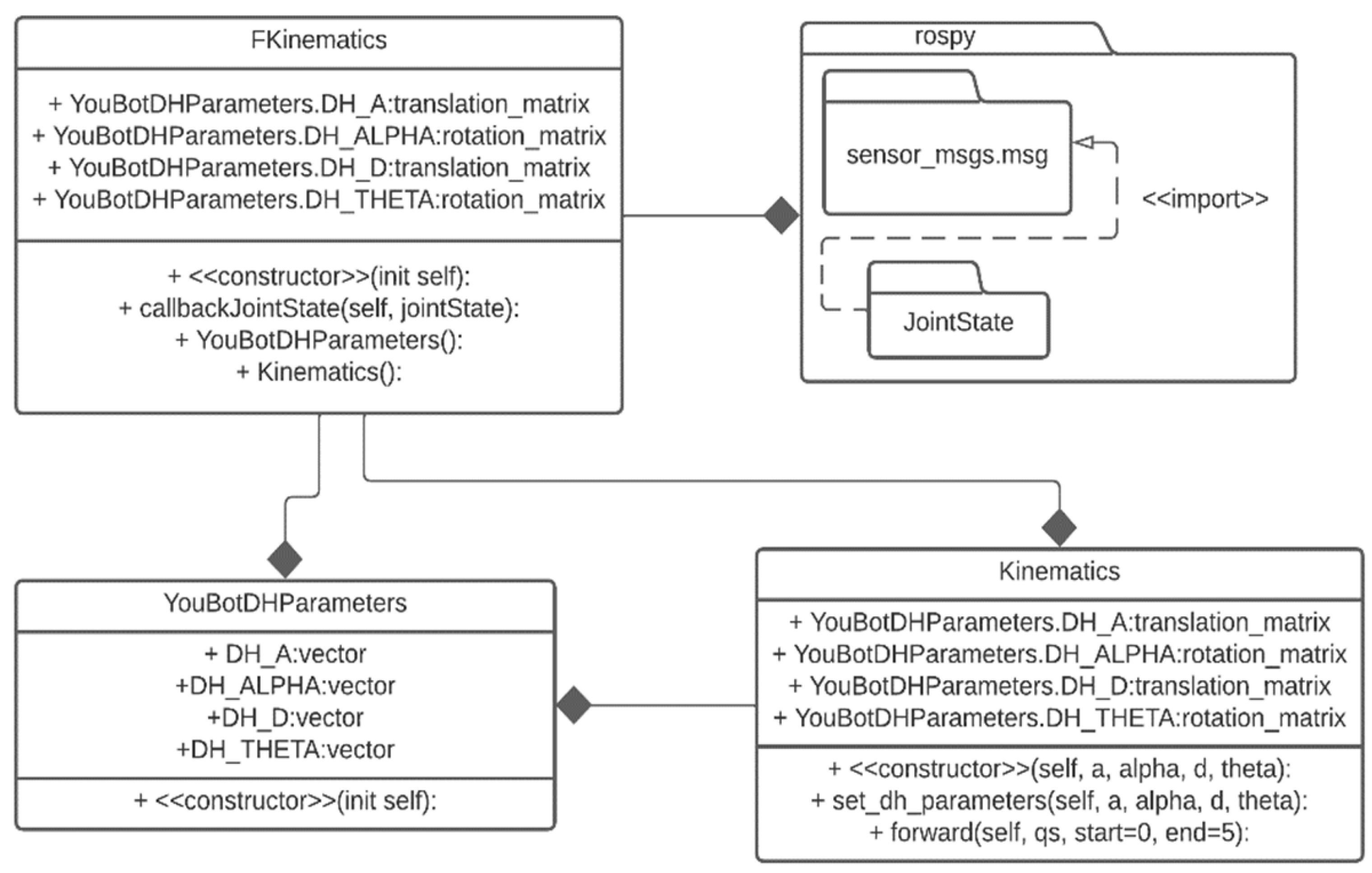
Figure 5 shows the class diagram for the Python application. It consists of two classes that depend on the main class, meaning this class has a composition relationship that predominates over the others. This class depends on the rospy package, which is required for working with ROS dependencies. It defines attributes for the DH parameters needed to calculate the position and orientation of the robotic arm’s end-effector, which are of type translation and rotation. The secondary class, “YouBotDHParameters”, consists of a single constructor method for initializing the class. It has DH attributes of type vector, as these values are entered in this format before being converted into matrices.
The “kinematics” class is responsible for calculating the homogeneous transformation matrices for each link of the arm, based on the positions of the links and the provided 4 DH parameters. The translation matrix describes the displacement of a part of the robot from one point to another in three-dimensional space and is used to determine its new position when multiplied by the coordinate vector of a point. On the other hand, the rotation matrix is used to represent the orientation of a specific part of the robot in three-dimensional space.
Figure 6 displays the graphical interface where the positions of the links are presented, and you can change these values. It is important to note that the parameters for forward kinematics calculate the position and orientation of the robotic arm’s end-effector based on a reference system, which would be the platform. It also depends on the positions of the links. In other words, if the positions change, the position and orientation of the end-effector will also change.
Equation (6) presents the result of the total transformation matrix obtained through the application. It extracts two key components: the translation matrix for the end-effector’s position and the 3 × 3 rotation matrix to define the end-effector’s orientation. Table 2 provides the corresponding values for the position and orientation of the end-effector, expressed in meters and radians, respectively. These data are essential for trajectory planning and robotic arm control, as they enable precise movements to specific locations and are used by algorithms to calculate the sequence of movements required to reach the desired goal.
4. Managing Robotic Arm and Mobile Platform Movement in Gazebo
In this section, we embark on a comprehensive exploration of control systems governing two vital aspects of our robotic system: the manipulator arm and the mobile platform. Effective control of the robotic arm is a foundational component of its functionality, involving precise positioning and movement. The accompanying class diagrams and control mechanisms presented provide insight into how the robotic arm’s various joints are manipulated and protected. Simultaneously, we delve into the intricate control of the mobile platform, known for its omnidirectional capabilities and unique modes of movement. This section encompasses the integrated control strategies for both these essential components, shedding light on the technology that powers their operation within a dynamic environment.
4.1. Manipulator Arm Control
Figure 7 shows the class diagram for arm control, where there are two classes that depend on the main class “arm_position”. This main class contains attributes for each link, and they are visible to all elements of the class. In the secondary class “my_publisher”, the node is initialized, along with the topic where the positions of the links will be published, as well as acceleration, velocity, and effort values. Additionally, it controls the lower and upper rotational limits of each link, as presented in Table 3, to prevent any damage to the robot’s motors. The “main” class is responsible for calling the main class to execute the received position data. The main class depends on the rospy package and uses the following libraries for arm control:
- JointTrajectory: provides a message structure for representing joint motion trajectories of the robot, and it also includes information such as the trajectory’s start time, duration, and a list of trajectory points.
- JointTrajectoryPoint: allows storing information about a specific joint position in a motion trajectory. It contains data regarding the positions, velocities, accelerations, and efforts of the joints at a particular point in the trajectory.
- std_msgs.msg: provides standard messages for data exchange, meaning it allows standardized communication with other nodes in the ROS system [37].
Figure 8 shows the movement of the arm according to the set positions. Initially, the arm is in the resting state or initial position, and once the node responsible for sending the data is executed, the Gazebo node starts receiving position data for arm movement. The topic through which data are published and subscribed is of type “JointTrajectory”, which provides the data structure for representing joint motion trajectories.
4.2. Mobile Platform Control
It is important to consider that the mobile platform is omnidirectional thanks to its Mecanum wheels, which provide two different modes of movement. Firstly, there is rotational or angular movement, where the platform rotates as a whole with the front part. Secondly, there is linear movement, which allows the platform to move left or right without the need for the front part to rotate. In Figure 9, the class diagram is presented, in which we find a single main class that contains multiple float-type attributes. Additionally, this main class establishes a composition relationship with the rospy package. Furthermore, this rospy package contains the Twist library, which enables the expression of platform velocity in terms of linear and angular velocity. Below is the description of each method used within the main class:
- Constructor: this method is used to initialize the main class. Here, the node to be created and the topic (cmd_vel) in which linear and angular wheel speeds will be published are defined. Additionally, a time interval is set for each message sent, and a while loop is implemented to continuously send velocity data.
- Shutdown: this method is used to stop the movement of the mobile platform. In other words, once the script is executed, the platform starts moving and continues moving until the user decides to stop it through an action in the console. To achieve this, a function is created that sends a signal to the robot to stop.
- Main: this function calls the main class to start and stop the application, and also displays a message in the console indicating that the robot has been stopped.
Figure 10 shows the forward and backward movement of the platform using the ‘geometry_msgs.msg’ library with the Twist module. This includes three components (x, y, z) representing linear velocities. To move forward, a positive value is assigned to the ‘x’ component, while a negative value is assigned to move backward. Lateral movement to the left or right is achieved by simply adjusting the linear velocity in the ‘y’ component. To move to the right, a negative value is set, and to the left, a positive value. Regarding rotational movement, the Twist library is also used. In this case, rotational movement in the (x, y) components is not applicable, as the platform cannot perform that type of movement. Therefore, only a value is assigned to the ‘z’ component. The direction of rotation depends on the positive or negative sign assigned to this component.
Additionally, the velocity and acceleration of the platform are also taken into account, as they are two crucial parameters in robot operation, and their careful consideration is essential to ensure efficiency and safety. The KUKA youBot has a speed limit of 0.8 m/s and an acceleration of 0.5 m/s, which allows for smooth and controlled motion, minimizing the risk of abrupt movements, vibrations, and detrimental collisions. Time is a factor that depends directly on whether a constant acceleration is considered in the robot’s movement, and with the right combination of time and acceleration, damage can be avoided when transporting objects.
5. Virtual Reality Environment in Unity
The creation of a virtual reality environment within Unity represents a pivotal component of this study, facilitating the seamless interaction between the physical world and the digital realm. This section delves into the intricacies of this virtual realm and is further divided into two critical subdomains. The first subsection details the techniques and methodologies employed for motion tracking within Unity, outlining the fundamental principles behind the precise measurement of physical object displacement in the virtual space. The second subsection explores the communication architecture implemented to ensure the real-time exchange of data between the HTC SteamVR Base Station 2.0 tracking system, the HTC VIVE Pro headsets, and Unity, allowing for synchronized and accurate immersion in the virtual environment. Together, these subsections elucidate the technical underpinnings that underlie the successful integration of physical and digital realities.
5.1. Implementation of KUKA youBot Tracking System
For robot position detection, Lighthouse-tracking technology is employed to achieve precise real-time tracking. Strategically placed Lighthouse base stations within the tracking area facilitate the accurate determination of the robot’s position. These base stations emit continuous infrared laser signals and synchronization pulses, effectively saturating the surrounding space. Equipped with photosensors, the robot KUKA youBot, HTC Vive Pro 2 headsets, and controllers capture these signals. The system operates based on the principles of temporal synchronization and the time it takes for a laser beam to reach a specific photosensor. As multiple base stations are involved in this process, precise triangulation is performed to calculate the exact 3D spatial position. This is achieved through the intersection of laser beams emitted by the base stations and detected by the robot’s photosensors. When multiple lines of sight intersect, the point of intersection in 3D space determines the precise robot position.
To carry out the displacement measurement of a KUKA youBot robot in a virtual reality environment using HTC SteamVR Base Station 2.0 and HTC VIVE Pro, a meticulous calibration process was implemented. This process consists of two main stages: the calibration of the SteamVR Base Stations and the calibration of the HTC VIVE Pro headsets. Calibration of the SteamVR Base Stations is performed to establish the necessary spatial reference for measurement. During this phase, the base stations are adjusted and positioned to ensure adequate coverage of the working area. Calibration of the HTC VIVE Pro headsets involves configuring the infrared cameras in the headsets to detect and track the reflective marker attached to the robot.
Once the calibration process has been completed, the KUKA youBot robot is placed in the virtual environment, and a reflective marker is attached to the robot. This marker, through its reflective surface, reflects the infrared light emitted by the SteamVR Base Stations. Both the base stations and the HTC VIVE Pro headsets use this information to track the position of the marker in real-time. The combination of these data enables accurate calculation of the robot’s displacement in the 3D space of the virtual environment.
HTC Vive Pro 2 Lighthouse base stations utilize two rapidly rotating laser emitters, operating at 60 revolutions per second, ensuring a high data sampling rate. Once the infrared laser position data are acquired, they are transmitted to the ROS (Robot Operating System) module. The Moon-wreckers framework is employed to publish the SteamVR location data on the ROS topic. The optical data acquisition frequency is limited to 60 Hz due to the laser rotation speed. However, to achieve faster updates, Unity’s SteamVR plugin complements this data with that from an Inertial Measurement Unit (IMU). The IMU operates at a significantly higher update frequency of 250 Hz, enhancing motion-tracking precision. The fusion of optical data from base stations with IMU data ensures an update frequency exceeding 60 Hz, thus providing real-time, high-fidelity position detection (See Figure 11).
5.2. Communication Architecture
Figure 12 presents the general scheme of the virtual reality teleoperation system. The master system consists of a virtual reality interface developed in Unity, where the SteamVR package is imported to enable Unity to recognize the HTC Vive Pro 2 virtual reality headset. Additionally, the URDF Importer package is used to obtain the URDF file of the robot, which contains all the meshes, textures, and necessary files for robot control, and the ROS TCP Connector package, which enables communication with the robot through the ROS IP address and port 10,000. Robot control scripts and communication with ROS are developed in C# using the Visual Studio code editor.
The TCP/IP communication protocol enables the connection between the ‘ROS TCP Connector’ in Unity and the ‘ROS TCP Endpoint’ node on the ROS side, both of which are components of ROSbridge. The ‘ROS TCP Connector’ serves as a ROS node that functions as a TCP/IP server within the ROS environment. This node is responsible for accepting incoming TCP connections from external applications. On the other hand, the ‘ROS TCP Endpoint’ acts as a TCP/IP client. TCP/IP addresses various weaknesses, such as high error rates and reliability, by ensuring the orderly delivery of data through techniques like packet retransmission.
To manipulate the physical robot, it is essential to receive data from Unity for each joint, as well as data for the mobile platform’s wheel movements. To accomplish this, a Python script is employed to initialize and subscribe to the Unity topic. Subsequently, these data are published to the respective topics for the physical robot in ROS. This component functions as a broker, receiving communications from one side (Unity) and transmitting them to the other (ROS).
The primary libraries for communication include rospy, which enables interaction with all ROS parameters, the msg library, which facilitates message exchange between Unity and ROS, JointPositions for controlling robot links, and Twist for controlling robot wheels. The slave system consists of ROS, and within it, there is a node that receives messages from Unity, as well as the KUKA youBot driver node, which initializes the topics for receiving messages from Unity and controlling the robot’s joint motors. It is important to note that programming on the ROS side can be done in various languages, including C++, Python, and Java. In this case, a Python script has been implemented, which is run from the terminal and remains in listening mode until it receives data sent from Unity.
Figure 13 illustrates the class diagram for the implemented communication code. In this diagram, the main class ‘ROSNode’ contains the necessary attributes for publishing and receiving data. The ‘callback’ and ‘listener’ methods are employed to process data and control the robot. The ‘ROS Messages and Services’ class represents the messages used in the code, serving to transmit information between ROS nodes. Each message is defined in a file with a .msg extension, specifying the data structure to be sent or received, which can include various types such as integers, floats, text strings, arrays, and nested structures. On the other hand, services are utilized to request specific tasks, such as the execution of each robot link or platform movement.
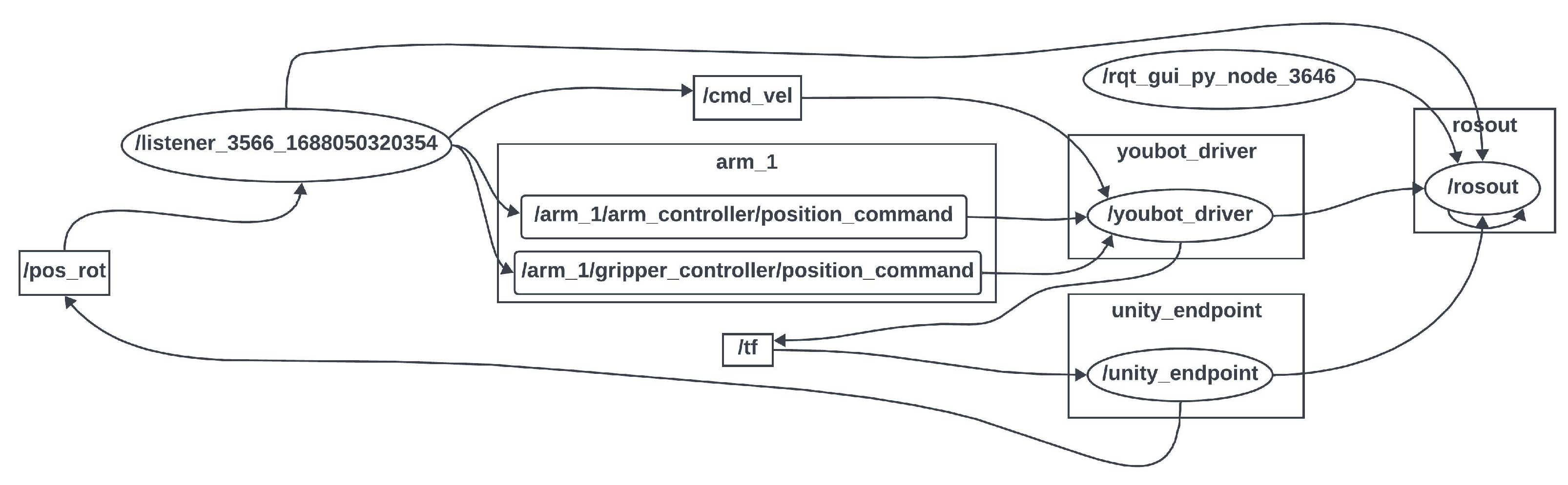
In Figure 14, the node diagram illustrates the data reception process from Unity via the “/unity_endpoint” node, which subscribes to the “/pos_rot" topic defined within the Unity environment. The node responsible for receiving these data is denoted as “/listener”. Its primary function involves processing the incoming data and transforming them into a range that adheres to the upper and lower rotational limits of the physical robot. Once these data undergo processing, they are subsequently published to their respective topics. Specifically, data related to arm control are published to “/arm_1/arm_controller/position_command”, data pertaining to the gripper are transmitted to “/arm_1/gripper_controller/position_command”, and information concerning wheel movement is disseminated via “/cmd_vel”. It is noteworthy that all these data are then routed to the “/youbot_driver” node, which orchestrates movements for both the robot’s arm and the mobile platform.
5.3. Development of User-Centric Virtual Reality Environment for Robot Control
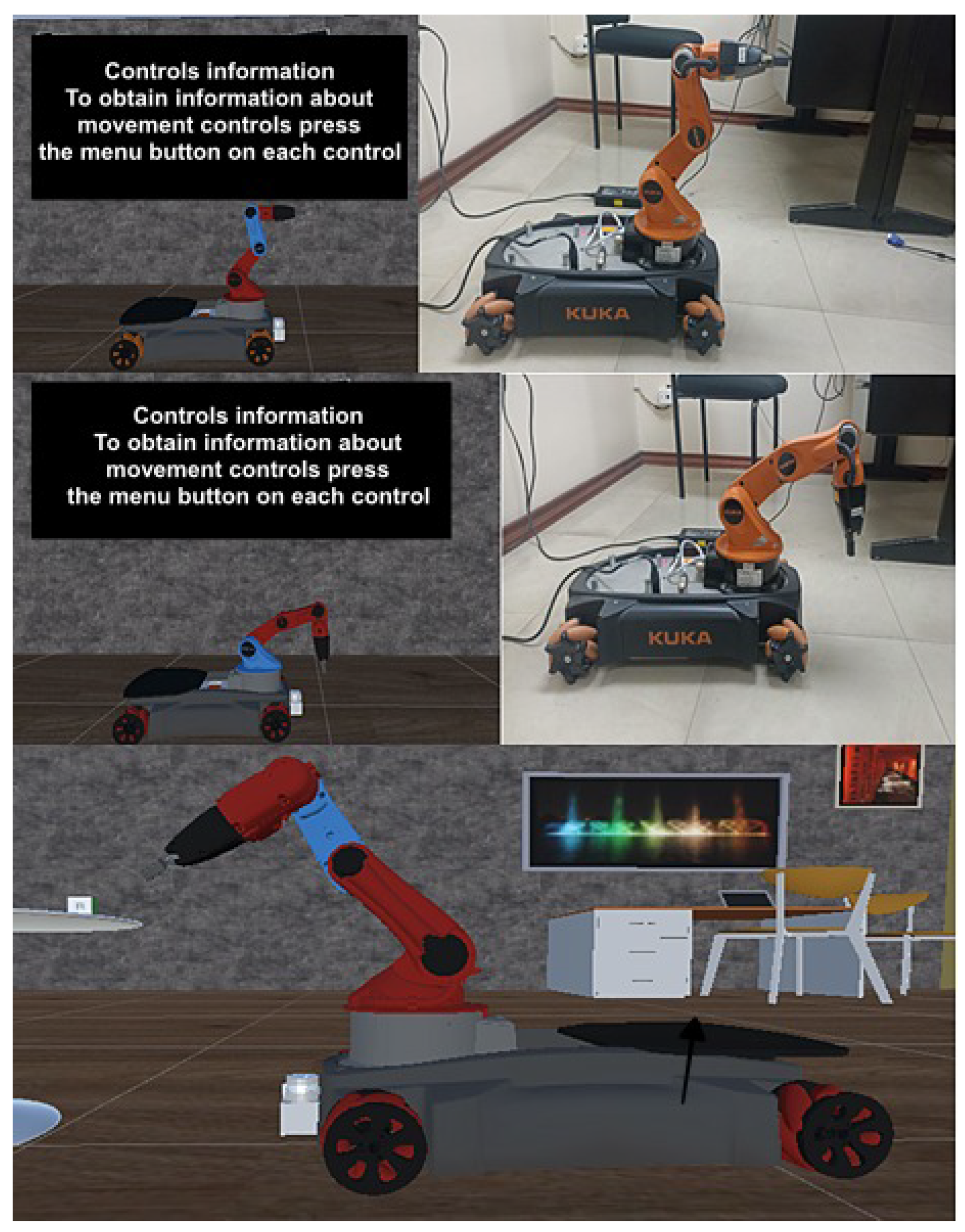
The development of the virtual reality environment for robot control, as shown in Figure 15, has taken into account the guidelines of the work present in [38] and ISO standards of usability [39] of virtual reality, with the aim of ensuring a seamless experience for the user. These regulations and guidelines focus on four fundamental aspects: ease of use, the learning process, user appeal, and the degree of satisfaction.
To enhance ease of use, text panels have been incorporated, describing the functions of each control button, allowing the user to manipulate the robot efficiently. A translation function has also been implemented, making it easier to navigate through the scene without the need for physical movement.
Regarding the learning process, relevant data about the position of the robot’s parts have been provided so that the user can control it precisely. Additionally, a task of picking up and placing objects has been designed, allowing the user to observe the robot’s movement while reaching a goal.
To enhance user engagement, a feature has been implemented that highlights the part or joint of the robot being controlled, providing a clear and visually appealing experience.
User satisfaction when interacting with virtual reality is related to physical comfort. Excessive camera speeds that can cause discomfort, eye fatigue, or motion sickness have been avoided.
Within the virtual reality environment, objects that encapsulate the functionality of the system have been incorporated, with dependency relationships that ensure the proper functioning of each component.
The control of each joint of the robot is carried out using the buttons on the right controller, similar to the control of the mobile platform, which uses the gyroscope of the same controller. Additionally, once the joint movements are completed, it is possible to return them to their initial position using the back button (trigger) on the same controller. On the other hand, the selection of the robot’s joints and the control of translational movements, which allow the person to move closer or farther away from the robot in the virtual reality environment, are performed through the left controller.
5.4. Measuring Robot Movement Time in the Unity VR Environment
To evaluate the effectiveness and user experience of the virtual reality (VR) environment designed for robot control, a task measuring the robot’s time to reach a target needs to be implemented. The overall objectives of guaranteeing a flawless user experience, adhering to usability guidelines, and raising user happiness are all in line with this work. The task developed to measure the usability of the VR platform and the time of the movement of the KUKA youBot robot is detailed below:
Step 1: User interaction. In the initial phase of this task, the user engages with the virtual reality (VR) environment. They are presented with an intuitive VR interface designed to enhance user-friendliness. This interface includes the incorporation of text panels, strategically positioned to offer clear and concise instructions on the functions of every control button available in the VR system. This meticulous design aims to maximize the ease of use, ensuring that users can interact with the VR environment effortlessly. By providing explicit guidance on control functions, users are empowered to manipulate the robot with precision and confidence. The overarching objective here is to establish an environment where users can seamlessly navigate and control the robot, setting the stage for a positive user experience.
Step 2: Setting the goal. Following the initial interaction with the VR environment, users are presented with a goal-setting scenario. Within this scenario, users are supplied with pertinent data about the current positions of various components of the robot. This information equips users with the necessary insights to make informed decisions about their desired robot movement. The primary aim is to engage users in a goal-oriented exercise, where they are tasked with instructing the robot to reach a specific location or target within the virtual environment. The goal-setting step significantly contributes to the learning process, as it provides users with practical, hands-on experience in articulating their intentions to the robot. This not only enhances user engagement but also fosters a deeper understanding of robot control.
Step 3: Task execution. Once the user has formulated their goal and transmitted the corresponding instructions to the VR system, the task moves into the execution phase. At this stage, the VR system orchestrates the robot’s movement, initiating the journey towards the user-defined target location. Simultaneously, a timer is activated to record the elapsed time from the moment the user’s instruction is relayed to the robot to the instant the robot successfully attains the specified goal. The real-time tracking of the robot’s movement provides users with a dynamic visual representation of the robot’s progress towards the set target. This dynamic visualization enhances user engagement, as it offers users immediate feedback on the robot’s response to their commands and enables them to monitor the robot’s movement in real-time.
Step 4: User satisfaction assessment. User satisfaction is a paramount consideration in the VR environment. To ensure a high level of user satisfaction, it is essential to address factors that could potentially lead to user discomfort, eye fatigue, or motion sickness. One critical aspect that requires vigilant attention is the camera speeds during the robot’s movement. It is imperative to maintain these camera speeds within the acceptable comfort limits defined by VR usability standards. Ensuring that users can view and interact with the robot comfortably and without experiencing adverse physical effects is central to maintaining their satisfaction with the VR environment.
Step 5: Data collection and analysis. Throughout the entire task, comprehensive data regarding the time taken by the robot to reach the user-specified goal are systematically recorded and stored for further analysis. These data serve as pivotal performance indicators, offering valuable insights into the effectiveness of the VR environment. They provide a measurable metric for assessing the system’s capability to enable precise control and efficient execution of robotic tasks. Data collection and subsequent analysis also pave the way for potential optimizations and improvements to enhance the user experience and the overall performance of the VR system.
Step 6: Task completion. As the robot successfully reaches the user-defined goal, the recorded time is presented to the user. This final step offers users direct feedback on the efficiency of their instructions and the responsiveness of the VR environment. It provides a tangible result that can be used to evaluate the accuracy and timeliness of the robot’s execution, allowing users to gauge the effectiveness of their control and providing a sense of accomplishment upon task completion.
This task serves as an essential component for evaluating the performance of the VR environment for robot control, ensuring that it meets the established standards of usability and user satisfaction (See Figure 16). By providing a clear metric for measuring the time it takes for the robot to execute user commands, the task contributes to the overall assessment of the VR system’s effectiveness and user experience.
6. Experiments and Results
In the following section, we delve into the comprehensive analysis of the experiments and results obtained in the context of our research. This section is divided into several key aspects, each shedding light on critical facets of the study’s outcomes. Firstly, we investigate “Response Times” to gain insight into the efficiency and reliability of data transmission and execution times within the Unity–ROS framework. Subsequently, we turn our attention to the “Usability of the System”, employing the System Usability Scale (SUS) method to assess the acceptability and satisfaction of users with our virtual reality environment. This section further encompasses an exploration of the “Manipulation of the Robot”, where we gauge the students’ proficiency in controlling the robot, providing an in-depth perspective on their performance levels. Additionally, we delve into “Packet Traffic Analysis” using Wireshark, evaluating the communication robustness and identifying potential packet losses. Lastly, the “Delay in Data” analysis uncovers variations in data delay during robot movement execution, offering insights into the underlying factors contributing to these temporal discrepancies. These findings collectively contribute to a comprehensive understanding of the research’s empirical outcomes.
6.1. Response Times
Data acquisition involves measuring the execution time from when the process is triggered in Unity until the robot’s movement is executed. In the article by Rassolkin A et al. [40], it is indicated that to obtain statistically significant results, one should follow the statistical rule that requires a sample size larger than 30. This rule is based on the central limit theorem, which states that when the sample size is greater than 30, the distribution of sample means approximates a normal distribution regardless of the original data distribution’s shape.
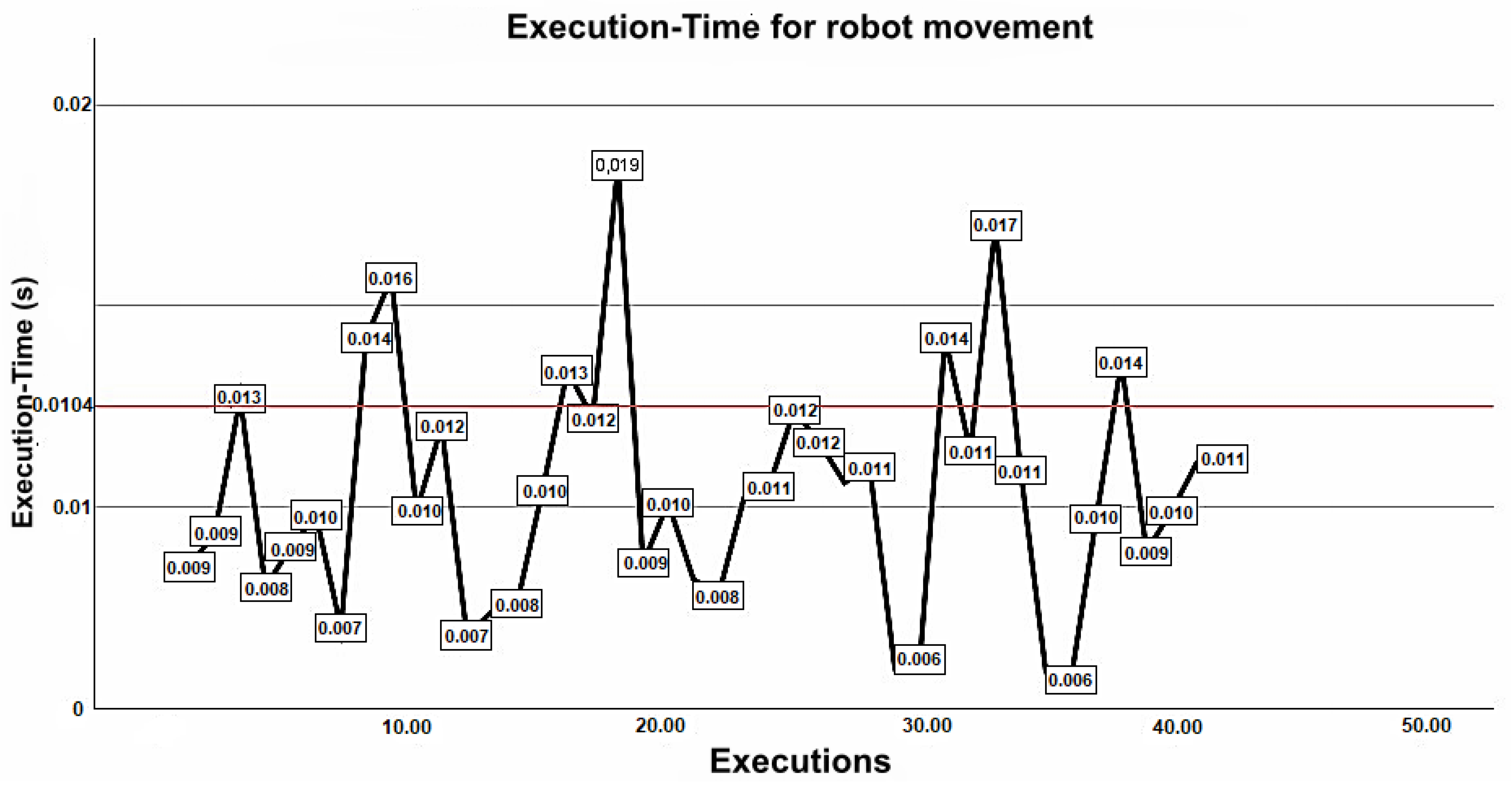
In Figure 17, the response times for various robot movements once the data are processed from Unity are presented. On average, the robot takes approximately 10.4 ms to execute a movement, with a maximum peak of 18.5 ms in the worst-case scenario. It is important to note that this time is influenced by various factors such as network latency, network traffic, and data processing capacity. The standard deviation value of 0.00295 indicates that there is not much dispersion in response times relative to the mean. Since you have a sample size greater than 30, and the data tend to follow a normal distribution resembling a Gaussian curve, you can apply a statistical test known as the Shapiro–Wilk test to validate the data. This is useful for predicting and estimating future values regarding execution times or system performance.
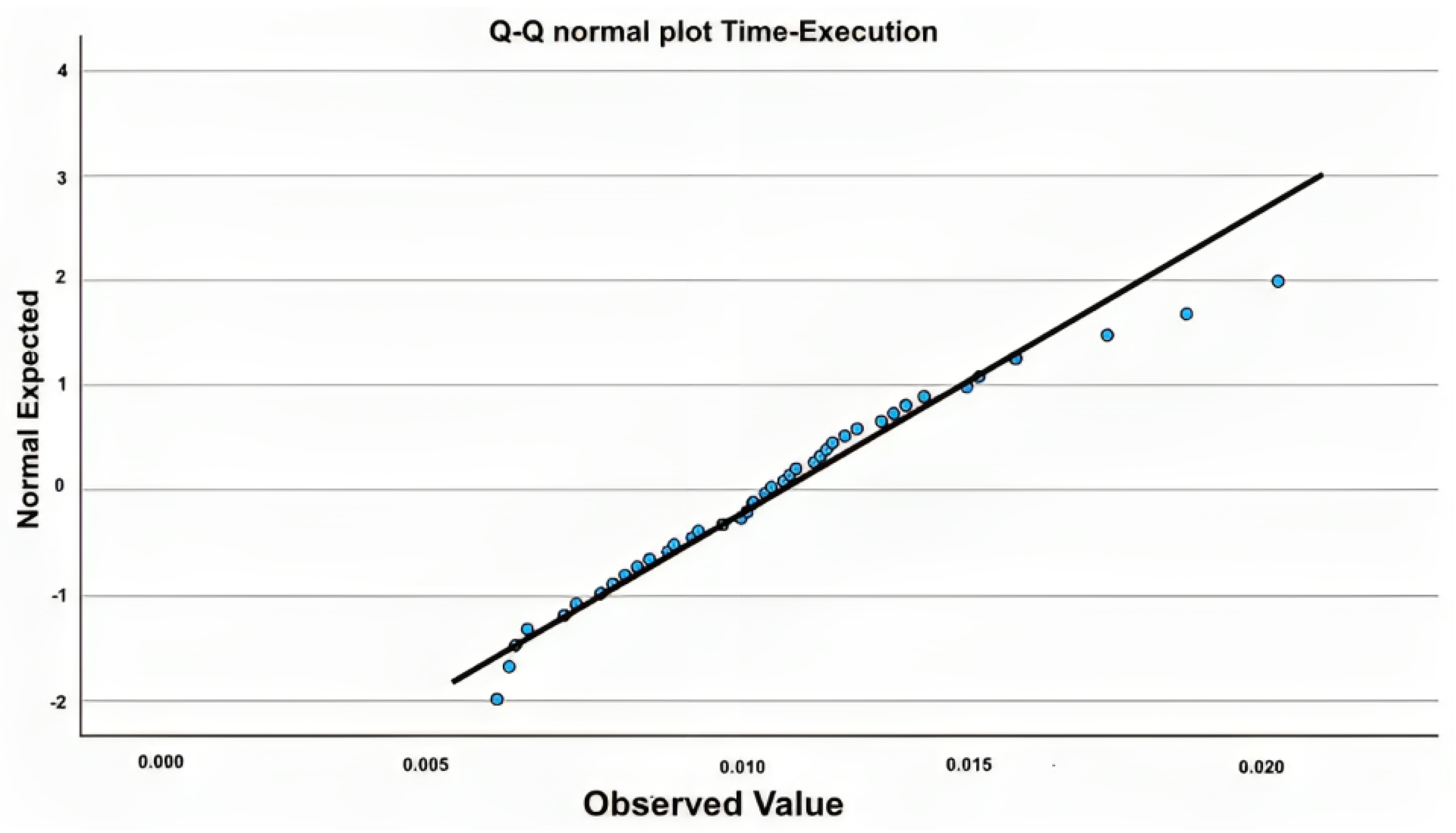
In Figure 18, the Q-Q normal plot compares the quantiles of the data sample with the theoretical quantiles of the distribution being tested. If the data follows a normal distribution, the points on the Q-Q plot will roughly fall along a diagonal line. The more the points deviate from this line, the greater the difference between the sample distribution and a normal distribution. If the points are above the line, it indicates that the sample has heavier tails than a normal distribution. If they are below the line, it indicates that the sample has lighter tails. Using SPSS software version 29.0, the Shapiro–Wilk statistical test is calculated, where the null hypothesis suggests that the data follow a normal distribution, and the alternative hypothesis suggests that the data do not follow a normal distribution. The software is set with a 95% confidence level, indicating a high degree of confidence that the results are representative of the underlying population, and a significance level (alpha) of 5%, which indicates the probability of making a Type I error by incorrectly rejecting a true null hypothesis. The obtained p-value is 0.227, and this test indicates that if the calculated value is greater than 0.05, the null hypothesis is accepted. This ensures that these data are reliable for effective communication between Unity and ROS, as there is not much difference or discrepancy from the calculated mean.
6.2. Usability of the System
Usability is evaluated using the SUS (System Usability Scale) method developed by Blattgerste et al. [41]. This method consists of 10 predefined questions that serve to assess the usability of any system. Responses to each statement follow the Likert scale, so there are five response options for each question, this serves to measure attitudes, opinions, and the level of acceptability of a person on a specific topic. It is generally presented in a series of options ranging from “Strongly Disagree” to “Strongly Agree”, and respondents choose the option that best reflects their opinion or attitude. A survey was administered to a sample of 39 students, and the results obtained are presented in Figure 19, where the horizontal axis represents the number of survey questions, and the vertical axis represents the number of students who chose each response option. Once the survey was completed, the individual score for each question was calculated. It should be noted that odd-numbered questions 1, 3, 5, 7 are positive, and even-numbered questions 2, 4, 6, 8 are negative, as this method frames questions this way to avoid response bias.
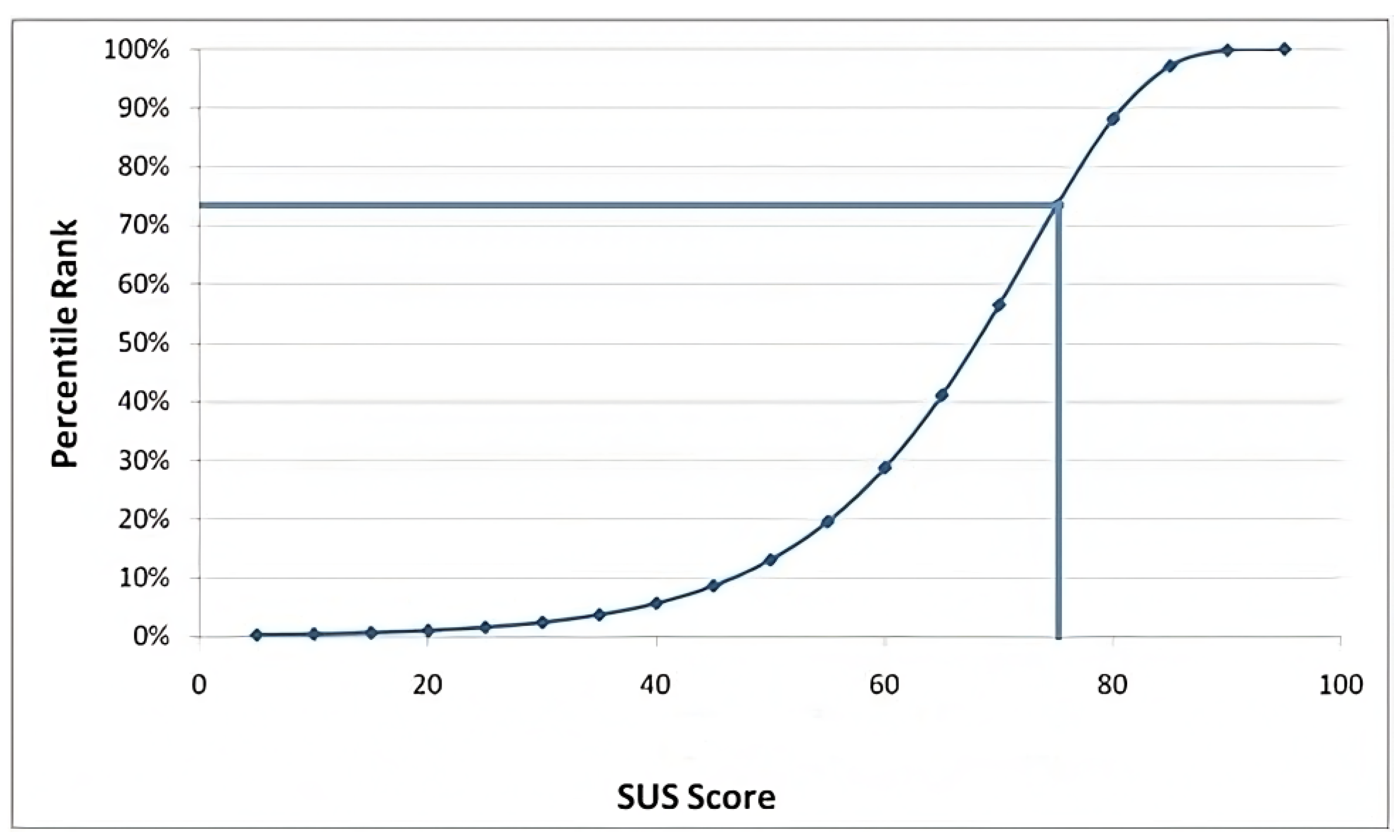
To evaluate the SUS score, you sum the responses from the odd-numbered statements within the Likert scale, subtract 5, sum the responses from the even-numbered statements, and subtract 25. Finally, you add both results and multiply by 2.5. The obtained score results in a score of 75, which indicates a “B” grade with a descriptor of “Good”. The acceptability is “Acceptable”, and the Net Promoter Score (NPS) is “Passive”, indicating user loyalty to the system, meaning they are satisfied with the virtual reality experience. In Figure 20, you can see the percentile distribution of the SUS score, which corresponds to the 73rd percentile. The percentile is useful for understanding the usability of the system. If the SUS score is in a high percentile, it indicates that the majority of users are satisfied with the usability of the system, while a low percentile suggests that several usability aspects need improvement.
6.3. Manipulation of the Robot
The aim of this test is for students to freely control each part of the robot using the virtual reality environment. This test has five performance levels of control, and scores are assigned to each level to determine the achieved control. These scores are assigned based on their proficiency in manipulating the robot, the accuracy, and whether they require supervision or support to reach the goal. The description of each of these levels is presented below:
- Excelent: 5 points (students who demonstrate complete and precise mastery of all parts of the robot. They can move the robot smoothly with high accuracy and dexterity).
- Good: 4 points (students who demonstrate a good mastery in manipulating the robot. Although they may make some minor errors, overall, they can manipulate the robot with precision and efficiency).
- Acceptable: 3 points (students who can control the robot to some extent but may make significant errors. They may require partial guidance and support).
- Limited: 2 points (may struggle to manipulate it correctly and perform tasks accurately. They require constant supervision and assistance to achieve the objectives).
- Low: 1 point (have no control over the robot, struggle significantly to understand robot control, displaying performance well below the expected level).
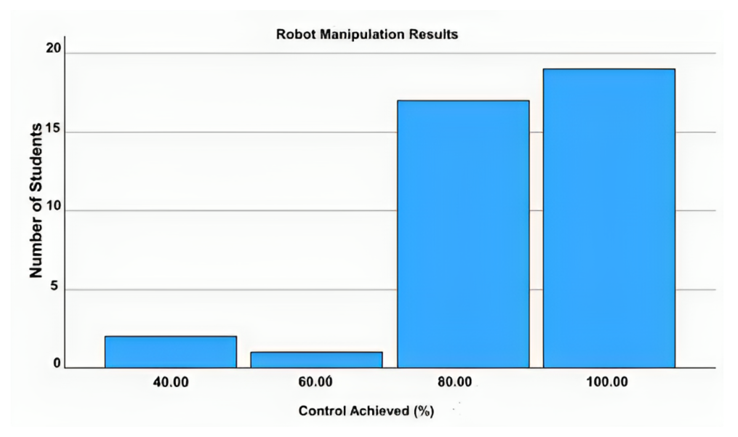
In Figure 21, the results of each student’s robot control performance are presented. There are two students with a 40% control performance, meaning they have difficulties manipulating the robot and require constant supervision. A student has a 60% control performance, indicating they can control the robot to some extent but make significant errors, requiring partial assistance. A total of 17 students have an 80% control performance, meaning they show good mastery of the robot with minor errors that do not affect robot manipulation. Finally, 19 students have a 100% control performance, indicating they can control the robot without any issues, demonstrating great skill and fluency in robot control. The average score is 4.36, considering that 5 is the highest level, which represents an 87.18% mastery of robot control. In other words, students can manipulate the robot with good mastery but may make certain minor errors that do not affect robot control.
6.4. Packet Traffic Analysis
The open-source software Wireshark version 4.2.0 is used to capture packet traffic data. This software allows you to obtain the number of packets processed for the robot’s movement and the time between each of these packets. To capture the packets of interest, a filter is applied to only capture traffic on TCP port 10,000, as this is the port used for communication between Unity and ROS. In Figure 22, you can see the captured packets along with the time elapsed for each packet. It shows the sending of 715 packets from Unity and the capture of 693 packets in ROS, resulting in a total loss of 22 packets. These losses can be attributed to factors like network latency and congestion. The horizontal axis represents the time of capture for each packet, with the last packet captured at 80.35 s. The time elapsed since the previous captured packet was 0.0204 ms. On the vertical axis, the times elapsed between each packet are represented every 100 ms.
6.5. Delay in Data
In Figure 23, the network delay during the execution of robot movements is shown. This graph illustrates the variation in round-trip time (RTT) between sent and received packets. The horizontal axis represents the time elapsed between packets, and the vertical axis displays the RTT value in milliseconds for each packet. The average data delay is 0.115 ms, with a maximum peak value of 1.65 ms, indicating that, at times, packets may experience higher delays than the average. There is also a minimum peak value of 0.032 ms, indicating that, at times, packets may experience very low delays. These variations in delay can be attributed to factors such as hardware performance, as the devices involved can affect performance depending on the hardware used, as well as physical distance between the operator and network congestion.
7. Conclusions and Future Work
The analysis of a robot’s kinematics proves to be a cornerstone in optimizing its performance in various industrial applications. By thoroughly understanding the movements and positions of its joints and end effector, efficient and safe motions can be achieved. Simulation in Gazebo has proven to be an invaluable tool in this process, allowing for tests and experiments that facilitate the understanding of fundamental kinematic concepts, as well as the identification of potential collisions with the environment.
The methodology employed in virtual environments for robot manipulation, which combines technologies like virtual reality and teleoperation, proves to be an effective and versatile solution. The immersive virtual reality interface allows for intuitive and precise control of the robot, with acceptable usability according to the SUS scale. This scalable and adaptable technology holds promising potential in various fields, including industry, medicine, education, and agriculture.
Furthermore, the data obtained through TCP show consistency in robot execution times, with average times staying within acceptable limits. The normal distribution of these data, supported by statistical tests, ensures stability in execution times, which is essential for precise and safe robot control. The implementation of a teleoperation system with virtual reality not only improves the operability of the robot but also provides opportunities for training and risk assessment in virtual environments, thereby reducing exposure to hazardous situations in the real world. Collectively, these conclusions highlight the importance of combining kinematics, virtual reality, and teleoperation in the control and safe management of robots in various applications.
The development of a virtual reality system with improvements in the quality of the experience, latency reduction, and the incorporation of more intuitive user interfaces for more efficient and precise teleoperation is a research area for the future. Additionally, the incorporation of elements of social interaction in virtual reality teleoperation is worth exploring, which could be valuable in applications such as assisting the elderly or distance education. Furthermore, ensuring data transmission security and robot control through ROS Security is another area of future research, especially in critical applications where robots interact with sensitive environments and systems. This helps establish authorization policies to define who can access what resources and perform what actions within the ROS system, ensuring that critical operations are restricted only to authorized users.
Author Contributions
Conceptualization, B.R.G. and M.V.G.; methodology, B.R.G.; software, B.R.G., S.M. and P.A.; validation, M.V.G.; investigation, B.R.G., P.A. and M.V.G.; writing—original draft preparation, B.R.G. and M.V.G.; writing—review and editing, P.A. and M.V.G.; visualization, S.M.; supervision, M.V.G.; funding acquisition, S.M. All authors have read and agreed to the published version of the manuscript.
Funding
This research received no external funding.
Data Availability Statement
Data is unavailable due to privacy restrictions.
Acknowledgments
The authors would like to acknowledge the support received from the Universidad Tecnica de Ambato (UTA) and their Research and Development Department (DIDE) under project PFISEI32. Additionally, the authors would like to express their gratitude to the research network INTELIA, supported by REDU, for their valuable assistance throughout the course of this work. Their collaboration and expertise contributed significantly to the success of the project.
Conflicts of Interest
The authors declare no conflict of interest.
References
- Caiza, G.; Garcia, C.A.; Naranjo, J.E.; Garcia, M.V. Flexible robotic teleoperation architecture for intelligent oil fields. Heliyon 2020, 6, e03833. [Google Scholar] [CrossRef] [PubMed]
- Matsas, E.; Vosniakos, G.C. Design of a virtual reality training system for human–robot collaboration in manufacturing tasks. Int. J. Interact. Des. Manuf. 2017, 11, 139–153. [Google Scholar] [CrossRef]
- Chu, C.Y.; Patterson, R.M. Soft robotic devices for hand rehabilitation and assistance: A narrative review. J. Neuroeng. Rehabil. 2018, 15, 9. [Google Scholar] [CrossRef] [PubMed]
- Bilberg, A.; Malik, A.A. Digital twin driven human–robot collaborative assembly. CIRP Ann. 2019, 68, 499–502. [Google Scholar] [CrossRef]
- Oyekan, J.O.; Hutabarat, W.; Tiwari, A.; Grech, R.; Aung, M.H.; Mariani, M.P.; López-Dávalos, L.; Ricaud, T.; Singh, S.; Dupuis, C. The effectiveness of virtual environments in developing collaborative strategies between industrial robots and humans. Robot.-Comput.-Integr. Manuf. 2019, 55, 41–54. [Google Scholar] [CrossRef]
- Makhataeva, Z.; Varol, H.A. Augmented reality for robotics: A review. Robotics 2020, 9, 21. [Google Scholar] [CrossRef]
- De Abreu, A.; Ozcinar, C.; Smolic, A. Look around you: Saliency maps for omnidirectional images in VR applications. In Proceedings of the 9th International Conference on Quality of Multimedia Experience (QoMEX), Erfurt, Germany, 31 May 2017–2 June 2017. [Google Scholar] [CrossRef]
- Zhang, T.; McCarthy, Z.; Jowl, O.; Lee, D.; Chen, X.; Goldberg, K.; Abbeel, P. Deep imitation learning for complex manipulation tasks from virtual reality teleoperation. In Proceedings of the 2018 IEEE International Conference on Robotics and Automation (ICRA), Brisbane, Australia, 21–25 May 2018; pp. 5628–5635. [Google Scholar] [CrossRef]
- Havard, V.; Jeanne, B.; Lacomblez, M.; Baudry, D. Digital twin and virtual reality: A co-simulation environment for design and assessment of industrial workstations. Prod. Manuf. Res. 2019, 7, 472–489. [Google Scholar] [CrossRef]
- Fernandez, G.; Gutierrez, S.; Ruiz, E.; Perez, F.; Gil, M. Robotics, the New Industrial Revolution. IEEE Technol. Soc. Mag. 2012, 31, 51–58. [Google Scholar] [CrossRef]
- Yang, G.Z.; Bellingham, J.; Dupont, P.E.; Fischer, P.; Floridi, L.; Full, R.; Jacobstein, N.; Kumar, V.; McNutt, M.; Merrifield, R.; et al. The grand challenges of science robotics. Sci. Robot. 2018, 3, eaar7650. [Google Scholar] [CrossRef]
- Romero, D.; Stahre, J.; Wuest, T.; Noran, O.; Bernus, P.; Fast-Berglund, Å.; Gorecky, D. Towards an operator 4.0 typology: A human-centric perspective on the fourth industrial revolution technologies. In Proceedings of the International Conference on Computers and Industrial Engineering (CIE46), Tianjin, China, 29–31 October 2016; pp. 29–31. [Google Scholar]
- Xu, S.; Moore, S.; Cosgun, A. Shared-control robotic manipulation in virtual reality. In Proceedings of the 2022 International Congress on Human-Computer Interaction, Optimization and Robotic Applications (HORA), Ankara, Turkey, 9–11 June 2022. [Google Scholar] [CrossRef]
- Luo, Y.; Wang, J.; Shi, R.; Liang, H.N.; Luo, S. In-Device Feedback in Immersive Head-Mounted Displays for Distance Perception During Teleoperation of Unmanned Ground Vehicles. IEEE Trans. Haptics 2022, 15, 79–84. [Google Scholar] [CrossRef]
- Julio Becerra, J.R.; Peñaloza, M.E.; Rodríguez, J.E.; Chacón, G.; Martínez Molina, J.A.; Saquipay Ortega, H.V.; Castañeda Morales, D.H.; Pesantez Placencia, X.M.; Salazar, J.; Añez, R.; et al. La realidad virtual como herramienta en el proceso de aprendizaje del cerebro. Arch. Venez. Farmacol. Ter. 2019, 38, 98–107. [Google Scholar]
- Sousa Ferreira, R.; Campanari Xavier, R.A.; Rodrigues Ancioto, A.S. Virtual reality as a tool for basic and vocational education. Rev. Cient. Gen. Jose Maria Cordova 2021, 19, 223–241. [Google Scholar]
- Zhou, T.; Zhu, Q.; Du, J. Intuitive robot teleoperation for civil engineering operations with virtual reality and deep learning scene reconstruction. Adv. Eng. Inform. 2020, 46, 101170. [Google Scholar] [CrossRef]
- Gorjup, G.; Dwivedi, A.; Elangovan, N.; Liarokapis, M. An Intuitive, Affordances Oriented Telemanipulation Framework for a Dual Robot Arm Hand System: On the Execution of Bimanual Tasks. In Proceedings of the 2019 IEEE/RSJ International Conference on Intelligent Robots and Systems (IROS), Macau, China, 3–8 November 2019; pp. 3611–3616. [Google Scholar] [CrossRef]
- Endsley, M.R. Toward a theory of situation awareness in dynamic systems. Hum. Factors 1995, 37, 32–64. [Google Scholar] [CrossRef]
- Scholtz, J.; Antonishek, B.; Young, J. Evaluation of a human-robot interface: Development of a situational awareness methodology. In Proceedings of the 37th Annual Hawaii International Conference on System Sciences, Big Island, HI, USA, 5–8 January 2004; Volume 37, pp. 2077–2086. [Google Scholar]
- Arthur, K.W. Effects of Field of View on Performance with Head-Mounted Displays; The University of North Carolina at Chapel Hill: Chapel Hill, NC, USA, 2000. [Google Scholar]
- Zhou, T.; Xia, P.; Ye, Y.; Du, J. Embodied Robot Teleoperation Based on High-Fidelity Visual-Haptic Simulator: Pipe-Fitting Example. J. Constr. Eng. Manag. 2023, 149, 13916. [Google Scholar] [CrossRef]
- Stotko, P.; Krumpen, S.; Schwarz, M.; Lenz, C.; Behnke, S.; Klein, R.; Weinmann, M. A VR system for immersive teleoperation and live exploration with a mobile robot. In Proceedings of the 2019 IEEE/RSJ International Conference on Intelligent Robots and Systems (IROS), Macau, China, 3–8 November 2019; pp. 3630–3637. [Google Scholar]
- Riva, G.; Mantovani, F.; Capideville, C.S.; Preziosa, A.; Morganti, F.; Villani, D.; Gaggioli, A.; Botella, C.; Alcañiz, M. Affective interactions using virtual reality: The link between presence and emotions. Cyberpsychol. Behav. 2007, 10, 45–56. [Google Scholar] [CrossRef]
- Peppoloni, L.; Brizzi, F.; Avizzano, C.A.; Ruffaldi, E. Immersive ROS-integrated framework for robot teleoperation. In Proceedings of the 2015 IEEE Symposium on 3D User Interfaces (3DUI), Arles, France, 23–24 March 2015; pp. 177–178. [Google Scholar]
- Caiza, G.; Bonilla-Vasconez, P.; Garcia, C.A.; Garcia, M.V. Augmented reality for robot control in low-cost automation context and IoT. In Proceedings of the 25th IEEE International Conference on Emerging Technologies and Factory Automation (ETFA), Vienna, Austria, 8–11 September 2020. [Google Scholar]
- Blumenthal, S.; Shakhimardanov, A.; Nowak, W. KUKA youBot User Manual; Locomotec: Augsburg, Germany, 2012; p. 7. [Google Scholar]
- Botev, J.; Lera, F.J.R. Immersive Robotic Telepresence for Remote Educational Scenarios. Sustainability 2021, 13, 4717. [Google Scholar] [CrossRef]
- Rakita, D.; Mutlu, B.; Gleicher, M. Effects of onset latency and robot speed delays on mimicry-control teleoperation. In Proceedings of the HRI’20: 2020 ACM/IEEE International Conference on Human-Robot Interaction, Cambridge, UK, 23–26 March 2020. [Google Scholar]
- Kim, E.; Peysakhovich, V.; Roy, R.N. Impact of communication delay and temporal sensitivity on perceived workload and teleoperation performance. In Proceedings of the ACM Symposium on Applied Perception 2021, Virtual, 16–17 September 2021; pp. 1–8. [Google Scholar]
- Di Lanzo, J.A.; Valentine, A.; Sohel, F.; Yapp, A.Y.; Muparadzi, K.C.; Abdelmalek, M. A review of the uses of virtual reality in engineering education. Comput. Appl. Eng. Educ. 2020, 28, 748–763. [Google Scholar] [CrossRef]
- Peña-Tapia, E.; Roldán, J.J.; Garzón, M.; Martín-Barrio, A.; Barrientos, A. Interfaz de control para un robot manipulador mediante realidad virtual. In Proceedings of the XXXVIII Jornadas de Automática, Gijón, Spain, 6–8 September 2017; Universidade da Coruña, Servizo de Publicacións: Corunha, Spain, 2020. [Google Scholar] [CrossRef]
- Meshkov, A.; Gromov, V. Adaptive nonlinear motion parameters estimation algorithm for digital twin of multi-link mechanism motion trajectory synthesis. Sci. Tech. J. Inf. Technol. Mech. Opt. 2022, 22, 889–895. [Google Scholar] [CrossRef]
- Nagatani, K.; Tachibana, S.; Sofne, M.; Tanaka, Y. Improvement of odometry for omnidirectional vehicle using optical flow information. In Proceedings of the 2000 IEEE/RSJ International Conference on Intelligent Robots and Systems (IROS 2000) (Cat. No.00CH37113), Takamatsu, Japan, 31 October–5 November 2000. [Google Scholar] [CrossRef]
- Ghaf-Ghanbari, P.; Taghizadeh, M.; Mazare, M. Kinematic and dynamic performance evaluation of a four degrees of freedom parallel robot. Amirkabir J. Mech. Eng. 2021, 53, 2055–2072. [Google Scholar]
- Dwiputra, R.; Zakharov, A.; Chakirov, R.; Prassler, E. Modelica model for the youBot manipulator. In Linköping Electronic Conference Proceedings, Proceedings of the 10th International Modelica Conference, Lund, Sweden, 10–12 March 2014; Linköping University Electronic Press: Linköping, Sweden, 2014. [Google Scholar] [CrossRef]
- Müggler, E.; Fässler, M.; Scaramuzza, D.; Huck, S.; Lygeros, J. Torque Control of a KUKA youBot Arm. Master’s Thesis, University of Zurich, Zurich, Switzerland, 2013. [Google Scholar]
- Yeu, T.K.; Han, J.B.; Lee, Y.J.; Park, D.G.; Kim, S.S.; Hong, S. Preliminary Study on DEVELOPMENT of CPOS(cyber physical operation system) for underwater robots. In Proceedings of the OCEANS 2023, Limerick, Ireland, 5–8 June 2023. [Google Scholar] [CrossRef]
- Quiñones, D.; Rusu, C.; Roncagliolo, S.; Rusu, V.; Collazos, C.A. Formalizing the process of usability heuristics development. In Advances in Intelligent Systems and Computing; Springer International Publishing: Berlin/Heidelberg, Germany, 2016; pp. 1279–1282. [Google Scholar] [CrossRef]
- Rassolkin, A.; Rjabtsikov, V.; Kuts, V.; Vaimann, T.; Kallaste, A.; Asad, B.; Partyshev, A. Interface Development for Digital Twin of an Electric Motor Based on Empirical Performance Model. IEEE Access 2022, 10, 15635–15643. [Google Scholar] [CrossRef]
- Blattgerste, J.; Behrends, J.; Pfeiffer, T. A web-based analysis toolkit for the system usability scale. In Proceedings of the 15th International Conference on PErvasive Technologies Related to Assistive Environments, ACM, Corfu, Greece, 29 June–1 July 2022. [Google Scholar] [CrossRef]
Figure 1.
Geometric dimensions of the mobile platform.

Figure 2.
Visualization of parameters and governing wheel roller angles, with a shaded platform depicting translational and rotational movements.
Figure 2.
Visualization of parameters and governing wheel roller angles, with a shaded platform depicting translational and rotational movements.

Figure 3.
Geometrical parameters of the KUKA youBot arm, illustrating key dimensions and features, including arm length and end-effector specifications, providing a comprehensive overview of the arm’s structural characteristics.
Figure 3.
Geometrical parameters of the KUKA youBot arm, illustrating key dimensions and features, including arm length and end-effector specifications, providing a comprehensive overview of the arm’s structural characteristics.

Figure 4.
Reference frame positioning in robotic arm kinematics, highlighting the assignment at each joint and the fixed global reference frame at the base.
Figure 4.
Reference frame positioning in robotic arm kinematics, highlighting the assignment at each joint and the fixed global reference frame at the base.

Figure 5.
Kinematics class diagram.

Figure 6.
Kinematics graphical interface.

Figure 7.
Robotic arm control class diagram.

Figure 8.
Arm movement in Gazebo.

Figure 9.
Class diagram of mobile platform movement.

Figure 10.
Linear and rotational movement.

Figure 11.
Tracking system architecture.

Figure 12.
Scheme of the virtual reality teleoperation system.

Figure 13.
Communication class diagram.

Figure 14.
ROS RQT diagram.

Figure 15.
Robot control within the virtual reality environment.

Figure 16.
Implementation of the task for robot movement using the VR environment.

Figure 17.
Response times for robot movements. The red line represents the average time for the processing of the robot’s movements.
Figure 17.
Response times for robot movements. The red line represents the average time for the processing of the robot’s movements.

Figure 18.
Shapiro–Wilk normality test.

Figure 19.
Results of system usability.

Figure 20.
Distribution of SUS score.

Figure 21.
Results of robot control performance.

Figure 22.
Packet traffic capture.

Figure 23.
Delay in data.


Table 1.
DH parameters.
| Links | d | a | ||
|---|---|---|---|---|
| 1 | 2.94 | 0.147 | 0.0330 | |
| 2 | 1.12 | 0 | 0.1550 | 0 |
| 3 | −2.54 | 0 | 0.1350 | 0 |
| 4 | 3.35 | 0 | 0 | |
| 5 | 2.92 | 0.2175 | 0 | 0 |
Table 2.
Position and orientation data.
| Links positions | |
|---|---|
| arm_joint_1 | 2.9372 |
| arm_joint_2 | 1.2772 |
| arm_joint_3 | −2.5586 |
| arm_joint_4 | 0.1226 |
| arm_joint_5 | 0 |
| End effector position coordinates | |
| x | −0.1449 |
| y | −0.0017 |
| z | 0.4422 |
| End effector orientation | |
| x | 1.4023 |
| y | −1.3495 |
| z | −1.3939 |
Table 3.
Rotational limits of the arm.
| Link | Name | Lower Limit (Rad) | Upper Limit (Rad) |
|---|---|---|---|
| 1 | arm_joint_1 | 0.0100692 | 5.84014 |
| 2 | arm_joint_2 | 0.0100692 | 2.61799 |
| 3 | arm_joint_3 | −5.02655 | −0.015708 |
| 4 | arm_joint_4 | 0.0221239 | 3.4292 |
| 5 | arm_joint_5 | 0.110619 | 5.64159 |
Disclaimer/Publisher’s Note: The statements, opinions and data contained in all publications are solely those of the individual author(s) and contributor(s) and not of MDPI and/or the editor(s). MDPI and/or the editor(s) disclaim responsibility for any injury to people or property resulting from any ideas, methods, instructions or products referred to in the content. |
© 2023 by the authors. Licensee MDPI, Basel, Switzerland. This article is an open access article distributed under the terms and conditions of the Creative Commons Attribution (CC BY) license (https://creativecommons.org/licenses/by/4.0/).
Share and Cite
MDPI and ACS Style
Galarza, B.R.; Ayala, P.; Manzano, S.; Garcia, M.V. Virtual Reality Teleoperation System for Mobile Robot Manipulation. Robotics 2023, 12, 163. https://doi.org/10.3390/robotics12060163
AMA Style
Galarza BR, Ayala P, Manzano S, Garcia MV. Virtual Reality Teleoperation System for Mobile Robot Manipulation. Robotics. 2023; 12(6):163. https://doi.org/10.3390/robotics12060163
Chicago/Turabian StyleGalarza, Bryan R., Paulina Ayala, Santiago Manzano, and Marcelo V. Garcia. 2023. "Virtual Reality Teleoperation System for Mobile Robot Manipulation" Robotics 12, no. 6: 163. https://doi.org/10.3390/robotics12060163
Note that from the first issue of 2016, this journal uses article numbers instead of page numbers. See further details here.