Article

The Claw: An Avian-Inspired, Large Scale, Hybrid Rigid-Continuum Gripper

1
Department of Electrical and Computer Engineering, Clemson University, Clemson, SC 29634, USA
2
Department of Mechanical Engineering, Clemson University, Clemson, SC 29634, USA
*
Author to whom correspondence should be addressed.
These authors contributed equally to this work.
Robotics 2024, 13(3), 52; https://doi.org/10.3390/robotics13030052
Submission received: 12 February 2024 / Revised: 14 March 2024 / Accepted: 14 March 2024 / Published: 16 March 2024
(This article belongs to the Special Issue Intelligent Bionic Robots)

Abstract

:
Most robotic hands have been created at roughly the scale of the human hand, with rigid components forming the core structural elements of the fingers. This focus on the human hand has concentrated attention on operations within the human hand scale, and on the handling of objects suitable for grasping with current robot hands. In this paper, we describe the design, development, and testing of a four-fingered gripper which features a novel combination of actively actuated rigid and compliant elements. The scale of the gripper is unusually large compared to most existing robot hands. The overall goal for the hand is to explore compliant grasping of potentially fragile objects of a size not typically considered. The arrangement of the digits is inspired by the feet of birds, specifically raptors. We detail the motivation for this physical hand structure, its design and operation, and describe testing conducted to assess its capabilities. The results demonstrate the effectiveness of the hand in grasping delicate objects of relatively large size and highlight some limitations of the underlying rigid/compliant hybrid design.

1. Introduction

In a world largely shaped by the capabilities of human hands, it has long been an aspiration of the robotics community to match the dexterity and versatility of human hands [1,2,3,4]. Compliant mechanisms represent a class of robotic structures with potential to mimic the strength of anthropomorphic hands while expanding the dexterity of the grip [5,6,7]. Soft robotic grippers offer high dexterity at the cost of repeatability and strength [8,9], and show good versatility for environment applicability [10,11].
In this paper we introduce a new compliant robot gripper, termed the Claw. The Claw is novel in three main aspects: (1) it is of an unusually large size with respect to most robot grippers; (2) its design is inspired by the anatomy (feet) of birds; and (3) it features a novel mix of continuum and rigid elements. Collectively, these qualities enable the hand to demonstrate adaptive grasping across a range of objects typically outside the capabilities of robot hands.
The Claw notably combines directly actuated rigid elements (enabling strong grasps such as with the Barrett Hand [12]) with compliant continuum elements, which provide inherent structural compliance and hence enhance grasp robustness without the need for specialized embedded sensors. In relation to soft robotic grippers, continuum robotic elements, as featured in the Claw, have a unique ability in relation to the manipulation of objects. Often drawing inspiration from cephalopods [13], continuum robots are able to use their inherent compliance to perform whole-body grasping [14,15], which sees the continuum structure conforming one or more continuum sections to objects and then using other portions of their body to carry out manipulation. Continuum segments have been shown to create fully continuum grippers similar in dexterity to soft grippers [16].
The hybrid combination of rigid and continuum elements forming the digits of The Claw is unique to the best of our knowledge. In classifying existing robot hands, review articles [17,18] classify digits as either rigid (possibly with flexibility in the joints) or soft continuous. The combination of rigid and soft elements is cited as a future challenge in the review article [19]. Robot hand hardware combining rigid and compliant elements and described as hybrid have still formed the digits themselves from rigid elements, and only included passive compliance in the transmission, e.g., [20,21], or in fingertip pads, e.g., [22]. The Claw instead combines both rigid and compliant continuum elements as active parts of the digits themselves.
Humans and invertebrates have not been the only biological examples inspiring robotic grippers. Avian hind limb anatomy has also been studied and used to create robotic grippers [23,24]. Of particular interest with the rise of unmanned aerial vehicles has been the inspiration of bird foot anatomy for perching and stability of lightweight systems [25,26,27,28,29]. Biological inspiration has also found use for climbing and adherence to the side of vertical surfaces [30,31].
The Claw is bio-inspired rather than biomimetic, in the sense that its design is generally inspired by bird feet, but directly copying the design from biology is not the intent. The goal instead is to capture the adaptability of avian limbs (feet), and to reproduce this adaptability in a hybrid rigid/compliant robot structure. This aspect of bioinspiration guided the topology of the design—number and relative placement of digits, and their general range of motion—but not specifically the selection and placement of actuators. Similarly to classical robotic hands such as the Salisbury hand [32] and the MIT/Utah hand [33], the Claw features three digits facing an opposable digit.
In contrast to these and other tendon-actuated robot hands, such as the Robonaut hand [34], the Claw is actuated via a combination of direct motor and pneumatic actuation. Pneumatic actuation of dexterous robot hands and grippers has been demonstrated previously [4,35,36]. However, as observed in the review article [37], in the literature either pneumatic or electric actuation has been implemented. The Claw features both modalities.
Furthermore, the Claw is significantly larger than any of these robot hands, with a workspace up to ten times greater, enabling the grasp of a class of larger objects. The Claw is explicitly designed to grasp and handle objects which are larger, in terms of volume, than objects current robot hands can handle. A key goal is to expand the scope of robot grippers beyond the current class of objects considered, as summarized for example in the benchmark set in [38]. The set of objects in [38] is an excellent resource, which can be used across a wide range of robot hands and grasping research. However, the utility of such benchmarks in our case is limited, as the Claw is explicitly designed to grasp and handle objects which are larger than any of the objects in the benchmark dataset of the above paper.
Herein, we show that the Claw is capable of adaptive and gentle grasping of a range of relatively large objects outside the scope of conventional robot grippers. The advantage of the hybrid rigid/continuum gripper design in facilitating adaptive grasping is demonstrated. In addition, cases wherein the gripping performance was inadequate give insight into potential inadequacies in the hybrid design, and ways to solve those issues.
The remainder of the paper is organized as follows: Section 2 details the physical construction of the Claw alongside the biological inspiration behind design choices. Section 3 describes experiments to explore the capabilities and unique properties of the hybrid rigid-continuum manipulator. Finally, discussion and conclusions are presented in Section 4 and Section 5, respectively.

2. Materials and Methods

In considering avian physiology, there is a diversity of hind limb morphotypes that appear to have adapted to benefit the various bird species in their daily activities [39], including activities relevant to robot manipulation such as perching and capturing of prey. Two particular hind limb morphotypes of interest in considering the capture and manipulation of objects are that of anisodactyl and raptorial morphotypes, which feature three forward facing digits opposed by a single rearward facing digit, an example of which can be seen in the top image of Figure 1. The Claw, introduced in this work and seen in the bottom of Figure 1, is a large scale robotic gripper combining the use of continuum and rigid segments in a design that is inspired by the functionality of these classes of avian pedal morphotypes. The remainder of this section details the design and assembly of the Claw, as well as the actuation and accompanying control elements necessary to operate the gripper.

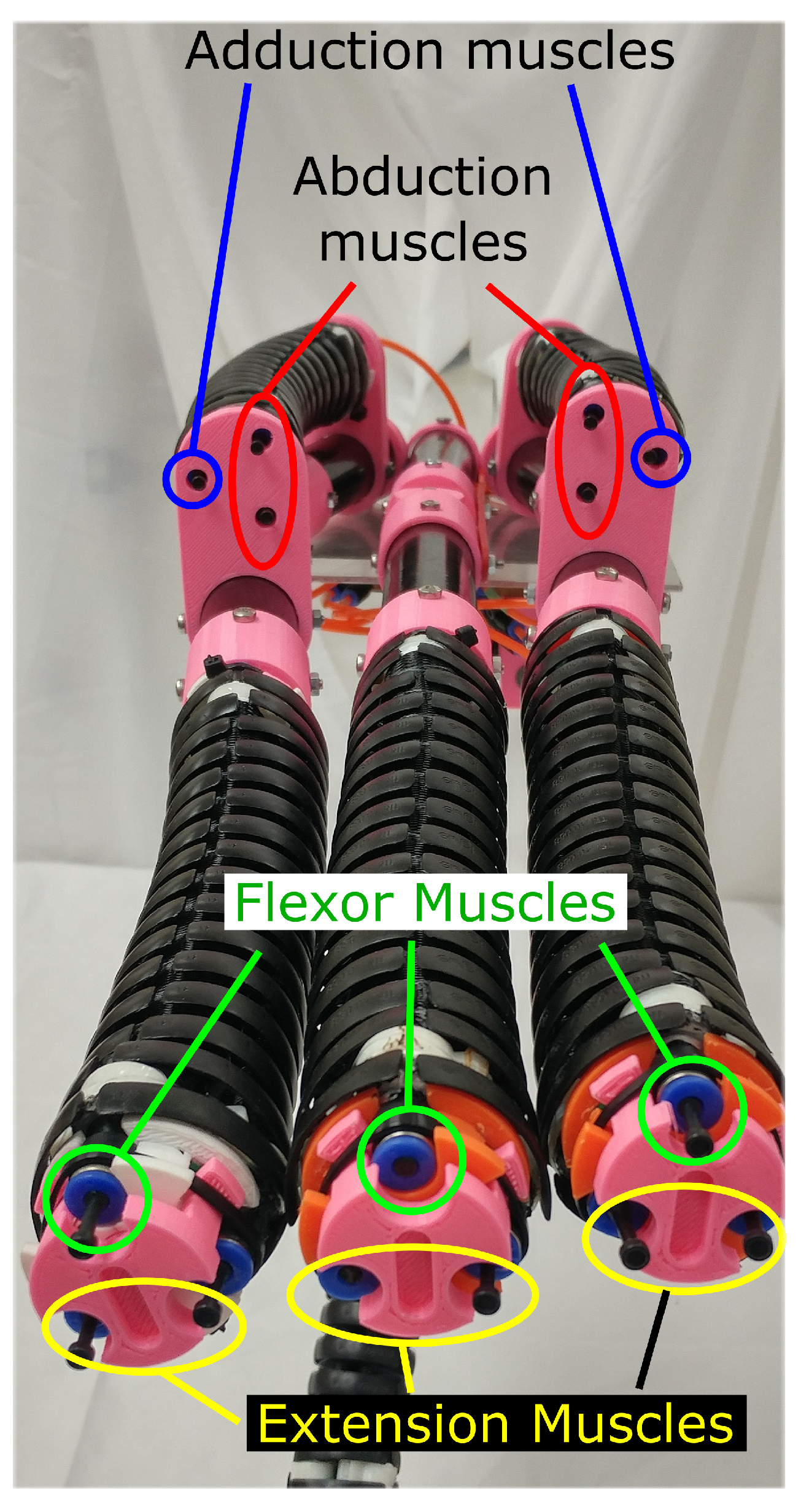
2.1. Mechanical Design and Assembly

Drawing its origin from avian inspirations, wherein which most birds have four digits per foot, the Claw features three forward facing digits and one rearward facing digit as labeled in Figure 2. The outermost forward facing digits consist of two continuum Sections (0.23 m in length), two rigid segments (0.2 m in length), and one revolute joint, the decomposition of which can be seen in Figure 3. The distal most continuum section mimics flexion of biological digits and is useful for encircling of objects. The compliance of the continuum section allows it to conform to various object geometries or other compliant objects. The proximal continuum section sits above the revolute joint at the base of the digit and is used to drive the abductive and adductive movement of the Claw, enabling the manipulator to spread and narrow its grip. The placement of the continuum section above the revolute joint creates a mechanism that is compliant in the plane common to the three forward facing digits while providing rigidity and strength in the direction that external loads would be applied when grasping objects (namely forces into or outward from the “palm”). The rigid segments, acting as reinforcing “bones”, add stability and strength between the continuum sections, which are relatively weak given their compliant nature. Unlike the outer forward facing digits, the middle forward facing digit of the Claw consists of only one continuum section—to drive flexion—and two rigid segments. As with the outside digits, there is a revolute joint connecting the two rigid segments, but in the case of the middle digit it is constrained to not rotate in the initial work presented here. Future efforts may explore the addition of a continuum section above the middle revolute joint to accompany the outer digits.
The continuum sections used in this work are pneumatically driven continuum sections comprised of three extending McKibben muscles and a fixed-length backbone constructed of universal joints. These muscles were selected to be identical to those designed for and reported in [41] due to their mechanical properties satisfying our design requirements. This choice simplified systems integration and control, at the cost of reduced grasp strength (physical restrictions on input pressure) compared to the construction of sections specifically dedicated to the Claw. By pairing two of the three muscles together and utilizing the fixed backbone length, we approximated a planar pair of opposing muscle groups with a single continuum section. We applied this approximation of antagonistic muscles to mimic the adductive/abductive and flexion/extension motions found in biological appendages. The four muscle groups are depicted in Figure 4 as they are assigned in the forward facing digits.
The backward facing digit, denoted as the “thumb” through the remainder of this work, is assembled using one continuum section—for flexion/extension—and one rigid segment (0.25 m in length). The thumb contains the only motor in the gripper in order to drive the opening and closing of the thumb with respect to the core assembly. The DC motor is paired with a planetary gear box that then drives a worm gear assembly (shown in Figure 5), to swing the thumb toward and away from the forward facing digits.
The materials used for the main build of the Claw were chosen to increase strength and decrease weight. Carbon fiber tubing (outer diameter 3.45 × 10 2 m) was ultimately chosen for the rigid segments within the digits because of its high strength to weight ratio. We considered creating these element via 3D printing, but rejected that option due to concerns about durability. The continuum and rigid sections were connected using custom 3D-printed parts that were designed using SolidWorks. The pieces used in the construction of the digits can be seen in Figure 3.
Talons that mimic the appearance and geometry of raptor talons were added to the end of the distal continuum sections, as depicted in Figure 1. The optional talons were comprised of 3D-printed plastic and designed to be easily removable as they were sharp enough to potentially damage fragile objects. The talons were originally added for cosmetic effect, to emphasize the biological (avian) inspiration. However, in several experiments, the claws did assist in maintaining grasps, providing additional physical constraints (form closure).

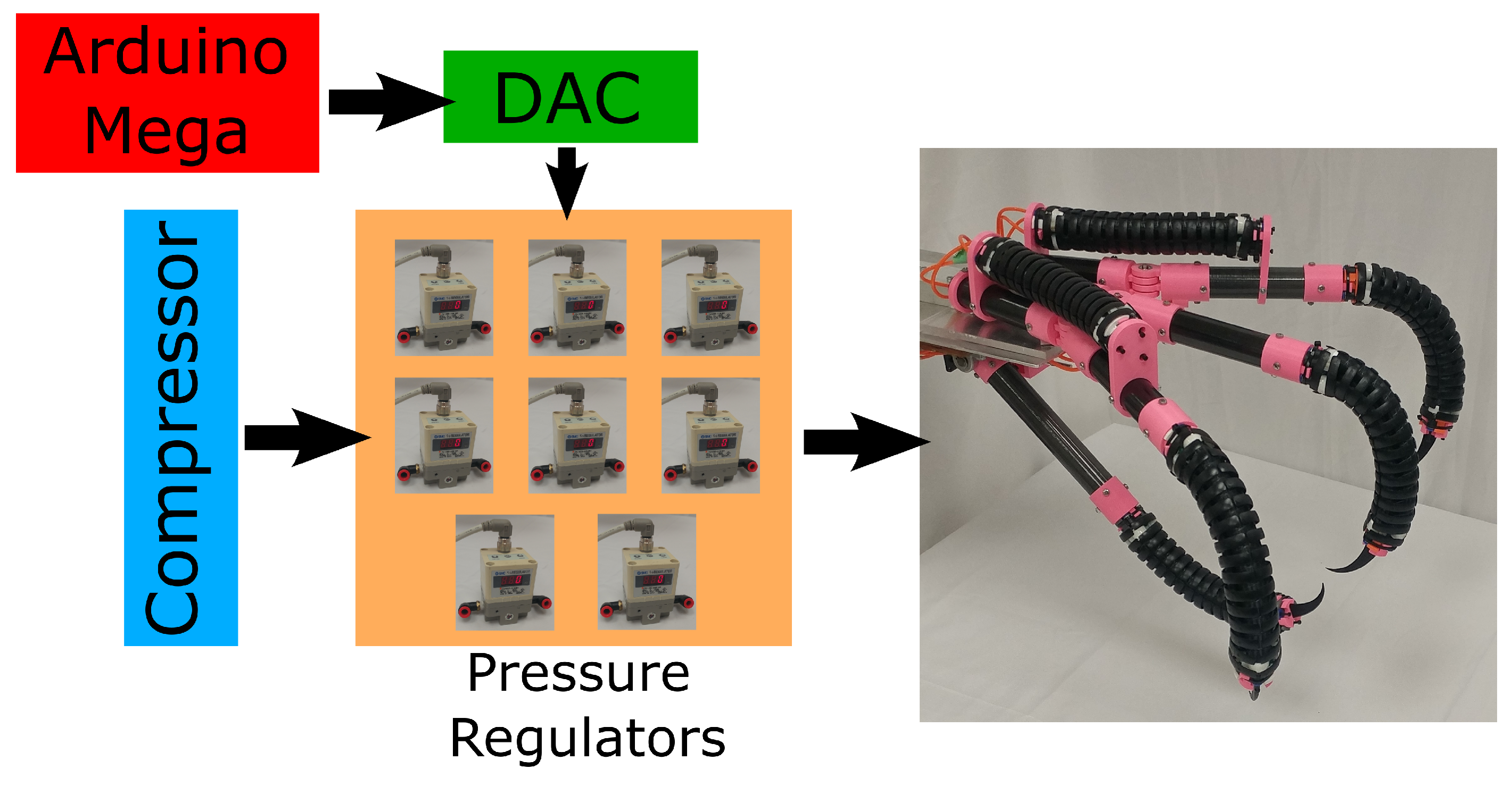
2.2. System Components and Function

In support of the rigid-continuum structure described above, the Claw has at its core an Arduino Mega microcontroller to drive the actuation system. As the McKibben muscles within the continuum sections are pneumatically actuated, the Claw utilizes an air compressor and a series of pressure regulators (SMC ITV1050-31N1N4, manufacturer SMC Corporation, Tokyo, Japan) to extend and bend the continuum sections. The regulators are directed by the Arduino Mega via a pair of Digital-to-Analog Converters (DAC, Adafruit MCP4728, Adafruit Industries, New York, NY, USA), each of which can interface with four pressure regulators. The microcontroller is also responsible for driving the thumb’s DC motor through a standard DC motor driver (Cytron MD10C, Cytron, Penang, Malaysia). A simplified diagram of the pneumatic system is presented in Figure 6. Not depicted is an optional interface consisting of a series of potentiometers to control the pressures within the various muscles groups and a momentary rocker switch that actuates the thumb motor to open or close. Control of the gripper is simple and conducted by operating the rocker to activate the thumb motor, and dials of the potentiometers to command the input pressures to the other digit actuators. The interface refresh rate was 20 Hz.
There are six essential regulators used for the Claw. The first two regulators separately drive the abduction and adduction of the outer talons. A second pair of regulators is used to drive the flexion and extension of the forward facing digits, and finally, a third pair controls the flexion and extension of the thumb. The maximum pressure that the regulators deliver to the flexion driving muscles is 276 kpa. The abduction and adduction driving muscles receive a maximum pressure of 207 kpa.
In addition to the six movements described above, two additional regulators are available to change the direction of flexion for the outer talons and thumb to a plane that does not align with the plane of the digit. This particular motion breaks from the traditional movement of biological digits, which typically occupy a single plane of bending, but could allow for more traditional robotic grasps like a cylindrical grasp while still spreading the digits away from the center of the gripper. Operational specifications of the Claw are summarized in Table 1.

3. Results

In this section, we present a series of preliminary experiments that highlight the range of motion of the gripper and qualitatively assess the functionality of the Claw as a large scale gripper.

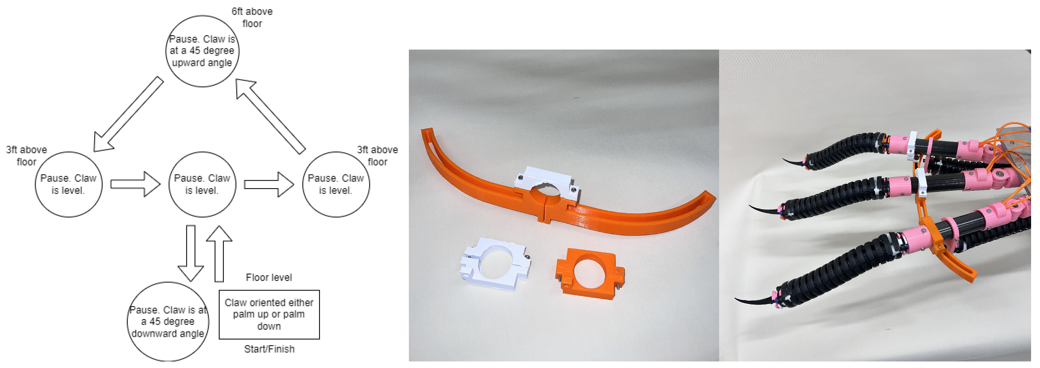
3.1. Range of Motion

In this experiment, we explore the range of motion of the Claw, the results of which are presented visually in Figure 7, Figure 8 and Figure 9. First, as seen in Figure 7, we actuated the gripper to the maximum and minimum spread of the forward facing digits, realizing approximately 30 of adduction and 30 of abduction from the baseline configuration. This means the overall angle between the outer digits reaches approximately 120 (referred to as the divarication angle in ornithology), which encompasses the full range of divarication angles reported in anisodactyl morphotypes and approaches the upper limit of the same measurement reported in raptorial morphotypes [39]. When fully spread, the distance between the end points of the outermost digits measured approximately 1.1 m.
Next, as with the abduction/adduction motion, we tested the range of flexion and extension provided by the distal continuum section at the end of each digit. As seen in Figure 8, the distal sections achieved approximately 120 of flexion. The extension of the distal sections proved capable of straightening the continuum sections against the effects of gravity and internal loads. We did not attempt to extend the fingers upward past the natural capabilities of biological anatomy, but this range of motion is available to the gripper.
Finally, we demonstrate the full sweep of the thumb as actuated by the DC motor and worm gear. As seen in Figure 9, the thumb has approximately 150 of travel. The total length of the gripper when the thumb was fully rearward facing measured approximately 1 m.

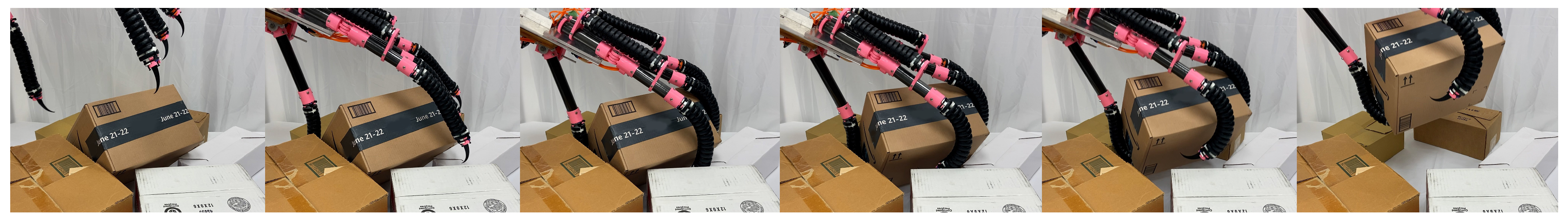
3.2. Grasping Capability

The Claw has a calculated maximum grasping force of 5.32 N when the outside appendages are held at a 30 degree angle, which is considered baseline for The Claw. 30 degrees was chosen for the calculation as it is the center point between abduction and adduction engagement threshold. Additionally, The Claw’s position in all of the following experiments in Section 3.2 and Section 3.3 is controlled by a human user, where it was lifted and maneuvered using a long shaft extending from the base of the Claw. A stand was also built to assist in supporting the Claw during static experiments and the grasping strength tests.
The next reported experiment involved a series of qualitative examples of the Claw’s ability to perform as a gripper. We demonstrated this by picking up a variety of objects and observing how the Claw responded to the different shapes, textures, and structures. We first conducted experiments to grasp a pair of soft, shaped objects, namely a standard book bag (1.3 kg, 0.52 m × 0.17 m × 0.33 m) and a series of toy stuffed animals, as shown in Figure 10 and Figure 11, respectively. Both the book bag and the stuffed animals have sufficient rigidity to retain their respective shapes while being handled by the Claw, resulting in successful grasps. The compliance of the book bag allows the Claw to squeeze the bag and the stiffness of the fabric keeps the bag from being able to slide out between the digits as the bag’s shape is slightly changed. It can be observed that in the case of the stuffed animal, the Claw exhibits a pinch like grasp, where the talons and the tips of the digits appeared to be the main contact points with the stuffed animal. The scale and compliance of the Claw’s structure are the enabling factors for this ability, which would be difficult to replicate on a soft object of this size without a compliant gripper.
Next, we attempted to grasp a large spring loaded collapsible tunnel, which measured 0.46 m in diameter, 0.86 m in length, and weighed 1.13 kg. We initially approached the tunnel in a similar sequence to the stuffed animal, with the “palm” of the gripper facing downward, attempting to partially encircle the tunnel with the continuum sections while executing a power grasp with the rigid segments. This resulted with the tunnel either slipping through the continuum sections or rotating about the thumb and falling from the open sides of the gripper. To combat the tendency of the tunnel to rotate about the thumb and its exploitation of the relative weakness of the continuum sections, we then attempted the sequence shown in Figure 12, in which we turned the palm upward to support and balance the tunnel across the three forward facing digits and used the thumb to hold the tunnel in place. As can be seen, this resulted in the Claw successfully grabbing the tunnel from the surface. In executing this maneuver, we did find it necessary to initially place a piece of aluminum extrusion (clearly seen in the right most image) against the tunnel to prevent it from rolling away while we attempted the grasp. The grasping of the tunnel also led to the detachment of one of the removable talons, seen left sitting on the table in the right most image, which was easily popped back into place.
In another experiment, we attempted to pick up one of the boxes on a cluttered surface, arranged to create the potential for the box to shift or fall during the grasping process. This experiment highlights the usefulness of the continuum sections in conforming and encapsulating an object regardless of changes in orientation during manipulation. The successful sequence can be seen in Figure 13.

3.3. Static and Dynamic Load Assessment

We then tested the Claw to determine how much weight it could support before failure, i.e., a break or drop occurs. A static load test was performed by having the Claw grip a cardboard container of negligible mass and slowly adding weight in 0.44 kg increments. Two orientations were tested, where the first one was with the “palm” of the Claw facing downward and the second one with the “palm” facing upward, as depicted on the left and right of Figure 14, respectively. When the Claw was oriented “palm” down, it was able to hold between 1.8 kg and 4.5 kg before the load fell from the Claw’s grasp. The high variance in the point of failure appeared to dependent on the initial grip quality that the Claw had on the container and the distribution of the load as it balanced on the thumb. As weight was added to the box, the balancing point would shift. This resulted in the box tipping over the side of the thumb, or being pushed down onto the continuum section which will begin to deflect heavily once over a weight threshold. The strength of individual appendages can be seen in Table 2. When the Claw was oriented with the “palm” facing upward, it was able to support 4.5 kg with little to no sign of strain, even after supporting the load for an extended period of time (>20 min). In this case, it was clear that the load was able to rest and balance against multiple digits, providing a seemingly more robust grasp.
In addition to testing the hand’s static load capabilities, we assessed the capabilities of the motor driving the thumb while traveling between open and closed positions, individual digit strength, and the maximum load sustainable while moving through a defined path in space. To test strength of the motor driving the thumb, we suspended increasing amounts of mass from the end of the rigid segment of the thumb (at the base of the continuum section) and moved the thumb forward and back until the strain of the mass appeared to stall or nearly stall the motor. This maximum dynamic load was found to be approximately 1.5 kg.
To determine the maximum strength of individual digits, varying weights (seven weights increasing from 0.05 kg to 0.35 kg by 0.05 kg increments) were hung from the rigid end of the digit, just before the plastic claw inserts. The digits started in the gripped position at 40 psi, with the “palm” facing upward. The starting height was kept constant between trials of the same weight to consistently measure the digit’s sag. Each weight was tested 3 times for each digit, for a total of 21 trials for each of the four digits, with the results for each weight averaged for a given digit. Failure point was deemed as a 50% drop from the starting height.
The results, shown in Table 2, display the percentage of the total height that the digit sagged under the tested weight. Individual digits were able to support 0.3 kg without failing, and all tests failed at 0.35 kg, thus their exclusion from the table. Individual digits showed varying drop percentages, with the middle forward-facing digit showing a drop percentage 20% lower compared to the other digits at 0.3 kg.
We conducted further testing to investigate the ability of the Claw to stably grasp objects while moving. Objects chosen for this test were restricted to non-conforming objects which traditional grippers may struggle to maintain or engage with. The objects used in the test, along with their size and weight, are listed in Table 3, while images of the objects can be seen in Figure 15. To fairly test the grasping ability on each object, the Claw was moved in a determined path with consistent speed, with each object tested in “palm” up and “palm” down orientations, simulating both scooping and pinching the object, where the path is defined in the left-most image of Figure 16.
The foam and the soft tool were tested at their empty weights, and also at added mass intervals of 0.44 kg, 0.88 kg, and 1.32 kg. Each object was experimented 3 times through the path in both Claw orientations. The results of the dynamic tests can be found in Table 4, where a “P” represents the object completing the movement without falling out, and “F” representing the object falling out at some point during the movement. For the “palm” up tests, failures were mostly attributed to object being able to slide backwards into the thumb, becoming unsettled that resulted in object slipping out as movement progressed. The “palm” down failures were attributed to the continuum section of the thumb deflecting under heavy load allowing the object to slip down and out of the object, most notably at the −45° angle. Ultimately, the initial quality of the grip was the greatest determinate in whether or not an object would pass the dynamic test.
One issue that came to light during dynamic testing was a weakness regarding the adduction and abduction muscles. Pressure was only applied to the muscles when under adduction or abduction, and once maximum or minimum spread was achieved, only then was there enough pressure in the muscles to maintain their positions. This results in the outside appendages shifting left and right as the Claw is moved around if the muscles are in any positions except the maximum or minimum spread. To counteract this undesired movement, a brace (center and right-most of Figure 16) was created to help support the adduction and abduction muscles so there would be less sway in the appendages.
A Supplementary Video S1 showing some of the above described experiments is included.

4. Discussion

When observing the individual elements of the Claw, namely the rigid versus the continuum segments, there are a number of disadvantages that would make either element a poor universal gripper. The continuum sections are useful for compliant grasping and adapting to various object geometries, but the sections are not very strong and can be manipulated and pushed into different directions by external forces. Conversely, the rigid elements exhibit relatively high strength and the ability to support external loads, but also lack the ability to conform to environmental objects. In light of these individual shortcomings, it was a key premise of the Claw to explore how rigid and continuum joints can be combined to make a better gripper.
One clear advantage of the hybrid rigid-continuum nature, at least from the perspective of continuum robots, was displayed during the static load test. The strength of the rigid sections provided stability for the applied load while the continuum sections constrained the objects from shifting in an unstable manner. Likewise, throughout the grasping experiments, we observed the nature of the continuum sections to encircle and secure loads while the rigid segments supported loads and solid anchors for the continuum sections.
In considering our restriction of the middle forward-facing digit from participating in the abductive/adductive movement, we initially chose to reduce the number of regulators necessary to actuate the system in applying this constraint. In the abduction/adduction of the outer digits, it is possible to achieve the desired motion by mirroring the inputs to the digits, using only two regulators to drive both outer digits toward and away from the middle digit. In actuating the middle digit in this manner, it would be necessary to chose a priori which direction the digit would move in, or to provide two independent inputs for this digit alone. This would result in more complex hardware without a clear advantage or inspiration from avian foot anatomy.
One way we might relax the restriction of the middle digit in future work would be to explore adding webbing between the digits. Webbing could allow the Claw to grasp more abnormally shaped objects and prevent the objects from sliding out between the digits. It would likewise allow the middle digit to move naturally towards either of the outer digits without leaving a large gap that might allow for a grasped object to escape.
Other material alterations to explore in future work include adding padding to the digits, similar to that which raptor anatomy exhibits. Padding could help prevent objects from sliding out by increasing friction between objects and the digits of the Claw. In order to aid in the grasping of larger, more irregular objects, we could also explore including additional continuum or rigid sections, much like the addition of extra phalanges in an appendage.
Other modifications that could be made in the future include consideration of alternative methods of construction for the revolute thumb joint. The existing joint has some play within it, so that the digits bend slightly more than desired under high loading conditions, generally dependent on where an object is situated in the grasp. The joints are currently reinforced with super glue, but alternative methods of connecting the joints that is stronger and easier to assemble are desirable.
Adding more and different variations of sensing could also improve the Claw. Environment, contact, and shape sensing would increase the usefulness by allowing the Claw to sense when it is touching an object and also what the shape of the object is. This would also help with navigation in cluttered environments if visibility from a (teleoperating) user’s perspective is low or when the Claw is being operated autonomously.

5. Conclusions

We have introduced an adaptive gripper constructed from a combination of rigid and compliant continuum elements. The four-digit gripper, inspired by the feet of raptors, is of relatively large size, and designed for unusually large scale operations suitable for manipulating payloads such as luggage. The combination of rigid and continuum components enable novel modes of grasping and manipulation, trading off the adaptability of the continuum elements with the structural rigidity of the rigid ones. Experiments with the gripper illustrate its ability to gently but securely grasp objects of a variety of sizes and material properties.

Supplementary Materials

The following supporting information can be downloaded at: https://www.mdpi.com/article/10.3390/robotics13030052/s1.

Author Contributions

Conceptualization, I.D.W. and C.G.F.; methodology, M.E.S., J.K.M. and C.G.F.; hardware development, M.E.S. and C.G.F.; validation, J.K.M., M.E.S. and C.G.F.; resources, I.D.W. and G.L.; writing—original draft preparation, C.G.F., I.D.W. and M.E.S.; writing—review and editing, J.K.M., I.D.W. and G.L.; project administration, I.D.W. and G.L. All authors have read and agreed to the published version of the manuscript.

Funding

This research was supported by the U.S. National Science Foundation under grants 1924721 and 1718075, by NASA Space Technology Research Fellowship contract 80NSSC17K0173, by a Clemson Honors College Departmental Research grant, and by a Clemson University CECAS Research Opportunity grant.

Data Availability Statement

The original contributions presented in the study are included in the article, further inquiries can be directed to the corresponding author.

Conflicts of Interest

The authors declare no conflict of interest.

References

  1. Kato, I. Mechanical Hands Illustrated; Survey Japan; Intl Specialized Book Services: Portland, OR, USA, 1982. [Google Scholar]
  2. Bicchi, A. Hands for dexterous manipulation and robust grasping: A difficult road toward simplicity. IEEE Trans. Robot. Autom. 2000, 16, 652–662. [Google Scholar] [CrossRef]
  3. Melo, G.; Nathalia, E.; Sanchez, A.; Fernando, O.; Hurtado, A. Anthropomorphic robotic hands: A review. Ing. Desarro. 2014, 32, 279–313. [Google Scholar]
  4. Melchiorri, C.; Kaneko, M. Robot Hands. In Proceedings of the Springer Handbook of Robotics, 2nd ed.; Siciliano, B., Khatib, O., Eds.; Springer: Berlin/Heidelberg, Germany, 2016; Chapter 19; pp. 463–480. [Google Scholar]
  5. Beddow, L.; Wurdemann, H.; Kanoulas, D. A Caging Inspired Gripper using Flexible Fingers and a Movable Palm. In Proceedings of the IEEE/RSJ International Conference on Intelligent Robots and Systems (IROS), Prague, Czech Republic, 27 September–1 October 2021; pp. 7195–7200. [Google Scholar]
  6. Liu, Y.; Bi, Q.; Li, Y. Development of a Bio-inspired Soft Robotic Gripper based on Tensegrity Structures. In Proceedings of the IEEE/RSJ International Conference on Intelligent Robots and Systems (IROS), Prague, Czech Republic, 27 September–1 October 2021; pp. 7398–7403. [Google Scholar]
  7. Liu, C.; Wohlever, S.; Ou, M.; Padir, T.; Felton, S. Shake and Take: Fast Transformation of an Origami Gripper. IEEE Trans. Robot. 2022, 38, 491–506. [Google Scholar] [CrossRef]
  8. Hughes, J.; Culha, U.; Giardina, F.; Guenther, F.; Rosendo, A.; Iida, F. Soft Manipulators and Grippers: A Review. Front. Robot. AI 2016, 3, 69. [Google Scholar] [CrossRef]
  9. Ho, V.; Hirai, S. Design and Analysis of a Soft-Fingered Hand with Contact Feedback. IEEE Robot. Autom. Lett. 2017, 2, 491–498. [Google Scholar] [CrossRef]
  10. Galloway, K.; Becker, K.; Phillips, B.; Kirby, J.; Licht, S.; Tchernov, D.; Wood, R.; Gruber, D. Soft Robotic Grippers for Biological Sampling on Deep Reefs. Soft Robot. 2016, 3, 23–33. [Google Scholar] [CrossRef]
  11. Sinatra, N.; Teeple, C.; Vogt, D.; Parker, K.; Gruber, D.; Wood, R. Ultragentle Manipulation of Delicate Structures Using a Soft Robot Gripper. Sci. Robot. 2019, 4, 1–11. [Google Scholar] [CrossRef]
  12. Townsend, W. The BarrettHand grasper–programmably flexible part handling and assembly. Ind. Robot. Int. J. 2000, 27, 181–188. [Google Scholar] [CrossRef]
  13. Walker, I.; Dawson, D.; Flash, T.; Grasso, F.; Hanlon, R.; Hochner, B.; Kier, W.; Pagano, C.; Rahn, C.; Zhang, Q. Continuum Robot Arms Inspired by Cephalopods. In Proceedings of the SPIE Conference Unmanned Ground Vehicle Technology, Orlando, FL, USA, 29–31 March 2005; pp. 303–314. [Google Scholar]
  14. Li, J.; Xiao, J. Determining “Grasping” Configurations for a Spatial Continuum Manipulator. In Proceedings of the IEEE/RSJ International Conference on Intelligent Robots and Systems (IROS), San Francisco, CA, USA, 25–30 September 2011; pp. 4207–4214. [Google Scholar]
  15. Li, J.; Teng, Z.; Xiao, J.; Kapadia, A.; Bartow, A.; Walker, I. Autonomous Continuum Grasping. In Proceedings of the IEEE/RSJ International Conference on Intelligent Robots and Systems (IROS), Tokyo, Japan, 3–7 November 2013; pp. 4569–4576. [Google Scholar]
  16. Lane, D.; Davies, J.; Robinson, G.; O’Brien, D.; Sneddon, J.; Seaton, E.; Elfstrom, A. The AMADEUS Dextrous Subsea Hand: Design, Modeling, and Sensor Processing. IEEE J. Ocean. Eng. 1999, 24, 96–111. [Google Scholar] [CrossRef]
  17. Piazza, C.; Grioli, G.; Catalano, M.; Bicchi, A. A Century of Robotic Hands. Annu. Rev. Control. Robot. Auton. Syst. 2019, 2, 1–32. [Google Scholar] [CrossRef]
  18. Subad, R.; Cross, L.; Park, K. Soft Robotic Hands and Tactile Sensors for Underwater Robotics. Appl. Mech. 2021, 2, 356–382. [Google Scholar] [CrossRef]
  19. Zhao, W.; Zhang, Y.; Wang, N. Soft Robotics: Research, Challenges, and Prospects. J. Robot. Mechatronics 2021, 33, 45–68. [Google Scholar] [CrossRef]
  20. Cerruti, G.; Chablat, D.; Gouaillier, D.; Sakka, S. ALPHA: A hybrid self-adaptable hand for a social humanoid robot. In Proceedings of the IEEE/RSJ International Conference on Intelligent Robots and Systems, Daejeon, Republic of Korea, 9–14 October 2016. [Google Scholar]
  21. Li, Y.; Cong, M.; Liu, D.; Du, Y. A Practical Model of Hybrid Robotic Hands for Grasping Applications. J. Intell. Robot. Syst. 2022, 105, 1–15. [Google Scholar] [CrossRef]
  22. Nguyen, P.; Bui, T.; Ho, V. Towards Safely Grasping Group Objects by Hybrid Robot Hand. In Proceedings of the 4th International Conference on Robotics, Control and Automation Engineering, Wuhan, China, 16–18 November 2021; pp. 389–393. [Google Scholar]
  23. Ramos, A.; Walker, I. Raptors: Inroads into Multifingered Grasping. In Proceedings of the IEEE/RSJ International Conference on Intelligent Robots and Systems (IROS), Victoria, BC, Canada, 13–17 October 1998; pp. 467–475. [Google Scholar]
  24. Nabi, F.; Sundaraj, K.; Vijean, V.; Shafiq, M.; Planiappan, R.; Talib, I.; Rehman, H. A Novel Design of Robotic hand Based on Bird Claw Model. J. Phys. Conf. Ser. 2021, 1997, 012034. [Google Scholar] [CrossRef]
  25. Backus, S.; Odhner, L.; Dollar, A.M. Design of hands for aerial manipulation: Actuator number and routing for grasping and perching. In Proceedings of the IEEE/RSJ International Conference on Intelligent Robots and Systems (IROS), Chicago, IL, USA, 14–18 September 2014; p. 40. [Google Scholar]
  26. Doyle, C.; Bird, J.; Isom, T.; Johnson, C.; Kallman, J.; Simpson, J.; King, R.; Abbott, J.; Minor, M. Avian-inspired passive perching mechanism for robotic rotorcraft. In Proceedings of the IEEE/RSJ International Conference on Intelligent Robots and Systems (IROS), San Francisco, CA, USA, 25–30 September 2011; pp. 4975–4980. [Google Scholar]
  27. Roderick, W.; Cutkosky, M.; Lentink, D. Bird-inspired Dynamic Grasping and Perching in Arboreal Environments. Sci. Robot. 2021, 6, eabj7562. [Google Scholar] [CrossRef]
  28. McLaren, A.; Fitzgerald, Z.; Gao, G.; Liarokapis, M. A Passive Closing, Tendon Driven, Adaptive Robot Hand for Ultra-Fast, Aerial Grasping and Perching. In Proceedings of the IEEE International Conference on Intelligent Robots and Systems (IROS), Venetian Macao, Macau, 3–8 November 2019; pp. 5602–5607. [Google Scholar]
  29. Thomas, J.; Polin, J.; Sreenath, K.; Kumar, V. Avian-inspired grasping for quadrotor micro uavs. In Proceedings of the ASME International Design Engineering Technical Conferences and Computers and Information in Engineering Conference, Portland, OR, USA, 4–7 August 2013; p. V06AT07A014. [Google Scholar]
  30. Xu, F.; Wang, B.; Shen, J.; Hu, J.; Jiang, G. Design and Realization of the Claw Gripper System of a Climbing Robot. J. Intell. Robot. Syst. 2015, 89, 301–317. [Google Scholar] [CrossRef]
  31. Xu, J.; Xu, Q. Design of an engineering bionic flexible mechanical claw. J. Phys. Conf. Ser. 2021, 1865, 032051. [Google Scholar] [CrossRef]
  32. Quigley, M.; Salisbury, C.; Ng, A.; Salisbury, J. Mechatronic design of an integrated robotic hand. Int. J. Robot. Res. 2014, 33, 706–720. [Google Scholar] [CrossRef]
  33. Jacobsen, S.; Iversen, E.; Knutti, D.; Johnson, R.; Biggers, K. Design of the Utah/MIT dextrous hand. In Proceedings of the 1986 IEEE International Conference on Robotics and Automation IEEE, San Francisco, CA, USA, 7–10 April 1986; Volume 3, pp. 1520–1532. [Google Scholar]
  34. Lovchik, C.; Diftler, M. The robonaut hand: A dexterous robot hand for space. In Proceedings of the 1999 IEEE International Conference on Robotics and Automation (Cat. No. 99CH36288C) IEEE, Detroit, MI, USA, 10–15 May 1999; Volume 2, pp. 907–912. [Google Scholar]
  35. Kochan, A. Shadow delivers first hand. Ind. Robot. Int. J. 2005, 32, 15–16. [Google Scholar] [CrossRef]
  36. Mykhailyshyn, R.; Savkiv, V.; Maruschak, P.; Xiao, J. A systematic review on pneumatic gripping devices for industrial robots. Transport 2022, 37, 201–231. [Google Scholar] [CrossRef]
  37. Vertongen, J.; Kamper, D.; Smit, G.; Vallery, H. Mechanical Aspects of Robot Hands, Active Hand Orthoses, and Prostheses: A Comparative Review. IEEE/ASME Trans. Mechatronics 2020, 26, 955–965. [Google Scholar] [CrossRef]
  38. Calli, B.; Singh, A.; Walsman, A.; Srinivasa, S.; Abbeel, P.; Dollar, A. The ycb object and model set: Towards common benchmarks for manipulation research. In Proceedings of the 2015 International Conference on Advanced Robotics (ICAR), IEEE, Istanbul, Turkey, 27–31 July 2015; pp. 510–517. [Google Scholar]
  39. Tsang, L.R.; McDonald, P.G. A comparative study of avian pes morphotypes, and the functional implications of Australian raptor pedal flexibility. Emu-Austral. Ornithol. 2019, 119, 14–23. [Google Scholar] [CrossRef]
  40. Fowler, D.W.; Freedman, E.A.; Scannella, J.B. Predatory functional morphology in raptors: Interdigital variation in talon size is related to prey restraint and immobilisation technique. PLoS ONE 2009, 4, e7999. [Google Scholar] [CrossRef] [PubMed]
  41. Arachchige, D.D.; Chen, Y.; Walker, I.D.; Godage, I.S. A novel variable stiffness soft robotic gripper. In Proceedings of the 2021 IEEE 17th International Conference on Automation Science and Engineering (CASE), Lyon, France, 23–27 August 2021; pp. 2222–2227. [Google Scholar]
Figure 1. Biologically inspired by avian hind limb anatomy, e.g., Goshawk [40] (top). The Claw (bottom) is a large scale hybrid rigid-continuum gripper with topology arranged in a similar fashion. Note: the Goshawk hind limb is approximately human hand size, and the Claw is much larger.
Robotics 13 00052 g001
Figure 2. The Claw, a hybrid rigid-continuum gripper, features three forward-facing digits (a) and one backward facing digit (b). The digits have rigid proximal structures, with their distal tips compliant pneumatically actuated continuum elements. The backward facing digit (b) has its proximal rigid element directly actuated by a motor. The digits (a) are coupled in abduction/adduction (perpendicular to plane of image) by additional compliant continuum elements.
Robotics 13 00052 g002
Figure 3. Assembly of elements for single outer Claw digit. Not pictured: an optional talon added at the end of the distal continuum section. Note the combination of rigid rod elements and compliant continuum components.
Robotics 13 00052 g003
Figure 4. The three muscles comprising each of the utilized continuum sections can be paired to mimic planar, antagonistic muscle groups. The designated areas are the terminal points of the various McKibben muscles contained within the continuum sections. Differentially pressurizing the sets of muscle groups provides the actuation forces used to bend the structures.
Robotics 13 00052 g004
Figure 5. Sub-assembly of the backward facing digit, featuring a worm gear. This digit is driven by the pictured DC motor.
Robotics 13 00052 g005
Figure 6. Claw system diagram. A remote compressor provides the pneumatic pressure supply for the compliant continuum elements. The desired pressure input for each individual muscle is calculated on an Arduino Mega, and regulated with individual pressure regulators. The regulators receive voltage input from the Arduino via the DAC, and use an internal feedback loop to regulate the actuators to the corresponding pressure.
Robotics 13 00052 g006
Figure 7. From the baseline, the Claw has approximately 30 of abduction (red) and 30 of adduction (blue). Both abduction and adduction are actuated purely using pneumatic sources.
Robotics 13 00052 g007
Figure 8. Both forward and backward facing digits are capable of approximately 120 of flexion. The degree of flexion varies with input pressure and contact with objects. Note that both electric (DC motor) and pneumatic actuation are used for (only) the backward facing digit.
Robotics 13 00052 g008
Figure 9. The thumb (backward facing digit) is capable of 150 of travel and dynamic loads of 1.5 kg.
Robotics 13 00052 g009
Figure 10. Grasping of a standard book bag (left) and a toy stuffed rabbit (right), length: 0.56 m, width: 0.2 m, weight: 0.39 kg.
Robotics 13 00052 g010
Figure 11. Demonstrating pinch grasp of a soft, conformable toy stuffed animal length: 0.62 m, width: 0.18 m, weight: 0.33 kg (0.12 m approximate grasp across toy’s midriff). Image evenly spaced for 12 s.
Robotics 13 00052 g011
Figure 12. Grabbing of a compliant, 0.45 m diameter collapsible tunnel. Image evenly spaced for 21 s.
Robotics 13 00052 g012
Figure 13. Grabbing of a box dimension: 0.38 × 0.38 × 0.15 m, weight: 0.28 kg, in a cluttered, unstable workspace. Image evenly spaced for 15 s.
Robotics 13 00052 g013
Figure 14. Static load test of the Claw in downward facing (left) and upward facing orientation (right). Mass in the container was incrementally increased (discrete 0.44 kg intervals) until the mass caused the object to slip from the Claw’s grasp.
Robotics 13 00052 g014
Figure 15. From left to right: scoop grasp of soft tool bag and cable bundle, and pinch grasp of a soft ball and foam padding.
Robotics 13 00052 g015
Figure 16. (Left) Diagram of path used for testing maximum sustainable load (starting with “Pause. Claw is level” as indicated in the center). (Center) Brace designed to constrain Abduction and Adduction Muscle sway when the Claw is moving or rotating. (Right) Claw with the brace implemented.
Robotics 13 00052 g016
Table 1. Physical and operational specifications of the Claw.
Specifications of the Claw
Dimensions (m)Operating Pressure (kpa)Open/Close Speed (m/s)Weight (kg)
Length: 0.24 (base-mid digit tip)Open/Close: 0–276Thumb: 0.25/0.334.92
Width: 0.72 (full abduction)Abduction/Adduction: 0–207Digits: 0.27/0.27N/A
Table 2. Results from testing maximum strength of individual digits. These results were adjusted due to differences in total height between trials of different weight. As an example, 4.19 represents Front Digit 1’s average drop, over three trials, as a percentage of total height with 0.05 kg of weight.
Adjusted Drop Percentage (as a Percentage of Total Height Measured from Surface)
Weight [g]Front Digit 1Front Digit 2Front Digit 3Rear Digit
504.192.534.243.46
1008.565.468.376.93
15015.648.9114.7614.71
20022.0214.5620.3625.40
25033.6324.0833.1435.21
30047.8337.2146.3744.90
Table 3. Characteristics of items used in the dynamic testing of grasping non-conforming objects.
ObjectSizeMass
Soft tool bag1.79 × 10 2 m 3 0.46 kg
Wire bundle0.31 m diameter1.49 kg
Soft ball0.25 m diameter0.16 kg
Foam padding6.56 × 10 3 m 3 6.5 × 10 2 kg
Table 4. Results of dynamic testing of grasping of non-conforming objects. Each object was tested 3 times in both palm up and palm down orientations. The letter “P” and “F” represent a pass and a fail, respectively.
ObjectPalm up TestsPalm down Tests
BallP P PF P P
BunnyP P PP F F
Wire BundleP P PF F F
Soft Tool bag (empty)P P PP P P
Soft Tool bag (0.44 kg)P F FP P P
Soft Tool bag (0.88 kg)F F FP F P
Soft Tool bag (1.32 kg)F F FF F F
Foam Padding (empty)P P PP P P
Foam Padding (0.44 kg)P P PP P P
Foam Padding (0.88 kg)P P PP P P
Foam Padding (1.32 kg)P P PF F F
Disclaimer/Publisher’s Note: The statements, opinions and data contained in all publications are solely those of the individual author(s) and contributor(s) and not of MDPI and/or the editor(s). MDPI and/or the editor(s) disclaim responsibility for any injury to people or property resulting from any ideas, methods, instructions or products referred to in the content.

