Article

Sensor-Based Trajectory Generation for Advanced Driver Assistance System

by
Christopher James Shackleton
,
Rahul Kala
and
Kevin Warwick
*
School of Systems Engineering, University of Reading, Whiteknights, Reading, Berkshire, RG6 6AY, UK
*
Author to whom correspondence should be addressed.
Robotics 2013, 2(1), 19-35; https://doi.org/10.3390/robotics2010019
Submission received: 11 January 2013 / Revised: 19 February 2013 / Accepted: 5 March 2013 / Published: 11 March 2013
(This article belongs to the Special Issue Human Centred Robotics)

Abstract

:
This paper investigates the trajectory generation problem for an advanced driver assistance system that could sense the driving state of the vehicle, so that a collision free trajectory can be generated safely. Specifically, the problem of trajectory generation is solved for the safety assessment of the driving state and to manipulate the vehicle in order to avoid any possible collisions. The vehicle senses the environment so as to obtain information about other vehicles and static obstacles ahead. Vehicles may share the perception of the environment via an inter-vehicle communication system. The planning algorithm is based on a visibility graph. A lateral repulsive potential is applied to adaptively maintain a trade-off between the trajectory length and vehicle clearance, which is the greatest problem associated with visibility graphs. As opposed to adaptive roadmap approaches, the algorithm exploits the structured nature of the environment for construction of the roadmap. Furthermore, the mostly organized nature of traffic systems is exploited to obtain orientation invariance, which is another limitation of both visibility graphs and adaptive roadmaps. Simulation results show that the algorithm can successfully solve the problem for a variety of commonly found scenarios.

1. Introduction

Advanced Driver Assistance Systems (ADASs) [1] are seen to be the bridge between the current, driver oriented automotive design and future autonomous vehicle design. ADASs come in a variety of formats, from pedestrian detection [2], to lane keeping assistance/lane departure warning [3]. These systems are in place to reduce the amount that human drivers have to do in order to control a vehicle; this is a particularly necessary task, as 34,826 road casualties occurred in 2009 within the European Union [4]. The same reference shows that personal cars and taxis account for the largest percentage of these, in total 48.88%, with pedestrians in second, marking pedestrian detection and avoidance systems as a necessity for future vehicles. However, in order for these systems to function, sensors must be employed for the collection of information, which can then be used as inputs to trajectory planning algorithms. The interconnection of these advanced driver assistance systems is what is likely to lead to the first commercially available autonomous vehicle.
ADAS make an interesting example of human centric computing, wherein technology is used to assist humans [5]. The aim of ADAS is to use intelligent devices to aid in the decision making of human drivers. The chief motivation is to make vehicles secure and avoid any possible collision, even if the human makes errors. An important aspect of these systems is hence to enable technology to work hand-in-hand with a human operator, wherein any information should be presented in a manner acceptable to the human, while any decisions or actions of the assistance system should be in consensus with the human driver’s preferences. Lack of consensus or lack of trust between the human and the assistance system can be a severe threat.
ADAS may be information-based or manipulation-based. Information based systems use intelligent sensors and data processing to provide information to the user useful for his/her driving. Manipulation based systems, in turn, use sensor and vision information to actually control the car in scenarios that seem to be dangerous. The human, on the other hand, may still be required for general driving, depending upon his/her preferences. Manipulation-based systems are harder to design, as they have additional considerations of when, what and how much assistance is to be given—they are, however, safer. In real life, a safe state may become dangerous in a split second, owing to a poor driving decision or a large reaction time to changes in the environment. Information-based systems warn the driver, allowing them to take the necessary safety measures. Considering high operating speeds, the time spent by a human in perceiving the warning sign, interpreting it and deciding on the preventative action may be too large [6]. Assistance systems can, however, take precautionary actions well in time, as well as prepare to reduce the effects on a driver should a crash occur [7]. It should be remembered, however, that false positives in sensing provide additional concerns [8].

1.1. Sensing

The first important task in an ADAS is sensing, wherein the vehicle perceives the other vehicles and static obstacles around. The sensing results in a local map of the environment, which is used for further processing. Sensors, such as radar, LIDaR, ultrasonics and cameras are used within the automotive industry to provide information to a vehicle’s control systems about its surroundings. It is these sensors that are used for the ADAS systems. In this case, many, multiple sensors are used at once for the same task in order to verify information [9] or to make measurements where the primary sensing modality fails [10]. This is known as sensor fusion. Benefits and problems with the interconnection of systems are highlighted in Darms and Winners’ work [11], where some applications of sensors are also highlighted.
Many sensors operating at boundaries can prevent systems from working correctly in particular environments, and therefore, this restricts the use of that particular sensor as a solution to a problem. This is evident in the case of Automatic Cruise Control (ACC) in which it is possible to implement camera-based systems; however, most commercially available ACC units operate using radar. This is due to the fact that radar is unaffected by lighting conditions and weather, whilst still having sufficient range. The sensor also satisfies the requirements for following a vehicle at speed. Cameras, however, may be ideal for multi-object tracking ACC.
Typically, sensors within an automotive application are required to be low cost, as well as reliable. The most common sensor found on entry-level vehicles is the ultrasonic parking aid, of which many variants exist. The range for this particular sensor is relatively small, at approximately 4 m, which may be ideal for close following applications; however, it may be necessary to measure larger distances, in which case a camera (up to 40 m range), LIDaR or radar (both 150 m range) may be appropriate.
A modern perspective is to use inter-vehicle communication [12,13] between intelligent vehicles. When operating in a grid of mixed traffic consisting of both intelligent vehicles and non-intelligent vehicles, the intelligent vehicles can transmit information about other vehicles or obstacles. This enables limited sensing capability vehicles to obtain information about the traffic ahead and vehicles to “see” beyond their vision range. On top of this, collaborative data checking can refine vehicle sensing errors.

1.2. Trajectory Generation and Assistance

Given a map, the aim of trajectory generation is to construct a short, safe and smooth trajectory. Safety not only accounts for the fact that no collision should occur, but also makes the vehicle maintain the correct safety distance. The safety distance covers for any sensing and actuation errors that may appear. Further, this is in consensus with human driving, wherein drivers prefer to maintain wide gaps between themselves and vehicles all around. Important considerations in the choice of trajectory planning algorithms are completeness, optimality and computation time. Reactive planning techniques (e.g., [14]) assess the immediate scenario and compute the immediate move. Such techniques may well have small computation times; however, they are almost always neither complete nor optimal. Hence, deliberative techniques (e.g., [15]) are preferred, which, at the expense of computation time, are better in completeness and optimality.
The environment may be structured or non-structured. When planning in a structured environment, it is assumed that the complete environment is known, with the different obstacles depicted as polygons or circles with known sizes. This is naturally true in the case of traffic scenarios, with other vehicles being mostly rectangular, whose geometry can be sensed. Search techniques then fit a lot of applications, as they assure both optimality and completeness. A structured environment can be easily converted into a graph (or similar structure) with a limited number of nodes for fast planning, although search-based planning in an unstructured environment would be too computationally expensive. Typical approaches include Voronoi maps [16], velocity obstacles [17] and visibility graphs [18,19].
Unlike mainstream mobile robotics, the aim is not to make the vehicle physically move by a computed trajectory, since the human may have a different plan in mind. Instead, the aim is to assess the vehicle’s safety state, depending upon which it is decided whether the assistance system should intervene in the human driving to correct his/her trajectory and, if so, by what magnitude. Should evasive action need to be taken, this could be conveyed to the driver by means of a force feedback steering wheel, as used in [20,21]; interestingly, acceleration reduction can also be conveyed to the driver in a similar way [22].

1.3. Proposed Solution and Main Contributions

This paper deals with the design of an assistance system that ensures user safety and takes preventative steps for the same. The algorithm assumes that a map produced by sensors and in cooperation with the other vehicles is already available. The map is used for generation of the trajectory, which is the chief part of the problem tackled in this paper. The constructed trajectory is then used for deciding the control action to be applied based on the assessed risk. Due to the current constraints, the sensing and manipulation aspects of the assistance system cannot be physically implemented and tested; they are for motivation only.
The developed solution is a hybrid of visibility graphs [18,19] and adaptive roadmaps [23,24,25,26]. The visibility graphs are well-suited for structured environments for which they perform fast and effective planning. The general idea is to place graph nodes across the obstacle points. The nodes are then assessed for connectivity to produce a graph, which is used for planning. The biggest problem with this approach is the assumption of a structured environment, as well as the ability to control the trade-off between the trajectory length and clearance. Clearance denotes the (more than minimal) safety distance available to the vehicle. The assumption of a structured environment is not a bad assumption to make in a traffic scenario. However it is important to intelligently place the vehicles depending upon how much space is available.
Adaptive roadmap based approaches [23,24,25,26] can easily model the potential functions to trade-off between the trajectory length and clearance. Being widely used for mobile robotics, these generally sample out random points from the map, which are later checked for connectivity, and the resultant graph produced is called as a roadmap. The paper uses the potential-based modelling of these approaches applied to a graph based on the visibility graphs. As a result, lesser and more strategically placed nodes are produced.
Orientation is a major factor, which decides the feasibility of a node (and the associated clearance or length of a path) in such a graph or roadmap-based approach. The factor is even more useful in a road scenario in which vehicles are tightly packed on roads instead of having wide open spaces, as in many mobile robotics cases. Hence, it is not possible to focus on diagonal or maximum length for node placement. The paper handles this problem using the mostly organized nature of a general traffic landscape, as compared to that in mobile robotics. For the same reason, the application of the potential for alteration of a visibility graph node is restricted to the lateral direction of the road. Section 3.3 elaborates this point.
The key contributions of the approach are: (i) using a hybrid of potential fields and visibility graphs for trajectory planning, (ii) using heuristics to solve the problem of rotational dependence associated with such techniques in environments with narrow spaces, (iii) interpreting all traffic behaviours and casting them into a visibility graph framework, rather than only using nodes around obstacles and (iv) interpreting the human driver’s driving intentions (through the heading direction) for the problem of trajectory planning, thereby making the system computing trajectory close to the human desired trajectory.
The remainder of this paper is organized as follows: in Section 2, some of the related works are presented. Section 3 describes the problem and goes forward with the modelling of the complete algorithm. Experimental results are given in Section 4, and some concluding remarks are made in Section 5.

2. Related Works

In a recent work, Anderson et al. [27] studied a similar problem. The authors used Delaunay triangles to compute all possible homotopies in a given map. The authors also used Dijkstra’s algorithm for computing the trajectory. The greatest limitation of the approach, however, is that the central points were used for trajectory generation. This means that for scenarios having wide segments between obstacles, the vehicle would drive at the centre, over-compromising its distance to clearance. The proposed algorithm uses the potential function to model the trade-off. Furthermore, the authors did not model the behaviour of a vehicle following another vehicle (as other vehicles were treated as static obstacles), whereas this is considered in the proposed approach.
Our prior work focused on the use of a Rapidly-exploring Random Tress (RRT) Connect [28,29] algorithm for the task of navigation of multiple autonomous vehicles. The vehicles were assumed to be connected via an inter-vehicle communication system, allowing all vehicles to be planned in a prioritized manner. The search was biased towards the areas around the current lateral position of the vehicles. In a related work [30], the problem was solved using RRT. The RRT was sampled using the vehicle’s control model, which ensured that the trajectory generated was safely navigable. The proposed approach is, however, modelled as an ADAS instead of as an autonomous vehicle. RRT and similar approaches can be computationally expensive and, hence, are good models for autonomous driving, where planning frequency is not large. The proposed approach meanwhile assumes the structured nature of the environment for faster planning.
A related problem is decision making in intelligent vehicles. Schubert et al. [31] sensed the vehicles ahead, behind and the distance from the lane markings for decision making regarding lane change. The authors used Bayesian networks for the task. In another approach, Hegeman et al. [32] computed the feasibility of overtaking based on which a human could initiate an overtaking manoeuvre. For the task of construction of the overtaking trajectory, Naranjo et al. [33] developed a fuzzy rule-based system. The system was divided into stages of change to the overtaking lane: complete an overtake and return to the original lane. All these systems perform well when the road is marked with lanes and the entire traffic strictly operates in lanes. In reality, some segments of traffic on some roads may get unorganized, where the vehicles partly slip between lanes. Further, the problem of obstacle avoidance cannot be perfectly solved by lane changes. Hence, generalized planners (like the one proposed) that do not necessarily assume lanes are considered to be better.
Significant work has been done in the domain of mobile robotics for the task of trajectory planning. Gayle et al. [34] used a social potential field to differentiate between types of agents in a multi-agent framework. Using this, along with the general potential field, the authors carried out the planning of agents, which moved under the guidance of an adaptive roadmap [35]. A general graph search cannot be employed for the problem, due to computational constraints. Kala et al. [36] proposed a multi-layer graph search, which made the algorithm iterative and computationally fast. The authors initially carried the graph search on lower resolution maps, and based on the results, the resolution of promising areas was increased. Similar work in the domain of multiple autonomous vehicles can be found in Kala and Warwick [37], which consisted of four layers of hierarchy.
In another approach, the hierarchical D* algorithm was presented by Cagigas and Abascal [38]. The D* algorithm is better suited to a dynamic environment, and its hierarchical nature makes it computationally less intensive. Even though the modifications result in making these approaches computationally less demanding, they cannot be used in such real time systems. Further, it is not possible to hierarchically construct the trajectory of a vehicle, which is a concept suited for open space-like environments. Decisions about overtaking and lane changes are only possible knowing the actual available separations between vehicles and the obstacles. It is not possible to construct a coarser map and make such decisions, as employed in [38].

3. Algorithm

This section talks about the complete design of the assistance system. First, the problem statement is defined, and later, the different segments of the algorithm are discussed.

3.1. Problem Definition

Consider that a vehicle is travelling at a speed v and is currently located at position s with an orientation of Φ. Let the vehicle be a rectangle of length L and width W. A road segment ahead of the vehicle with a length of Ω is considered. It is assumed that the vision algorithms can sense the road ahead and differentiate it from forbidden zones, the zone for vehicles travelling in the opposite direction, pavements, ditches etc. The first task associated with the algorithm is to sense the obstacles and other vehicles around. Consider that the vehicle is fitted with appropriate sensors to sense these or that the vehicles are intelligent and can sense each other (and the obstacles) and share the information.
Hence, let R be the set of vehicles or obstacles, each with a position pi and orientation θi. Since, for a forward travelling vehicle, a collision is only possible with vehicles ahead with smaller speeds, only these are considered. Cases, such as verging, make collisions with vehicles to the side possible. However, such collisions are handled by measuring and tracking side distances and are broadly not dealt with by trajectory-based warning systems. For simplicity, all other vehicles and obstacles are assumed to be rectangles of length li and width wi. Only vehicles and obstacles within the road segment are considered. The only vehicles to be considered are those that the vehicle being controlled looks like it will overtake in the future. These vehicles generally have a lower speed than the vehicle being controlled. The human driver may control his/her speed, so as to clearly indicate the intentions of overtaking or following the vehicle ahead [39]. The algorithm is, therefore, largely active only in the case of overtaking.
Given such a map, the first problem is to construct a trajectory, τ. Since the subsequent motion of the other vehicles cannot be ascertained, they are treated as static obstacles. Hence, subsequent text will use the term vehicles and obstacles interchangeably. The trajectory planning is instantaneous, and hence, as these vehicles move, the trajectory adapts itself. In general, the attempt is to compute a trajectory, which is feasible Robotics 02 00019 i001, is short in length (minimize ||τ||), has a high average clearance (maximize ||C(τ)||) and has a high smoothness (or low curvature) at the steepest turn (minimizemax(κ(τ))). Here, ξfree denotes the obstacle free configuration space, which considers all the other obstacles as static, ||.|| denotes the Euclidian norm, C denotes the clearance and κ denotes the curvature.
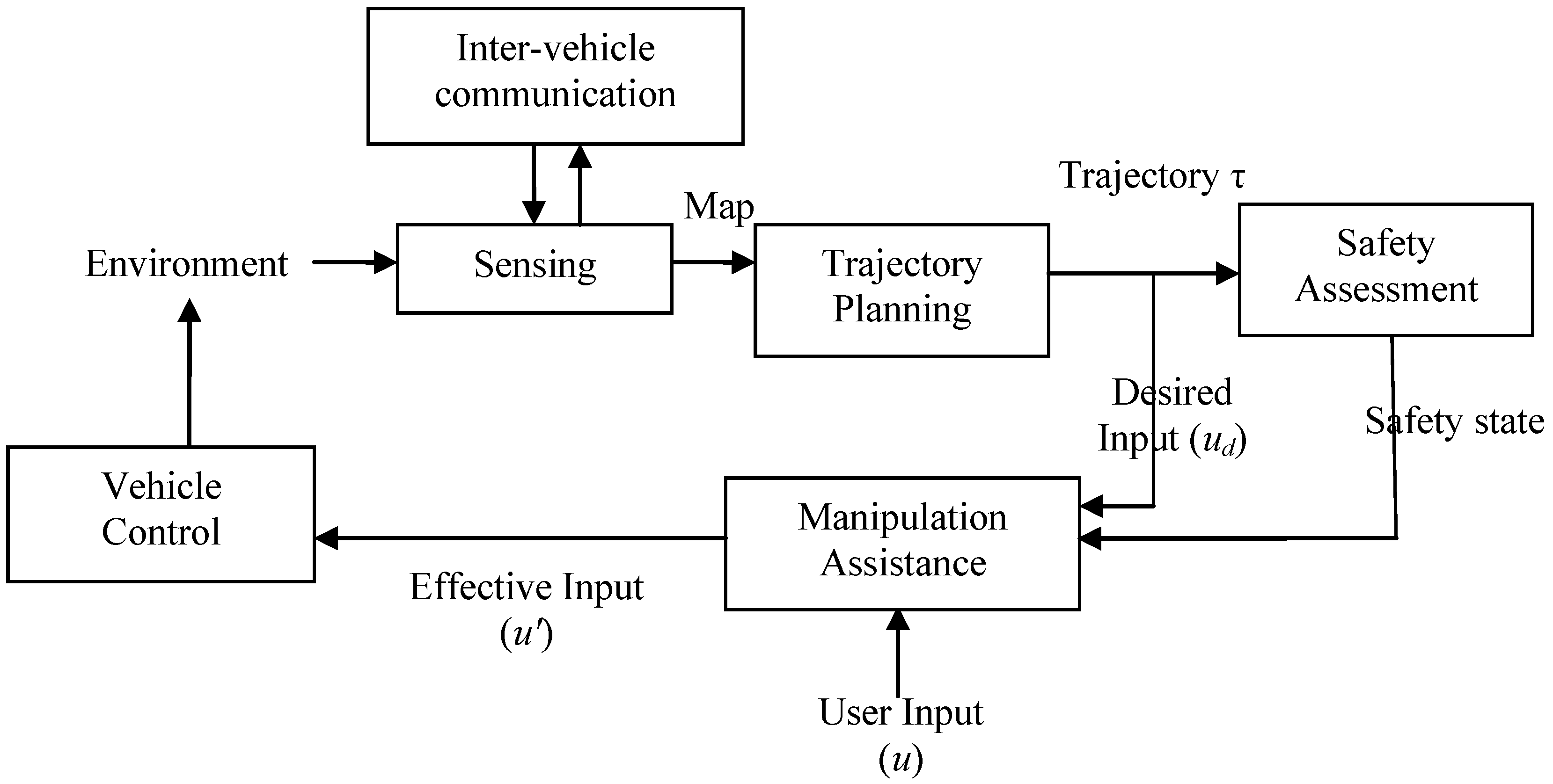
The other problem is to consider a control action. It is assumed that the user applies a control action of u at the current state. The trajectory, τ, is assessed to compute the safety of the current state. Let the desired input to trace the constructed trajectory be ud. The algorithm, hence, needs to modify the control input to produce a control input, u’, used for the navigation of the vehicle, such that the user barely feels the difference, while the control used for navigation is still safe. This means when the vehicle is in a very safe state, the user input, u, is used for navigation. However, in a very collision-prone state, effectively, the vehicle drives itself until a safe state is reached. The general framework is given by Figure 1.
Figure 1. General architecture of the assistance system.
Robotics 02 00019 g001

3.2. Initializing Visibility Graph

The visibility graph G(V, E) needs to be constructed based upon the sensed obstacles. This sub-section deals with the computation of the node set, V. The first type is obstacle nodes. Using these nodes, the vehicle can avoid an obstacle. Since, in a structured environment, the optimal (length only) trajectory of a point vehicle goes through the obstacle corners, the initial position of these nodes is taken to be just outside the obstacle corners. Let an obstacle be positioned at pi with orientation θi, such that its four corners are at Robotics 02 00019 i002, Robotics 02 00019 i003, Robotics 02 00019 i004 and Robotics 02 00019 i005. The obstacle nodes are placed just outside the obstacle, given by Equation (1), where Robotics 02 00019 i006 is a small vector pointing radially outwards from the corner, Cij. Here, i covers vehicles, while j covers the corners of the ith vehicle:
Robotics 02 00019 i007
The second type of node is the vehicle following nodes. It may not be possible for a vehicle to avoid all the other vehicles before the end of the road, and hence, it may have to slow down and follow another vehicle. The purpose of the graph is to admit all the possible plans of the vehicle. While obstacle nodes admit the overtaking and obstacle avoidance plans, the vehicle following nodes are supposed to admit the plans, where the vehicle decides to follow some other vehicle. These nodes are taken at a distance of q behind every vehicle in R. Here, q is the safety distance, which allows the vehicle to actually slow down and follow.
Consider a vehicle located at pi with orientation θi. The lateral position (Y-axis, along the width of the road) is the same as that of pi. Let Robotics 02 00019 i008 be the corner of the vehicle at pi, which has the least longitudinal occupancy (most behind longitudinally, along the X axis, the length of the road). For the node to be admissible, it is necessary that it lies longitudinally ahead of the vehicle’s current longitudinal occupancy and, subsequently, further by a distance, so as to allow a turn (currently equal to the vehicles length). The longitudinal position of the node is taken at a distance q behind Robotics 02 00019 i008. These nodes may hence be given by Equation (2). Throughout the paper, for a point P(x,y), P[X] refers to the X axis component (x) and P[Y] refers to the Y axis component (y).
Robotics 02 00019 i009

3.3. Applying Lateral Potentials

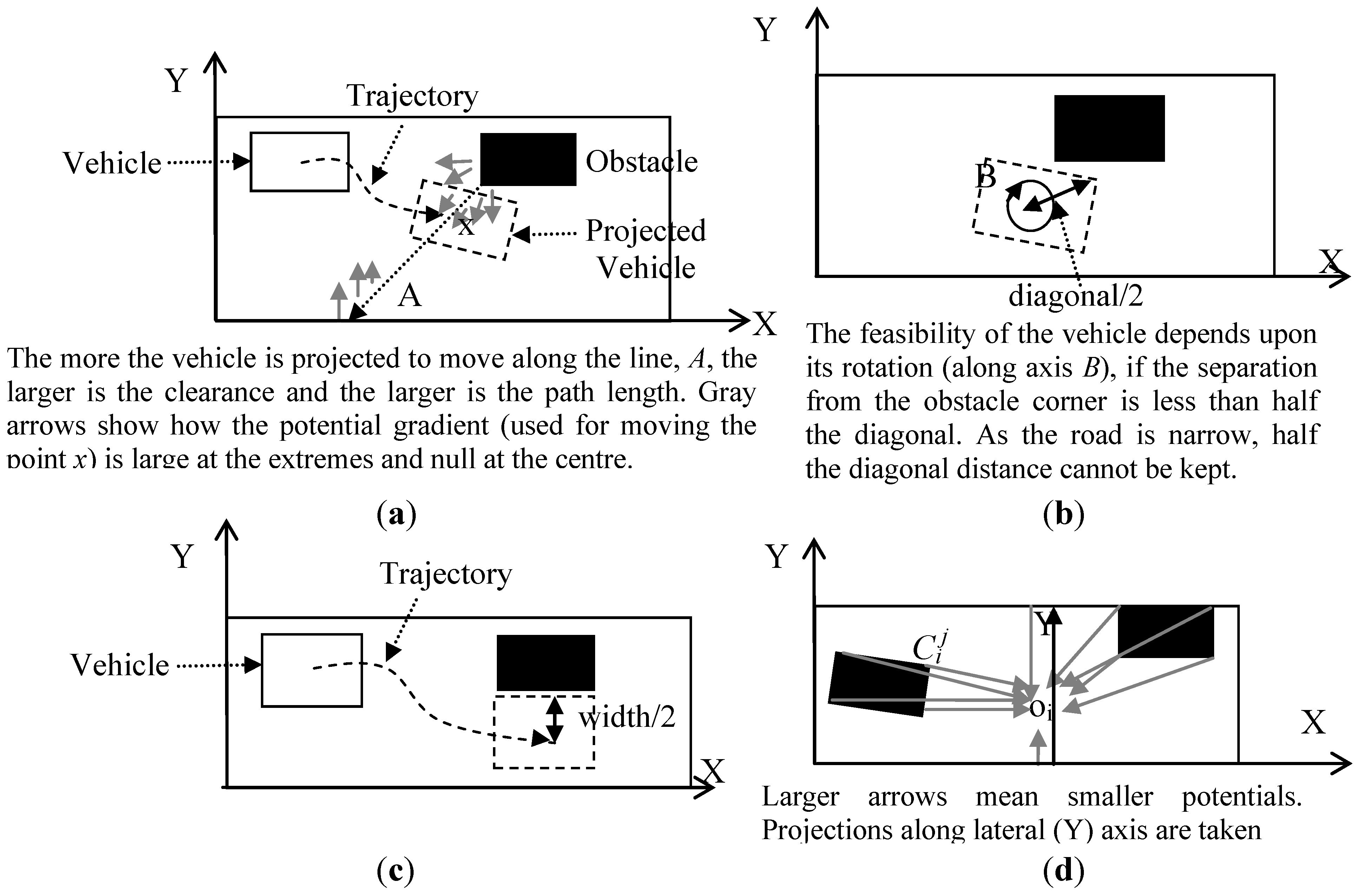
Since the vehicle is not point-sized, it is evident that the obstacle nodes (as initialized) cannot be used for navigation and need to be moved in proportion to the vehicle size. The movement should first cater to the feasibility considerations, such that a vehicle placed at the node does not collide with the obstacle. Subsequently, if additional distance is available, the node should be moved, so as to maintain a trade-off between path length and clearance. Excessive movement would make the paths too long, while small movements would result in small clearances. Obstacle nodes are placed very close to the obstacles and, hence, placement of the vehicle at the obstacle node implies zero clearance. As these nodes are moved away, the clearance increases at the cost of path length. Each node is affected by a repulsive potential from all the obstacles and the road boundaries. Such a motion of the nodes is carried out iteratively for a few iterations. In the small regions around the obstacles, the potential is large, and hence, the node is pushed back strongly until it reaches a point far enough, when potential almost dies off. If sufficient distance is not available, the node would lie in the middle of the obstacles. This is explained in Figure 2(a).
The other major issue is that the vehicle is rectangular, and its feasibility at a position (and hence the clearance) depends upon the orientation of the vehicle (Figure 2(b)). A popular approach [18] is to maintain a minimal distance equal to half the diagonal, which ensures that any orientation would lead to feasibility. Road scenarios are tightly packed, and hence, such extra space cannot always be kept. However, we exploit here the generally organized nature of a traffic landscape, where vehicles are generally driving along the road, unlike mobile robotics, where robots can be heading just about anywhere.
Consider, for example, a close overtake/obstacle avoidance. A vehicle would slide in from its current position to a position laterally just next to the vehicle/obstacle being avoided (Figure 2(c)). Hence, in the closest case, wherein no extra distance is available, the separation between the vehicle’s central position and the obstacle boundary would be half the vehicles width (say W/2). In other words, potentials can be applied in order to keep a distance of W/2 from obstacles to ensure feasibility.
Figure 2. Application of lateral Potentials. (a) Length and clearance trade-off. (b) Problem of rotation. (c) Heuristic of keeping minimum separation as half the width. (d) Sources of potential at a point oi.
Robotics 02 00019 g002
This heuristic, however, only holds when the obstacle avoidance point is located laterally next to the obstacle, unlike the diagonal version of a visibility graph approach or a potential direction of adaptive roadmaps (where multiple points are deployed per obstacle for framing an avoidance strategy). Hence, the potentials used for motion of the nodes are applied only in the lateral direction.
Consider an obstacle node located at a position oi. It is repelled by all the obstacles and the road boundaries. For computational constraints, the obstacles are assumed to be represented by only the corner points Robotics 02 00019 i008, each of which repels the node by a magnitude inversely proportional to the square of the distance. The road boundaries also act as obstacles and repel the node. The repulsion is, however, proportional to the shortest distance between the vehicle and the road boundaries. The resultant potential is given by Equation (3).
Robotics 02 00019 i010
The first term in Equation (3) denotes the potential due to obstacles, while the second and third terms denote the potentials from the left and right boundaries. One is kept as a minimum distance to avoid excessively large numbers as distances approach zero. Robotics 02 00019 i011 is the unit vector in the direction Robotics 02 00019 i008 to oi, and the projection of the resultant potential in the Y axis is considered. M is the road width. The sources of potential are explained in Figure 2(d).
At each iteration, obstacle nodes are moved as per the immediate potential, given by Equation (4).
Robotics 02 00019 i012
Here, α scales the potential to the immediate movement of the node, while β restricts the maximum amount by which the node may be moved.
Additional nodes are added. The first is the source node (s), which is the current position of the vehicle. This node has a single edge to a direction maintenance node, which ensures the initial trajectory is generated in the current heading direction of the vehicle (Φ). This node is taken at a distance of L from the current position s of the vehicle (or s + (Φ)). The last category is destination nodes (D), which are used to navigate the vehicle from obstacle avoidance points to the end of the road segment, so as to complete the trajectory within the segment, if feasible. A vehicle in the absence of any obstacle aims to maintain its lateral position on the road. This set of nodes is hence given by Equation (5), where Ω is the length of the road and Robotics 02 00019 i013 is the obstacle node after the application of the lateral potential:
Robotics 02 00019 i014
The vertex set V of the graph is hence given by Equation (6):
Robotics 02 00019 i015

3.4. Graph Search

The source node has a single edge, which is to the directional maintenance node. The rest of (|V| − 1)2 possible edges between all vertices are checked for feasibility. A configuration space, ξfree, is constructed, treating all the obstacles as static. The path between node Vi and node Vj traversed by the vehicle in the direction Vi to Vj is checked for feasibility in this configuration space. If the path is feasible, an edge is added.
A uniform cost search algorithm is applied over the graph to compute the best path. The trajectory cost function is taken as the trajectory length; however, a penalty is applied for small clearances. The lateral potential measured at the node is taken as the indicator of the clearance loss. This encourages the algorithm to find smaller and clearer paths. Since lateral potentials are already applied, all nodes, which could have reasonable clearances, obtain positions to allow these clearances. This means that the graph search practically works only on length, avoiding any node that could not obtain a reasonable clearance. Minimizing the length automatically results in maximizing smoothness. Further infeasible nodes (if any) have a very high penalty and are hence not used in the optimal trajectory.
Every node is associated with three types of cost. These are path length from the source (L), total clearance from the source (C) and total cost (Cost). In an expansion of a node Vj from node Vi, the costs are updated by Equations (7–9):
L(Vj) = L(Vi) + ||VjVi||
C(Vj) = C(Vi) + Z(Vj)
Cost(Vj) = L(Vj) + ρC(Vj)
Here, Z(Vj) is the potential measured at the point Vj and ρ is the penalty constant. Reasonably far from the obstacle, the potential is nearly zero and, hence, so is the penalization.
The search may not always end in a destination node, as it may not be possible to reach the end of the road segment, and instead, a vehicle may end up by following another vehicle. In such cases, the most distant node is chosen, and ties are broken on the basis of the total cost. This results in a path (τ') from the source to goal.
The path returned by the graph search (τ') needs to be additionally smoothed at the joints of the nodes; this is done by using spline curves. A coarser level trajectory is sampled and passed as control points for the construction of the spline curve. The resultant curve is taken to be the trajectory (τ) of the vehicle.

3.5. Trajectory Control

The trajectory obtained is assessed for a vehicle’s safety state. An unsafe state requires a greater manoeuvre, and hence, the trajectory is not very smooth. The minimum curvature along the trajectory is measured. In a discrete trajectory, at any general point at a distance of t on the vehicle’s trajectory (say τ(t)) the curvature (κ(τ(t))) is given by Equation 10, where d is a small number:
κ(τ(t)) = ||τ(t + d) + τ(td) - 2τ(t)||
Lesser curvatures give a safer state. This factor is normalized, so as to lie between zero and one.
Let the minimum curvature recorded on the trajectory be κ(τ). Consider at any instance the user gives an input, u, to the system. Based on the computed trajectory, let the desired input of the system, as per the computed trajectory, be ud, the magnitude of which depends upon the kinematic modelling and control system. The resultant input (u') given to the vehicle is then found from Equation (11):
Robotics 02 00019 i016
Here, κmin is the minimum threshold below, which the system has considered safe enough and the user is allowed to drive. κmax is the maximum threshold above which the system is considered unsafe and the human is disallowed to drive. In intermediate states, the resultant input is given as a weighted average of the desired and user inputs, which means that in this interval, the resultant input is gradually taken over from the user, as he/she drives with less of a safety margin.

4. Results

The algorithm was tested through simulations. The simulation tool took as input the sensed obstacles. Each of these had its own size and orientation with respect to the road. The obstacles were placed nearly in lanes, so as to make the scenario more realistic. However, the difference in sizes and orientations necessitated a non-lane-based trajectory planning. The initial position and orientation of the vehicle was also fed into the tool. The simulation tool assessed the scenario and computed the trajectory, which was displayed.
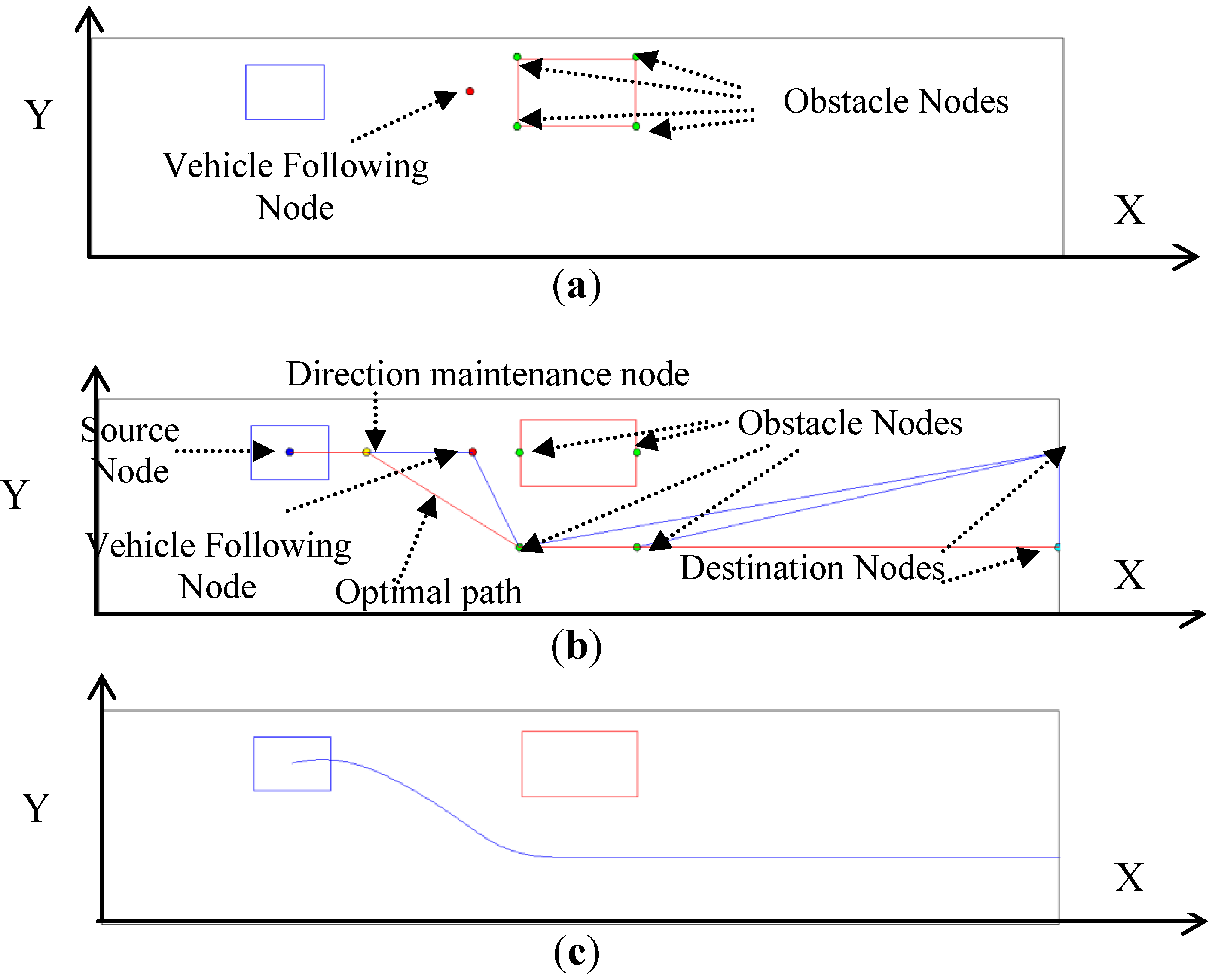
We first discuss here a step-by-step solution to the simplest task, which is that of obstacle avoidance. The vehicle had an obstacle in front of it, which it had to overcome. First, the obstacle nodes and the vehicle-following nodes were placed as shown in Figure 3(a). These nodes were acted upon by the lateral potentials and, hence, were moved, as shown in Figure 3(b). Figure 3(b) also shows the source node, direction maintenance node and the destination nodes. The edges were connected by feasibility analysis. The optimal path is shown separately. The smoothened trajectory is shown in Figure 3(d).
Figure 3. Results for obstacle avoidance. (a) Initial nodes. (b) Nodes after application of lateral potential. (c) Resultant trajectory.
Robotics 02 00019 g003
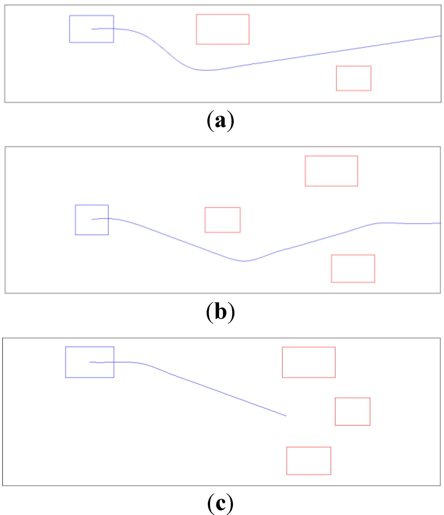
Figure 4. Experimental Results.
Robotics 02 00019 g004
The second scenario consisted of two obstacles (or vehicles). The first obstacle was larger than the second. The algorithm decided to pass the first obstacle on its right-hand side and the second obstacle on its left-hand side, which is (arguably) the best strategy to take. The resultant trajectory is shown in Figure 4(a).
To test the scalability of the approach, another obstacle was added into the scenario. The resultant scenario consisted of an obstacle just ahead of the vehicle to avoid, which meant that it must turn to the left or right. However, other obstacles were positioned on either side. The algorithm decided to make the vehicle turn right, as it would later find a smaller obstacle, which was easier to avoid. Taking a left turn initially could have made the subsequent traversal risky. The resultant trajectory for the scenario is shown in Figure 4(b).
In the last scenario, the road was completely blocked by vehicles. Hence, the vehicle under control needed to decide which vehicle in front to follow. The choice was such that the vehicle reached the most distant point, and hence, the central position was chosen. This trajectory is shown in Figure 4(c).
An attempt was made to gradually take control of the vehicle from the human driver, for which curvature was used as an indicator. The best way to study this effect is the obstacle-avoidance scenario. Experiments were performed over a set of points, which varied in their distance from the obstacle. As the vehicle went near to the obstacle, there was an increase in the curvature, which indicated a higher risk. Hence, if the human driver did not see the obstacle and kept driving, the algorithm would gradually intervene. The trajectories for different positions are shown in Figure 5(a), while the corresponding change in the curvature values is shown in Figure 5(b).
Figure 5. Effect of change in heading distance to the obstacle. (a) Trajectories (b) Curvature.
Robotics 02 00019 g005
Figure 6. Effect of change in orientation to the obstacle. (a) Trajectories (b) Curvature.
Robotics 02 00019 g006
The risk is not always due to the distance of the vehicle from the obstacle; it can also be due to the heading direction. This factor was also tested. The same position of the vehicle was tested for safety for various values of the heading direction. The corresponding trajectories are shown in Figure 6(a), and the curvatures are plotted in Figure 6(b). An anti-clockwise turn is obviously risky, since the vehicle has to turn by a greater magnitude. This is confirmed by a significant rise in curvature. The figure also shows that a clockwise turn is also associated with a slightly higher risk, as it makes the turn a little more difficult.

5. Conclusions

In this paper, it was assumed that the environment can be sensed using a variety of sensors, in cooperation with the other vehicles using an inter-vehicle communication system. The sensed environment was used by a trajectory planner. The planning algorithm employed a hybrid of visibility graphs and an adaptive roadmap. A number of additional nodes were added, as per the problem requirements.
The motion of the nodes of the graph was restricted to the lateral direction only, which gives rotational invariance to the algorithm. Uniform cost search was used on the resultant map, and the path was smoothened using spline curves. The problem was solved on a variety of typical scenarios. In each scenario, the task was to construct a trajectory to successfully avoid all the obstacles, failing which it was preferred to follow a vehicle instead. As the vehicle approached an obstacle, a rise in curvature was observed. This can be used to smoothly change the control from a human driver to the assistance system. A similar observation was made on the rotation of the vehicle.
The motivation was to design and implement the complete assistance system. Currently, the biggest limitation of the work is that the system cannot be simulation-based on human inputs. Hence, the physical manipulation is restricted to motivation only. The simulation needs to be extended to a virtual driving system, over which a human can be made to control a vehicle in assistance with the designed system. In terms of trajectory generation, better trajectory cost functions need to be considered, which match perfectly with the human preferences. Based on the human generated inputs, it may be necessary to assess the intent of the human, rather than just assuming the human takes the best decisions based on the current pose. Ultimately, testing on a physical vehicle is necessary to validate performance.
It should also be noted that, due to the simplified modelling of the vehicle, the trajectory planning algorithm in its current form would not be suitable for application in a real traffic scenario. This is due to the fact that considerations, such as side slip (swerving) are not taken into account; however, this may be improved by use of a more sophisticated vehicle model. Traffic rules govern the decision whether a lane change is possible or not, which in the current system is decided purely by the human driver. The system cannot alter the decision, and hence, the interpretation of the traffic rules for safety consideration is entirely up to the human driver. Currently, the system makes every such change safe by modification of steering or travel speeds. Disallowing lane changes or overtaking depending upon the traffic rules directly by the algorithm may well be taken into account in future versions of the algorithm.
One important question, which has not been dealt with here, is how much a human driver would be willing to allow a computer-based system to take over vehicle control. Clearly, this is a much bigger problem than can be tackled in a paper of this type, which is concerned primarily with the technical aspects of bringing this possibility about. In such a situation, many different social pressures and requirements come into effect and, as with all computer-based control systems, a vitally important aspect is ultimate confidence in performance delivery on the part of the computer system. Hence, there is a need for realistic simulation runs and subsequent practical scenario trials in order to prove the validity and safety of the computer system.

Acknowledgments

The authors wish to thank the Commonwealth Scholarship Commission in the United Kingdom and the British Council for their support of the second named author through the Commonwealth Scholarship and Fellowship Program—2010—UK award number INCS-2010-161.

References

  1. Hummel, T.; Kühn, M.; Bende, J.; Lang, A. Advanced Driver Assistance Systems: An Investigation of Their Potential Safety Benefits Based on an Analysis of Insurance Claims In Germany; Research report FS 03; German Insurance Association (GDV): Berlin, Germany, 2011. [Google Scholar]
  2. Gerónimo, D.; López, A.M.; Sappa, A.D.; Graf, T. Survey of pedestrian detection for advanced driver assistance systems. IEEE Trans. Pattern Anal. Mach. Intell. 2010, 32, 1239–1258. [Google Scholar] [CrossRef]
  3. Sarshar, M. A Novel System for Advanced Driver Assistance Systems. In Proceedings of the 4th Annual IEEE Systems Conference, San Diego, CA, USA, April 2010; pp. 529–534.
  4. Trivedi, M.M.; Cheng, S.Y. Holistic sensing and active displays for intelligent driver support systems. Computer 2007, 40, 60–68. [Google Scholar] [CrossRef]
  5. Trivedi, M.M.; Gandhi, T.; McCall, J. Looking-in and looking-out of a vehicle: Computer-vision-based enhanced vehicle safety. IEEE Trans. Intell. Transport. Syst. 2007, 8, 108–120. [Google Scholar] [CrossRef]
  6. Cellario, M. Human-centered intelligent vehicles: Toward multimodal interface integration. IEEE Intell. Syst. 2001, 16, 78–81. [Google Scholar] [CrossRef]
  7. Hannan, M.A.; Hussain, A.; Samad, S.A. Sensing systems and algorithms for airbag deployment decision. Sensors 2011, 11, 888–890. [Google Scholar]
  8. Parasuraman, R.; Hancock, P.A.; Olofinboba, O. Alarm effectiveness in driver-centred collision-warning systems. Ergonomics 1997, 40, 390–399. [Google Scholar] [CrossRef]
  9. Stein, G.P.; Mano, O.; Shashua, A. Vision-Based ACC with a Single Camera: Bounds on Range and Range Rate Accuracy. In Proceedings of the IEEE Intelligent Vehicles Symposium, Columbus, OH, USA, 9–11 June 2003; pp. 120–125.
  10. Schlegl, T.; Bretterklieber, T.; Neumayer, M.; Zangl, H. Combined capacitive and ultrasonic distance measurement for automotive applications. Sensors 2011, 11, 2636–2642. [Google Scholar] [CrossRef]
  11. Dams, M.; Winner, H. A Modular System Architecture for Sensor Data Processing of ADAS Applications. In Proceedings of the IEEE Intelligent Vehicles Symposium, Las Vegas, NV, USA, 6–8 June 2005; pp. 729–734.
  12. Tsugawa, S. Inter-Vehicle Communications and Their Applications to Intelligent Vehicles: An Overview. In Proceedings of the IEEE Intelligent Vehicle Symposium, Versailles, France, 17–21 June 2002; pp. 564–569.
  13. Reichardt, D.; Miglietta, M.; Moretti, L.; Morsink, P.; Schulz, W. CarTALK 2000: Safe and Comfortable Driving Based upon Inter-Vehicle-Communication. In Proceedings of the IEEE Intelligent Vehicle Symposium, Versailles, France, 17–21 June 2002; pp. 545–550.
  14. Khatib, O. Real-Time Obstacle Avoidance for Manipulators and Mobile Robots. In Proceedings of the 1985 IEEE International Conference on Robotics and Automation, St. Louis, MO, USA, March 1985; pp. 500–505.
  15. Stentz, A. Optimal and Efficient Path Planning for Partially-Known Environments. In Proceedings of the 1994 IEEE International Conference on Robotics and Automation, San Diego, CA, USA, 8–13 May 1994; pp. 3310–3317.
  16. Choset, H.; Burdick, J. Sensor Based Planning. I. The Generalized Voronoi Graph. In Proceedings of the 1995 IEEE International Conference on Robotics and Automation, Nagoya, Japan, 21–27 May 1995; pp. 1649–1655.
  17. Fiorini, P.; Shiller, Z. Motion Planning in Dynamic Environments Using Velocity Obstacles. Int. J. Roboti. Res. 1998, 17, 760–772. [Google Scholar] [CrossRef]
  18. Wesley, M.A.; Lozano-Pérez, T. An algorithm for planning collision-free paths among polyhedral obstacles. Comm. ACM 1979, 22, 560–570. [Google Scholar] [CrossRef]
  19. Oommen, B.; Iyengar, S.; Rao, N.; Kashyap, R. Robot navigation in unknown terrains using learned visibility graphs. Part I: The disjoint convex obstacle case. IEEE J. Robot. Autom. 1987, 3, 672–681. [Google Scholar] [CrossRef]
  20. Keller, C.G.; Dang, T.; Fritz, H.; Joos, A.; Rabe, C.; Gavrila, D.M. Active pedestrian safety by automatic braking and evasive steering. IEEE Trans. Intell. Transport. Syst. 2011, 12, 1292–1304. [Google Scholar] [CrossRef]
  21. Jensen, M.J.; Tolbert, A.M.; Wagner, J.R.; Member, S.; Switzer, F.S.; Finn, J.W. A customizable automotive steering system with a Haptic feedback control strategy for obstacle avoidance notification. IEEE Trans. Veh. Tech. 2011, 60, 4208–4216. [Google Scholar] [CrossRef]
  22. Mulder, M.; Abbink, D.A.; van Paassen, M.M.; Mulder, M. Design of a Haptic gas pedal for active car-following support. IEEE Trans. Intell. Transport. Syst. 2011, 12, 268–279. [Google Scholar] [CrossRef]
  23. Kavraki, L.E.; Kolountzakis, M.N.; Latombe, J.C. Analysis of probabilistic roadmaps for path planning. IEEE Trans. Robot. Autom. 1998, 14, 166–171. [Google Scholar] [CrossRef]
  24. Kavraki, L.E.; Svestka, P.; Latombe, J.C.; Overmars, M.H. Probabilistic roadmaps for path planning in highdimensional configuration spaces. IEEE Trans. Robot. Autom. 1996, 12, 566–580. [Google Scholar] [CrossRef]
  25. Gayle, R.; Sud, A.; Lin, M.C.; Manocha, D. Reactive Deformation Roadmaps: Motion Planning of Multiple Robots in Dynamic Environments. In Proceedings of the 2007 IEEE/RSJ International Conference on Intelligent Robots and Systems, San Diego, CA, USA, 29 October–2 November 2007; pp. 3777–3783.
  26. Quinlan, S.; Khatib, O. Elastic Bands: Connecting Path Planning and Control. In Proceedings of the 1993 IEEE International Conference on Robotics and Automation, Atlanta, GA, USA, 2–6 May 1993; pp. 802–807.
  27. Anderson, S.J.; Karumanchi, S.B.; Iagnemma, K. Constraint-Based Planning and Control for Safe, Semi-Autonomous Operation of Vehicles. In Proceedings of the 2012 IEEE Intelligent Vehicles Symposium, Madrid, Spain, 3–7 June 2012; pp. 383–388.
  28. Kala, R.; Warwick, K. Multi-vehicle planning using RRT-connect. Paladyn J. Behav. Robot. 2012, 2, 134–144. [Google Scholar] [CrossRef]
  29. Kala, R.; Warwick, K. Planning of Multiple Autonomous Vehicles Using RRT. In Proceedings of the 10th IEEE International Conference on Cybernetic Intelligent Systems, London, UK, September 2011; pp. 20–25.
  30. Kuwata, Y.; Karaman, S.; Teo, J.; Frazzoli, E.; How, J.P.; Fiore, G. Real-time motion planning with applications to autonomous urban driving. IEEE Trans. Contr. Syst. Tech. 2009, 17, 1105–1118. [Google Scholar] [CrossRef]
  31. Schubert, R.; Schulze, K.; Wanielik, G. Situation assessment for automatic lane-change maneuvers. IEEE Trans. Intell. Transport. Syst. 2010, 11, 607–616. [Google Scholar] [CrossRef]
  32. Hegeman, G.; Tapani, A.; Hoogendoorn, S. Overtaking assistant assessment using traffic simulation. Transport. Res. C 2009, 17, 617–630. [Google Scholar] [CrossRef]
  33. Naranjo, J.E.; González, C.; García, R.; de Pedro, T. Lane-change fuzzy control in autonomous vehicles for the overtaking maneuver. IEEE Trans. Intell. Transport. Syst. 2008, 9, 438–450. [Google Scholar] [CrossRef] [Green Version]
  34. Gayle, R.; Moss, W.; Lin, M.C.; Manocha, D. Multi-Robot Coordination Using Generalized Social Potential Fields. In Proceedings of the 2009 IEEE International Conference on Robotics and Automation, Kobe, Japan, 12–17 May 2009; pp. 106–113.
  35. Gayle, R.; Manocha, D. Navigating Virtual Agents in Online Virtual Worlds. In Proceedings of the 13th International Symposium on 3D Web Technology, Los Angeles, CA, USA, April 2008; ACM: New York, NY, USA; pp. 53–56.
  36. Kala, R.; Shukla, A.; Tiwari, R. Robotic path planning in static environment using hierarchical multi-neuron heuristic search and probability based fitness. Neurocomputing 2011, 74, 2314–2335. [Google Scholar] [CrossRef]
  37. Kala, R.; Warwick, K. Multi-level planning for semi-autonomous vehicles in traffic scenarios based on separation maximization. J. Intell. Robotic Syst. 2013. [Google Scholar] [CrossRef]
  38. Cagigas, D.; Abascal, J. A hierarchical extension of the D* algorithm. J. Intell. Robotic Syst. 2005, 42, 393–413. [Google Scholar] [CrossRef]
  39. Kala, R.; Warwick, K. Motion planning of autonomous vehicles in a non-autonomous vehicle environment without speed lanes. Eng. Appl. Artif. Intell. 2013. [Google Scholar] [CrossRef]