Review

Biomimetic Spider Leg Joints: A Review from Biomechanical Research to Compliant Robotic Actuators

Faculty of Mechanical Engineering—Bionicum Research/3D-Visualisierungszentrum, Nuremberg Institute of Technology—Georg Simon Ohm, Nuremberg D-90489, Germany
*
Author to whom correspondence should be addressed.
Robotics 2016, 5(3), 15; https://doi.org/10.3390/robotics5030015
Submission received: 30 May 2016 / Revised: 6 July 2016 / Accepted: 7 July 2016 / Published: 15 July 2016

Abstract

:
Due to their inherent compliance, soft actuated joints are becoming increasingly important for robotic applications, especially when human-robot-interactions are expected. Several of these flexible actuators are inspired by biological models. One perfect showpiece for biomimetic robots is the spider leg, because it combines lightweight design and graceful movements with powerful and dynamic actuation. Building on this motivation, the review article focuses on compliant robotic joints inspired by the function principle of the spider leg. The mechanism is introduced by an overview of existing biological and biomechanical research. Thereupon a classification of robots that are bio-inspired by spider joints is presented. Based on this, the biomimetic robot applications referring to the spider principle are identified and discussed.

1. Introduction

Human-Robot-Interaction (HRI) is indispensable in assembly and handling tasks in industrial manufacturing, as well as in medical and rehabilitation applications. Direct collaboration between the machine and humans enhances the flexibility and productivity in industrial tasks [1] and it enables direct assistance for infirm or disabled people in medical applications [2,3]. Despite significant advantages, direct contact and “hand-in-hand” cooperation with robots is often avoided. As collisions with powerful and rigid robot arms can cause serious injuries and bruising through impact, compliance of robotic actuators has to be ensured in instances of contact with humans. And consequently, there are safety-related issues and strict restrictions for the machines [4].
First generation assistance robots are already in use in industrial applications and enable direct HRI. Since these robots use electrical drives, they have to be set up with expensive and complex sensory equipment to avoid hard collisions with humans [5,6,7]. However, when considering the recent developments of robotic actuators for HRI, a turnaround can be seen, away from rigid drives with artificial flexibility to the intelligent use of soft materials with intrinsic compliance and structural integration [8]. Moreover, a look at the fauna shows that the extremities of most animals are flexible as well because biological motion systems have an intrinsic aim to avoid damage. Therefore, the elastic yielding of actuation elements—muscles, tendons, etc.—enables the continuous damping of impacts and collisions [9].
Biomimetic or “soft robotic” actuators are based on the same principle and make use of their inherent compliance to fulfill safety requirements. Elastic compliance of flexible structure elements is used to avoid injuries in case of a collision with a human. This type of actuation has attributed all kinds of robotic applications and machine designs [10]. Therefore, intensive research on biomimetic robotics has been carried out in the last decade to find novel actuation systems [11,12]. Mammals and most arthropods, such as stick insects, generate their movements by a muscular system, typically in antagonistic arrangement [13]. Contrary to that, a special class of arthropods—the arachnids—use a hydraulic system to straighten the legs [14]. The characteristics of spider legs are multi-fold: On the one hand, they are highly sensitive, move gracefully and have a lightweight design, which is apparent, since some spiders are able to walk on the surface of water [15]. On the other hand, for hunting and climbing tasks, an impressive dynamic and powerful actuation can be observed [16,17]. Thus, the spider leg system combines flexible and lightweight movements with powerful actuation; it is a biological showpiece for biomimetic applications and perfectly corresponds to major requirements for modern robotic applications.
This correspondence and the characteristics of the system motivated an investigation of the biological research done on this principle and its technical adaptation as biomimetic robotic actuators is carried out in this work.

2. Biological Research

It is well established that the principle of spider leg’s function is contrary to the muscular antagonism, which can be found in extremities of other animals and humans. The spider leg consists of seven distinct, tubular segments that build an exoskeleton, which surrounds and protects all of the inner entities. From a functional point of view, the seven links of each leg can be reduced to three main acting joints used for walking [18,19]: the complex, muscle-actuated hip joint assembly with two degrees of freedom for stance and pan as well as the two main leg joints, the femur-patella and the tibia-metatarsus joints. Both of them show one rotational degree of freedom [20]. Biomechanical investigations show that the one degree of freedom connection between these two joints can mechanically be considered classical pivot joints, which are located near the peripheral point on the dorsal side of the leg cross section [21].
The legs are connected to the prosoma—the central body of the spider—and are almost completely filled by muscles. Due to the open blood circulatory system, all of the space between the muscles and the exoskeleton—called lacunae—is filled with hemolymph [22,23]. To illustrate, Figure 1a shows a sectional sketch of a tibial segment; the muscles are situated longitudinally inside the exoskeleton and are connected to the subsequent part of the exoskeleton [24]. A contraction of the muscles initiates a retraction of the subsequent segment. In the cross sections from A–A to D–D, the muscles are illustrated with black areas, whereas the white areas between muscles and exoskeleton show the lacunae [20].
The axis of rotation is on the peripheral point on the dorsal side of the exoskeleton segments. The muscles can only create tension forces by contraction. Consequently, these two most important leg joints cannot be extended by muscular actuation. Therefore, a flexible membrane is situated on the ventral side of these pivot joints. The membranes are inflated by an increase in the hemolymph pressure inside the leg, which initiates the extension [16].

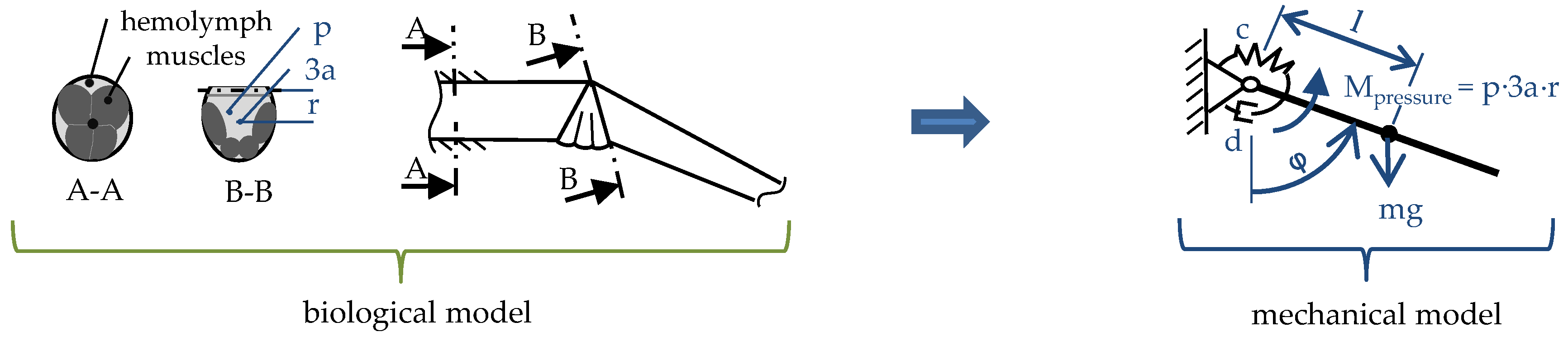
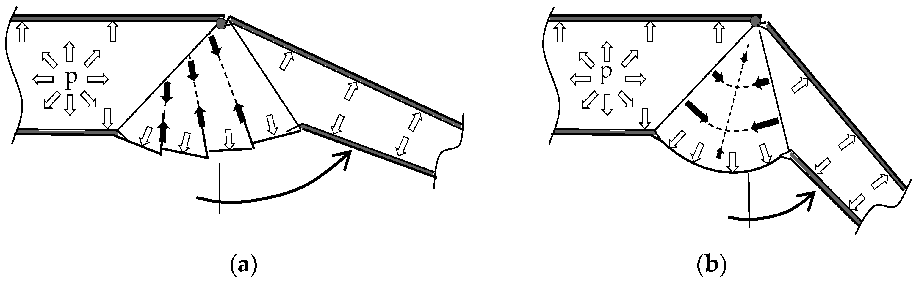
2.1. Hydraulic Leg Extension

First findings on hydraulic leg extension are from Pretrunkevitch [25] and Brown [26] who determined that there are no muscles to generate an extension of the femur-patella or the tibia-metatarsus joints. Thereupon Ellis [27] disproved previous assumptions [25] that the extension is solely generated by the membrane’s elasticity and provided the experimental evidence for a relationship between the internal fluidic pressure in the spider leg and the joint extension. Parry and Brown [28] then experimentally determined values and roughly calculated relations for pressure, torque, and fluidic volumes. Investigations by Wilson [29] show that the main fluidic pressure difference during leg extension is generated by a contraction of the prosoma. This was confirmed by Stewart and Martin [30], as well as Anderson and Prestwich [31] through their investigations of time-dependent pressure levels during leg movement. Thereupon profound research was done by Blickhan and Barth [22] measuring the strains in the exoskeleton by placing strain gauges on the surface of the exoskeleton cuticle.
Experimental results were used to draw conclusions on the resulting torque and how the biomechanical inflation of the membrane works in detail: One significant aspect concerning the articular membrane is the bellow-like folding of the flexible structure. Figure 2 is used to clarify this point by an approach done by Blickhan and Barth [22]. An increase of the internal hemolymph pressure (⇧) leads to an expansion of the joint section, which causes stresses in the membrane cuticle. The direction of the highest stress vectors is illustrated with (⬆). A pressurized isotropic structure (right) of the cuticle causes maximum tension between the distal metatarsus and the proximal tibia segment. This tension stress is contrary to the joint movement and diminishes the extension torque. In opposition, an accordion-like structure of the membrane is inflating instead of being stretched in axially to the leg. Consequently less axial stress obstructing the extension torque between the exoskeleton parts is occurring at the same joint angle. However, the reduction of the axial load components results in an increase of the radially occurring stress components (⬆), which are resolved at the dorsal side of the tibia segment.
Microscope images of a pressurized membrane during leg movement (Figure 3a) show that the radial structure of the membrane is reinforced by a tendon-like design (emphasized with black arrows). This clearly supports the statement that the main load is occurring in the radial direction and the resolution of the tension stress can be attributed to the reinforcement.
Examinations of femur-patella and tibia-metatarsus joints with unpressurized membranes were carried out to examine the fold design of spider’s joint membranes more closely. This provided insight to the design with a view to building technical prototypes. Therefore, Figure 3b shows scanning electron microscope (SEM) images of a Lasidora Parahybana’s tibia-metatarsus joint membrane and Figure 3c illustrates micro CT scans of a femur-patella joint (Cupiennius Salei). Analyzing the SEM images and the micro CT-based three-dimensional model, we estimate that for technical interpretations, three folds adequately meet the requirements to reflect the bellow-like structure.
Also important for a biomimetic transfer into a robotic actuator are biomechanical calculations of the hydraulic extension. Zentner [32,33,34] mathematically described the rotational extension of the spider leg joint by using a rigid body modelling, schematically illustrated in Figure 4.
It can be assumed that the extension of the leg is solely generated by an increase of the pressure p affecting three estimated lacunae with an area a, and an effective lever r from the pivot point to the center of the area. The center of gravity is located at a distance l to the pivot point. Muscles inside the legs are accounted for by a rotational spring stiffness c resulting in a retracting torque and damping coefficient d [35]:
J × φ ¨ = m × g × l × sin φ + p ( 3 a ) × r d × φ ˙ c × Δ φ
An experimental setup [35] was used to determine the parameters of this theoretical approach and to verify the model. For this, a separated spider leg was fixed on a test rig for pumping fluid into the exoskeleton while measuring pressure, angle, and time. After a positive evaluation, the model was extended to a three-degrees-of-freedom, multibody model [35].

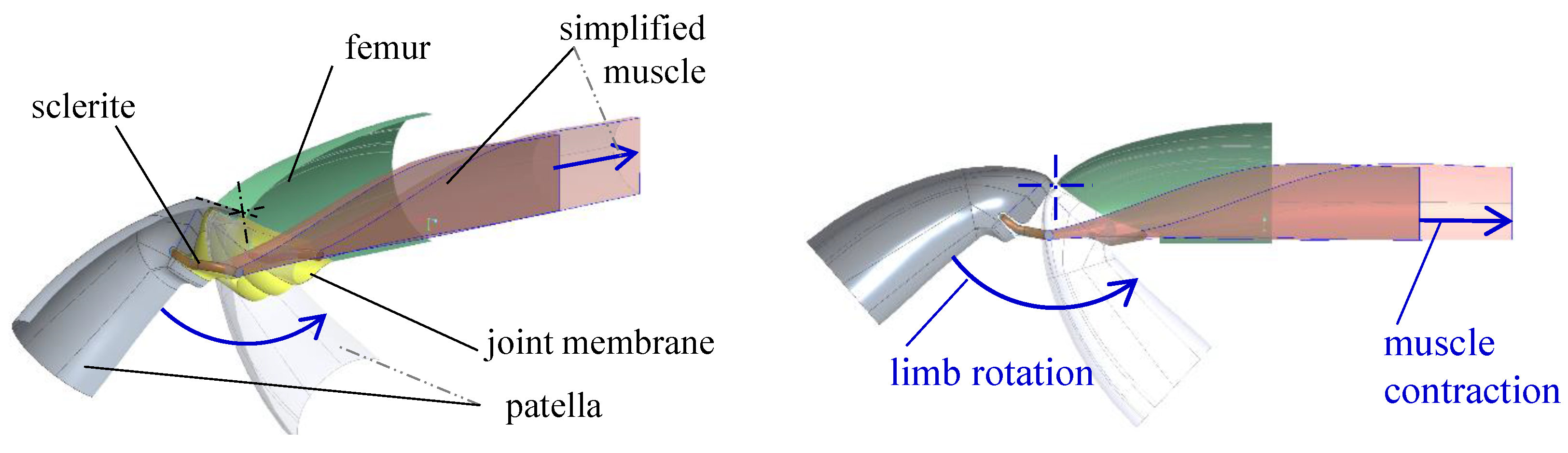
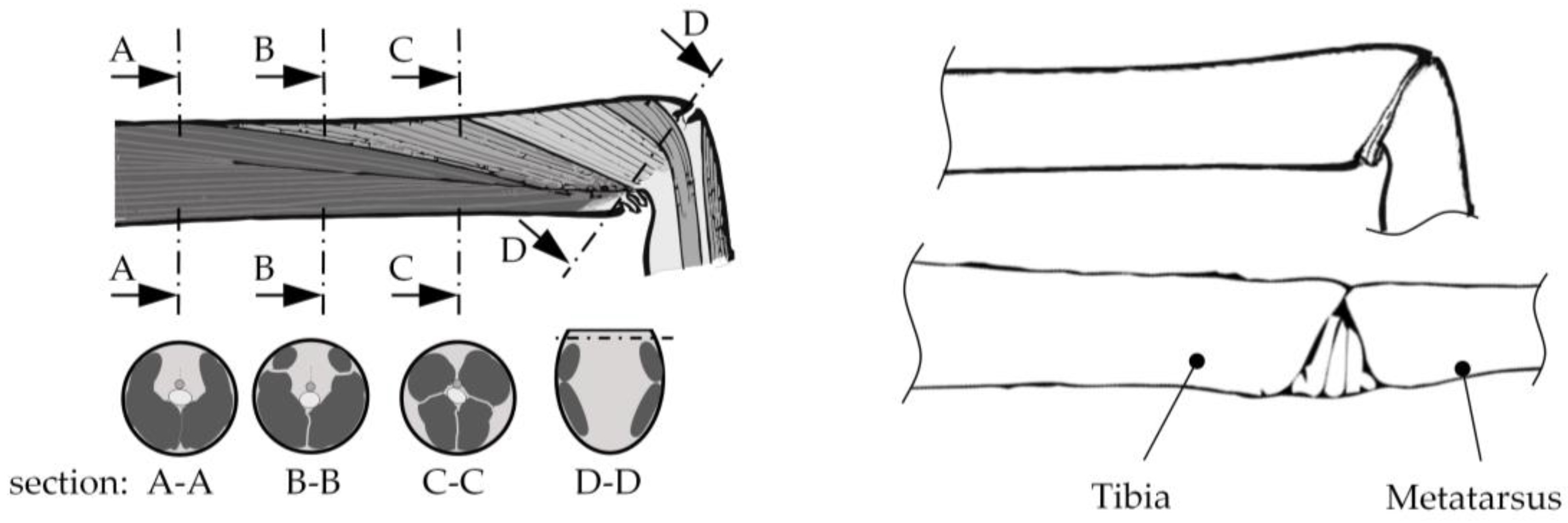
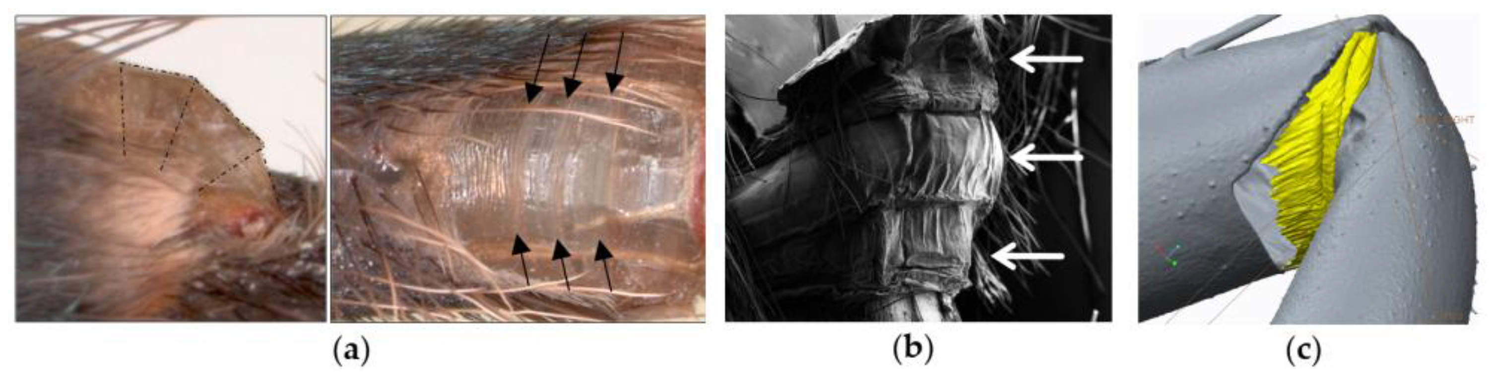
2.2. Muscular Flexion and Its Biomechanical Aspects

Although a lot of research is focused on the hydraulic extension, the muscles also play an important role and need to be considered. The lack of extension muscles in the main joints leads to the important fact that almost the whole space inside the exoskeletal tubes can be filled with flexion muscles [36,37]. As mentioned, the contraction of the longitudinal muscles generates retraction forces and initiates a powerful flexion. This is necessary because the muscular flexion is the main actor for gripping prey as well as for climbing or rappelling. Some researchers even assume that the lack of extension musculature is a result of maximizing the flexion force [31].
The flexors are not directly connected to the distal segment of the exoskeleton but to an intermediate sclerite with a flexible connection. At the femur-patella joint this is a chitin ring (patella sclerite) and at the tibia-metatarsus joint the sclerite is a flexible lamella that acts as the transition to the proximal border of the metatarsal segment, which protrudes into the joint section. This biomechanical constellation is assumed to enable the maximum flexing torque for every joint angle due to an ideal lever of the retracting force [20,37].
Subsequent biomechanical studies by Siebert et al. [38] simplified the flexors inside the tibia to one representative contractor and experimentally investigated the force-length relationship and the force-velocity relationship of the metatarsus flexors. Therefore, a parabolic flexing torque-angle relationship and a nearly linear relationship between contraction length and joint angle was determined [38]. To illustrate this biomechanical principle, a three-dimensional model of the femur-patella joint was derived from micro CT scans of a Cupiennius Salei [39]. Based on this data, a simplified and scaled multibody model to verify geometrical dependencies was created using reverse engineering techniques. The model is shown in Figure 5 and demonstrates the joint angle movement of the patella (grey) due to a contraction of the representative muscle (red) whose endpoint is connected to the patella sclerite (brown). The transparent elements show the flexed positions.

2.3. Interaction of Hydraulic Extension and Muscular Flexion

Generally, the biomechanical spider leg mechanism is an antagonistic counterplay of hydraulically initiated extension and muscular flexion, so spiders are semi-hydraulic machines [40]. It has been shown that the contraction of the prosoma generates an increase of hemolymph pressure in all legs simultaneously [41] and the pressure rise takes place 10 ms before the start of movements [38]. This, in turn, means the muscles have to be tensed at this point in time to prevent a synchronous extension of all legs [20]. Consequently, the antagonistic flexors can allow the pressure-driven extension of individual joints by relaxing. Thus, it is assumed that the muscular flexors are the controlling units of the tibia-metatarsus and femur-patella joints. During movements, the antagonistic system of constantly increased pressure to provide extension torque and active retracting muscles can be thought of as an “inverted marionette”. However, we are still far from knowing exactly which muscles produce the pressure coming from the central body [41]. Additionally, due to this antagonistic counterplay, complex fluid mechanic reactions are taking place during the leg movements. As mentioned, the intermediate spaces between muscles and exoskeleton define the channels for hemolymph transport. While a joint is being flexed, the muscles are contracting and swelling radially, which consequently narrows these lacunae. At the same time, hemolymph is displaced from the folding joint section and has to pass these channels. But the narrowed intermediate spaces restrict the hemolymph flow. This leads to local increases in pressure [22]. Kropf [41] compared different measurements [28,30,31,42] of hemolymph pressure over time; he registered 0.01–0.15 bar during rest and an increase to levels from 0.1 to 0.64 bar during movements. Pressure peaks of 0.7 bar and higher where measured during struggling [22]. Sensenig [43] did first studies on these high pressures peaks during fast movements and determined an energy storage due the elasticity of the cuticle.
The spider leg mechanism has been extensively researched with regard to the biomechanical principles involved. These principles have been translated into biomimetic applications; those that are specifically inspired by spider leg joints are reviewed in the following section.

3. Technical Applications

The technical part of this review first classifies the rubric of robotics, where biomimetic spider actuators can be found. Second, the actuation and structural design principles of these bio-inspired, fluidic joint actuators are introduced. Based on this, an overview of bio-inspired actuators directly related to the spider leg principle is presented.

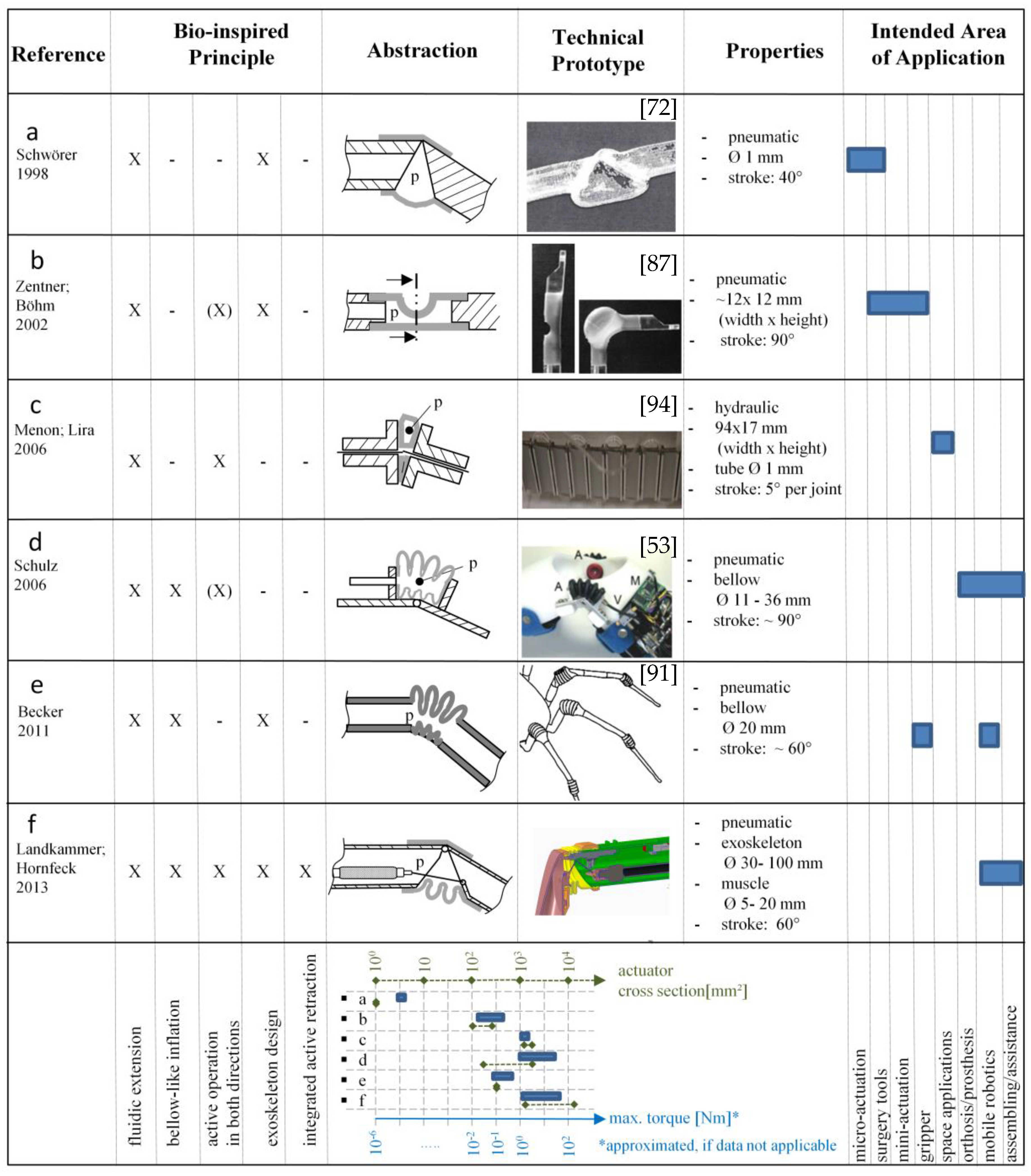
3.1. Classification of Biomimetic Spider Leg Actuators

Compliant robotic actuators can be differentiated into two rubrics, illustrated in Figure 6. On the one hand, conventional robots which are equipped with excessive control and sensory to actively generate compliance [5,6,7]. One the other hand, robots with inherent, passive compliance due to the use of flexible materials or soft actuation [8,44]. Many of them are inspired by biological principles. But not all robots with inherent compliance are biomimetic. There are three critical points which have to be fulfilled to name a device biomimetic or bio-inspired [45]. Biomimetic devices must have:
  • A biological model,
  • An abstraction of the biological model,
  • An implementation into a technical application, at least as a prototype.
As said, this study is focused on biomimetic actuators inspired by spider leg joints. Therefore, robotic devices like joints with conventional electric motors or classical piston-cylinder hydraulics/pneumatics are not taken into account and the focus is on biomimetic developments.
Furthermore, the bio-inspired robots with inherent compliance can be distinguished into two main types [44]. “True” soft robotics, which means the robot consists solely from deformable material [46,47,48,49], and hard robot structures, which are soft actuated or have soft capabilities [50,51]. Biological spider leg joints are clearly defined by a pivot joint and a stiff exoskeletal structure, which is actuated by compliant muscles and a flexible membrane. Therefore they match the class of robots with soft actuation. In the following, an examination of this class is carried out in more detail to clearly assign the area of biomimetic spider joints.

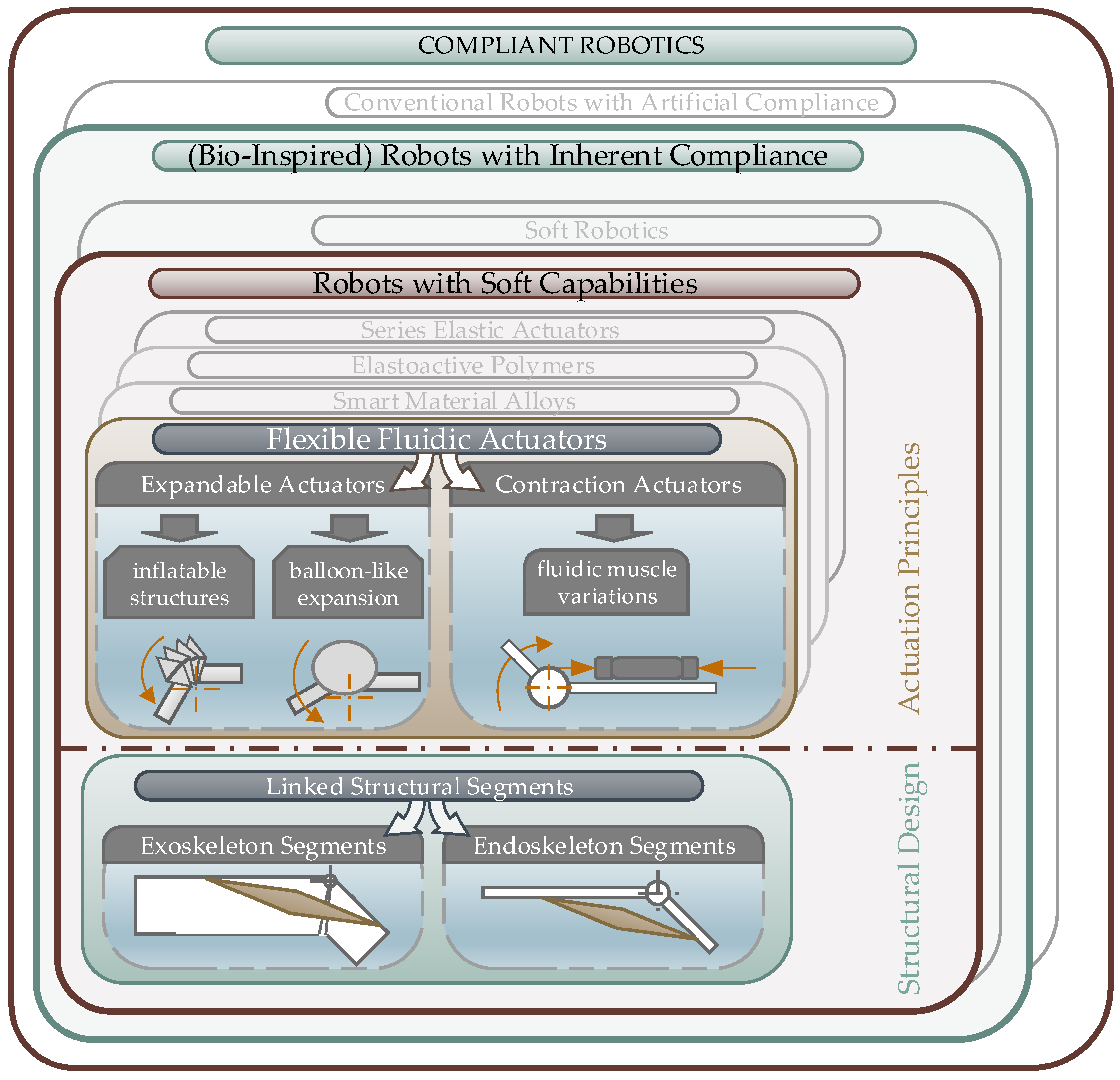
3.1.1. Bio-Inspired Robots with Soft Capabilities

The evaluation of the soft actuated robots shows that there are structural designs and actuation principles that are typical for these kind of robotic devices.
The bearing structure usually consists of segments connected by pivot, hinge, or spherical links [21], which form an endoskeleton [52,53] or exoskeleton [54,55]. Compliant actuators are situated upon the bearing structure. Usually, the location of the soft actuators is bio-inspired in agonist-antagonist arrangement [46]. Naturally soft materials and actuation elements typically show a highly nonlinear dynamic behavior, which makes accurate control a challenging task. But nevertheless, the interest in these actuators is gaining. Significant research is being done on inherent compliant actuation principles and therefore several fields have formed. Some sub-fields are defined around shape changing materials, like smart material alloys (SMAs [56,57,58]), electroactive polymers (EAPs [59,60]) or integrated series of electrically adjustable springs (SEAs [50,61]). But still most naturally compliant robots are actuated fluidically [46]. Therefore flexible materials are pressurized pneumatically [52,62,63,64] or hydraulically [65] to generate a shape deformation in order to operate the robotic joints.

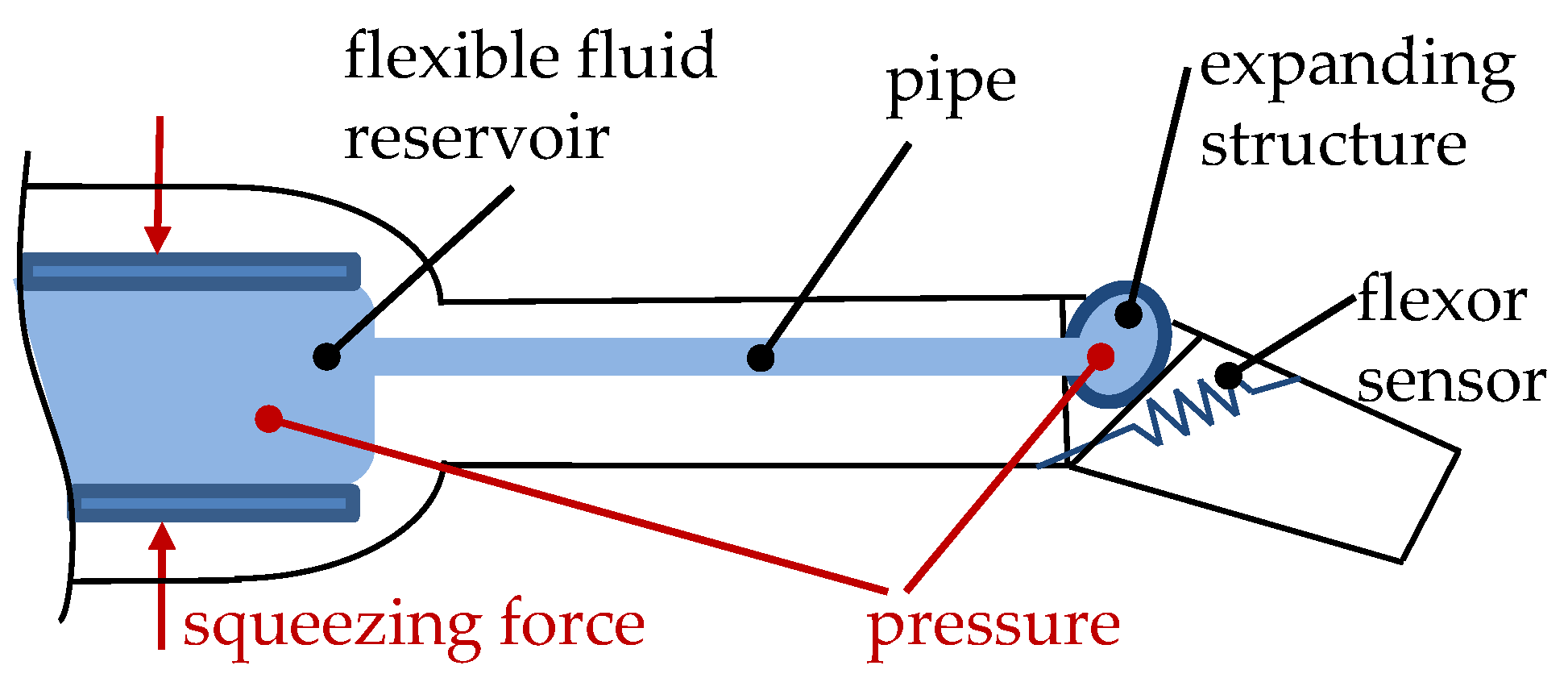
3.1.2. Flexible Fluidic Actuators

As detailed in Section 2.3, the biological spider uses fluidic expansion of inflatable joint membranes to extend the legs. Thus, this review focuses on the sub-field of fluidically actuated robotic devices, see Figure 6. To name some reasons for the common use of flexible fluidic actuation principles, we can list:
  • The availability of mediums (air/water),
  • Standardized periphery components like valves, pressure regulators and connections,
  • Natural compressibility of air,
  • New rapid prototyping methods to manufacture flexible materials [66,67],
  • No or low additional energy consumption for position holding with stop valves,
  • High energy efficiency [68],
  • Large deformation of the pressurized materials.
Today, fluidic, biomimetic, and compliant robotic actuators can be found in various areas of application: From micro-actuation systems for surgical tools and new industrial purposes [65] to medical and rehabilitation devices [2,3,69], or handling devices [66] and mobile robots [47,70].
Two types of flexible fluidic actuators can be distinguished according to the behavior of the actuator structure while pressurizing their inner volume:
  • Structural expansion to push the linked segments apart to generate a movement,
  • Structural contraction, which can be used to apply a retraction force between the linked segments.
Multiple individual and case-dependent designs can be found for the expansion structures. Typically, the expansion during pressurization shows inflatable deformations for bellow-like designs [52,63,67,71] or balloon-like deformations for bladder-like designs [72]. Contraction actuators are commonly known as pneumatic artificial muscles (PAMs) [73] or McKibben muscles [74,75]. Pressurizing these cylindrical structures leads to an expansion in radial dimension, but generates a contraction in the axial direction to transmit tension forces. The axial contraction can either be achieved through the combination of a rubber or silicon tube and an exterior meshed fiber braid to form a cylindrical shape [76,77] or through special pleating designs [78,79]. Pneumatic muscles are now commonly used to develop soft pneumatic devices for use in medical instruments [2] and rehabilitation devices [69,80,81], as well as for assistant robots [63,82]. Typical contraction rates are 20 percent of the free length and commercial pneumatic muscles are available from [83,84].

3.2. Bio-Inspired Actuators with Reference to the Spider Principle

In this study, the biomimetic actuators that are directly referred as being developed based on the spider leg joint mechanism are identified and discussed. Figure 7a–f gives an overview of these actuators. They are scattered in various fields of application, from micro-actuators to rehabilitation to mobile robot systems. But nevertheless, all of them clearly match the classification, shown in Figure 6.
First concept designs for biomimetic applications referring to the spider leg can be followed back to 1996 when Zentner (nee Bohmann) published the idea of a spider-inspired gripper [32]. In 1998, Schwörer et al. focused on miniaturizing the spider leg principle by developing a fluidic micro joint [72]—shown in Figure 7a—with a prototype of 1 mm diameter that reaches an angle of 41 degrees and a torque of 20 μNm at a pressure of 0.1 MPa. Possible applications for this micro technology are in surgery tools. Zentner et al. meanwhile continued their biomechanical research (see Figure 4 and [32]) and developed a pneumatic joint prototype for grasping tasks [85,86], which is shown in Figure 7b). The monolithic device is made from silicon rubber and can reach an angle of 90 degrees while pressurizing with up to 0.3 MPa. A pivot point is realized by an integral hinge due to the flattened backside. The retraction is passive, using the elasticity of the material. Conceivable applications are in medical and surgical tools or sensitive grasping tasks, due to size- and pressure-dependent torque.
The “smart stick” (Figure 7c) was developed by Menon and Lira [88,94] investigating various properties of the whole spider for their use in space applications. They focused on the principle of hydraulic extension and used a flexible tube (Ø 1 mm), which is placed perpendicular between spacing elements. Each joint element yields a deformation of up to 5 degrees while actuated with up to 1.2 MPa of hydraulic pressure. Several joints can be placed in a row to reach the desired rotational angle or end effector point. The closed fluid loop circuit illustrated in Figure 8 has not yet been fully described and therefore presents another research opportunity. Squeezing the body or one end of the tube leads to a volume shift and to a rotational movement of the joint, which is retracted by a passive mechanical spring [88].
Automatic hand prostheses [95] as well as an elbow orthosis [53,89] shown in (Figure 7d) were developed using the spider’s membrane inflation principle. Rotational bellows are placed on endoskeleton limbs. The reinforced bellows with sizes from 11 mm to 36 mm are operated with up to 1.0 MPa of air pressure. The retraction occurs by passive mechanical springs or by another bellow on the opposite side of the joint. Based on research in additive manufacturing processes, Becker developed a bellow actuator principle [90] made from selective laser sintered (SLS) materials which is shown in Figure 7e. A pneumatic spider robot using these bellow leg joints was built in 2011. In this application, the bellow actuators are designed with a diameter of 20 mm with five bellows in a row that are pressurized with up to 0.4 MPa; the retraction is passive due to the material stiffness. Figure 7f, shows an actuator developed by Landkammer et al. [92,96], in which the spider’s inflatable membrane extension principle is combined with active antagonistic muscular flexion as it is with biological spider legs. It is the only biomimetic actuator, which transfers the whole antagonistic biological function principle, including extension and flexion, into a technical application. Regarding the implementation, pneumatic muscles [83] are integrated inside pressurized exoskeletal parts connected by hinge joints. During movements, the exoskeleton with the inflatable asymmetric membrane is continuously pressurized with air up to 0.15 MPa to initialize the rotational extension. Furthermore, the pneumatic muscular flexors are supplied with air up to 0.8 MPa. The pressure difference to the exoskeleton environment effectively operates this contraction actuator. Thus, an antagonistic counterplay is produced. Regulating both pressure sources permits dynamic movements and the energy efficiency can be enhanced by a dynamic adjustment depending on external influences [97].
Due to nonlinear torque-angle characteristics and a lack of detailed torque data for some actuators and different available diameter sizes, it is hard to achieve a detailed torque comparison. Nevertheless, a chart for comparing the actuator torques and entire cross sections is illustrated in the bottom section of Figure 7.
Another point is the integrated sensory for detecting the angle position, which is essential for controlling the actuators movement while operating in robotic applications. Therefore, the “smart stick” (Figure 7c) uses a flexion sensor which not described in detail [88]. In comparison, the pneumatic bellow joint (Figure 7d) is equipped with a rotational hall encoder near the pivot point as depicted in Reference [12] and the biomimetic joint in Figure 7f uses a potentiometer which is connected between the two exoskeleton sections, as shown in Reference [97]. No description of position sensory concepts where found for the actuators (a), (b) and (e) in Figure 7.

4. Conclusions and Discussion

With spider leg joints, nature shows us an impressive example how lightweight design, powerful actuation, inherent compliance, and energy efficiency can go hand in hand. Therefore, it is a much-courted field of biological research. Many efforts have been made to gain biomechanical understanding of the principle, as its advantages are interesting for various technical applications. Nevertheless, we are far from completely understanding how the antagonistic biological principle inside the small legs works in detail. This is especially true for the dynamic behavior and the interactions between hemolymph extension and muscular flexion, as well as how they influence each other. Further research is necessary to draw conclusions on the energy efficiency of the system.
As stated above, the fundamental biological research has yielded the foundations for technical applications in various fields of robotic actuation. Especially the health sector and private or industrial assistant robotics provide a wide field of application for spider leg actuators, as is illustrated in Figure 7. This coincides with the trends of soft actuated robotics for safer human-robot-interaction through inherent compliance. Although much work has already taken place in the area of biomimetic robotics, this field of research promises enormous potential for future energy efficient and compliant actuators. By comparing the bio-inspired spider leg joints, it can be said that just a few of them are biomimetic developments and most of them have solely focused on the pneumatic or hydraulic extension. An exception to this can be seen in Figure 7f, where the combination of inflatable extension and active retraction is the goal. A more dynamic behavior is expected from this combination and furthermore a case-to-case adjustment of both pressure levels promises energy efficiency. The antagonistic system of the two nested principles also causes interaction effects due to the changing volumes of the muscle and the joint section, which makes it more complicated to control. Pressure variations similar to the biological pressure variations in actual spider legs can occur, if the actuation is hydraulic. Therefore, the technical application may also provide an opportunity to study the biological principle itself.

Acknowledgments

The authors would like to thank the Bavarian Environment Agency for financing the project “Development of an innovative spider robot with bio-inspired hydraulic actuator legs and an intuitive control concept” as part of the biomimetic initiative “bionicum”. Special thanks for cooperation to Jens Runge and Christian Wirkner from the Institute of Biosciences-Department of Zoology from the University of Rostock and to Hendrik Bargel from BioMat—Institute for Biomaterials from the University of Bayreuth.

Author Contributions

Rüdiger Hornfeck directed and guided this study. Stefan Landkammer and Florian Winter investigated the biological research done on the spider leg mechanism and classified the robotic actuation systems. Stefan Landkammer and Daniel Schneider identified and discussed the biomimetic joints related to the spider leg.

Conflicts of Interest

The authors declare no conflicts of interest.

References

  1. Finkemeyer, B. Moderne Zeiten Werden Modern; Kieler Prozessmanagementforum: Kiel, Germany, 2014. [Google Scholar]
  2. De Greef, A.; Lambert, P.; Delchambre, A. Towards flexible medical instruments: Review of flexible fluidic actuators. Precis. Eng. 2009, 33, 311–321. [Google Scholar] [CrossRef]
  3. Belforte, G.; Eula, G.; Ivanov, A.; Sirolli, S. Soft Pneumatic actuators for rehabilitation. Actuators 2014, 3, 84–105. [Google Scholar] [CrossRef]
  4. International Organization for Standardization (ISO). Robots and Robotic Devices—Safety Requirements for Industrial Robots—Collaborative Operation; ISO/TS 15066; ISO: Geneva, Switzerland, 2011. [Google Scholar]
  5. O’Neill, J.; Lu, J.; Dockter, R.; Kowalewski, T. Design of a stretchable, flexible smart skin sensor for robotic applications. In Proceedings of the ICRA2015, International Conference on Robotics and Automation, Seattle, WA, USA, 26–30 May 2015; IEEE: Piscataway, NJ, USA, 2015; pp. 624–629. [Google Scholar]
  6. Corrales, J.A. Safe Human-Robot Interaction Based on Multi-Sensor Fusion and Dexterous Manipulation Planning. Ph.D. Thesis, Universidad de Alicante, Alicante, Spain, 2011. [Google Scholar]
  7. Pedrocchi, N.; Vicentini, F.; Matteo, M.; Molinari, L. Safe human-robot cooperation in an industrial environment. Int. J. Adv. Robot. Syst. 2013, 27. [Google Scholar] [CrossRef]
  8. Iida, F.; Laschi, C. Soft robotics: Challenges and perspectives. Procedia Comput. Sci. 2011, 7, 99–102. [Google Scholar] [CrossRef]
  9. Gracia, E.; Arevalo, J.; Cestari, M.; Sanz-Merodio, D. On the Technological instantiation of a biomimetic leg concept for agile quadrupedal locomotion. J. Mech. Robot. 2015, 7, 031005. [Google Scholar] [CrossRef]
  10. Pescovitz, D. Robots That Show Their Softer Side. Bloomberg Buisnessweek, 2014. Available online: http://www.businessweek.com/articles/2014-08-21/soft-robotics-research-snuggle-against-the-machine (accessed on 1 March 2016).
  11. Kim, S.; Laschi, C.; Trimmer, B. Soft robotics: A bioinspired evolution in robotics. Trends Biotechnol. 2013, 31, 287–294. [Google Scholar] [PubMed]
  12. Gaiser, I.; Weigand, O.; Ivlev, O.; Andres, A.; Breitwieser, H.; Schulz, S.; Bretthauer, G. Compliant robotics and automation with flexible fluidic actuators and inflatable structures. In Smart Actuation and Sensing Systems—Recent Advances and Future Challenges; Berselli, G., Vertechy, R., Vassura, G., Eds.; INTECH Open Science: Morn Hill, UK, 2012; pp. 567–608. [Google Scholar]
  13. Toth, T.I.; Knops, S.; Daun-Gruhn, S. A neuromechanical model explaining forward and backward stepping in the stick insect. J. Neurophysiol. 2012, 107, 3267–3280. [Google Scholar] [PubMed]
  14. Schultz, J. Evolution of locomotion in Anarchida: The hydraulic pressure pump of the Giant Whipscorpion. J. Morphol. 1991, 210, 13–31. [Google Scholar] [CrossRef]
  15. Suter, R.B.; Wildman, H. Constraints on rowing locomotion on the water surface. J. Exp. Biol. 1999, 202, 2771–2785. [Google Scholar] [PubMed]
  16. Foelix, R. Biology of Spiders, 3rd ed.; Oxford University Press: Oxford, UK, 2011. [Google Scholar]
  17. Eggs, B.; Wolff, J.O.; Kuhn-Nentwig, L.; Gorb, S.N.; Nentwig, W.; Wright, J. Hunting without a web: How lycosoid spiders subdue their prey. Int. J. Behav. Biol. Ethol. 2015, 121, 1166–1177. [Google Scholar]
  18. Gasparetto, A.; Vidoni, R.; Seidl, T. Kinematic study of the spider locomotor system in a biomimetic perspective. In Proceedings of the IROS 2008, International Conference on Intelligent Robots and Systems (IROS), Nice, France, 22–26 September 2008; IEEE: Piscataway, NJ, USA, 2008. [Google Scholar]
  19. Weihmann, T.; Gunther, M.; Blickhan, R. Hydraulic leg extension is not necessarily the main drive in large spiders. J. Exp. Biol. 2012, 215, 578–583. [Google Scholar] [PubMed]
  20. Sens, J. Funktionelle Anatomie und Biomechanik der Laufbeine Einer Vogelspinne (Grammostola Spatulata F.O. Pickard-Cambridge). Ph.D. Thesis, Universität des Saarlandes, Saarbrücken, Germany, 2006. [Google Scholar]
  21. Bögelsack, G. On technomorphic modelling and classification of biological joints. Theory Biosci. 2000, 119, 104–121. [Google Scholar] [CrossRef]
  22. Blickhan, R.; Barth, F.G. Strains in the exoskeleton of spiders. J. Comp. Physiol. A 1985, 157, 115–147. [Google Scholar] [CrossRef]
  23. Huckstorf, K.; Kosok, G.; Seyfarth, E.-A.; Wirkner, C.S. The hemolymph vascular system in Cupiennius salei (Araneae: Ctenidae). Zool. Anz. J. Comp. Zool. 2013, 252, 76–87. [Google Scholar] [CrossRef]
  24. Barth, F.G. A Spider’s World—Senses and Behavior; Springer: Berlin, Germany; New York, NY, USA, 2002. [Google Scholar]
  25. Petrunkevitch, A. Contributions to our knowledge of the anatomy and relationships of spiders. Ann. Entomol. Soc. Am. 1909, 2, 11–20. [Google Scholar] [CrossRef]
  26. Brown, R.B. The musculature of Angelina Naevia. J. Morphol. 1939, 64, 115–166. [Google Scholar] [CrossRef]
  27. Ellis, C. The mechanism of extension in the legs of spiders. Biol. Bull. 1944, 86, 41–50. [Google Scholar] [CrossRef]
  28. Parry, A.; Brown, H. The hydraulic mechanism of the spider leg. J. Exp. Biol. 1959, 36, 423–433. [Google Scholar]
  29. Wilson, R.S. Some comments on the hydrostatic system of spiders (Chelicerata, Araneae). Z. Morphol. Tiere 1970, 68, 308–322. [Google Scholar] [CrossRef]
  30. Stewart, D.; Martin, A. Blood pressure in the tarantula, Dugesiella hentzi. J. Comp. Physiol. 1974, 88, 141–172. [Google Scholar] [CrossRef]
  31. Anderson, J.; Prestwich, K. The Fluid pressure pumps of spiders (Chelicerata, Araneae). Z. Morphol. Tiere 1975, 81, 257–277. [Google Scholar] [CrossRef]
  32. Bohmann, L.; Blickhan, R. Der hydraulische Mechanismus des Spinnenbeines und seine anwendung für technische probleme. Z. Angew. Math. Mech. 1996, 78, 87–96. [Google Scholar] [CrossRef]
  33. Zentner, L.; Petkun, S.; Blickhan, R. From the spider leg to a hydraulic device. Tech. Mech. 1999, 20, 21–29. [Google Scholar]
  34. Zentner, L. Untersuchung und Entwicklung Nachgiebiger Strukturen Basierend auf Innendruckbelasteten Röhren mit Stoffschlüssigen Gelenken, Habilitation; Technische Universität: Ilmenau, Germany, 2003. [Google Scholar]
  35. Zentner, L. Modelling and application of the hydraulic spider leg mechanism. In Spider Ecophysiology; Nentwig, W., Ed.; Springer: Heidelberg, Germany, 2013; pp. 451–462. [Google Scholar]
  36. Ruhland, M.; Rathmayer, W. Die Beinmuskulatur und ihre Innervation bei der Vogelspinne (Araneae, Aviculariidae). Zoomorphologie 1978, 89, 33–46. [Google Scholar] [CrossRef]
  37. Clarke, J. The comparative functional morphology of the leg joints and muscles of five spiders. Bull. Br. Arachnol. Soc. 1986, 7, 37–47. [Google Scholar]
  38. Siebert, T.; Weihmann, T.; Rode, C.; Blickhan, R. Cupiennius salei: Biomechanical properties of the tibia-metatarsus joint and its flexing muscles. J. Comp. Physiol. B 2010, 180, 199–209. [Google Scholar] [CrossRef] [PubMed]
  39. Runge, J.; Landkammer, S.; Valek, R.; Wirkner, C.S. 3D functional morphology of the femur-patella joint in Cupiennius salei (Araneae; Ctenidae). In Proceedings of the 28th European Congress of Arachnology, Turin, Italy, 24–29 August 2014.
  40. Manton, S.M.; Harding, J.P. Hydrostatic pressure and leg extension in arthropods, with special reference to arachnids. Ann. Mag. Nat. Hist. 1958, 1, 161–182. [Google Scholar] [CrossRef]
  41. Kropf, C. Hydraulic system of locomotion. In Spider Ecophysiology; Nentwig, W., Ed.; Springer: Heidelberg, Germany, 2013; pp. 43–56. [Google Scholar]
  42. Prestwich, K.N. The constraints on maximal activity in spiders. J. Comp. Physiol. B 1988, 158, 437–447. [Google Scholar] [CrossRef]
  43. Sensenig, A.T. Mechanics of cuticular elastic energy storage in leg joints lacking extensor muscles in arachnids. J. Exp. Biol. 2003, 206, 771–784. [Google Scholar] [CrossRef] [PubMed]
  44. Trivedi, D.; Rahn, C.D.; Kier, W.M.; Walker, I.D. Soft robotics: Biological inspiration, state of the art, and future research. Appl. Bionics Biomech. 2008, 5, 99–117. [Google Scholar] [CrossRef]
  45. VDI—Gesellschaft Technologies of Life Science (TLS). Biomimetics—Conception and Strategy, Difference between Biomimetic and Conventional Methods/Products; VDI 6220, 07.080; Beuth: Düsseldorf, Germany, 2012. [Google Scholar]
  46. Rus, D.; Tolley, M.T. Design, fabrication and control of soft robots. Nature 2015, 521, 467–475. [Google Scholar] [CrossRef] [PubMed]
  47. Marchese, A.D.; Katzschmann, R.K.; Rus, D. A recipe for soft fluidic elastomer robots. Soft Robot. 2015, 2, 7–25. [Google Scholar] [CrossRef]
  48. Cianchetti, M.; Arienti, A.; Follador, M.; Mazzolai, B.; Dario, P.; Laschi, C. Design concept and validation of a robotic arm inspired by the octopus. Mater. Sci. Eng. C 2011, 31, 1230–1239. [Google Scholar] [CrossRef]
  49. Mao, S.; Dong, E.; Xu, M.; Jin, H.; Li, F.; Yang, J. Design and development of starfisch-like robot: Soft bionic platform with multi-motion using SMA actuators. In Proceedings of the ROBIO 2013, International Conference on Robotics and Biomimetics, Shenzhen, China, 12–14 December 2013; IEEE: Piscataway, NJ, USA, 2013. [Google Scholar]
  50. Haegele, M.; Maufroy, C.; Kraus, W.; Siee, M.; Breuninger, J. Musculoskeletal robots and wearable devices on the basis of cable-driven actuators. In Soft Robotics; Verl, A., Albu-Schäffer, A., Brock, O., Raatz, A., Eds.; Springer Verlag: Heidelberg, Germany, 2015; pp. 42–53. [Google Scholar]
  51. Rosendo, A.; Liu, X.; Shimizu, M.; Hosoda, K. Stretch reflex improves rolling stability during hopping of a decerebrate biped system. Bioinspir. Biomim. 2015, 10. [Google Scholar] [CrossRef] [PubMed]
  52. Ivlev, O. Soft fluidic actuators of rotary type for safe physical human-machine interaction. In Proceedings of the ICORR2009, IEEE 11th International Conference on Rehabilitation Robotics (ICORR), Kyoto, Japan, 23–26 June 2009; IEEE: Piscataway, NJ, USA, 2009. [Google Scholar]
  53. Pylatiuk, C.; Kargov, A.; Gaiser, I.; Schulz, S.; Bretthauer, G. Design of a flexible fluidic actuation system for a hybrid elbow orthosis. In Proceedings of the ICORR2009, IEEE 11th International Conference on Rehabilitation Robotics (ICORR), Kyoto, Japan, 23–26 June 2009; IEEE: Piscataway, NJ, USA, 2009. [Google Scholar]
  54. Van der Linde, R.; Caarls, J.; Menon, C.; Verhoef, J. Biological Inspired Joints for Innovative Articulation Concepts; ESA Report; TU Delft: Delft, The Netherlands, 2006. [Google Scholar]
  55. Yatsko, J.S.; Yatsko, D.E. Fluid-Powerd Mechanical Actuator and Method for Controlling. U.S. Patent 7,100,491, 5 September 2006. [Google Scholar]
  56. Guo, Z.; Pan, Y.; Wee, L.B.; Yu, H. Design and control of a novel compliant differential shape memory alloy actuator. Sens. Actuators A Phys. 2015, 225, 71–80. [Google Scholar] [CrossRef]
  57. Coral, W.; Rossi, C.; Martin, I. Bio-inspired morphing caudal fin using shape memory alloy composites for a fish-like robot. In Proceedings of the ICINCO 2015, 12th International Conference on Informatics in Control, Automation and Robotics, Colmar, France, 21–23 July 2015; pp. 336–343.
  58. Rodrigue, H.; Bhandari, B.; Han, M.-W.; Ahn, S.-H. A shape memory alloy-based soft morphing actuator capable of pure twisting motion. J. Intell. Mater. Syst. Struct. 2015, 26, 1071–1078. [Google Scholar] [CrossRef]
  59. Brochu, P.; Pei, Q. Dielectric Elastomers for actuators and artificial muscles. In Electroactivity in Polymeric Materials; Rasmussen, L., Ed.; Springer: New York, NY, USA, 2012; pp. 1–56. [Google Scholar]
  60. Hager, M.D.; Bode, S.; Weber, C.; Schubert, U.S. Shape memory polymers—Past, present and future developments. Prog. Polym. Sci. 2015, 49, 3–33. [Google Scholar] [CrossRef]
  61. Vallery, H.; Veneman, J.; van Asseldonk, E.; Ekkelenkamp, R.; Buss, M.; van der Kooij, H. Compliant actuation of rehabilitation robots. IEEE Robot. Autom. Mag. 2008, 15, 60–69. [Google Scholar] [CrossRef]
  62. Baiden, D.; Wilkening, A.; Ivlev, O. Safety and handling concept for assistive robotic devices with pneumatic rotary soft-actuators. In Proceedings of the AIM 2011, International Conference on Advanced Intelligent Mechatronics, Budapest, Hungary, 3–7 July 2011; IEEE: Piscataway, NJ, USA, 2011; pp. 754–759. [Google Scholar]
  63. Taghia, J.; Wilkening, A.; Ivlev, O. Position control of soft-robots with rotary-type pneumatic actuators. In Proceedings of the ROBOTIK, 7th German Conference on Robotics, Munich, Germany, 21–22 May 2012; pp. 399–404.
  64. Andrikopoulos, G.; Nikolakopoulos, G.; Manesis, S. A survey on applications of pneumatic artificial muscles. In Proceedings of the 19th Mediterranean Conference on Control & Automation (MED), Corfu, Greece, 20–23 June 2011; IEEE: Piscataway, NJ, USA, 2011; pp. 1439–1446. [Google Scholar]
  65. De Volder, M.; Reynaerts, D. Pneumatic and hydraulic microactuators: A review. J. Micromech. Microeng. 2010, 20. [Google Scholar] [CrossRef]
  66. Blanes, C.; Mellado, M.; Beltran, P. Novel additive manufacturing pneumatic actuators and mechanisms for food handling grippers. Actuators 2014, 3, 205–225. [Google Scholar] [CrossRef]
  67. Rost, A.; Schadle, S. The SLS-generated soft robotic hand—An integrated approach using additive manufacturing and reinforcement learning. In Proceedings of the 12th International Conference on Machine Learning and Applications (ICMLA), Miami, FL, USA, 4–7 December 2013; IEEE: Piscataway, NJ, USA, 2013; pp. 215–220. [Google Scholar]
  68. Jani, J.M.; Leary, M.; Subic, A.; Gibson, M.A. A review of shape memory alloy research, applications and opportunities. Mater. Des. 2014, 56, 1078–1113. [Google Scholar] [CrossRef]
  69. Sawicki, G.S.; Ferris, D.P. A pneumatically powered knee-ankle-foot orthosis (KAFO) with myoelectric activation and inhibition. J. Neuro. Eng. Rehabil. 2009, 6. [Google Scholar] [CrossRef] [PubMed]
  70. Schulz, S.; Pylatiuk, C.; Kargov, A.; Oberle, R.; Klosek, H.; Bretthauer, G. Biologically inspired fluidically driven robots. In Proceedings of the CLAWAR 2005—8th International Conference on Climbing and Walking Robots, London, UK; Springer: Berlin/Heidelberg, Germany, 2006; pp. 97–104. [Google Scholar]
  71. Kargov, A.; Werner, T.; Pylatiuk, C.; Schulz, S. Development of a miniaturised hydraulic actuation system for artificial hands. Sens. Actuators A Phys. 2008, 141, 548–557. [Google Scholar] [CrossRef]
  72. Schwörer, M.; Kohl, M.; Menz, W. Fluidic microjoints based on spider legs. In Proceedings of the Actuator 98, 6th International Conference on New Actuators, Bremen, Germany, 17–19 June 1998; Messe Bremen GmbH: Bremen, Germany, 1998; pp. 103–106. [Google Scholar]
  73. Daerden, F.; Lefeber, D. Pneumatic artificial muscles: Actuators for robotics and automation. Eur. J. Mech. Environ. Eng. 2000, 47, 10–21. [Google Scholar]
  74. Chou, C.-P.; Hannaford, B. Static and dynamic characteristics of McKibben pneumatic artificial muscles. In Proceedings of the ICRA 1994, IEEE International Conference on Robotics and Automation (ICRA), San Diego, CA, USA, 8–13 May 1994; IEEE Computer Society Press: Los Alamitos, CA, USA, 1994; pp. 281–286. [Google Scholar]
  75. Tondu, B.; Lopez, P. Modeling and control of McKibben artificial muscle robot actuators. IEEE Control Syst. Mag. 2000, 20, 15–38. [Google Scholar] [CrossRef]
  76. Tondu, B. Modelling of the McKibben artificial muscle: A review. J. Intell. Mater. Syst. Struct. 2012, 23, 225–253. [Google Scholar] [CrossRef]
  77. Chou, C.-P.; Hannaford, M. Measurement and modeling of McKibben pneumatic artificial muscles. IEEE Trans. Robot. Autom. 1996, 12, 90–102. [Google Scholar] [CrossRef]
  78. Immega, G.; Kukolj, M. Axially Contractable Actuator. U.S. Patent 4,939,982, 10 July 1990. [Google Scholar]
  79. Daerden, F.; Lefeber, D.; Verrelst, R. Pleated pneumatic artificial muscles: Compliant robotic actuators. In Proceedings of the ICIRS 2011, International Conference on Intelligent Robots and Systems, Maui, HI, USA, 29 September–3 October 2001; IEEE: Piscataway, NJ, USA, 2001; pp. 1958–1963. [Google Scholar]
  80. Waycaster, G. Design of a Powered Above Knee Prothesis Using Pneumatic Artificial Muscles. Master’s Thesis, University of Alabama, Tuscaloosa, AL, USA, 2010. [Google Scholar]
  81. Tsagarakis, N.G.; Caldwell, D.G. Improved modelling and assessment of pneumatic muscle actuators. In Proceedings of the ICRA 2000, International Conference on Robotics and Automation (ICRA), San Francisco, CA, USA, 24–28 April 2000; IEEE Robotics and Automation Society: Piscataway, NJ, USA, 2000; pp. 3641–3646. [Google Scholar]
  82. Jordan, M.; Pietrusky, D.; Mihajlov, M.; Ivlev, O. Precise Position and trajectory control of pneumatic soft-actuators for assistance robots and motion therapy devices. In Proceedings of the ICORR2009, IEEE 11th International Conference on Rehabilitation Robotics (ICORR), Kyoto, Japan, 23–26 June 2009; IEEE: Piscataway, NJ, USA, 2009; pp. 663–668. [Google Scholar]
  83. Fluidic Muscle DMSP/MAS-Product-Catalogue, Festo GmbH. Available online: http://www.festo.com/cat/de_de/data/doc_de/PDF/DE/DMSP-MAS_DE.PDF (accessed on 18 February 2014).
  84. Shadow Air Muscles-Product-Catalogue, Shadow Robot Company. Available online: http://www.shadowrobot.com/products/air-muscles/ (accessed on 18 February 2014).
  85. Böhm, V.; Zentner, L. Stoffschlüssige Gelenke nach biologischem Vorbild. In Proceedings of the Wissenschaftliche Mitteilungen der 14. Frühlingsakademie, München, Germany, 30 April–5 May 2002; pp. 19–27.
  86. Zentner, L. Fluidisch Angetriebenes Stoffschlüssiges Gelenkelement. Deutsches Patent TU Ilmenau, DE000010316959A1, 12 April 2003. [Google Scholar]
  87. Zentner, L.; Böhm, V. On the mechanical compliance of technical systems. In Mechanical Engineering; Gokcek, M., Ed.; INTECH Open Science: Morn Hill, UK, 2012; pp. 341–352. [Google Scholar]
  88. Menon, C.; Lira, C. Active articulation for future space applications inspired by the hydraulic system of spiders. Bioinspir. Biomim. 2006, 1, 52–61. [Google Scholar] [CrossRef] [PubMed]
  89. Schulz, S. Fluid Actuator. Forschungszentrum Karlsruhe. European Patent EP 1,519,055B1, 8 September 2004. [Google Scholar]
  90. Breuninger, J.; Becker, R.; Wolf, A.; Rommel, S.; Verl, A. Generative Fertigung mit Kunststoffen-Konzeption und Konstruktion für Selektives Lasersintern; Springer: Berlin/Heidelberg, Germany, 2013. [Google Scholar]
  91. Becker, R.; Ondratschek, K. International Patent—Self-Propelling Platform. World Patent WO002012159737A1, 29 November 2012. [Google Scholar]
  92. Landkammer, S.; Hornfeck, R. A novel bio-inspired fluidic actuator for robotic applications. In Proceedings of the ICAST2014, 25th International Conference on Adaptive Structures and Technologies, The Hague, The Netherlands, 6–8 October 2014.
  93. Landkammer, S.; Hornfeck, R. Drehantrieb. Deutsches Patent, Technische Hochschule Nürnberg—Georg Simon Ohm. German Patent DE 10,2013,114,660B4, 20 December 2013. [Google Scholar]
  94. Menon, C.; Lira, C. Spider-Inspired embedded actuator for space applications. In Proceedings of the AISB 06, Adaptation in Artificial and Biological Systems, Bristol, UK, 3–6 April 2006.
  95. Schulz, S.; Pylatiuk, C.; Bretthauer, G. A new ultralight anthropomorphic hand. In Proceedings of the ICRA2001, International Conference on Robotics and Automation, Seoul, Korea, 21–26 May 2001; IEEE: Piscataway, NJ, USA, 2001; pp. 2437–2441. [Google Scholar]
  96. Hornfeck, R.; Landkammer, S. Drehantrieb. European Patent Application, Technische Hochschule Nürnberg Georg Simon Ohm. European Patent EP 2,902,642,A1, 12 December 2014. [Google Scholar]
  97. Landkammer, S.; Schneider, D.; Winter, F.; Heß, P.; Hornfeck, R. Static modeling of an antagonistic pneumatic actuator for robotic applications. In Proceedings of the ECMSM2015, IEEE Electronics, Control, Measurement, Signals and their Application to Mechatronics (ECMSM2015), Liberec, Czech Republic, 22–24 June 2015; IEEE: Piscataway, NJ, USA, 2015. [Google Scholar]
Figure 1. Cross section view of a tibial segment of a spider leg. Sketches according to [24].
Robotics 05 00015 g001
Figure 2. Mechanical membrane design of a tibia-metatarsus joint [22]. Sketches according to [24] (a) Membrane inflation with bellow-like design; (b) Membrane stretching with isotropic structure.
Robotics 05 00015 g002
Figure 3. Images showing spider joint membranes: (a) Microscope images (Microscope recordings in cooperation with Dr. Helmuth Mägdefrau, Tiergarten Nuremberg and Hendrik Bargel, University of Bayreuth, BioMat—Institute of Biomaterials) structure of a Grammostola Rosea; (b) SEM images of a Lasidora Parahybana; (c) Reverse-engineered microcomputed tomography (Micro CT scans and reverse engineering in cooperation with Jens Runge and Dr. Christian Wirkner, University of Rostock, Institute of Biosciences, Department of Zoology) of a Cupiennius Salei.
Robotics 05 00015 g003
Figure 4. Schematic model for mathematical modelling of the leg joint extension [35]. Sketches according to [32].
Robotics 05 00015 g004
Figure 5. Multibody model to simulate the joint angle movement due to muscular displacement.
Robotics 05 00015 g005
Figure 6. Classification of fluidic joint actuators with soft capabilities.
Robotics 05 00015 g006
Figure 7. Overview of bio-inspired actuators related to the spider leg principle. References: (a) [72]; (b) [85,86,87]; (c) [88]; (d) [53,89]; (e) [90,91]; (f) [92,93].
Robotics 05 00015 g007
Figure 8. Closed fluidic loop joint extension based on the spider principle [88]. Sketch according to [94].
Robotics 05 00015 g008

