The Thorvald II Agricultural Robotic System

Faculty of Science and Technology, Norwegian University of Life Sciences, Ås, 1432, Norway
*
Author to whom correspondence should be addressed.
Robotics 2017, 6(4), 24; https://doi.org/10.3390/robotics6040024
Submission received: 1 September 2017
/
Revised: 22 September 2017
/
Accepted: 25 September 2017
/
Published: 30 September 2017
(This article belongs to the Special Issue Agriculture Robotics)
Abstract
:This paper presents a novel and modular approach to agricultural robots. Food production is highly diverse in several aspects. Even farms that grow the same crops may differ in topology, infrastructure, production method, and so on. Modular robots help us adapt to this diversity, as they can quickly be configured for various farm environments. The robots presented in this paper are hardware modular in the sense that they can be reconfigured to obtain the necessary physical properties to operate in different production systems—such as tunnels, greenhouses and open fields—and their mechanical properties can be adapted to adjust for track width, power requirements, ground clearance, load capacity, and so on. The robot’s software is generalizing to work with the great variation of robot designs that can be realized by assembling hardware modules in different configurations. The paper presents several novel ideas for agricultural robotics, as well as extensive field trials of several different versions of the Thorvald II platform.
1. Introduction
Agricultural robots are to operate on farms with very different infrastructure and operating conditions. One way to make robots a viable option for farmers—both economically and from a practical point of view—is to develop robotic systems that are capable of operating in all of these operation environments. This would lead to several benefits. As an example, we would see reduced hardware costs as the same robots can operate on many farms. We would also expect extensive learning across several different areas as more data will be available from which to learn.
Farms are different in nature. First of all, they produce different types of food that require different machinery and a wide variety of production methods. In addition, farms greatly differ in size. In higher-income countries, for example, more than 30% of all farms are smaller than 1 ha, while more than 40% of the agricultural land is found on farms that are larger than 500 ha [1]. This illustrates the huge variations in size. The topography of the farmland is another factor adding to this natural variability of farms. In addition, we have different cultures and differences between countries and regions.
One of the problems with modern farming is the use of heavy equipment in the farm fields. The large weight of modern tractors causes soil compaction, which has several negative consequences, among them lower yields and more extensive flooding [2,3]. Ideally, farm machines should therefore be lightweight. This is made possible by the introduction of lightweight mobile robots to farms. As robots can work autonomously without the need of a driver for each machine, several smaller robots can be used to replace each large tractor, while keeping production at the same level. In this sense, novel software that results in completely autonomous robots is essential for making these lightweight robots a viable alternative to heavy machinery.
In the same way that the tractor has become the de facto standard in agricultural machinery, there is a need for a robotic system that can serve as a generic tool carrier across several different production methods. In this paper, we present the Thorvald II platform, which is a hardware and software modular robot designed to carry any tool and operate in any type of farmland.
1.1. Current State-of-The-Art
Several agricultural robots have emerged over the last few years. One of the earliest robots to appear was the German BoniRob. This robot was initially developed by AMAZONEN-WERKE together with the Osnabrück University of Applied Sciences, Robert Bosch GmbH and other partners, and is now a part of Deepfield Robotics, a Bosch start-up company. It was initially developed for phenotyping [4], but several other application modules (“apps”) have been developed for the robot through the years, among them a precision spraying app and a penetrometer app [5].
Various universities have developed their own robots. One example is the University of Sydney, Australia, where multiple robots have been developed. Among the best known is the Ladybird [6] and, later, also the Rippa robot, which has been used for, amongst other things, weed destruction. Another example of a university-developed agricultural robot is the multi-purpose SRFV from Queensland University of Technology, Australia [7]. There are also some interesting projects on the software side, such as FroboMind [8], which is an open software platform for field robots that aims to encourage and facilitate collaboration between research groups.
Companies that work on commercial robots exists. For the open field, there is the ANATIS from Carré, the Robotti from AGROINTELLI and Asterix from Adigo [9]. Ecorobotix is developing a robot for autonomous weeding, while Naïo technologies has developed the robots OZ, TED and DINO. Other robots are designed for greenhouses. One example is the fully-automatic S55 spray robot by Wanjet, Sweden.
The robots described above make up a representative subset of existing technology, although there are many other robots and projects that could have been mentioned.
The authors gained their own experience with agricultural robots through the development of Thorvald I [10], which started as a Master’s project at the Norwegian University of Life Sciences and has since developed into the robotic system presented in this paper.
What is common for the robots above, including Thorvald I, is their fairly fixed physical appearance. Although some of the robots can change certain parameters, BoniRob can for instance change its track width, there exists (to the author’s knowledge) no truly modular system for creating custom agricultural robots. Thorvald II aims to be this system.
1.2. Hardware and Software Modularity
The main motivation behind the Thorvald II platform is to develop a completely modular platform both on the hardware and the software side.
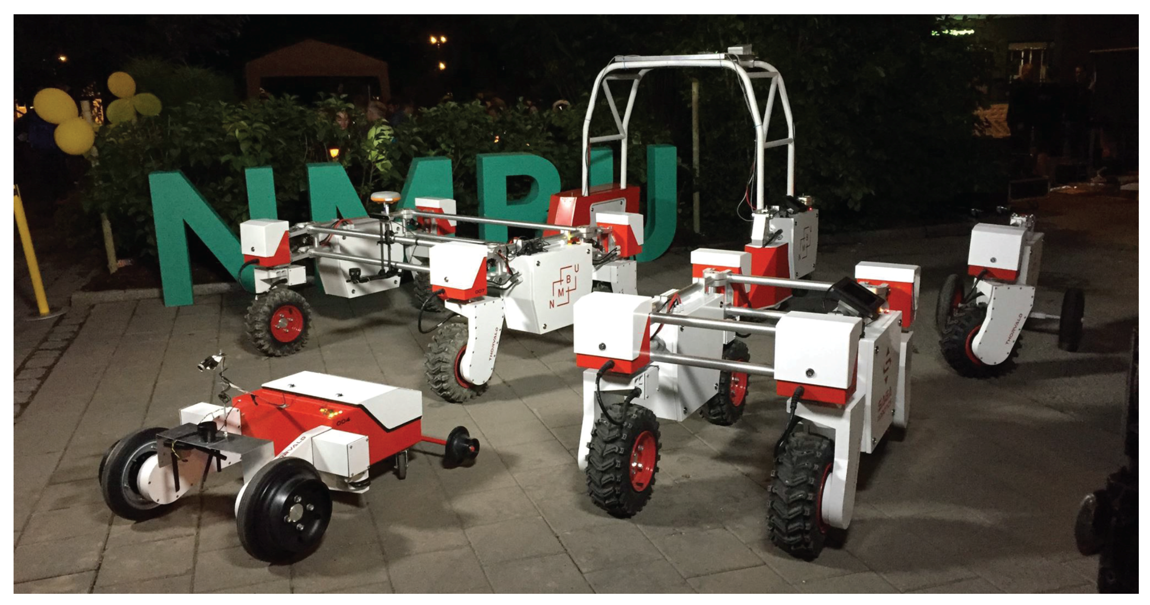
This paper will present a complete description of the hardware part and describe in detail how the robot presented is modular in several aspects when it comes to the mechanical design. By hardware modularity, we mean a robot that consists of standard modules and that with very simple operations can be reconfigured to work in a wide variety of environments. We show that the proposed robot can be designed to work in greenhouses and polytunnels, and to perform both energy-demanding and surveillance tasks in the open field. These robots are very different in their mechanical design, but all consist of the same modules. A few examples are shown in Figure 1.
We will also show our first developments in making the robot software modular. This is a continuous process, and much work is yet to be done to obtain a fully-modular robot in this sense. By software modularity, we mean an operation system that, together with the hardware modularity, allows the programmer to focus on the overall task that the robot is to perform and not having to worry about where the robot is to operate or under what conditions. This is automatically taken care of by the modular software. In this way, the goal is to have a robot that can be controlled independently of whether it is to operate in a greenhouse or an open field, or whether the crop is wheat or strawberry.
2. Materials and Methods
2.1. Module Design
The Thorvald II robotic system consists of several modules that can be combined in different ways to create vastly different robot designs. Modules connect through simple mechanical and electrical interfaces, and assembling a robot from modules can be done with only simple hand tools. Not all modules are critical for completing a functioning robot. Some modules exist merely for improving properties like traction or to make the robot easier to work with by, for example, simplifying sensor interfacing. The different robot modules are explained in more detail below.
2.1.1. Robot Frame
Different agricultural environments and applications may require robots of different widths, heights and lengths, or different frame stiffness and lifting capabilities. Even farms that grow the same kind of crop may require different robots due to dissimilarities in existing infrastructure.
To accommodate the variation of needs that may occur, it is important to include a great deal of customizability in the frame design. This is achieved by constructing the robot’s frame from aluminum tubes that are held together by specially-designed clamps. Clamps and brackets are also used to connect modules to the frame and, in some cases, to each other. Relevant modules share the same mechanical interface, e.g., a steering module may connect to the robot’s frame via a suspension module, or it may just as easily be connected directly to the frame in cases where a suspension module is not needed.
With the Thorvald II system, creating a robot with custom geometry is a matter of cutting aluminum tubes to the correct lengths and clamping them together. The robot’s frame may easily be made stiffer by clamping extra members to the frame, or more flexible by omitting frame members. A stiffer frame may carry more load, whilst a more flexible frame will increase the robot’s ability to keep wheels in connection with the ground.
All in all, the frame is in itself of low complexity. In fact, the Thorvald system’s ease of customization is made possible by containing complexity within modules. This means that completely custom frames may be achieved by simple means, also the ones that are not based on the above mentioned clamp and tube system.
2.1.2. Battery Enclosure
The battery enclosure can hold one single 70 Ah, or up to two 35 Ah, 48 V lithium batteries. It also contains space for electronics and a computer. A robot only needs one such module to operate, but more modules can be connected in parallel to increase the robot’s range. In the case where more than one module is used, one of the modules will be the “main battery enclosure”. Additional enclosures are called “sister battery enclosures”. The main battery enclosure module holds the robot’s main computer and a custom circuit board for managing power circuits, as well as for power-up and shutdown of the robot. The module serves as a connection point for the robot’s CAN (Controller Area Network), which is used for communicating with motor controllers. The main battery enclosure has a built-in audio amplifier that can drive up to two speakers, mounted either in one single or two separate battery enclosures. The module has a key switch for switching power to the main battery enclosure board. If this switch is in the off position, nothing can be turned on. A single pushbutton next to the key switch can be used to turn the computer, sensor and motor power buses on and off. Three light emitting diodes (LED) indicate whether the ignition, motor or computer power is switched on. The main battery enclosure can also be fitted with a waterproof touch screen if this is needed for human interaction.
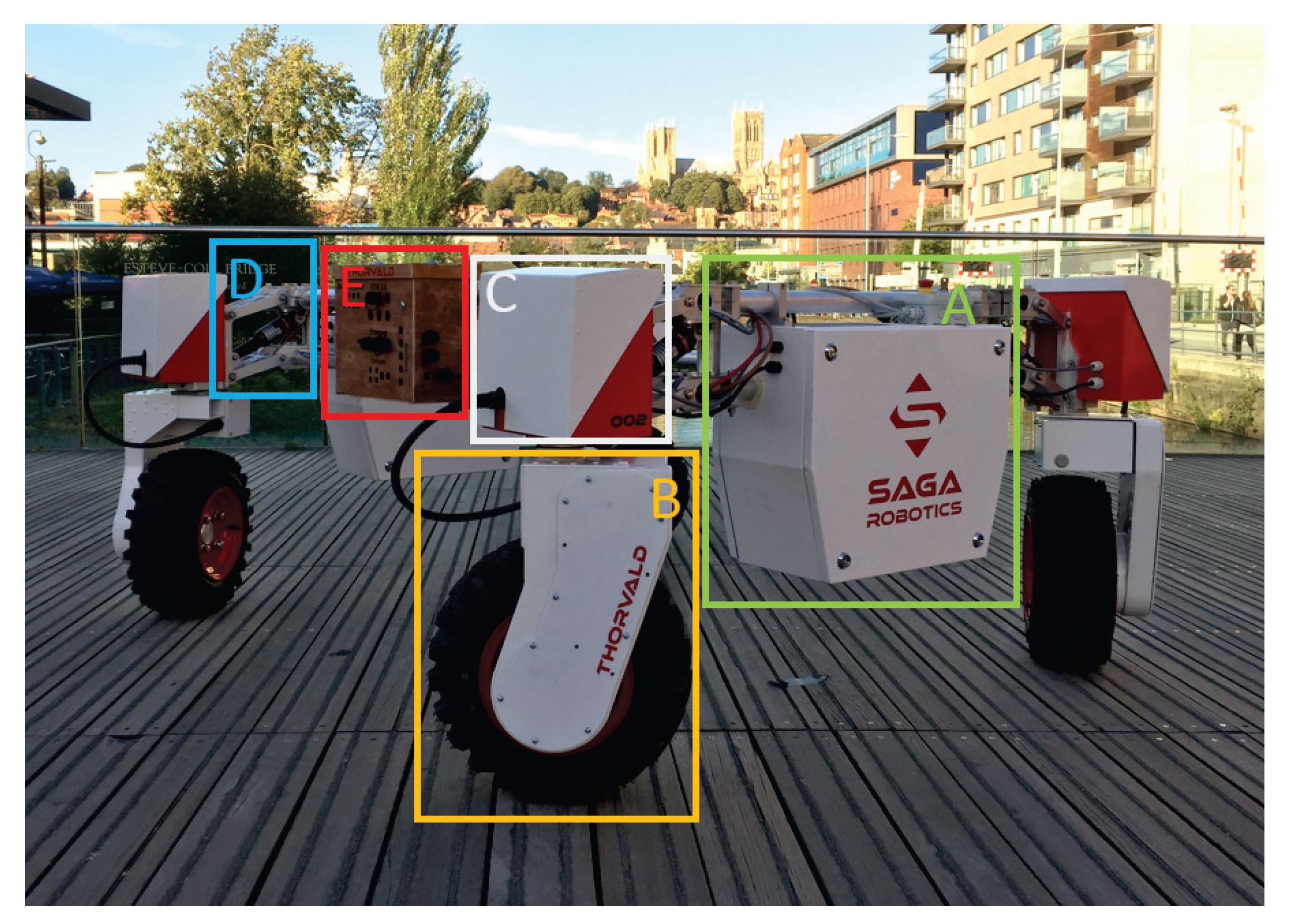
Sister battery enclosures are basically the same as the main enclosure, but will by default contain less components. A sister battery enclosure links to the main enclosure (or another sister enclosure) through one simple connector for communication and necessary low current circuits and two high current wires for motor power (in the case where the sister enclosure serves modules containing motors). Battery enclosures hold the necessary components for distributing power and CAN communication to other modules. By default, all battery enclosure modules are designed to serve three other modules with motor power and CAN communication. Battery enclosure modules can be fitted with emergency stop buttons for cutting the contactor on the motor power bus. Resetting a pressed emergency stop button is not enough to restore motor power. For this, the robot must receive a command to reengage the motor bus contactor. An example of a battery enclosure is shown in Figure 2.
2.1.3. Drive Module
One or more drive modules are used to propel the robot. It houses a 500 W electric brushless DC motor that is connected to a two-stage transmission with a wheel on the output. The transmission consists of a synchronous belt drive into an in-wheel planetary gearbox. The motor has built-in Hall effect sensors and is fitted with a 1024 pulse per revolution incremental rotary encoder. Only one cable exits in the module. This cable contains Hall and encoder signals and power, as well as the three power phases of the motor. The cable connects to a steering module, or in the case of a differential drive configuration, directly to a battery enclosure or to a separate motor-controller module.
The initial Thorvald II prototype was designed to carry a payload of 200 kg divided on its four drive modules. Since then, the drive module design has been greatly improved, and now, each single drive module is designed to carry 2.5 kN. This includes a safety factor of six from the static analysis to account for dynamic load. An example of a drive module is shown in Figure 2.
2.1.4. Steering Module
The drive module can be connected to a steering module if the robot requires drive modules to rotate in the horizontal plane. The steering module houses an electric brushless DC motor connected to a two-stage transmission with a flange for connecting the drive module on the output. The motor has built-in Hall effect sensors and is fitted with a 1024 pulse per rev incremental rotary encoder. As the encoder is incremental, it is necessary to perform a homing sequence at power-up. For this, an inductive sensor is used together with a metal reference on the steering shaft. The steering module also houses a two-channel motor controller, which connects to the robot’s CAN and controls the module’s own motor and the motor of the connected drive module. The output shaft of the steering module is programmed to allow degree rotation, which means that several configurations using this module, like the robot in Figure 2, can drive both forward and sideways with high maneuverability. The steering module can be connected directly to the robot’s frame or optionally to a suspension module.
2.1.5. Suspension Module
A suspension module can be connected between the robot’s frame and a steering module, or to a bracket on a drive module in the case of a differential drive robot. The module is optional, but will increase the robot’s ability to keep the wheel in contact with the ground. It will also help with absorbing shocks. The module holds an adjustable gas spring, oil dampened shock absorber and allows travel in the vertical direction. An example of a suspension module is shown in Figure 2.
2.1.6. Passive Wheel Modules
In some cases, there is no need for the robot to have all-wheel drive. In these cases, passive wheel modules are used for supporting the robot. Passive wheel modules are far less complex compared to their active counterpart (drive modules) and are naturally less costly to make. Various passive wheel modules have been created. Examples are caster wheels on differential drive robots and dual support wheels in the case of a 1WD, 1WS tricycle robot.
2.1.7. Modules for Sensors
Figure 2 shows a robot with a prototype of a module for housing computers, Ethernet switches, USB hubs, CAN connectivity, regulated DCDC converters, and so on. Sensors connect to the module through waterproof connectors and cable glands. On robots with two battery enclosures, there is space for computers and sensor-related circuit boards in the sister battery enclosure, and there may therefore not be a need for a dedicated module.
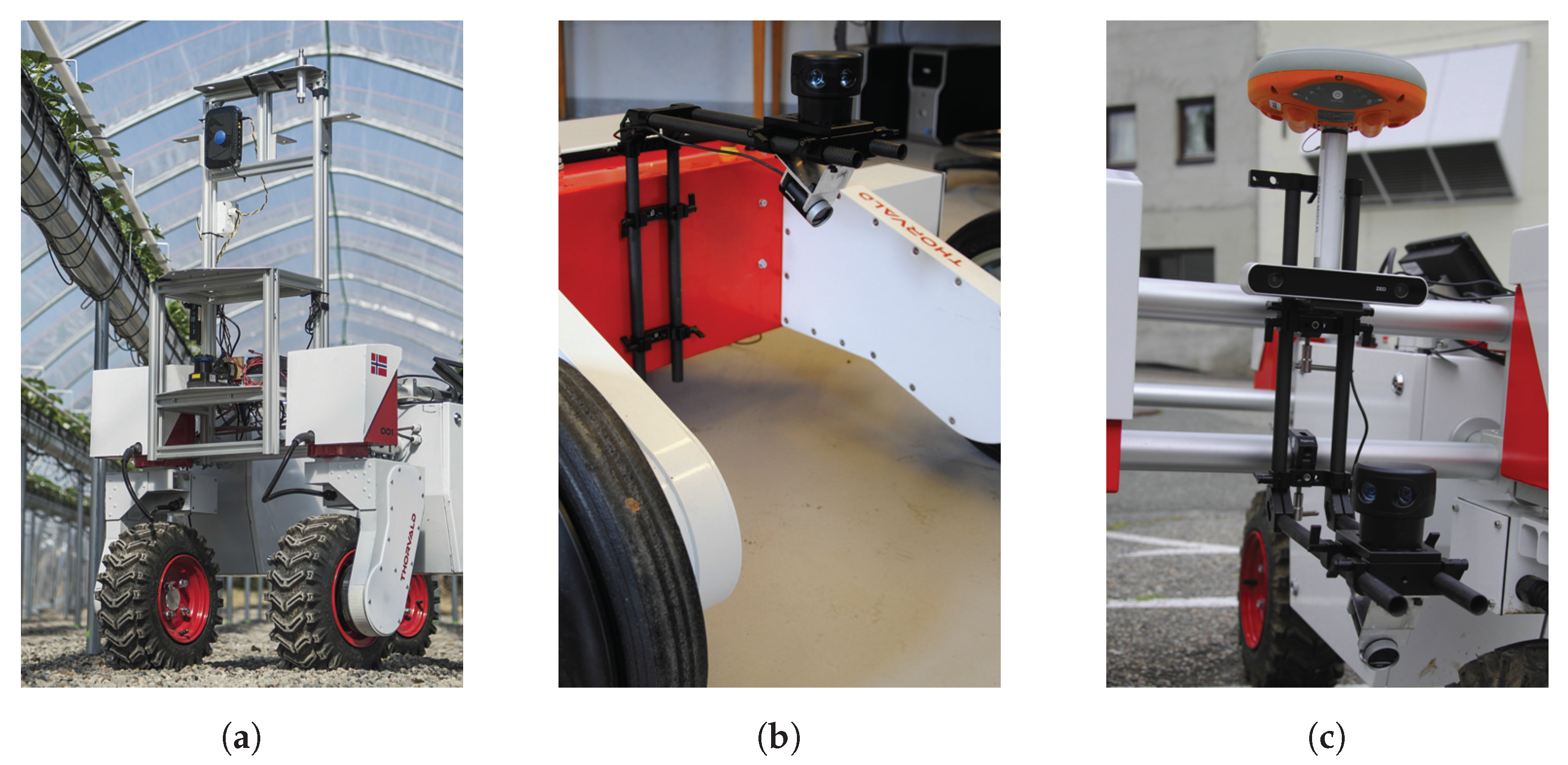
A few designs have been tested for mounting sensors. One design is based on aluminum profiles. The profiles can be assembled in various configurations and are slotted for easy sensor mounting. On the prototype shown in Figure 3a, the position of workhorse sensors, like the IMU and 2D LiDAR, in the module’s reference system has been accurately measured with a total station, which means that the positions of the sensors relative to each other are well known. An alternative module design is based on carbon rods and clamps. This makes for stiff, compact and lightweight mechanical support for sensors, which quickly can be reconfigured if necessary. Examples of this design are shown in Figure 3b,c.
2.2. Electric System
The Thorvald II robots are powered by 70 Ah or 35 Ah, 48 VDC lithium-ion battery packs. The battery management system (BMS) of each battery connects to the robot’s CAN, which means that parameters like SOC and battery status may be obtained.
Various robots may have different numbers of motor controllers and sensors, which all need power and a means of communication. It has been a key priority to simplify electric interfaces between modules. To this end, connectors and cables for connecting modules have been standardized, and a set of circuit boards has been designed, most important being the previously-mentioned main battery enclosure board.
The main battery enclosure board handles startup and shutdown of the computer, sensor and motor power circuits, making sure to charge capacitors on the motor bus through a current-limiting resistor before engaging the main contactor, issuing audible warning by means of a buzzer, e.g., if an emergency stop button is pressed, and so on. The board is controlled either from the main computer or through a pushbutton on the battery enclosure. The board also works as a hub for CAN communication and other signals to other modules. The board can serve three other modules and can be linked to a sister enclosure board, which then can serve three additional modules and which can be further linked to another sister enclosure board, which serves three additional modules, and so on. One single cable will supply a given module with CAN communication, 12 VDC control signal and low current power. The cable also includes send and return of the emergency stop circuit, which if broken will cut motor power. This is jumped on the enclosure board (main or sister) if an emergency stop button is not included on the given module. All enclosure boards and other module-specific boards include a connector for connecting an emergency stop button.
2.3. Software
It is important that the robot software does not limit the diversity in robots that can be built from the basic Thorvald II modules. When reconfiguring a robot, also the software must be able to adapt to the new configuration without the need for altering and recompiling the robot’s code. The software must be modular and able to adapt to new configurations.
To simplify the task of making the robot’s code modular, ROS (Robot Operating System) [11] has been chosen as the software framework. All processes that run on the robot are registered at the same ROS master, which makes them nodes in the same ROS network. Nodes are written to be independent of the hardware configuration whenever this is possible. Hardware parameters are loaded on the ROS parameter server from configuration-specific files at startup to tell the different nodes the current robot configuration’s specifications.
If, for example, a wide four-wheel drive (4WD), four-wheel steering (4WS) robot is reconfigured as a narrow differential drive robot, the programmer only needs to change width and length parameters and a parameter for the drive type, and the robot is ready to receive commands and publish odometry according to the new configuration.
2.4. Robot Configurations and Current Applications
Various robots may be constructed from the standard Thorvald II modules, e.g., robots with four-wheel drive and four-wheel steering, differential drive robots, Ackermann steering robots, robots with one-wheel drive and one-wheel steering, with or without suspension modules. The frame of the robot may be made stiff or flexible by adding or removing frame members. By combining simple custom frame components with standard modules, even greater variation can be achieved.
Several robots have been built from the Thorvald II modules, some of which can bee seen in the video in the Supplementary Materials. These robots are currently operating in vastly different environments, from open fields to polytunnels to greenhouses. Four of the many configurations that have been assembled and tested are described below together with current applications. These configurations have all been put through thorough testing in the agricultural environments that they were assembled to operate in and are now used in projects where the tool carried by the mobile base, not the mobile base itself, is studied. The mobile base is assumed to perform well, as experience shows that it does.
Section 2.4.1 and Section 2.4.2 describe robots made from only standard Thorvald II modules. Section 2.4.3 and Section 2.4.4 describe robots with some custom frame components.
2.4.1. Standard Configuration
The standard configuration of the Thorvald II robot has four-wheel drive and four-wheel steering, that is, it has four drive modules and four steering modules. It also has four suspension modules. The suspension modules allow drive modules to travel in the vertical direction, which means that the robot can adapt to uneven surfaces and maintain good traction on all drive wheels in rough terrain. The robot’s track width is 1.50 m, and the length of the robot is 1.35 measured from center to center between steering shafts.
The standard configuration has been used in various applications, such as robotic harrowing and robotic soil sampling, in several projects and experiments. The robot field capabilities have been verified through many hours of testing in various farm fields and in different weather conditions. The robot is depicted in Figure 4.
2.4.2. Narrow Configuration for Polytunnels
The standard configuration of the Thorvald II robot is intended for the open field and for driving in tractor tracks. The robot is therefore too wide for many environments. One such environment is polytunnels with crop on tabletops. For working in this environment, a slim robot was assembled. Like the standard robot, this robot still employs four drive modules and four steering modules, but it has a track width of only 0.56 m. As the ground surface in the polytunnels where the robot is operating is quite even, suspension modules are deemed unnecessary. Omitting these modules makes the robot shorter, with the length being 1.10 m between steering shafts, center to center.
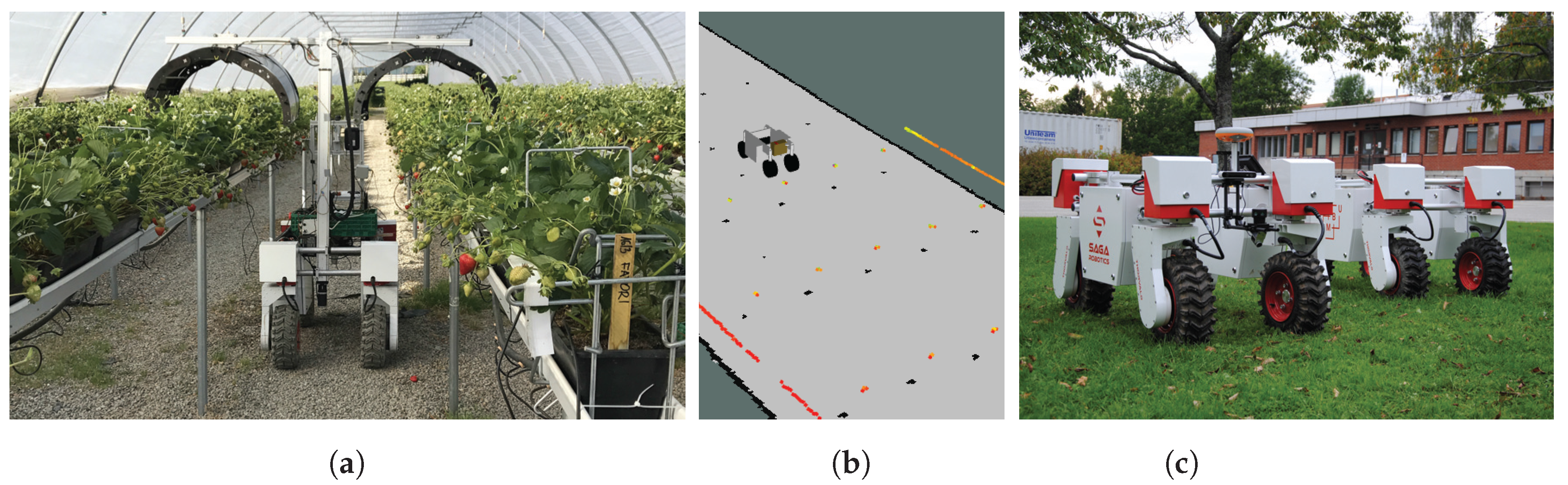
The robot is tasked with applying UV-B light to strawberries. The goal is to investigate the effect of UV-B light on mildew. The treatment is slow and must happen after sunset and has thus been robotized by the authors. The robot uses IMU, encoder odometry and LiDAR together with a map for localization and navigates to prerecorded way-points in the map. Lights are placed in arcs on either side of the robot, which automatically adjust to the correct height over the plants based on feedback from an array of ultrasonic sensors mounted on the arcs. This system was in autonomous operation 2 nights a week for four months during the 2017 season at a commercial strawberry farm in Norway. The system was, for the most part, overseen by farm employees (non-roboticists).
Similar robots are also being assembled for autonomous transportation of crates in polytunnels. Narrow robots made from the Thorvald II modules are depicted in Figure 5.
2.4.3. Tall Configuration for Wheat Phenotyping
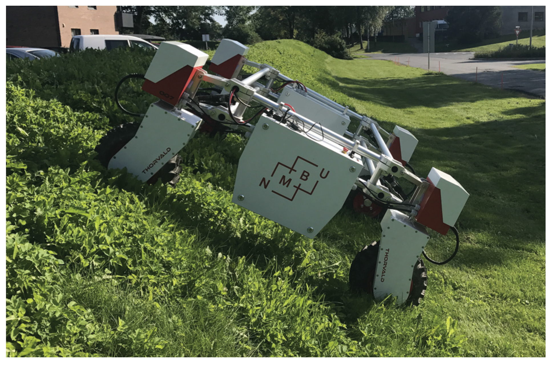
Research in plant phenomics is still highly dependent on manual labor to perform in-field measurements, and there is much to gain by automating the process [12]. Wheat phenotyping requires a robot that can drive over test plots of fully-grown wheat, recording data from above, without harming the plants. This therefore requires a tall robot [13]. For this purpose, a custom Thorvald configuration has been assembled [14]. To create this robot, a simple custom frame is welded together from steel pipes. This frame is then connected to standard Thorvald side frame components. To reduce costs and because this application is not an energy-demanding one, a differential robot design is chosen. The robot is fitted with two drive modules, two passive wheel modules and no steering modules. As spacing between plots is small, approximately 15 cm, the standard wheels on the drive modules are replaced by slimmer wheels. In addition, the robot is equipped with plant-separating covers. These covers gently separate plants to each side as the robot drives through the field. The robot is fitted with a RTK-GNSS receiver and an IMU, and navigates through predefined waypoints. It stops and captures images over each plot. The robot is fitted with two pairs of cameras. Each pair consists of one RGB camera and one monochromatic infrared camera. One pair is facing directly down; the other pair is mounted to the side at a 55 degree angle. The robot is depicted in Figure 6a,b. A four-wheel drive, four-wheel steering robot was also assembled with the same tall frame. This robot is depicted in Figure 6c.
2.4.4. Configuration for Greenhouses
Greenhouses will require different robots than the open field. One example of a greenhouse application is robotized UV-B light treatment of cucumber. Here, the robot needs to be able to drive on rails inside narrow rows. It must drive to the end of the row and back. Then, the robot must navigate to the next row on a concrete floor, all the while carrying a 2 m tall UV-B light rack. To this end, a simple custom enclosure was designed to hold components normally contained inside the standard Thorvald II battery enclosure. Two standard drive modules were connected to this custom enclosure and fitted with custom dual wheels, one for driving on rails, one for driving on concrete.
Navigation from row to row is done similarly to the polytunnel robot described in Section 2.4.2. A camera is used for aligning the robot with the rails. The robot is depicted in Figure 7.
2.5. Field Trials
As stated above, the standard Thorvald II configuration has four drive modules, four steering modules and four suspension modules. This makes the robot agile and powerful, but with eight motor-gear assemblies, it is naturally more costly to make than a differential drive robot with only two motor-gear assemblies. It is important to understand this trade-off between performance and cost when it comes to deciding on a specific robot configuration for a given task.
To quantify the differences between configurations in terms of performance, a series of tests was conducted. The configurations that are studied are all configurations intended for outdoor use with frames made from standard frame components. The tested configurations are listed in Table 1 and depicted in Figure 8. The “frame” column indicates if the robot’s frame is open or closed at the aft, i.e., whether the rear transversal frame members are removed or not to increase frame flexibility. Two robots are used in the experiments. One of the robots is configured as a standard Thorvald II robot. The other robot is rebuilt on-site for the other five tested configurations. For the differential drive configurations, rear corners are fitted with passive wheel modules with small, 25 cm in diameter caster wheels. The front steering modules are not replaced by rigid brackets, but electronically locked in the straight-ahead position by the steering module motors. The standard robot is fitted with one 35-Ah battery pack in the main battery enclosure; the other enclosure does not contain a battery. The other robot is fitted with one 70-Ah battery pack in the main battery enclosure and has no battery in the second enclosure. The tests are described in more detail below.
2.5.1. Traction Test
In this test, the studied robot is connected to a car (VW Golf IV) running in neutral through a load cell. Both the car and the robot are initially at rest on a tarmac surface. The robot then starts pulling the car in a straight line with constant motor command of 0.5 m/s. The car’s brakes are gradually applied to increase the robot’s pulling load until the robot loses traction and starts to spin. The largest stable value of the load cell is recorded. This test is done for Configurations 2, 4 and 6. Each robot is tested without additional load and with a payload of 137 kg. The payload consists of two weights on a wooden frame. The weight with the greater mass (67 kg) is placed so that the outer edge of the weight is aligned with the transversal front frame member; the other weight (50 kg) is aligned with the rear frame member. The wooden frame has a mass of 20 kg. Each robot is connected to the car by its vertical rear frame members. Due to the placement and angle of pull, the rear wheels are supporting the greater part of the robot’s weight when pulling. The test is recorded by two static cameras, the data from one of which are published to the same ROS network that is running on the robot. This data stream, together with other ROS topics are recorded for each test. The test setup is depicted in Figure 9.
2.5.2. Passing over Obstacles
In this test, each robot starts from a standstill and accelerates to a speed of 0.25 m/s, which is maintained for the duration of the test. The robot is teleoperated through a straight course populated by several obstacles, which the robots must overcome. The obstacles are numbered from start to finish, with dimensions as listed in Table 2. The obstacles are placed as shown in Figure 10.
Each robot drives until it overcomes all obstacles or until it gets stuck or fails to overcome an obstacle. All runs are recorded by a static camera and a camera on the robot facing the robot’s front right corner.
2.5.3. Incline Test
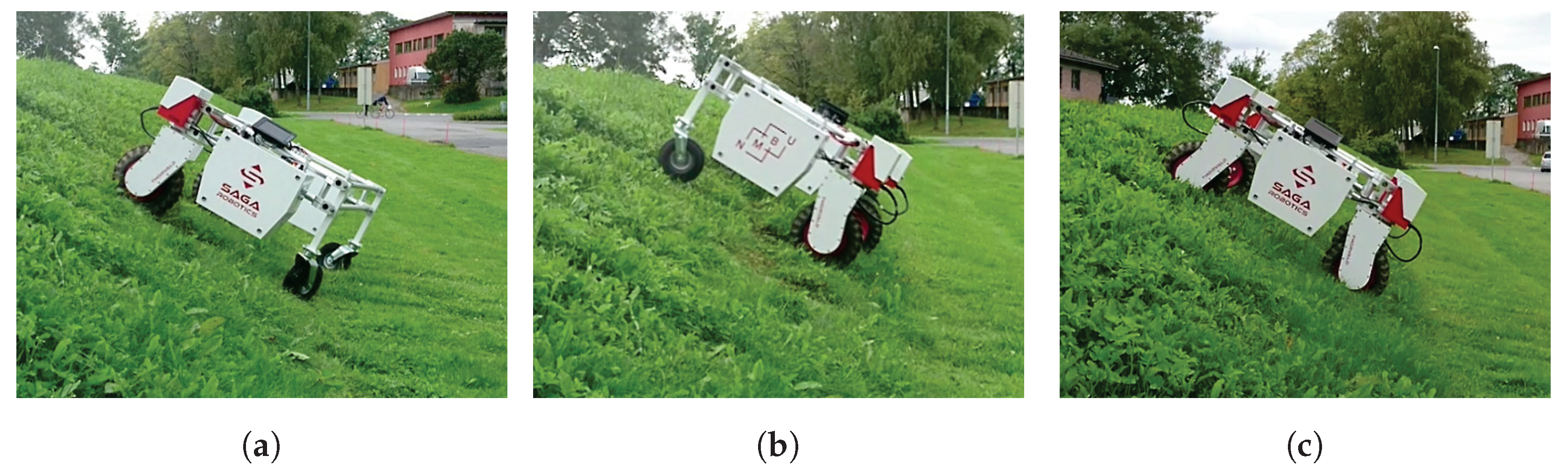
In this test, each robot starts from a standstill on level ground and accelerates to a speed of 1.0 m/s. The robot then enters a 30 degree steep, grass-covered incline and maintains constant motor command until it reaches the top. After reaching the top, the robot starts reversing, descends to the middle of the incline, comes to a stop, starts from a standstill and climbs to the top one more time. The test finishes when the robot reaches the top for the second time, or fails to climb the incline. The robots are teleoperated for the duration of the test, and all runs are recorded by a static camera. The incline is depicted in Figure 11.
3. Results
3.1. Traction Test
All robots managed to pull the car when in neutral. The car’s brakes were gradually applied until each robot lost traction. The resulting maximum pulling forces with and without payload are listed in Table 3. Due to the robot being connected to the car from its rear frame and the angle of pull, the front of Configuration 2 lifted when not carrying the extra payload, and the test was therefore aborted before the robot lost traction. With payload, the load cell failed after reaching 2500 N. At this point, the rear wheels had a calculated power consumption of three-times the rated power. It was therefore decided not to repeat the test with a new load cell. The results are listed in Table 3. Video from the test can be found in the Supplementary Materials.
For this test, one robot was reconfigured for all three tested configurations. The order in which the robots were tested was Configuration 4, then 6, then 2. The first rebuild, from differential drive to 1WD/1WS, was performed in 15 min. The second rebuild, from 1WD/1WS to 4WD/4WS, was performed in less than 30 min.
3.2. Passing over Obstacles
All four-wheel drive configurations, Configurations 1, 2 and 3, passed all obstacles. Configuration 4 failed at Obstacle 4, while Configuration 5 failed at the very first obstacle. Obstacles 1 and 2 were rotated 90 degrees (in the horizontal plane) for Configurations 4 and 5 to avoid obstacles getting stuck between the robot’s front and rear wheels. The only configuration that managed to keep all wheels in connection with the ground throughout the test was Configuration 3, the robot with four-wheel drive and open frame. Configuration 1 lost connection with the ground on one wheel when driving over two obstacles simultaneously on diagonally-opposite corners. It also lifted slightly on one wheel when passing Obstacle 5. Configuration 2 lost connection with the ground on one or two wheels on all the obstacles. Figure 12 shows the robots during testing.
3.3. Incline Test
All four-wheel drive configurations, that is Configurations 1, 2 and 3, succeeded in climbing the incline from a flying start, as well as from standstill mid-incline. These configurations had no problems while descending and stopping in the middle of the incline. With the drive wheels in the front, Configurations 4 and 5 failed at reaching the top as they both lost traction in the middle of the incline. When driving with drive modules at the rear, however, both Configurations 4 and 5 were able to reach the top, from a flying start, descending and starting from rest mid-incline, despite losing traction sporadically. Figure 13 shows some of the robots during testing.
4. Discussion
As stated above, the presented modules have been used to assemble vastly different robots operating in various environments. In the authors’ experience, the modular system greatly reduces cost and development time related to the creation of new robots. This is especially good for researchers who tend to operate in different environments in different projects, as robots can quickly be adapted for existing farm infrastructure, then later rebuilt to be used in other farms. A robot previously configured for the open field is easily reconfigured for use in polytunnels; in fact, several of the existing Thorvald II robots have gone back and forth through this very transformation several times. It is also worth emphasizing the fact that only two robots were involved in the creation of the six different designs used in the field trials presented in this paper, with robots being reconfigured on-site with basic hand tools, such as Alan keys and screwdrivers.
With a modular system, bad design choices may be undone by changing modules or by altering the frame geometry. Adding steering motors to a previously differential drive robot or changing passive wheels for active ones can be done in a matter of minutes, and for robots using standard frame components, the robot’s width can be modified using one single Alan key. This reduces the risk when designing new robots and allows robots to be adapted in-field.
Various robots made from Thorvald II modules are in operation in the real-world environments they were assembled to operate in and are successfully working in open fields, in polytunnels and in greenhouses on real farms.
Field Trials
Unsurprisingly, four-wheel drive performed better than two-wheel drive in all the presented field trials. Other than having two less propulsion motors, there seems to be two important reasons why the differential robots fail. One, the diameter of the rear caster wheels is too small for the obstacles. As almost all obstacles were taller than half the diameter of the caster wheel, the robot struggled to pull the passive wheels over the obstacles and ended up either losing traction on the drive wheels or pulling the obstacles along the ground. This was especially apparent when comparing the closed and open frame configurations. When the front drive wheel of the closed frame configuration climbed an obstacle, the rear wheel was lifted from the ground because of the stiffer closed frame. This helped the caster clear the obstacle. With the open frame, the caster remained in connection with the ground until it hit the obstacle, effectively stopping the robot.
The second reason why the differential robots underperformed in these tests is that the robot is too light-weight to maintain good traction, especially on the side with no battery. When driving the robot around the test area, the robot performed much better when carrying the 137-kg load compared to driving with no extra load. Similarly, the differential drive robots were able to get up the incline when the drive modules were at the aft, supporting more of the robot’s weight, but not when the drive modules were at the front. This suggests that these configurations may need some added weight when operating in difficult terrain.
Although Configuration 2 completed all trials without too many difficulties, it did so notably less gracefully than the other two four-wheel drive configurations. The stiffer closed frame combined with the lack of suspension resulted in wheels lifting far off the ground when driving over obstacles. On the other hand, none of the field trials presented here seemed to notably challenge Configuration 1 or 3. Configuration 3 was, with its open frame, the only robot to keep all wheels in connection with the ground at all times, even with one wheel on the tallest obstacle. An open frame saves the cost of suspension modules, but the relative movement of the robot’s side may complicate the task of adapting tools to the robot compared to a stiff frame and suspension.
5. Conclusions
In this paper we have shown how modular robots may be a time saver when it comes to adapting to new environments. The fact that a robot can be modified in-field means that the robot quickly can be altered to adapt to new or changing environment variables. We have shown how robots based on the Thorvald II system are able to operate in several vastly different environments and given examples of current applications. From the field tests, we learned how flexible frames may be a solution for creating light-weight, low-cost field robots. This is something that will be investigated further in our future work.
The work on further developing hardware and software for the Thorvald II system is an ongoing process, and new configurations of the robot will continue to be created as they are needed.
Supplementary Materials
The following are available online at https://www.dropbox.com/sh/8a8mbdx33crlz0h/AAAw4Cs15s7NQkLeoXQlUizca?dl=0: videos from field trials.
Acknowledgments
The authors would like to thank Øystein Sund and Marius Austad for their continued contributions in developing the Thorvald II platform. The authors would also like to thank Eirik Wormdahl and Halvard Grimstad for their contribution during the field trials presented in this paper and Kristine Skattum and Rémy Zakaria for the contribution they have made through their Master’s theses to the phenotyping and greenhouse robot configurations.
Author Contributions
Lars Grimstad and Pål Johan From conceived, designed and performed the experiments, analyzed the data and wrote the paper.
Conflicts of Interest
The authors declare no conflict of interest.
Abbreviations
The following abbreviations are used in this manuscript:
| CAN | Controller Area Network |
| LED | Light Emitting Diode |
| DC | Direct Current |
| BMS | Battery Management System |
| SOC | State of Charge |
| 4WD | Four-Wheel Drive |
| 4WS | Four-Wheel Steering |
| RTK | Real-Time Kinematic |
| GNSS | Global Navigation Satellite System |
References
- Lowder, S.K.; Skoet, J.; Raney, T. The Number, Size, and Distribution of Farms, Smallholder Farms, and Family Farms Worldwide. World Dev. 2016, 87, 16–29. [Google Scholar] [CrossRef]
- Batey, T. Soil compaction and soil management—A review. Soil Use Manag. 2009, 25, 335–345. [Google Scholar] [CrossRef]
- Nawaz, M.; Bourrié, G.; Trolard, F. Soil compaction impact and modelling. A review. Agron. Sustain. Dev. 2013, 33, 291–309. [Google Scholar] [CrossRef]
- Ruckelshausen, A.; Biber, P.; Dorna, M.; Gremmes, H.; Klose, R.; Linz, A.; Rahe, F.; Resch, R.; Thiel, M.; Trautz, D.; et al. BoniRob—An autonomous field robot platform for individual plant phenotyping. In Proceedings of the European Conference on Precision Agriculture, Wageningen, The Netherlands, 6–8 July 2009; pp. 841–847. [Google Scholar]
- Bangert, W.; Kielhorn, A.; Rahe, F.; Albert, A.; Biber, P.; Grzonka, S.; Haug, S.; Michaels, A.; Mentrup, D.; Hänsel, M.; et al. Field-Robot-Based Agriculture: ”RemoteFarming. 1” and “BoniRob-Apps”. In Proceedings of the 71th Conference Land. Technik—AgEng 2013, Hannover, Germany, 8–9 November 2013; pp. 439–445. [Google Scholar]
- Underwood, J.P.; Calleija, M.; Taylor, Z.; Hung, C.; Nieto, J.; Fitch, R.; Sukkarieh, S. Real-time target detection and steerable spray for vegetable crops. In Proceedings of the International Conference on Robotics and Automation: Robotics in Agriculture Workshop, Seattle, WA, USA, 25–30 May 2015. [Google Scholar]
- Bawden, O.; Ball, D.; Kulk, J.; Perez, T.; Russell, R. A lightweight, modular robotic vehicle for the sustainable intensification of agriculture. In Proceedings of the Australian Conference on Robotics and Automation (ACRA 2014), Melbourne, Australia, 2–4 December 2014; Australian Robotics & Automation Association ARAA: Broadway, Australia, 2014. [Google Scholar]
- Jensen, K.; Larsen, M.; Nielsen, S.H.; Larsen, L.B.; Olsen, K.S.; Jørgensen, R.N. Towards an Open Software Platform for Field Robots in Precision Agriculture. Robotics 2014, 3, 207–234. [Google Scholar] [CrossRef] [Green Version]
- Arbo, M.H.; Utstumo, T.; Brekke, E.; Gravdahl, J.T. Unscented Multi-Point Smoother for Fusion of Delayed Displacement Measurements: Application to Agricultural Robots. Model. Identif. Control 2017, 38, 1–9. [Google Scholar] [CrossRef]
- Grimstad, L.; Pham, C.D.; Phan, H.T.; From, P.J. On the design of a low-cost, light-weight, and highly versatile agricultural robot. In Proceedings of the 2015 IEEE Workshop on Advanced Robotics and Its Social Impacts (ARSO 2015), Lyon, France, 30 June–2 July 2015. [Google Scholar]
- Quigley, M.; Gerkey, B.; Conley, K.; Faust, J.; Foote, T.; Leibs, J.; Berger, E.; Wheeler, R.; Ng, A. ROS: An open-source Robot Operating System. In Proceedings of the IEEE International Conference on Robotics and Automation (ICRA) Workshop on Open Source Robotics, Kobe, Japan, 12–17 May 2009. [Google Scholar]
- Underwood, J.; Wendel, A.; Schofield, B.; McMurray, L.; Kimber, R. Efficient in-field plant phenomics for row-crops with an autonomous ground vehicle. J. Field Robot. 2017, 34, 1061–1083. [Google Scholar] [CrossRef]
- Burud, I.; Lange, G.; Lillemo, M.; Bleken, E.; Grimstad, L.; From, P.J. Exploring Robots and UAVs as Phenotyping Tools in Plant Breeding. In Proceedings of the IFAC 2017 World Congress, Toulouse, France, 9–14 July 2017. [Google Scholar]
- Grimstad, L.; Skattum, K.; Solberg, E.; Loureiro, G.D.S.M.; From, P.J. Thorvald II Configuration for Wheat Phenotyping. In Proceedings of the IROS Workshop on Agri-Food Robotics: Learning from Industry 4.0 and Moving into the Future, Vancouver, BC, Canada, 24–27 September 2017. [Google Scholar]
Figure 1.
A few examples of robots assembled from Thorvald II modules.

Figure 2.
Examples of Thorvald II modules. A: battery enclosure; B: drive module; C: steering module; D: suspension module; E: early prototype of the sensor-interfacing module.
Figure 2.
Examples of Thorvald II modules. A: battery enclosure; B: drive module; C: steering module; D: suspension module; E: early prototype of the sensor-interfacing module.

Figure 3.
(a) The initial prototype of the Thorvald II robot with an early sensor mounting rack prototype; (b,c) racks based on carbon tubes and clamps.
Figure 3.
(a) The initial prototype of the Thorvald II robot with an early sensor mounting rack prototype; (b,c) racks based on carbon tubes and clamps.

Figure 4.
The Thorvald II standard configuration.

Figure 5.
Narrow robots for polytunnels assembled from Thorvald II modules. (a) A robot for treating strawberries with UV light in polytunnels; (b) this robot is localized in a map of the tunnel; (c) two robots to be used for transporting crates of strawberries in polytunnels.
Figure 5.
Narrow robots for polytunnels assembled from Thorvald II modules. (a) A robot for treating strawberries with UV light in polytunnels; (b) this robot is localized in a map of the tunnel; (c) two robots to be used for transporting crates of strawberries in polytunnels.

Figure 6.
Tall robots for wheat phenotyping assembled using Thorvald II modules together with a simple, custom frame. (a,b) A differential drive robot with covers for separating plants; (c) a four-wheel drive, four-wheel steering robot.
Figure 6.
Tall robots for wheat phenotyping assembled using Thorvald II modules together with a simple, custom frame. (a,b) A differential drive robot with covers for separating plants; (c) a four-wheel drive, four-wheel steering robot.
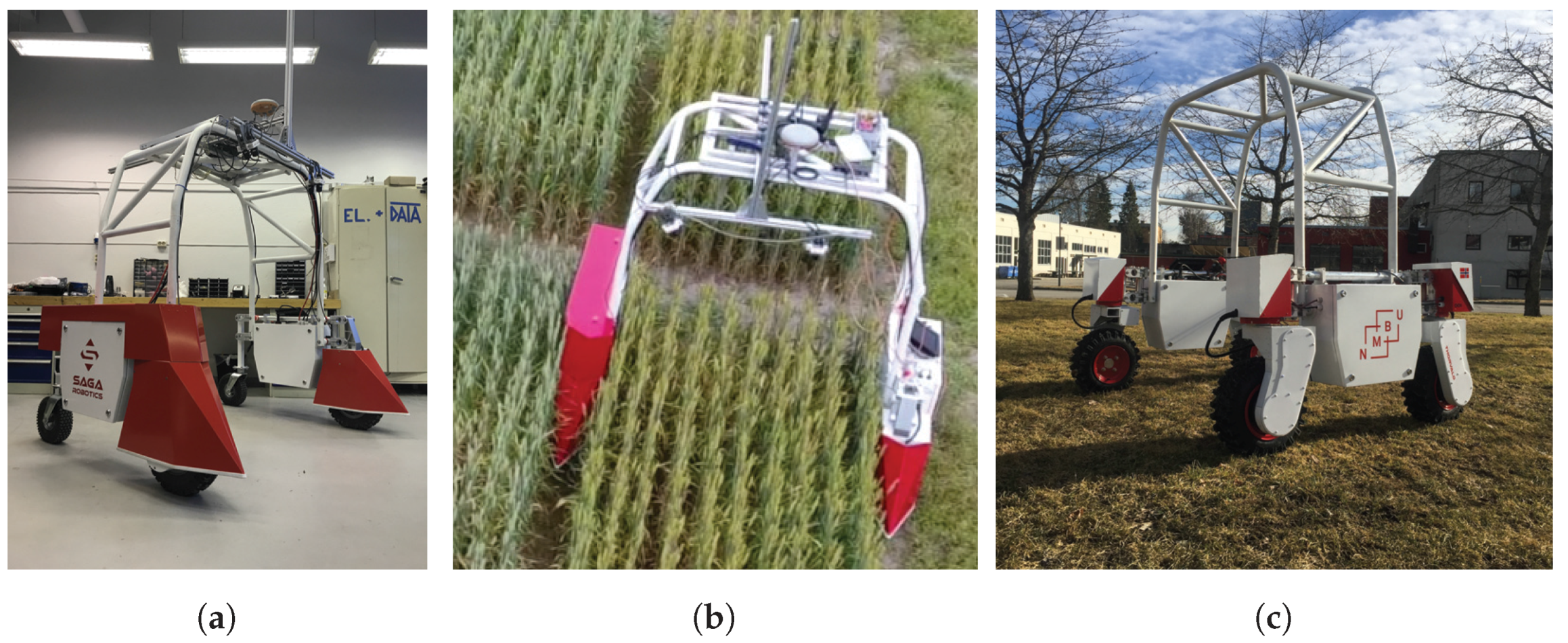
Figure 7.
A robot for UV treatment of cucumber in greenhouses assembled from Thorvald II modules and a simple custom frame. (a) The robot on the concrete floor; (b) the transition from concrete floor to rails as seen by the robot; here, the robot is identifying the rails using a single RGB camera; (c) the robot on rails.
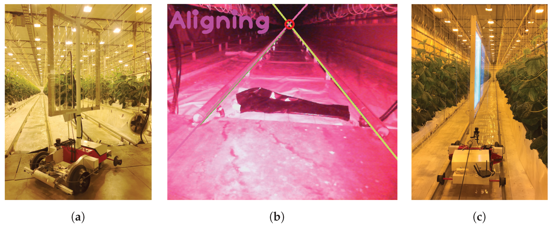
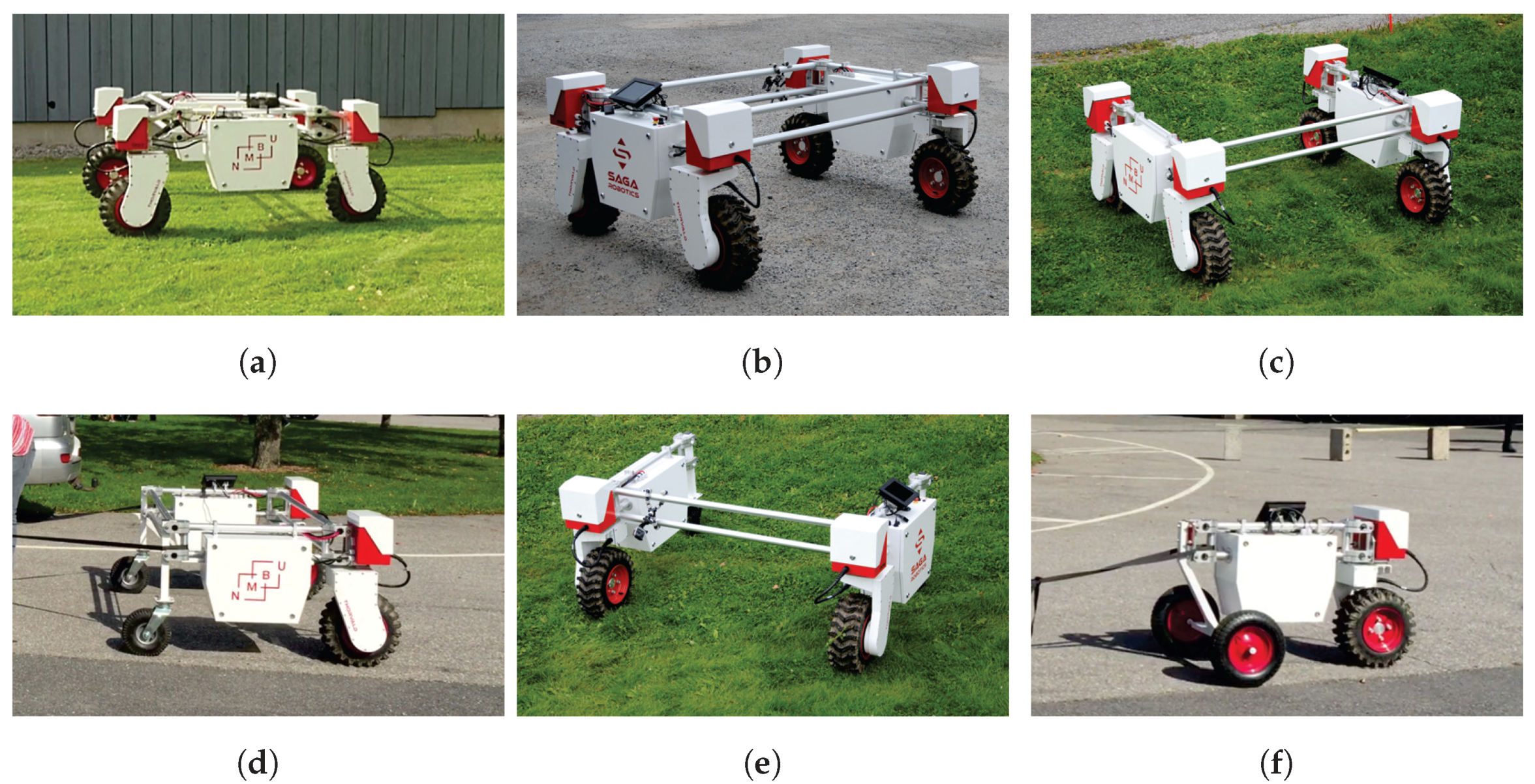
Figure 8.
Robot configurations used in field trials. (a) Configuration 1: 4WD, 4WS, four suspension modules, closed frame; (b) Configuration 2: 4WD, 4WS, no suspension modules, closed frame; (c) configuration 3: 4WD, 4WS, no suspension modules, open frame; (d) Configuration 4: 2WD, 0WS, no suspension modules, closed frame; (e) Configuration 5: 2WD, 0WS, no suspension modules, open frame; (f) Configuration 6: 1WD, 1WS, no suspension modules.

Figure 9.
The setup for the traction test. Here, the robot is carrying a 137-kg payload.
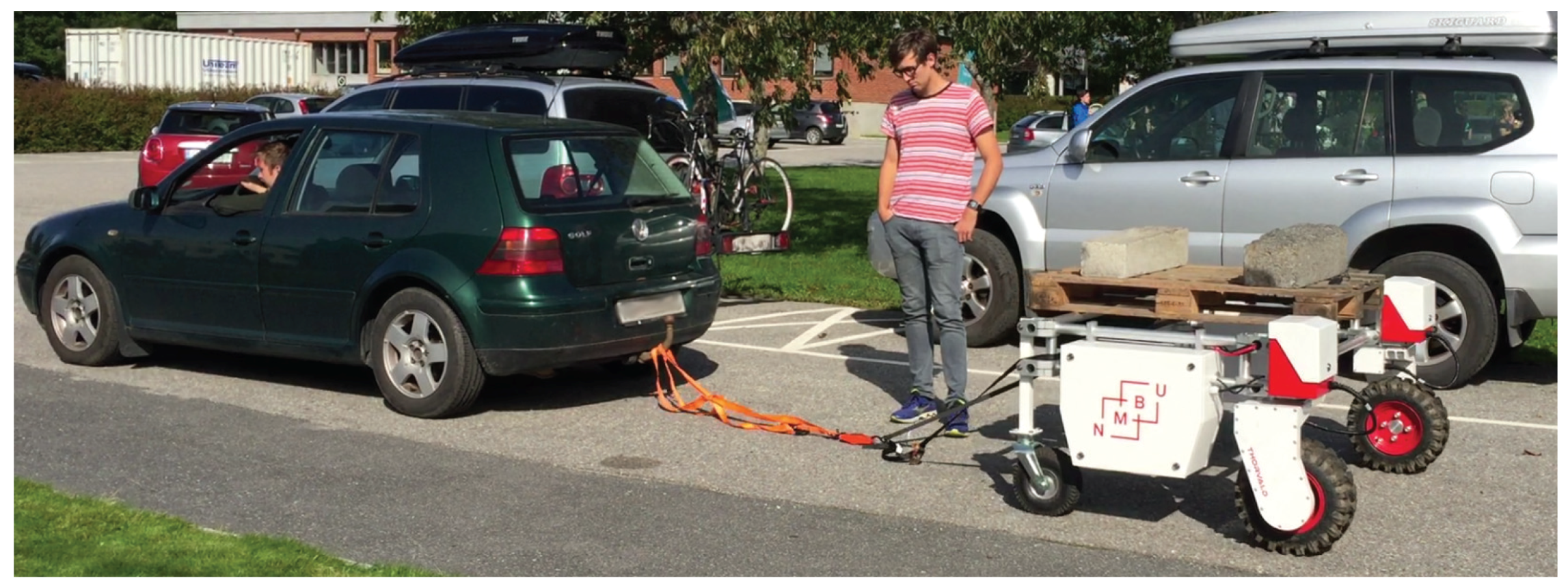
Figure 10.
Obstacles for the robots to pass over. Obstacle 1 is at the far left.
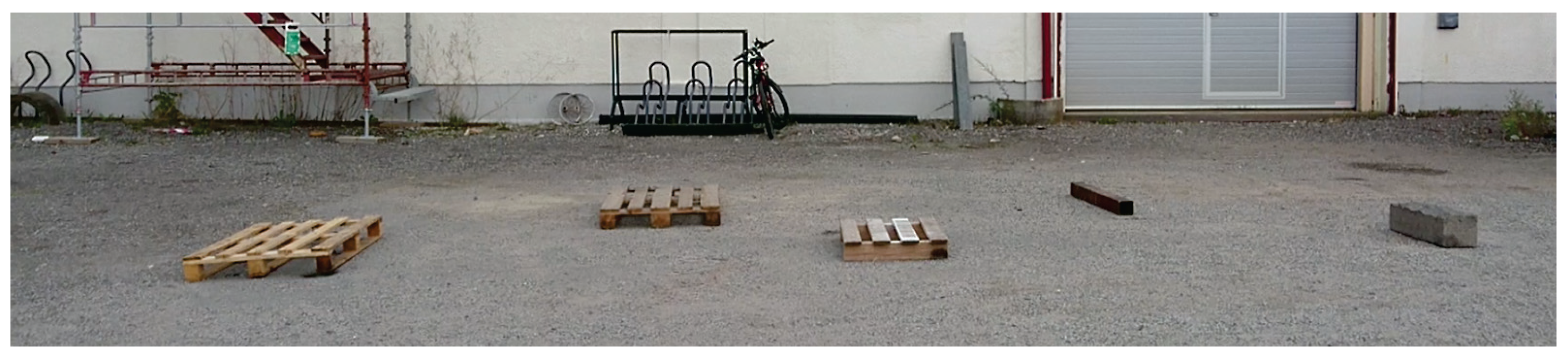
Figure 11.
Thirty degree grass-covered incline to be climbed by the tested robots.
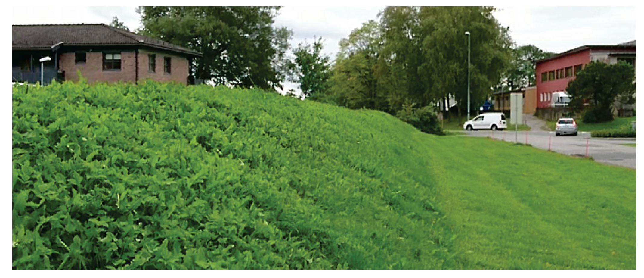
Figure 12.
Thorvald robots during the obstacle test. (a) Configuration 1: 4WD, 4WS, four suspension modules, closed frame; (b) Configuration 2: 4WD, 4WS, no suspension modules, closed frame; (c) Configuration 3: 4WD, 4WS, no suspension modules, open frame; (d) Configuration 4: 2WD, 0WS, no suspension modules, closed frame; (e) Configuration 5: 2WD, 0WS, no suspension modules, open frame.
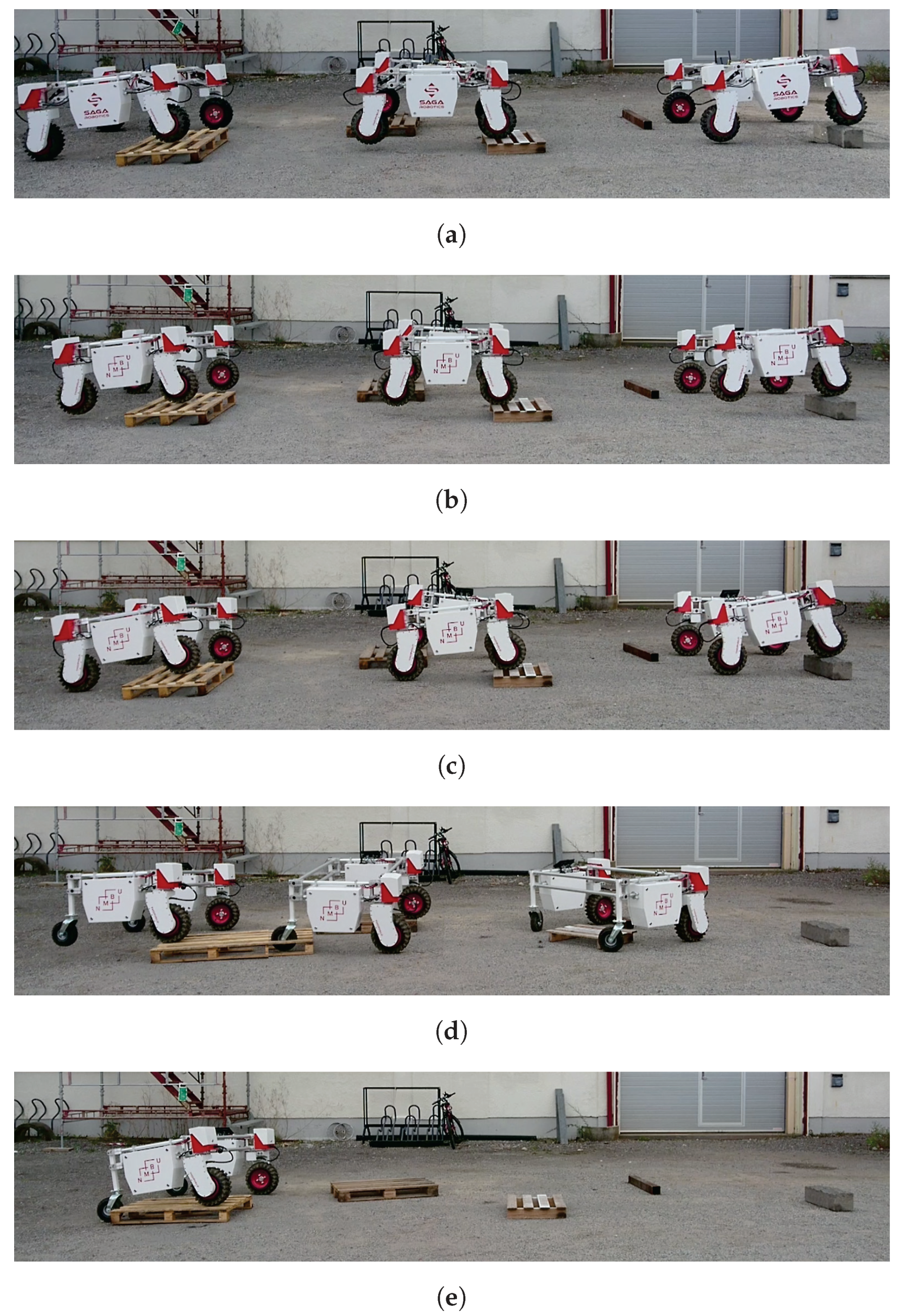
Figure 13.
(a) Differential drive configuration failing to climb the incline when drive modules are at the front; (b) differential drive configuration succeeding at climbing the incline when drive wheels are at the rear; (c) all four-wheel drive configurations succeeded at climbing the incline without difficulties.

Table 1.
Robot configurations used in field trials.
| Configuration | Width (m) | Length (m) | Drive Mods | Active Steering Mods | Suspension Mods | Frame |
|---|---|---|---|---|---|---|
| 1 | 1.50 | 1.35 | 4 | 4 | 4 | closed |
| 2 | 1.50 | 1.10 | 4 | 4 | 0 | closed |
| 3 | 1.50 | 1.10 | 4 | 4 | 0 | open |
| 4 | 1.50 | 1.10 | 2 | 0 | 0 | closed |
| 5 | 1.50 | 1.10 | 2 | 0 | 0 | open |
| 6 | N/A | 1.10 | 1 | 1 | 0 | N/A |
Table 2.
Sizes of obstacles in the obstacle course.
| Obstacle | Height (cm) | Width (cm) | Length [cm] |
|---|---|---|---|
| 1 | 14 | 79 | 120 |
| 2 | 13 | 79 | 117 |
| 3 | 12 | 60 | 80 |
| 4 | 10 | 101 | 10 |
| 5 | 18 | 70 | 20 |
Table 3.
Pulling force for different robot configurations with and without a 137-kg payload.
| Config. | Pulling Force without Payload (N) | Pulling Force with Payload (N) |
|---|---|---|
| 2 | 1900 * | 2500 ** |
| 4 | 700–750 | 1100–1200 |
| 6 | 300 | not tested |
* Lifted on front wheels due to angle and location of pull; ** load cell failed.
© 2017 by the authors. Licensee MDPI, Basel, Switzerland. This article is an open access article distributed under the terms and conditions of the Creative Commons Attribution (CC BY) license (http://creativecommons.org/licenses/by/4.0/).
Share and Cite
MDPI and ACS Style
Grimstad, L.; From, P.J. The Thorvald II Agricultural Robotic System. Robotics 2017, 6, 24. https://doi.org/10.3390/robotics6040024
AMA Style
Grimstad L, From PJ. The Thorvald II Agricultural Robotic System. Robotics. 2017; 6(4):24. https://doi.org/10.3390/robotics6040024
Chicago/Turabian StyleGrimstad, Lars, and Pål Johan From. 2017. "The Thorvald II Agricultural Robotic System" Robotics 6, no. 4: 24. https://doi.org/10.3390/robotics6040024
Note that from the first issue of 2016, this journal uses article numbers instead of page numbers. See further details here.