The Development of Highly Flexible Stretch Sensors for a Robotic Hand


1
Department of Mechanical Engineering, University of Auckland, Auckland 1010, New Zealand
2
Department of Materials Engineering, Ecole Nationale Supérieure d’Ingénieurs de Caen, 14000 Caen, France
*
Author to whom correspondence should be addressed.
Robotics 2018, 7(3), 54; https://doi.org/10.3390/robotics7030054
Submission received: 3 August 2018
/
Revised: 7 September 2018
/
Accepted: 8 September 2018
/
Published: 11 September 2018
(This article belongs to the Special Issue Feature Papers)
Abstract
:Demand for highly compliant mechanical sensors for use in the fields of robotics and wearable electronics has been constantly rising in recent times. Carbon based materials, and especially, carbon nanotubes, have been widely studied as a candidate piezoresistive sensing medium in these devices due to their favorable structural morphology. In this paper three different carbon based materials, namely carbon black, graphene nano-platelets, and multi-walled carbon nanotubes, were utilized as large stretch sensors capable of measuring stretches over 250%. These stretch sensors can be used in robotic hands/arms to determine the angular position of joints. Analysis was also carried out to understand the effect of the morphologies of the carbon particles on the electromechanical response of the sensors. Sensors with gauge factors ranging from one to 1.75 for strain up to 200% were obtained. Among these sensors, the stretch sensors with carbon black/silicone composite were found to have the highest gauge factor while demonstrating acceptable hysteresis in most robotic hand applications. The highly flexible stretch sensors demonstrated in this work show high levels of compliance and conformance making them ideal candidates as sensors for soft robotics.
1. Introduction
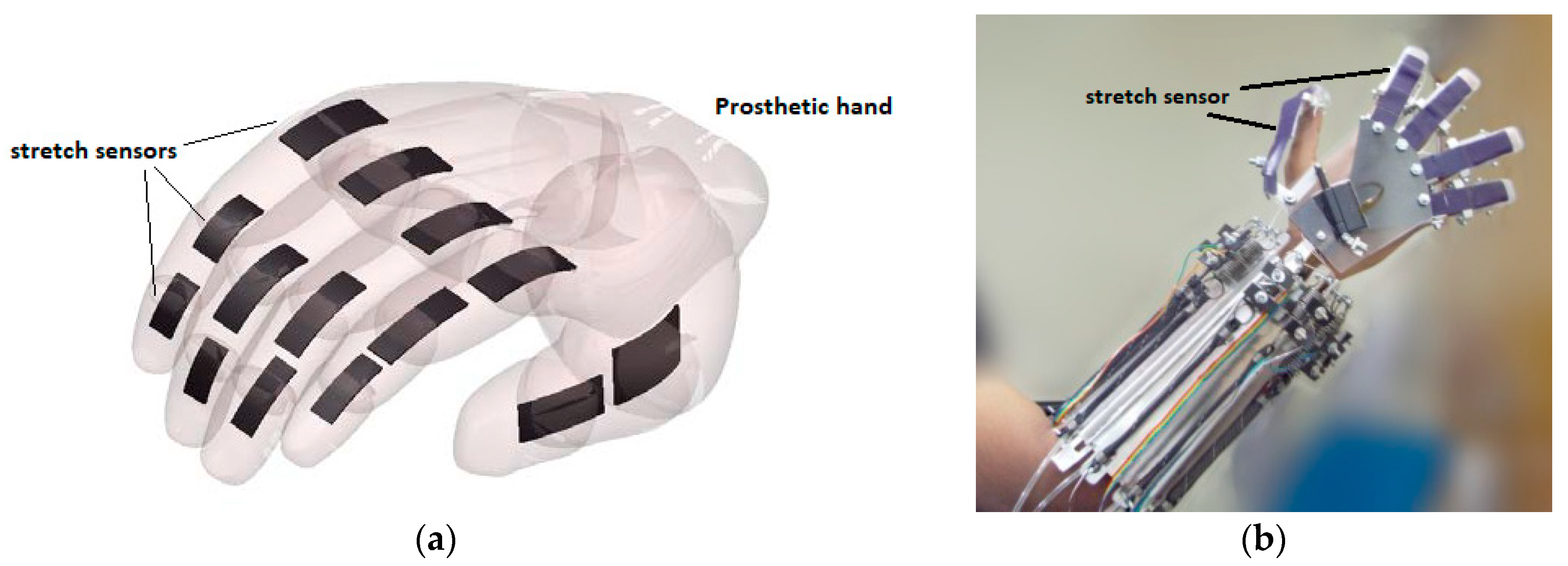
The ever-growing field of robotics especially as used to complement human motions has given rise to the need for light weight and flexible sensors. Such devices must be highly compliant with excellent performance to achieve the desired end task and at the same time be comfortable for the end user. There is a demand for sensors, actuators, and electronics that are light weight, low profile, and intrinsically flexible. For instance, stretch sensors can be mounted on a wearable device such as a prosthetic hand, data glove, or exoskeleton to provide vital information on the angular orientation of the joints, as illustrated in Figure 1. The use of traditional metallic and semiconducting techniques in this sensing field, though previously demonstrated [1,2,3], has limited potential due to the amount of stretch/strain that the device can undergo before fatigue, which in some areas might be well beyond the traditional strain sensor’s capabilities. The term stretch and strain will be interchangeably used here.
A nanocomposite printing technique was developed [4] to produce flexible carbon-silicone composite patterns that can be embedded in a flexible and highly stretchable medium. As the carbon-silicone composites are intrinsically flexible and stretchable while being conductive even at stretch levels of up to 300% [4], their resistance changes can be used to indicate the stretch levels, which can be used to deduce the amount of mechanical movement. To overcome the challenges involved in development of capacitance based sensor architecture for measuring strains [5,6,7], the piezoresistive approach demonstrated in this work uses homogenously dispersed carbon based conductive materials in a silicone rubber medium. This elastic medium imparts high levels of flexibility and stretchability, while the dispersed carbon based conductive media, i.e., Multi-walled Carbon Nanotubes (MWCNTs), Graphene nano-platelets (GNP), and Carbon black (CB), explored within the scope of this article, imparts electrical conductivity. This architecture helps reducing the cracking and fluid flow induced fatigue over large strains in traditional piezoresistive based stretch sensor architecture [8,9,10,11].
While the majority of recent research focusing on large stretch sensor development has used carbon nanotubes (CNT) based composites [8,11,12,13,14,15,16] as detailed in Table 1, the main drawback of using CNT based sensors is the carcinogenic nature of this particular carbon allotrope [17,18,19]. While the stretch sensor architecture developed by Yamada et al. [12] has an appreciable working strain range, the gauge factor (GF) of the sensor is very small. The fibrous structure of CNTs can help ensure conductivity of the composite at very large strains owing to potential contact between criss-crossing nano-tubes. However exposure to low concentrations of CNTs during device fabrication and exposed carbon nanotubes in some sensor architectures [14,20] might possibly be harmful. The sensor architecture of Ryu et al. [14], though it achieves high working stretches and GF, results in exposed MWCNT fibers, which may potentially increase the carcinogenic hazard, should the elastic medium rupture in use. Furthermore, several of these sensors have a non-linear response, with substantial variation of GF over the working range.
Though efforts have been made to overcome the drawbacks of early sensor architectures by developing carbon based nanocomposites combined or encapsulated within polymer matrices [4,13,14,15,16,21,22,23], when carbon based conductive nanoparticles are mixed within a curable elastomer matrix to form a cured and highly-elastic conductive trace, it is hoped that the risk involved in using these materials as sensing elements will be greatly reduced. Giffney et al. [4] presented MWCNT/Ecoflex composite based sensor in which the conductive phase has been recently identified to be carcinogenic. We aim to addresses this issue by exploring suitable alternatives to the carcinogenic CNTs. Using a 3D printer platform to control the deposition of the carbon-elastomer composite on the elastomer substrate, the patterns that can be printed is simply limited only be the printer’s extruder movement, which allows limitless patterns both in two and three dimensions. The deposited carbon/elastomer composite is then completely embedded within elastomer layers, further improving the mechanical strength of the sensor to be capable of measuring large stretch. In the present work, the main aim of our contribution was to develop large stretch sensors with strains of up to 250% using three different carbon-elastomer composites, and focus on studying the variation in electromechanical response to understand the effect of the carbon morphology on the sensors response was also analyzed. Preliminary testing results of carbon/elastomer composite based sensor integrated power assistive robotic exoskeleton is also presented.
2. Materials and Methods
This work presents large stretch sensors consisting of conductive, serpentine shaped 2D carbon-elastomer composite patterns that are 205 mm long and fully embedded within a rectangular silicon based elastomer matrix. The surrounding elastomer matrix improves the mechanical strength of the sensor and at the same time insulates the conductive composite trace from the surrounding environment increasing the compliance of the sensor. The three different carbon based composite sensors (MWCNT, CB, and GNP) are stretched to 200–250% and their response is measured simultaneously. Further experiments to understand the conduction mechanisms in different forms of carbon composites with respect to change in temperature was also carried out.
2.1. Preparation and Printing of Carbon Elastomer Composites
Fabrication of the stretch sensors began with preparation of the carbon composites in the elastomer medium. The elastomer used across all three carbon-elastomer composites is the commercially available Ecoflex 00-30 [24], which can be stretched up to 900% [25]. This platinum catalyzed, highly elastic silicone based elastomer is formulated as two part mixing curable kit and has a working time of 40 min. The three types of carbon particles used in the fabrication of the discussed stretch sensors were obtained from commercial suppliers. Multi-wall carbon nanotubes (MWCNTs) with diameters ranging from 10–30 nm and with lengths over 2 µm were purchased from Shenzhen Nanotech Port Co. Ltd. Conductive carbon black (CB) with a particle size of 50 nm was purchased from Fuelcell Store (Vulcan® XC72R). Graphene nano platelets (GNP) of 5 nm in thickness and 5 μm in size was obtained from Pascual Ferrer Renau –Emfutur for preparing the composites
MWCNT, GNP, and CB were added to a 1:1 mixture of the elastomer parts in varying mass fractions depending on the desired sensor response. While higher ratios of carbon to elastomer would improve conductivity, the increased concentration of carbon impairs the printability of the composite. The composite of carbon particles in uncured silicone is thoroughly mixed to ensure homogeneity of the dispersion using a Kurabo planetary centrifuge mixer (Mazerustar KK-50S). This mixing degasses the composite while mixing for uniform extrusion rates during printing process, removing bubbles without requiring vacuum filling of the syringe. The filled syringe and the plunger are then loaded into the printer platform, which is moved by a precision three axis linear stage. Deposition is carried out with a printer head motion speed of 2.5–3 mm/s as speeds above this created discontinuity in the extruded traces.
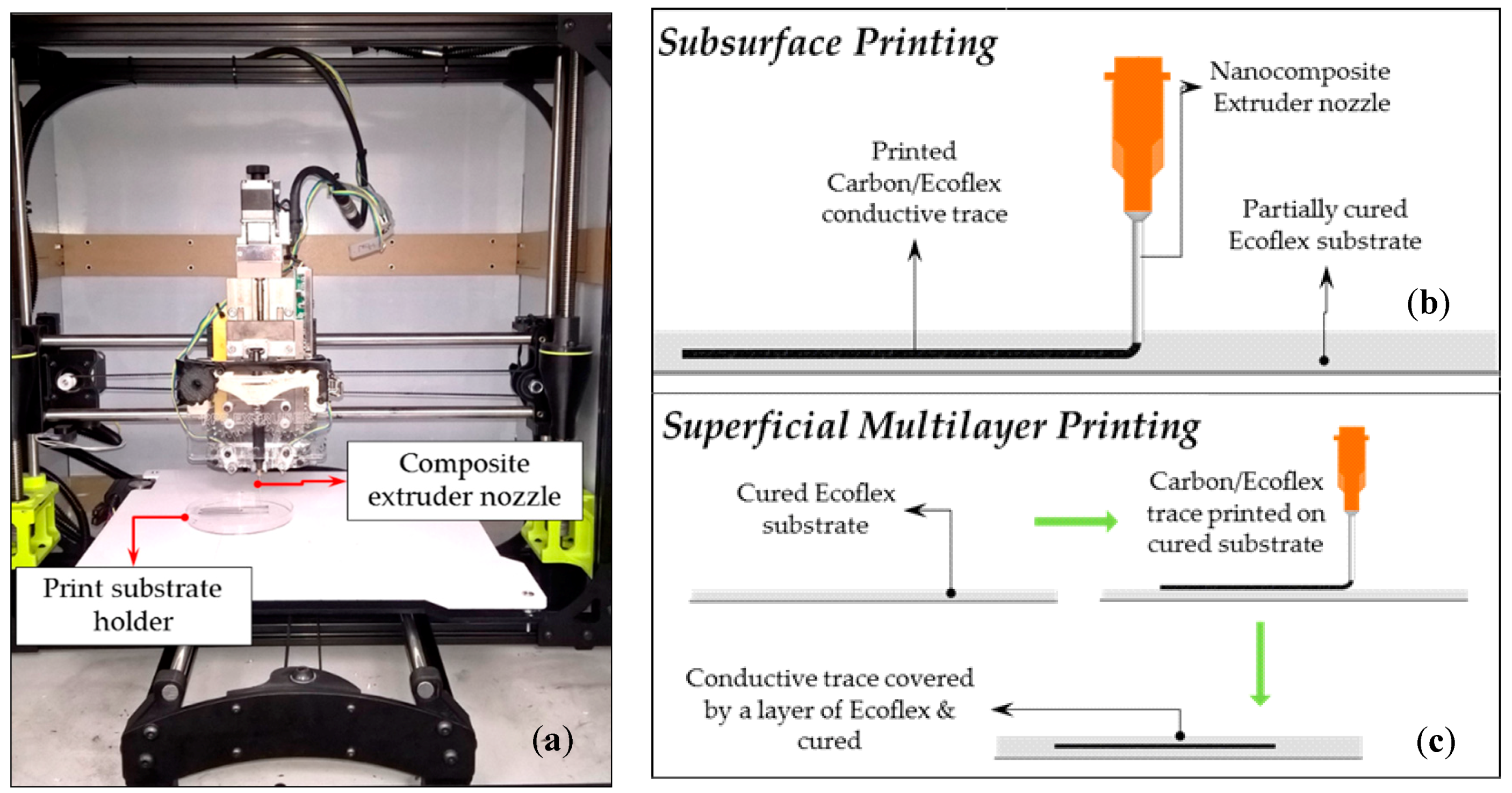
To embed this conductive trace within an Ecoflex layer, two approaches were used: Subsurface printing and superficial multilayer printing. Subsurface printing involves the use of a semi-cured elastomer substrate within which the nozzle is immersed prior to printing at a required height and extruding the carbon-elastomer composite into the elastomer substrate. A schematic representation of the printing process is shown in Figure 2a. Though capable of fabricating reproducible patterns within the semi-cured elastomer substrate, this approach to embed the conductive trace demands a precise curing state of the substrate, i.e., correct viscosity to allow movement of the printer nozzle within the substrate, ability to hold the extruded composite within the subsurface while being still less viscous enough to create continuous an uniformly thin carbon composite traces. The ideal viscosity of the substrate for a continuous deposition should thus be slightly less than that of the composite viscosity. The optimum curing time was found to be 20 min after the two part Ecoflex mixture is mixed before which an acceptable and reproducible pattern within the substrate was possible. While this approach produced a repeatable pattern during printing of MWCNT/Ecoflex composite within semi-cured Ecoflex substrates, printing of CB/Ecoflex and GNP/Ecoflex composites proved to be challenging. While all the prepared composites have similar viscosities relative to that of the substrate viscosity during the time of printing, this difference in printability can be attributed to the nanoparticle morphology. The fibrous morphology of MWCNT allowed continual attachment of the deposited trace to the composite within nozzle creating continuous traces whereas the reduced surface adhesion of Ecoflex between carbon particles in both CB and GNP, due to comparatively lower surface area of these particles and consecutive agglomeration of deposited traces within the semi-cured substrate caused discontinuities.
A superficial multilayer printing approach, to circumvent the drawbacks of subsurface printing using CB and GNP—Ecoflex composites were used to fabricate the stretch sensors. In this approach, a layer of Ecoflex mixture of uniform thickness (equal to half the thickness of the final sensor thickness) was prepared through spin coating at speeds of 200 rpm for 30 s using a Laurell spin coater. This layer was then cured at 80 °C for 5 min after which the conductive composite trace was printed on the top surface of this cured layer. After the printing of the conductive traces, a second layer of Ecoflex was poured to cover this conductive trace and placed in the oven at the same temperature and for the same time as the first layer. The second layer of Ecoflex poured cures and produces a strong and seamless bond with the cured Ecoflex substrate layer thereby embedding the conductive trace completely. Figure 2b schematically represents this printing approach.
While multiple stages are involved in superficial multilayer printing approach, the success rates of printing all the composites and the fabrication time of this approach were preferred for fabrication of stretch sensors. In both approaches, the carbon/elastomer composite was extruded through 21 gauge needles. Blunt tip (probe point type) needles were used to ensure uniform surface tension at the tip of extruder end for a unidirectional extrusion. The obtained traces has a thickness of 1.5 mm and towards determining the printability of any composite, the mass fraction of these composites needs to be predetermined to ensure both printability and conductivity. As printability of these composite materials primarily depend on its viscosity, the optimum viscosity range was to be identified.
2.2. Characterization of Carbon Based Composites
For a composite to be printable, the viscosity of the composite must be lower than a critical value that ensures uninterrupted extrusion with sufficiently low plunger resistance. To identify this critical viscosity, MWCNT/Ecoflex composites with varying mass fractions were initially prepared. Using a Brookfield LV-DV3T rheometer the viscosities of these composites were measured individually and their printability and conductivity were assessed as tabulated in Table 2. It was identified that for the printability of composites, the viscosity should be no more than 115,200 cP. The minimum mass fraction of the MWCNT/Ecoflex composite required, for sufficiently low resistance, and was identified to be 5.26 wt.% of MWCNT.
Towards identifying if the deduced viscosity range can be used to optimize preparation of other printable composites, CB/Ecoflex composited were prepared and their viscosities were measured using the same setup. Unlike the fibrous morphology of MWCNT which provided a larger surface area for attaining percolation thresholds at a lower mass fraction, the particulate nature of CB in the composite demands higher mass fraction of CB in the composite, in order to be conductive. The CB/Ecoflex composite at percolation threshold has a very high levels of viscosity, which was outside the measurement range of the LV-DV3T rheometer, and at lower mass fractions, the CB/Ecoflex composites were less viscous (lower than the critical viscosity), which made them printable. However at this concentration, the composite behaved almost as an insulator with conductivity beyond the useful limits. To improve printability at higher mass fractions, volatile silicone oil, purchased from Wacker Chemie AG, was added to the high mass fraction CB/Ecoflex composites as a dilutant. To remove this volatile silicone oil from the printed traces, once the pattern of the conductive trace is printed, it is then placed in a vacuum desiccator before it is cured. Table 3 summarizes the measured viscosities of the CB/Ecoflex composites. In both Table 2 and Table 3, a “No” for the “Conductivity” columns denotes to the inability of the instrument to record a valid reading.
With the viscosity of the high mass fraction conductive CB/Ecoflex composite modified to be below 115,200 cP, through the addition of volatile silicone oil, it could be used for the successful printing of sensors. Similarly, composites of GNP/Ecoflex were prepared (only GNP in Ecoflex with 20 wt.% or lower had the viscosity low enough to be extruded). Stretch sensors were then prepared from all three composites. All three conductive carbon forms and CB and GNP elastomer composites were analyzed under a scanning electron microscope towards observing the homogeneity and the arrangement of carbon particles within the Ecoflex elastomer matrix. Figure 3 shows a sample large stretch sensor prepared using this printer. Figure 4 shows the SEM images of the CB, MWCNT, and GNP particles and the cut section of CB and GNP-Ecoflex composites. These prepared large stretch sensors are characterized by using a simple stretching rig and the sensors response are discussed.
3. Results
Characterization of the prepared stretch sensors was carried out using a stretching rig, with a precision linear stage used to clamp one end of the sensor and the other end clamped to a rigid fixture. The resistance change to under applied strain was then measured by a Keithley DMM-7510 precision multimeter. Cyclic loading tests were performed on these stretch sensors, stretching them to three times their initial lengths (200% strain) and the response was documented. In order to identify the effect of the applied strain rate on the response of these sensors, the stretching rate was altered and the response compared. Finally, the temperature dependence of these sensors towards understanding the conduction mechanism were also studied.
3.1. Subsection
The prepared stretch sensor samples, with a conductive trace length of approximately 205 mm, were held in-between a fixed and moving clamp controlled by a precision linear stage (Figure 5). The samples are held in such a way that the active strain sensing area is free from any constraints with the extended trace leads, at either end of the pattern, clamped into the fixed side of the stretch rig and connected to the multimeter. The carbon nanoparticle–elastomer composite large stretch sensors fabricated were tested up to 300% strains owing to the limitation of the maximum range of the stretching rig used. To understand the variation of the developed sensor’s GF over varying mass fractions of carbon composites, strain sensors with varying MWCNT, CB, or GNP loadings were also analyzed.
Figure 6 shows the response of stretch sensor made from MWCNT/Ecoflex for strains up to 80%, which was replotted from References [4,26].
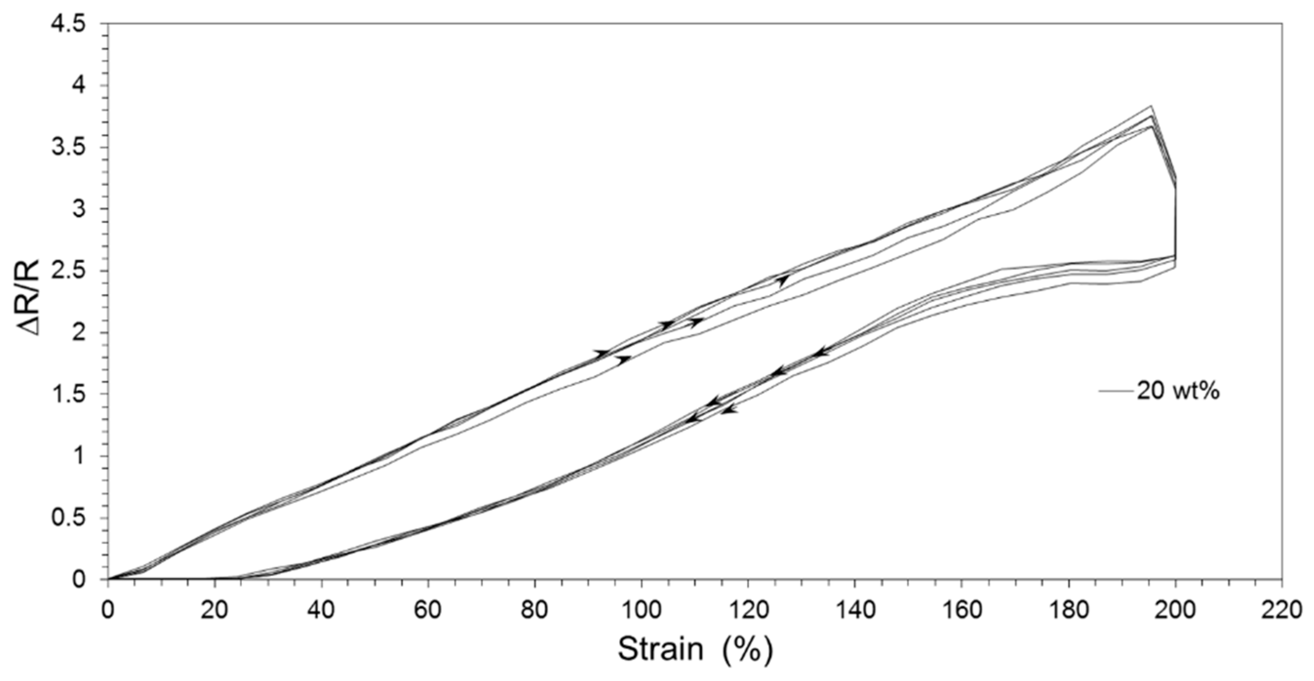
Figure 7 shows the response of CB/Ecoflex based stretch sensor under a strain of 250% for CB mass fractions of 12.5, 15.3, 16.7, and 20 wt.% over multiple strain cycles. From the response of sensors it was observed that the maximum GF was obtained for the composite mass fraction of 16.7 wt.% above which the GF started to drop. This could be attributed to the decreased inter-particle distance and concentration of the conductive CB reaching saturation value providing a better conductivity even at higher strains. The response of this CB/Ecoflex composite, as opposed to the response from MWCNT/Ecoflex composite [4,26], shows a higher GF at much lower strains, albeit with higher hysteresis. The sensor response was fairly linear (R2 ≈ 0.95 across different CB/Ecoflex composite mass fractions). Furthermore, it was observed that the printed large stretch sensors provide a similar response at different mass fractions with a similar hysteresis curve, which can be used to develop a numerical model for compensating this behavior in real life applications.
The same experimental setup was used for studying the response of GNP/Ecoflex composite as piezoresistive material. Note that only sensors with mass fractions of 20% and 16.6% were prepared for the GNP/Ecoflex. The response for 20% is shown in Figure 8. While the CB and MWCNT based composites showed a smooth response during the relaxation stage of the loading cycle, there was a steep change in the resistance just as the strain on the GNP based sensor started to reduce. Furthermore, with a higher GF due to increase in distance between two agglomerated particles, the hysteresis of this sensor (38.8% for 16.7 wt.% and 32% for 20 wt.%) is much larger than that of the hysteresis of CB/Ecoflex sensor.
As we hope to reduce or phase out use of MWCNT in our research group due to the reported harmful effects of this material [14,20], it is helpful to compare sensors based on CB and GNP. The GF and hysteresis for CB/Ecoflex and GNP/Ecoflex composite based sensors together with the previous work on MWCNT, which are tabulated in Table 4. It should be noted that among these carbon based large stretch sensors, the GNP/Ecoflex composites were observed to exhibit the highest hysteresis, while those with MWCNT have the lowest GF
3.2. Sensor Response at Varying Strain Rates
As flexible large stretch sensors can be used in a wide range of applications, which might demand accurate measurement of strain levels at different strain rates, it becomes essential to characterize the difference in the sensors response when tested at different stretching speeds. The sensors were stretched at varying speeds and their response is plotted in Figure 9. It was observed that the GF for all sensors are affected with different stretching rates. However, those with CB and GNP are more sensitive to different stretching rate than those with MWCNT. This is due to the fact that MWCNTs are tubular/fibrous and constantly allow electrical conductivity between the nanotubes as they slide along each other in the direction of applied strain as opposed to CB or GNP.
3.3. Temperature vs. Conductivity of the Sensors
Towards characterizing the sensor’s behavior to changes in temperature for CB and GNP based composites, the change in conductivity of these sensors with respect to temperature variation was experimentally studied. While the MWCNT/Ecoflex based sensor was shown to follow a Mott variable range hopping model (VRH), model from References [4,27,28], with a R2 of 0.987. With the fibrous carbon morphology allowing increased conductivity at higher temperatures, the conduction mechanism in CB/Ecoflex and GNP/Ecoflex based composites could be more complex.
The CB/Ecoflex and GNP/Ecoflex composite based large stretch sensors were placed in a temperature controlled environment and change their resistances as the temperature was increased from room temperature (22 °C) up to 150 °C, which showed a decreasing resistances. To identify the mode of conduction at higher temperatures, the response of these composites were studied against three conduction models, namely Poole-Frenkel, thermionic emission, and Mott-VRH models [29,30,31] (Figure 10).
While the spherical morphology of CB in the composite would demand the sensor response to temperature to follow a thermionic emission model [32], it was observed that this composite closely followed the Mott-VRH model (R2 of 0.9644), similar to that of the characteristics of MWCNT/Ecoflex composite [4], while the large agglomerated GNP in the composite, observed thermionic emission (R2 of 0.9923). Hence, the sensor made from these carbon-based composites could thus be adjusted against their respective models to compensate for the resistance variation at different temperatures. However, the understanding of charge transport mechanisms is beyond the scope of this article. Nevertheless, the analyses of changes in resistance with temperature could be used to compensate for resistance drift over the temperature in real life applications.
3.4. Preliminary Testing on Robotic Hand Exoskeleton
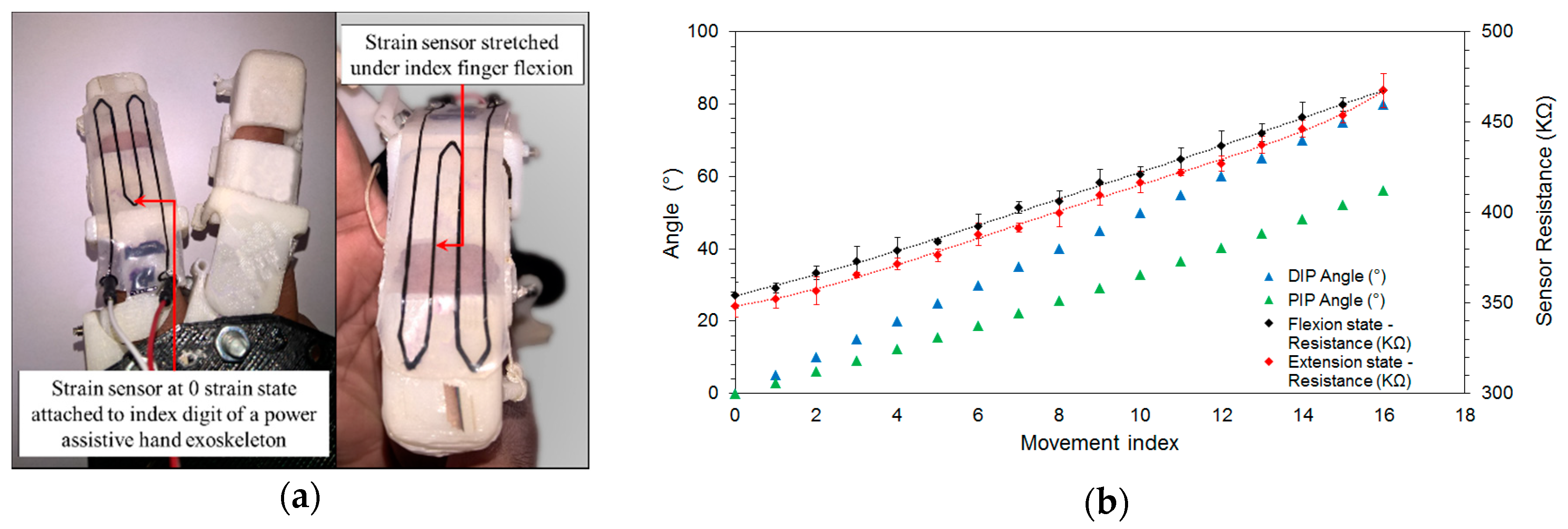
To identify the suitability of implementing the printed CB/Ecoflex composite sensors in real world applications, preliminary tests was carried out with the power-assistive hand exoskeleton (Figure 1b) integrated with the large strain sensor as shown in Figure 11a. The two wires (Figure 11a) connect the strain sensor output to a Keithley DMM 7510 precision multimeter which is in-turn connected to the PC to record the resistance output via Keithley Kickstart software. To simulate a full range of finger motion, the exoskeleton finger joint angles are preprogrammed to corresponding expansion of pneumatic actuators through LabVIEW interface. Each movement index takes the finger from fully extended state (distal interphalangeal (DIP) and proximal interphalangeal joint (PIP) angles, both at 0°, to a fully flexed state (DIP and PIP angles at 80° and 56.2°, respectively) in discrete steps. For ease of understanding, the sensor response is measured with respect to these discrete movement indices (each discrete step taking 125 ms) and the corresponding pre-set DIP and PIP angles are also shown in Figure 11b.
Three flexion and extension cycles were carried out with the CB/Ecoflex strain sensor’s resistance varying as shown in Figure 11b. The observed hysteresis was comparatively less than those observed in testing on the simulation rig. The lesser strain applied on the sensor was due to finger flexion inducing smaller amounts of hysteresis in the sensor output. Further testing on individual tests to characterize and calibrate the sensor is beyond the scope of this article.
4. Discussion & Conclusions
Flexible large stretch sensors based on carbon-based elastomer composites were studied and show notably different performance even though they are all carbon based. Though MWCNT based elastomer composites boast desirable response (high conductivity and low hysteresis) with a low mass to Ecoflex loading, as expected these sensor have comparatively low GF. This was primarily attributed to the MWCNT fibrous structure, which allows the strands of MWCNTs to slide relatively along the direction of strain while still maintaining close proximity to adjacent strands. The relatively high GF of CB/Ecoflex and GNP/Ecoflex composite based sensors could be similarly explained by their particular morphology. As the strain increases, the increased inter-particle distance increases the distance through which the electrons have to hop through the dielectric elastomer and in-turn increase the resistance of the composite appreciably. While the GF of GNP based sensors was similar to that of CB based sensors, the large hysteresis of the GNP based sensors (over 150%) made them unattractive. However, it should be noted that limited experiments (20% and 16.67% mass fractions) were conducted on GNP/Ecoflex sensors. Nevertheless, CB based sensors demonstrated in this work had comparable performance to the MWCNT-based sensors (although the hysteresis is approximately double that with MWCNT), implying that the potential carcinogenic hazard of handling MWCNT during preparation of these stretch sensors could perhaps be circumvented by replacing this material with CB.
Large stretch sensors that can measure strains up to at least 200% were prepared from multiple carbon based elastomer nano-composites using a printing technique and their response was characterized. The printability of these composites was also studied by analyzing the viscosities of the materials, which allows estimating printability of composites prior to the actual printing process. By using computer controlled printing of these materials, more complex patterns can be created, improving the sensor’s applicability in a wide variety of potential applications ranging from wearable devices to medical soft robots. The difference in the sensor response (gauge factor, hysteresis, the effect of strain rate, and temperature dependence) among these carbon-based composites have been examined, and among these, the CB based composites were considered to be the material of choice for implementation in robotic applications.
Author Contributions
Conceptualization, H.D., T.G. and K.A.; Methodology, H.D. and T.G.; Software, H.D. and T.G.; Validation, H.D., T.G. and A.P.; Formal Analysis, H.D. and A.P.; Investigation, A.P.; Data Curation, A.P. and M.A.; Writing-Original Draft Preparation, H.D. and A.P.; Writing-Review & Editing, T.G. and K.A.; Supervision, T.G. and K.A.; Project Administration, K.A.
Funding
This research received no external funding.
Conflicts of Interest
The authors declare no conflict of interest.
References
- Do, C.D.; Erbes, A.; Yan, J.; Soga, K.; Seshia, A.A. Vacuum packaged low-power resonant mems strain sensor. J. Microelectromech. Syst. 2016, 25, 851–858. [Google Scholar] [CrossRef]
- Baptist, J.R.; Zhang, R.; Wei, D.; Saadatzi, M.N.; Popa, D.O. Fabrication of strain gauge based sensors for tactile skins. In Proceedings of the SPIE Commercial + Scientific Sensing and Imaging, Anaheim, CA, USA, 22 May 2017. [Google Scholar]
- Jia, Y.; Do, C.D.; Zou, X.; Seshia, A.A. A hybrid vibration powered microelectromechanical strain gauge. IEEE Sens. J. 2016, 16, 235–241. [Google Scholar] [CrossRef]
- Giffney, T.; Bejanin, E.; Kurian, A.S.; Travas-Sejdic, J.; Aw, K. Highly stretchable printed strain sensors using multi-walled carbon nanotube/silicone rubber composites. Sens. Actuators A Phys. 2017, 259, 44–49. [Google Scholar] [CrossRef]
- Cai, L.; Song, L.; Luan, P.; Zhang, Q.; Zhang, N.; Gao, Q.; Zhao, D.; Zhang, X.; Tu, M.; Yang, F. Super-stretchable, transparent carbon nanotube-based capacitive strain sensors for human motion detection. Sci. Rep. 2013, 3, 3048. [Google Scholar] [CrossRef] [PubMed]
- Yao, S.; Zhu, Y. Wearable multifunctional sensors using printed stretchable conductors made of silver nanowires. Nanoscale 2014, 6, 2345–2352. [Google Scholar] [CrossRef] [PubMed]
- Amjadi, M.; Kyung, K.U.; Park, I.; Sitti, M. Stretchable, skin-mountable, and wearable strain sensors and their potential applications: A review. Adv. Funct. Mater. 2016, 26, 1678–1698. [Google Scholar] [CrossRef]
- Choi, D.Y.; Kim, M.H.; Oh, Y.S.; Jung, S.-H.; Jung, J.H.; Sung, H.J.; Lee, H.W.; Lee, H.M. Highly stretchable, hysteresis-free ionic liquid-based strain sensor for precise human motion monitoring. ACS Appl. Mater. Interfaces 2017, 9, 1770–1780. [Google Scholar] [CrossRef] [PubMed]
- Yildiz, S.K.; Mutlu, R.; Alici, G. Fabrication and characterisation of highly stretchable elastomeric strain sensors for prosthetic hand applications. Sens. Actuators A Phys. 2016, 247, 514–521. [Google Scholar] [CrossRef]
- Keulemans, G.; Ceyssens, F.; Puers, R. An ionic liquid based strain sensor for large displacement measurement. Biomed. Microdevices 2017, 19, 1. [Google Scholar] [CrossRef] [PubMed]
- Yoon, S.G.; Koo, H.-J.; Chang, S.T. Highly stretchable and transparent microfluidic strain sensors for monitoring human body motions. ACS Appl. Mater. Interfaces 2015, 7, 27562–27570. [Google Scholar] [CrossRef] [PubMed]
- Yamada, T.; Hayamizu, Y.; Yamamoto, Y.; Yomogida, Y.; Izadi-Najafabadi, A.; Futaba, D.N.; Hata, K. A stretchable carbon nanotube strain sensor for human-motion detection. Nat. Nanotechnol. 2011, 6, 296–301. [Google Scholar] [CrossRef] [PubMed]
- Costa, P.; Silva, J.; Ansón-Casaos, A.; Martinez, M.; Abad, M.; Viana, J.; Lanceros-Mendez, S. Effect of carbon nanotube type and functionalization on the electrical, thermal, mechanical and electromechanical properties of carbon nanotube/styrene–butadiene–styrene composites for large strain sensor applications. Compos. Part B Eng. 2014, 61, 136–146. [Google Scholar] [CrossRef] [Green Version]
- Ryu, S.; Lee, P.; Chou, J.B.; Xu, R.; Zhao, R.; Hart, A.J.; Kim, S.-G. Extremely elastic wearable carbon nanotube fiber strain sensor for monitoring of human motion. ACS Nano 2015, 9, 5929–5936. [Google Scholar] [CrossRef] [PubMed]
- Roh, E.; Hwang, B.-U.; Kim, D.; Kim, B.-Y.; Lee, N.-E. Stretchable, transparent, ultrasensitive, and patchable strain sensor for human–machine interfaces comprising a nanohybrid of carbon nanotubes and conductive elastomers. ACS Nano 2015, 9, 6252–6261. [Google Scholar] [CrossRef] [PubMed]
- Foroughi, J.; Spinks, G.M.; Aziz, S.; Mirabedini, A.; Jeiranikhameneh, A.; Wallace, G.G.; Kozlov, M.E.; Baughman, R.H. Knitted carbon-nanotube-sheath/spandex-core elastomeric yarns for artificial muscles and strain sensing. ACS Nano 2016, 10, 9129–9135. [Google Scholar] [CrossRef] [PubMed]
- Liu, Y.; Zhao, Y.; Sun, B.; Chen, C. Understanding the toxicity of carbon nanotubes. Acc. Chem. Res. 2012, 46, 702–713. [Google Scholar] [CrossRef] [PubMed]
- Toyokuni, S. Genotoxicity and carcinogenicity risk of carbon nanotubes. Adv. Drug Deliv. Rev. 2013, 65, 2098–2110. [Google Scholar] [CrossRef] [PubMed]
- Rittinghausen, S.; Hackbarth, A.; Creutzenberg, O.; Ernst, H.; Heinrich, U.; Leonhardt, A.; Schaudien, D. The carcinogenic effect of various multi-walled carbon nanotubes (mwcnts) after intraperitoneal injection in rats. Part. Fibre Toxicol. 2014, 11, 59. [Google Scholar] [CrossRef] [PubMed]
- Kim, M.S.; Kwon, D.; Kim, S.; Kim, K.; Park, I. Surface micro-structured, stretchable strain sensor towards biaxial sensitivity and performance enhancement. In Proceedings of the 2017 IEEE 30th International Conference on Micro Electro Mechanical Systems (MEMS), Las Vegas, NV, USA, 22–26 January 2017; pp. 1044–1047. [Google Scholar]
- Helbling, T.; Hierold, C.; Roman, C.; Durrer, L.; Mattmann, M.; Bright, V. Long term investigations of carbon nanotube transistors encapsulated by atomic-layer-deposited Al2O3 for sensor applications. Nanotechnology 2009, 20, 434010. [Google Scholar] [CrossRef] [PubMed]
- Gammelgaard, L.; Rasmussen, P.A.; Calleja, M.; Vettiger, P.; Boisen, A. Microfabricated photoplastic cantilever with integrated photoplastic/carbon based piezoresistive strain sensor. Appl. Phys. Lett. 2006, 88, 113508. [Google Scholar] [CrossRef] [Green Version]
- Xia, H.; Wang, Q.; Qiu, G. Polymer-encapsulated carbon nanotubes prepared through ultrasonically initiated in situ emulsion polymerization. Chem. Mater. 2003, 15, 3879–3886. [Google Scholar] [CrossRef]
- Yamamoto, M.; Witt, U.; Skupin, G.; Beimborn, D.; Müller, R.J. Biodegradable aliphatic-aromatic polyesters: “Ecoflex®”. Biopolym. Online 2005, 4. [Google Scholar] [CrossRef]
- Chossat, J.-B.; Shin, H.-S.; Park, Y.-L.; Duchaine, V. Soft tactile skin using an embedded ionic liquid and tomographic imaging. J. Mech. Robot. 2015, 7, 021008. [Google Scholar] [CrossRef]
- Kurian, A.S.; Giffney, T.; Lee, J.; Travas-Sejdic, J.; Aw, K.C. Printing of cnt/silicone rubber for a wearable flexible stretch sensor. In Proceedings of the SPIE Conference on Electroactive Polymer Actuators and Devices (EAPAD), Las Vegas, NV, USA, 21–24 March 2016. [Google Scholar]
- Vasanthkumar, M.; Bhatia, R.; Arya, V.P.; Sameera, I.; Prasad, V.; Jayanna, H. Characterization, charge transport and magnetic properties of multi-walled carbon nanotube–polyvinyl chloride nanocomposites. Phys. E Low-Dimens. Syst. Nanostruct. 2014, 56, 10–16. [Google Scholar]
- Mott, N. Conduction in Non-Crystalline Materials; Oxford University Press: Oxford, UK, 1993; p. 157. [Google Scholar]
- Arya, V.P.; Prasad, V.; Kumar, P.A. Effect of magnetic field on mott’s variable-range hopping parameters in multiwall carbon nanotube mat. J. Phys. Condens. Matter 2012, 24, 245602. [Google Scholar] [CrossRef] [PubMed]
- Sheng, P.; Sichel, E.; Gittleman, J.I. Fluctuation-induced tunneling conduction in carbon-polyvinylchloride composites. Phys. Rev. Lett. 1978, 40, 1197. [Google Scholar] [CrossRef]
- Chin, S.J.; Vempati, S.; Dawson, P.; Knite, M.; Linarts, A.; Ozols, K.; McNally, T. Electrical conduction and rheological behaviour of composites of poly (ε-caprolactone) and mwcnts. Polymer 2015, 58, 209–221. [Google Scholar] [CrossRef]
- Choy, T.; Harker, A.; Stoneham, A. Field emission theory for an enhanced surface potential: A model for carbon field emitters. J. Phys. Condens. Matter 2004, 16, 861. [Google Scholar] [CrossRef]
Figure 1.
The use of flexible large stretch sensors in (a) robotic/prosthetic hand and (b) power-assistive hand exoskeleton.
Figure 1.
The use of flexible large stretch sensors in (a) robotic/prosthetic hand and (b) power-assistive hand exoskeleton.

Figure 2.
(a) The nano-composite printer and the printing methods employed (b) Subsurface printing of conductive composite trace in elastomer matrix and (c) superficial multilayer printing approach for preparation of large stretch sensor.
Figure 2.
(a) The nano-composite printer and the printing methods employed (b) Subsurface printing of conductive composite trace in elastomer matrix and (c) superficial multilayer printing approach for preparation of large stretch sensor.

Figure 3.
A sample flexible large stretch sensor prepared using superficial multilayer printing using CB—Ecoflex composite.
Figure 3.
A sample flexible large stretch sensor prepared using superficial multilayer printing using CB—Ecoflex composite.

Figure 4.
SEM images of (a) CB particles, (b) fractured CB/Ecoflex composite showing CB particles distributed in the elastomer matrix, (c) MWCNT, and (d) GNP/Ecoflex composite showing agglomeration of GNP within the elastomer matrix.
Figure 4.
SEM images of (a) CB particles, (b) fractured CB/Ecoflex composite showing CB particles distributed in the elastomer matrix, (c) MWCNT, and (d) GNP/Ecoflex composite showing agglomeration of GNP within the elastomer matrix.

Figure 5.
The stretching rig that applies varying levels of strain at controlled rates to the fabricated 3D printed piezoresistive stretch sensors.
Figure 5.
The stretching rig that applies varying levels of strain at controlled rates to the fabricated 3D printed piezoresistive stretch sensors.

Figure 6.
MWCNT/Ecoflex sensor response at a mass fraction of 6.25% under applied strains of up to 80%.
Figure 6.
MWCNT/Ecoflex sensor response at a mass fraction of 6.25% under applied strains of up to 80%.

Figure 7.
CB/Ecoflex sensor response at different composite mass fractions (for one loading cycle and arrows indicating directions of loading and unloading) up to a strain of 250%.
Figure 7.
CB/Ecoflex sensor response at different composite mass fractions (for one loading cycle and arrows indicating directions of loading and unloading) up to a strain of 250%.

Figure 8.
GNP/Ecoflex sensor response with GNP of 20% mass fractions (showing five loading cycles) up to a strain of 200%.
Figure 8.
GNP/Ecoflex sensor response with GNP of 20% mass fractions (showing five loading cycles) up to a strain of 200%.

Figure 9.
Sensor response of carbon elastomer composites stretch sensors at varying strain rates.

Figure 10.
Temperature variance of printed trace resistance for (a) CB/Ecoflex and (b) GNP/Ecoflex composite and their fit to the respective conduction models.
Figure 10.
Temperature variance of printed trace resistance for (a) CB/Ecoflex and (b) GNP/Ecoflex composite and their fit to the respective conduction models.

Figure 11.
(a) Integration scheme of CB/Ecoflex sensor on the digits of a hand exoskeleton and (b) response of sensor over 3 flexion/extension cycles.
Figure 11.
(a) Integration scheme of CB/Ecoflex sensor on the digits of a hand exoskeleton and (b) response of sensor over 3 flexion/extension cycles.


Table 1.
Characteristics of large strain sensor’s recently demonstrated.
| Work of | Sensor Material | GF | Strain Range (%) | Reference |
|---|---|---|---|---|
| Costa et al. | CNT in SBS | 2–6 | 5 | [13] |
| Roh et al. | CNT in Pu-PEDOT:PSS | 62 | 100 | [15] |
| Ryu et al. | CNT fiber spun in Ecoflex | 0.24–64 | 200–900 | [14] |
| Yamada et al. | CNT on PDMS | 0.125 | 280 | [12] |
| Foroughi et al. | CNT composite in Spandex | 0.12–0.4 | 80 | [16] |
| Yoon et al. | Ionic liquid | 40 | 200 | [11] |
| Choi et al. | Ionic liquid | 2–4 | 250 | [8] |
| Giffney et al. | CNT in Ecoflex | 1–1.5 | 300 | [4] |
Table 2.
Viscosities and applicability of MWCNT/Ecoflex composites at different mass fractions.
| Composite | Mass Fraction (wt.%) | Viscosity (cP) | Conductivity | Printability |
|---|---|---|---|---|
| MWCNT in Ecoflex | 9.09 | Out of range | Yes | No |
| 7.69 | Out of range | Yes | No | |
| 6.25 | 6,312,000 | Yes | No | |
| 5.56 | 115,200 | Yes | Yes | |
| 5.26 | 110,600 | Yes | Yes | |
| 4.76 | 58,440 | No | Yes |
Table 3.
Viscosities and applicability of CB/Ecoflex composites at different mass fractions.
| Composite | Mass Fraction (wt.%) | Volatile Silicone Oil Added to Composite (wt.%) | Viscosity (cP) | Conductivity | Printability |
|---|---|---|---|---|---|
| CB in Ecoflex | 20.00 | 0 | Out of range | Yes | No |
| 12.50 | 0 | Out of range | Yes | No | |
| 9.09 | 0 | 172,500 | No | Yes | |
| 20.00 | 36.08 | 79,940 | Yes | Yes | |
| 16.67 | 32.87 | 76,000 | Yes | Yes | |
| 15.33 | 22.57 | 74,400 | Yes | Yes | |
| 12.50 | 23.68 | 17,370 | Yes | Yes |
Table 4.
Comparison of stretch sensors made from MWCNT, CB, and GNP.
| Composite | Strain (%) | Mass Fraction (wt.%) | GF | Hysteresis (%) |
|---|---|---|---|---|
| MWCNT/Ecoflex | 200 | 6.25 | 1 | 8 |
| 200 | 5.56 | 1.5 | ||
| CB/Ecoflex | 250 | 20 | 1.63 | 16.4 |
| 250 | 16.7 | 1.75 | 13.7 | |
| 250 | 15.3 | 1.58 | 16.5 | |
| 250 | 12.5 | 1.63 | 12.0 | |
| GNP/Ecoflex | 200 | 20 | 1.72 | 150 |
| 200 | 16.67 | 1.65 | 200 |
© 2018 by the authors. Licensee MDPI, Basel, Switzerland. This article is an open access article distributed under the terms and conditions of the Creative Commons Attribution (CC BY) license (http://creativecommons.org/licenses/by/4.0/).
Share and Cite
MDPI and ACS Style
Devaraj, H.; Giffney, T.; Petit, A.; Assadian, M.; Aw, K. The Development of Highly Flexible Stretch Sensors for a Robotic Hand. Robotics 2018, 7, 54. https://doi.org/10.3390/robotics7030054
AMA Style
Devaraj H, Giffney T, Petit A, Assadian M, Aw K. The Development of Highly Flexible Stretch Sensors for a Robotic Hand. Robotics. 2018; 7(3):54. https://doi.org/10.3390/robotics7030054
Chicago/Turabian StyleDevaraj, Harish, Tim Giffney, Adeline Petit, Mahtab Assadian, and Kean Aw. 2018. "The Development of Highly Flexible Stretch Sensors for a Robotic Hand" Robotics 7, no. 3: 54. https://doi.org/10.3390/robotics7030054
Note that from the first issue of 2016, this journal uses article numbers instead of page numbers. See further details here.