1. Introduction
Static balancing of a mechanical system is one of the first demanding steps in the design process of any mechanical system which is moving with relatively small accelerations and which is overcoming relatively large forces, in order to match first of all the need of energy consumption and it is also an important aspect of the overall performance of it [
1].
Static balancing can be regarded as the total or partial cancellation of the mechanical effects (force or moment) of static loads to the actuating system of mechanical system, in all configurations, respectively in a finite number of configurations, from functioning domain, under quasi-static conditions [
1,
2]. The effect of this action is the maintaining of the mechanical system in a rest state at any configuration or at a finite number of configurations respectively, from working space and its actuators are not required to overcome the static loads. The movement inside working space can be done with a power-less actuating system which consumes energy only for overcoming the friction forces and balancing errors. Anyway the friction forces are opposing to the movement, contributing in this way to the maintaining of the mechanical system in a rest state.
The main static load is given by gravitational field of Earth, which is reflecting into the weight forces of all bodies that compose the mechanical system. In the case that weight forces are the only static loads of static balancing operation then the mechanical system is called gravity compensate. Also the effect of these loads to the actuating system is present only in the case that the mechanical system is not working in horizontal plane with respect to gravity field.
Consequently, the potential energy of mechanical system remains constant or approximately constant and the centre of gravity of mechanical system remain fixed with respect to a referential frame or is moving along a horizontal direction or into a horizontal plane with respect to Earth.
Another important observation and hypothesis is that due to the small displacements of the centres of gravity of elements, with respect to the distance from the centre of the Earth to each body mass centres, then the weight forces are constant.
In this case the actuators of mechatronic system are not required to sustain the weight of its moving elements.
But, in the case of a manipulation robot for example, as is also the case of cranes too, the manipulation weight could be variable in steps. As is presented in article [
3] for the case of an industrial robot [
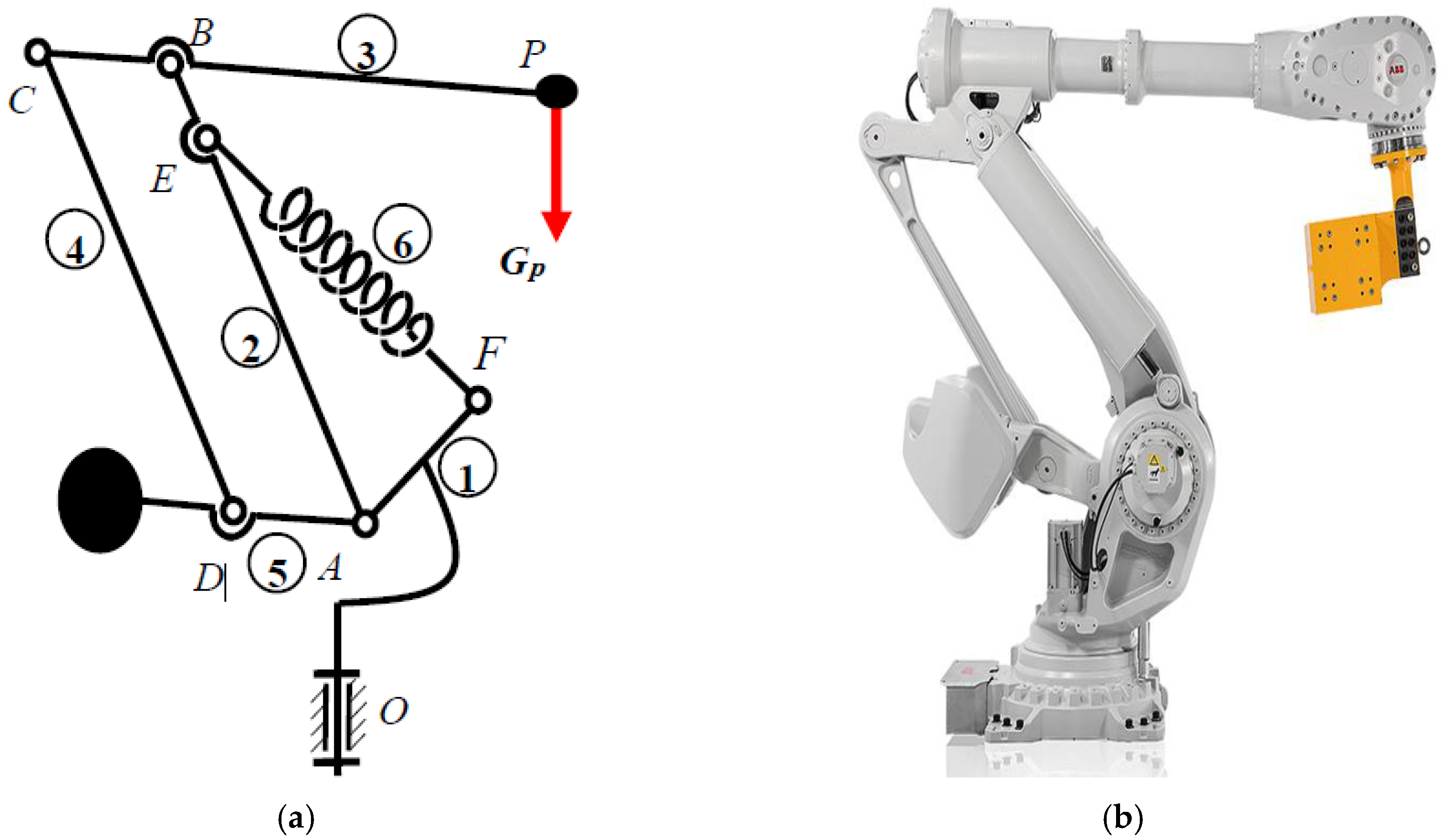
4] which is designed to manipulate payloads of 16 kg maximum mass, balanced by springs for a middle weight mass of 8 kg, the forces induced in actuating system are amplified about 4 times when the weight is increasing or decreasing from the mean value. In fact, in terms of resistance moments (torques) at shafts of rotating actuators, as is shown in
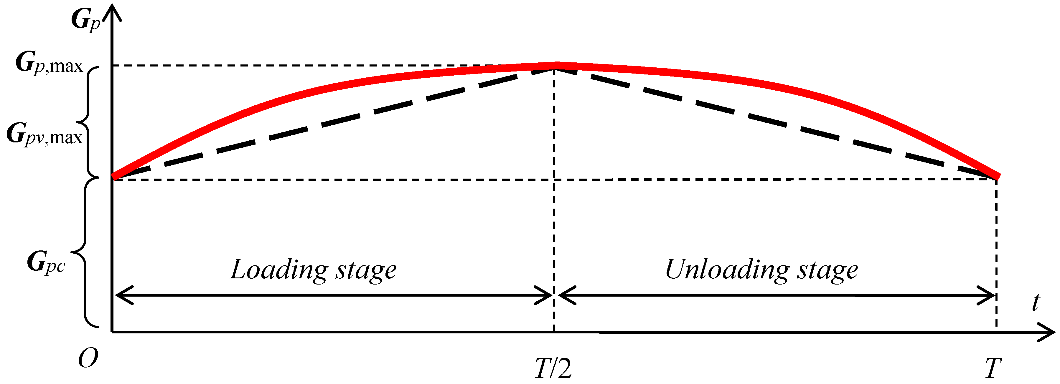
Figure 1a for the most frequent case of an articulated arm, this variation occurs (and has a cosine variation) even the payload has constant weight
Gp. In case the load has variable weight (as is the case of oil pump-jack systems for example [
5] then a more complex variation is possible (
Figure 1b—solid curve line 1). A special situation is the one when the variation is known, and it is repeating during one cycle. In this case the adaptive solution could be a passive one (i.e., not actuated). Otherwise the balancing system should adapt in real time by using a local and supplementary actuation system and by aid of a controlling system and the required sensors and transducers [
2].
Many other mechanical systems, which are automatized more and more in these days, becoming in this way mechatronic systems, have to overcome variable payloads or resistant forces during the functioning. Beside the manipulation robots used in palletizing for example [
5,
6,
7,
8,
9], articulated cranes [
10,
11,
12] and pump-jack oil pumps [
13,
14,
15], a large category of ergonomic manipulators [
16,
17,
18] are facing the variable payload and have to adapt to this condition.
By balancing, another moment which is opposing the load moment (
Figure 1b—dotted curve line 2) should be induced in order to compensate or eliminate the effect of load. If the difference between the load moment and the balancing moment is zero, then the system is perfect (exact) balanced in all positions from its work field [
19]. If there are only some positions where the difference is zero (
Figure 1b—discontinuous curve line 3) then an approximate balancing is obtained [
20].
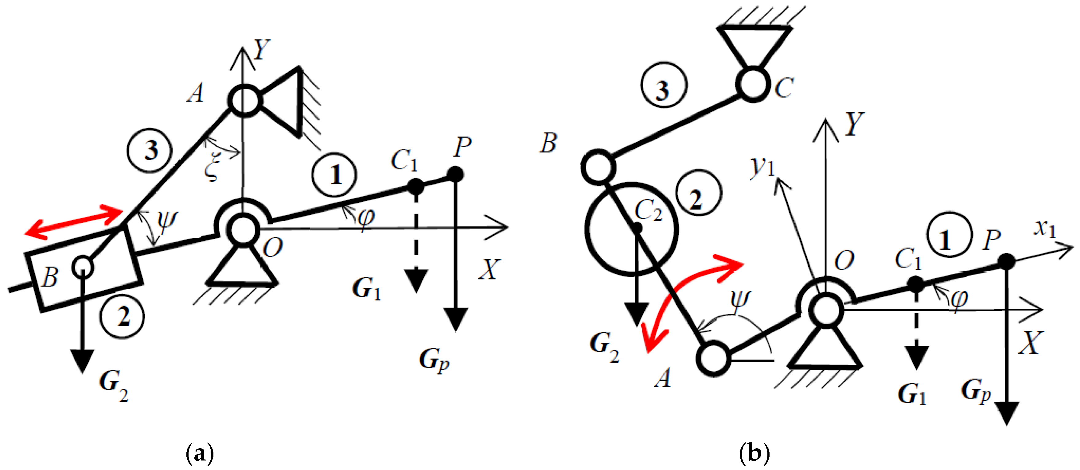
In order to compensate the effects of static loads that depend to displacements, then forces which depend also to displacements should be used. The main candidates are the weight forces represented by counterweights and the elastic forces of springs or gases. Industrial robots are using both of these solutions (
Figure 2) for example ABB industrial robot of IRB 6499 RF model [
6].
Even in the case of static balancing by using counterweights the overall mass of the mechanical system is increased and from dynamics point of view the situation could become worse than in the case the mechanical system is even unbalanced, this solution is still useful and widely used in engineering because of the simplicity and for mechanical systems which are manipulating large loads, and which are operating at low or moderate dynamics.
As for the adaptation to the variation of the payload in case of robots and automatized mechanical systems many ideas are proposed in scientific papers or patents passed years [
2,
21,
22,
23,
24] but no realization in practice for these domains. If there are some adjustments in order to adapt to the variation of payload they are made off-line [
6,
9,
21] while mechatronic system is in a rest state. On the other hand if the variation is not very large then an approximate simple solution is solving the problem in practice. Anyway the difficulty of static balancing comes from the variation of the payload and in the case of spatial mechanisms of robots or other mechatronic systems became more difficult due to the complexity of the movements.
2. Adaptive Balancing by Using Counterweights
The method of adding the counterweights involves the increasing of moving masses, overall size, inertia and the stresses of the mechanism links [
20]. Some of the mechanical systems [
1] accept this method because of operating at low or moderate dynamics, from safety reasons or in cases where the right spring is difficult and costly to be obtained [
2], or the spring balancing solution is too complicated to be fitted to [
25]. Anyway, an internal mass redistribution so that parts of mechanical systems (actuators, electric motors, other mechanical transmission, either electric or electronic parts from controlling cabinet which could be relocated on the robot body) to act as counterweights like in the case of industrial robots [
9], or as is the case of camera stabilizers [
26], is first step when the static balancing problem starts [
2].
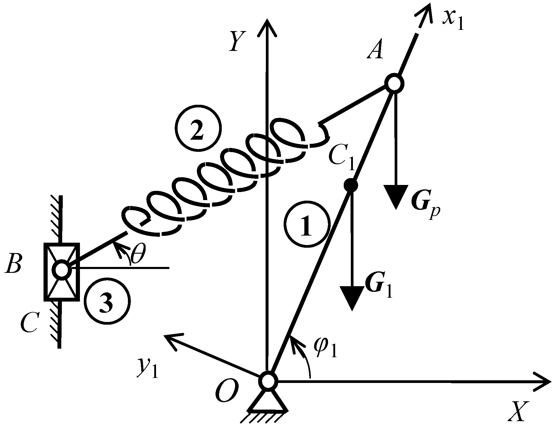
Variation of gravitational moment given by the weight force of the rocking arm ① (
Figure 1a)
G1 and by the variable payload
Gp has the expression:
where:
with:
Then the balancing moment should be:
so that:
Let suppose the case of the rocking arm ① which is gravity compensated for its weight
G1 and for the weight of the constant part from the variation of payload
Gpc (
Figure 3) by a counterweight mounted fixed on the rocking arm ① at a proper distance on the opposite side then centre of mass
C1 according to origin point
O (not represented in the following). In this case the constant
c1 from Relation (3) became:
A variation of static load in linear form (as is represented in
Figure 3—dashed line) was studied in Reference [
25] and will be taken as comparison in Example section. By taking into consideration some frictions in the mechanical system of payload let suppose the variation of payload is known and cyclic with a symmetric variation of second degree evolution during one period of time
T (
Figure 3):
In order to gravity compensate the variable component Gpv by using also a supplementary counterweight then 2 possibilities could be taken into consideration: a variable weight of the additional counterweight or a movable counterweight with a fixed weight.
To make a variable weight for the counterweight is not impossible but is complicated and in order to compensate a continuous variation then liquid weights are needed, which are complicating much more the system and the dynamics became also very important. From practical point of view the changing of the location of the additional counterweight on the balanced element (as is the studied rocking arm ① in
Figure 1a) is a feasible solution when the speeds and accelerations are not very high.
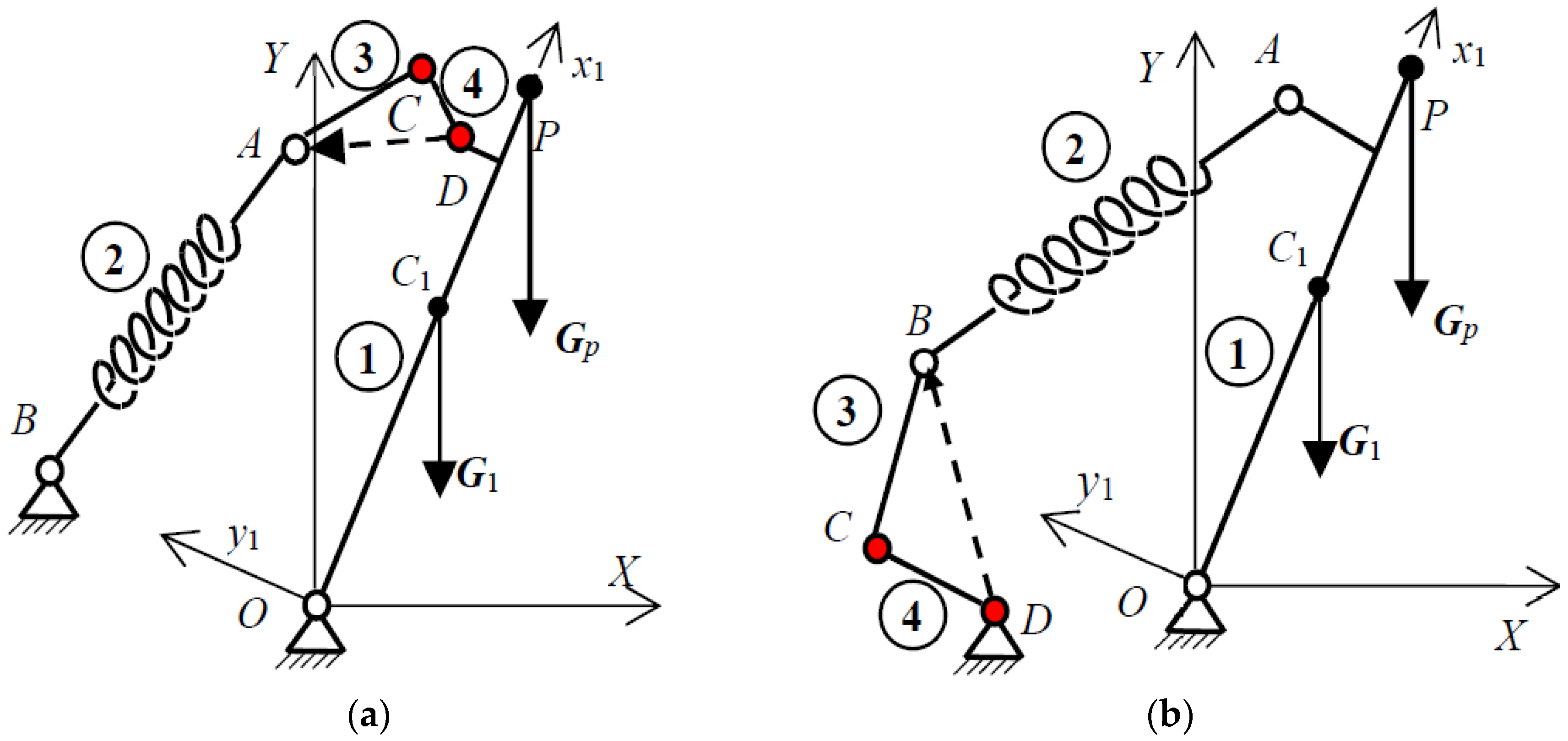
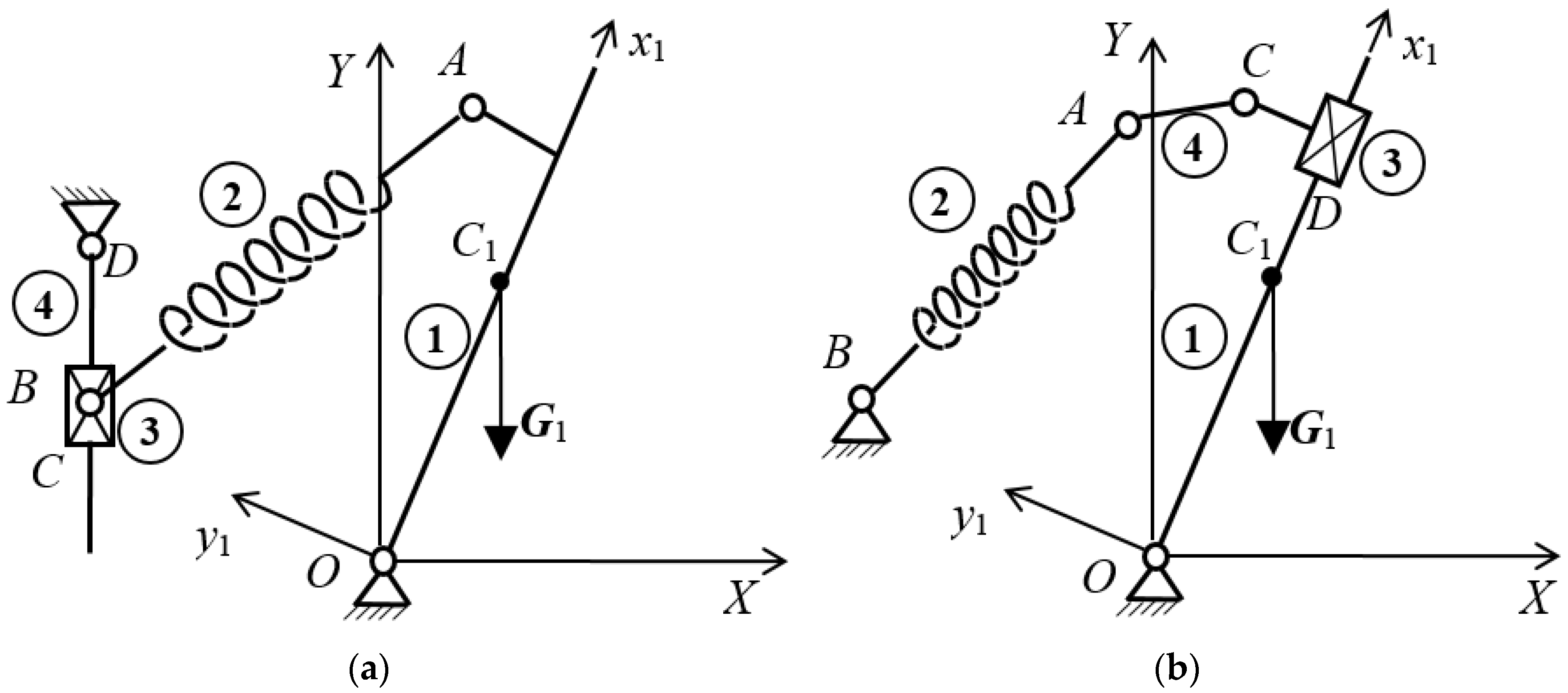
There are also 2 possible ways of moving the additional counterweight ② relatively to the balanced element: by translating onto it (
Figure 4a without bar ③) or by rotating around a point which is becoming a joint on it by using an additional bar (
Figure 4b without bar ③).
Despite of the pretentious prismatic joint the solution with translating counterweight became very popular [
4,
15] due to the better dynamics of the multi-body system and due to the simplicity of the transmission of the supplementary actuator.
In case of a known cyclic variation of payload, as it is represented in
Figure 3, then a passive adaptive solution is possible to be used that is, a solution which does not require supplementary energy added from the outside of the mechanical system. The simplest solution is presented in Reference [
15] by linking the counterweight ② to the mechanism base through a simple bar denoted by ③ and connected by two joints as is shown in
Figure 4a.
In
Figure 4a is presented the symmetric solution which is leading to a reduced number of exact balancing positions (maximum three). In this case the gravitational moment which has to be compensated is:
where:
and:
The balancing moment
Mb of counterweight ② has the expression:
where in the weight
G2 could be count as added the part of the weight of the connecting bar ③ concentrated in point
B because is fixed one (
Figure 3a).
The position of the counterweight on the balanced arm ① has the expression:
or:
where:
Unbalancing moment
Mu is given by relation:
and by comparing relations (12) and (13) with (8)–(11) is obvious that unbalancing cannot be zero which is anyway shown in Example section. But the unbalancing is better than in the case of linear variation of payload at the same conditions.
As for the solution from
Figure 4b, with the rocking counterweight, the balancing is also approximate. The position of bar
BC with respect to reference system
XOY has a more complicated form (resulted by the solving of positional kinematics of
RRR dyad composed by elements
AB and
BC) because it depends to:
- -
the position of points A and B;
- -
the length of bars BC and AB.
Analytic solving (and numerical one too [
27]) leads to two mathematical solutions from kinematics but only one is correct from balancing point of view, the one when
π/2 < |
ψ| <
π.
General and non-symmetric solution from
Figure 4b requires an optimization solving too with following design variables:
- -
coordinates of points A(x1A, y1A) and C(XC, YC);
- -
lengths of connecting bars AB and BC;
- -
position AC2 of the counterweight on the bar ② and the mass of the counterweight m2.
3. Adaptive Balancing by Using Springs
There are many papers and patents [
1,
2] which studied during the time the problem of static balancing by using springs. Most of them consider the problem when the static load is constant and more of that do not take into consideration the spring mass. In any case the simplest and general solution of articulating a spring between the balanced arm and the ground (
Figure 5) is leading to an approximate solution [
20].
In this way a better idea is to join the spring to the balanced arm so that its weight concentrated in the joint to act as a counterweight too (
Figure 5). But as is wrote in many papers and even from the beginning started by Carwardine [
28], the solution from
Figure 5 requires zero-free-length springs [
25] or zero-free-length elastic systems [
29].
One of the solution is to remove one of the spring joints and to intercalate some linkages with zero degrees of freedom [
20,
25]. In case of variable load this solution requires to intercalate linkages with active joints in order to obtain the required adaptation. In Reference [
30] is proposed a solution with active prismatic joints. Also in paper [
21] is proposed a more complicated solution with prismatic joints. A simple solution with only one adjusting of a joint of spring on vertical direction is proposed in Reference [
22]. The adjusting of the other joint of spring (the one joined to the balanced movable arm) is proposed in Reference [
23]. Authors of paper [
24] propose an interesting idea to adjust the position of the both joins by using the simultaneous adjusting in order to not consume supplementary energy from the outside.
Prismatic joints are always more complicated from maintenance point of view and not only. So revolute joints are more proper and in
Figure 6 are represented solutions to relocate spring joints by using active controlled joints.
Joint C and D are only controlling active joints. Once the adaptation to the variable load Gp is done then joint A and joint B respectively, are fixed to the arm and to the ground respectively.
Mixed solution with prismatic and revolute joints as active control joints are presented in
Figure 7.
Let take as example the simple one degree of freedom relocation of fixed joint
B by a prismatic joint presented in
Figure 8.
Without any reduction of the generality of the study let consider joint
A on
Ox1 axis and also the point of action of payload in same point
A. In this case the equilibrium equation of rocking arm ① is given by equation:
where:
Are known or considered known at the beginning of the synthesis problem:
- -
force of spring Fs0 corresponding to the length of spring ls0,
- -
coordinates: x1A, XB and YB.
When a modification of payload occurs then:
According with this modification the
Y-coordinate of point
B should be changed by controlling the system:
Accordingly Relations (19)–(21) will became:
and new balancing equation:
where:
Due to nonlinearity of Equation (27), comes from Relations (24), (25) and (26), it is impossible to get an explicit relation like:
or
which is necessary to the control. Only by using a numerical method could solve this problem.
4. Example
In the case of solution from
Figure 4a let suppose that the variable part of payload has the maximum value
Gpv,max = 4 N (
Figure 3) and is acting at distance
OP = 2 m while the work space of balanced arm ① is symmetric with respect to the horizontal axis:
φ ∈ [−π/2, π/2]. Suppose that the counterweight ② has the weight
G2 = 3 N and the connecting road ③ has the length
AB = 2 m and is articulated on vertical direction at distance
OA = 1 m.
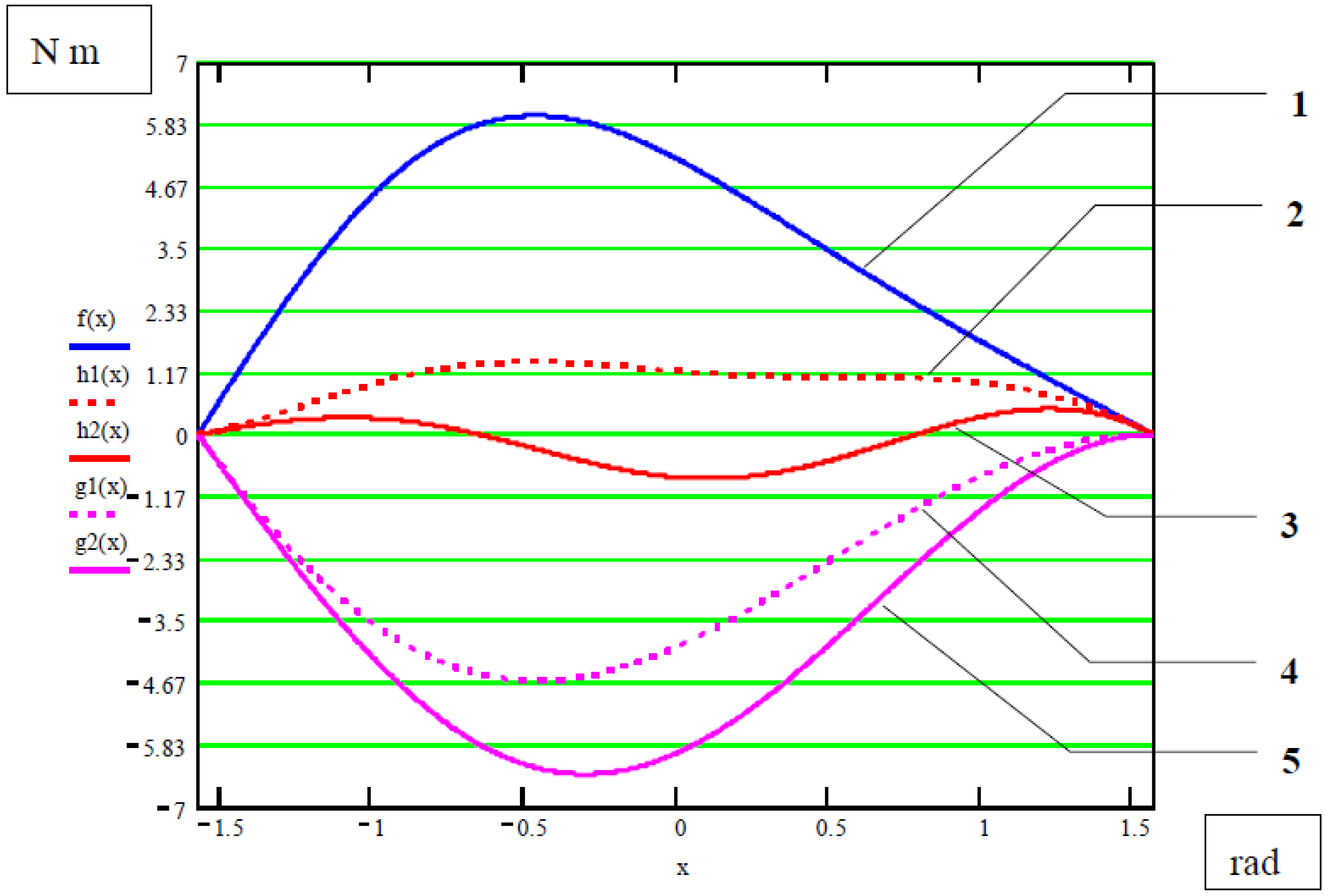
By taking into consideration a parabolic variation of payload as is represented in
Figure 3 (red curve) the maximum unbalancing moment is when the position of balanced arm ① is near the horizontal (
φ = 0.095 [rad]) and has the magnitude of 0.828 Nm (represented by function
h2(
x) plotted in red color in graph from
Figure 9).
The plotted red dashed curve—represented by function
h1(
x) in
Figure 9—show the variation of unbalancing moment in case o linear variation of static load [
30] which has the maximum value about double than in case of parabolic variation (about 1.4 Nm at position
φ = −0.5 rad).
Better balancing obtained in the case of parabolic variation of payload is expressed also by efficaciousness coefficient [
19] with an extended definition in Reference [
30]:
where:
Eb—energy consumed by actuating system of the balanced robot;
Ea—supplementary energy consumed by an additional actuating system in order to obtain active balancing of robot;
Eu—energy consumed by actuating system of the unbalanced robot.
In the case of passive balancing the supplementary energy
Ea is zero and in present example by comparing the other energies without taking into the consideration the frictions the following efficaciousness coefficient are obtained:
More of that the unbalancing moment in the case of parabolic variation of the payload (red solid curve 3 in
Figure 9) has a variation like in
Figure 1b, up and down with respect to the horizontal line of perfect balancing, which is a normal and expected variation in case of approximate balancing [
20].
5. Conclusions
In case of the counterweight balancing two new solutions are proposed in
Figure 4 (both passive) in order to be used in Robotics and Mechatronics fields.
Passive solution from
Figure 4a with a single bar joined between translational counterweight and the ground leads to a surprisingly good balancing with respect to the simplicity of the solution demonstrated by a simulation (
Figure 9). On the other hand the solution is compensating also the variation of the payload (
Figure 3) while the functioning domain is very large from −90° to +90° with respect to horizontal plane. In same conditions the compensation of parabolic variation of payload is better than the compensation in the case of linear variation of payload demonstrated either by simulation results (
Figure 9) and by the efficaciousness coefficient defined in Relation (31). Complementary passive solution with a rocking counterweight (see
Figure 4b) is used in practice for symmetric solution [
10,
11,
12] but never seen for the general case as is proposed in
Figure 4b.
As for the active solutions with counterweight in papers [
30,
31] are proposed two complementary solutions (translating and rocking) that are using as counterweight the actuating motor of the balanced arm and even the mechanical transmission could be used as counterweight if the weight of actuating motor is not enough (as are added in the case of camera stabilizers [
26] the camera battery and the monitor like additional counterweights).
In case of robots it is also possible to remove electric parts from power and control cabinet (like frequency converters for example) and to mount them as counterweights on the mechanical arm. In this case 2 thick cables (with power and with feed-back information) are replaced by only one power cable.
As for the elastic balancing in the case of variable payload four new active solutions with 2 DOF for joints relocation are presented in
Figure 6 and
Figure 7. Mathematical model of a related solution, with only one degree of freedom for relocation by translation of the ground joint of the spring (
Figure 8), is formulated. The advantages of using springs for static balancing are countered in this case of variable payload by the complicated solutions needed for relocation of the spring’s joints.
During the functioning some pressure angles or singularity positions may occur in solutions from
Figure 4 for a certain kinematic dimensions set, which is limiting the static balancing operation and this will be next study together with the solving of an optimum problem as is announced. As for the solutions with springs the limitation is higher due to the real spring itself as is presented in paper [
25]. Starting by this study, additional studies could be made by going to different directions and by taking into account many other subsidiary problems which is closing better to the reality.


