Towards Functional Mobile Microrobotic Systems
by
 , , ,
, , ,
Georges Adam
 ,
,
Sagar Chowdhury
,
Maria Guix
,
Benjamin V. Johnson
,
Chenghao Bi
and
David Cappelleri
* School of Mechanical Engineering, Purdue University, West Lafayette, IN 47907, USA
*
Author to whom correspondence should be addressed.
Robotics 2019, 8(3), 69; https://doi.org/10.3390/robotics8030069
Submission received: 27 June 2019
/
Revised: 26 July 2019
/
Accepted: 1 August 2019
/
Published: 7 August 2019
Abstract
:This paper presents our work over the last decade in developing functional microrobotic systems, which include wireless actuation of microrobots to traverse complex surfaces, addition of sensing capabilities, and independent actuation of swarms of microrobots. We will discuss our work on the design, fabrication, and testing of a number of different mobile microrobots that are able to achieve these goals. These microrobots include the microscale magnetorestrictive asymmetric bimorph microrobot (MAB), our first attempt at magnetic actuation in the microscale; the microscale tumbling microrobot (TUM), our microrobot capable of traversing complex surfaces in both wet and dry conditions; and the micro-force sensing magnetic microrobot (FSMM), which is capable of real-time micro-force sensing feedback to the user as well as intuitive wireless actuation. Additionally, we will present our latest results on using local magnetic field actuation for independent control of multiple microrobots in the same workspace for microassembly tasks.
1. Introduction
With the advent of numerous microfabrication techniques, the prospect for microscale robots has greatly increased over last decade. A fully autonomous fleet of microrobots can potentially revolutionize both in vitro and in vivo cell manipulation/sensing techniques for the biomedical field, assembly operations of heterogeneous microscale objects in the manufacturing field, and targeted drug delivery and biopsy operation in the medical field. Miniaturization of the robot footprint by taking advantage of modern fabrication techniques comes with the challenge of accommodating on-board power, sensing, communication, and control. Often, the robot’s footprint needs to be scaled up in order to accommodate all these accessories, which makes it unsuitable for most of the aforementioned applications.
The challenge is to have a robot small enough to be able to perform these tasks while still having on-board sensors and actuators. Our current research is driven by answering the question: can we out-source all the auxiliary components (e.g., power, sensor, communication and control) to an off-board system and still be able to operate a fully autonomous fleet of wireless mobile microrobots?
Over the years, many microrobot actuation methods have been proposed and studied by researchers. Some of them include: electrostatic [1,2], electro-active using ionic polymer-metal composites [3,4,5,6,7], magnetic [8,9,10,11], electrical-magnetic hybrid [12], opto–thermal [13,14,15], optical [16,17,18], microfluidics [19], bacteria driven [20,21,22,23,24], and chemical [25,26,27] techniques. Of them, magnetic, optical, and microfluidics are non-contact in nature making them suitable for off-board operations. Magnetic actuation has garnered lots of attention in the last decade because of the large range of forces it can provide [28], the ease in ability to make customizable systems [29], cost effectiveness, and its ability to be integrated with many medical instruments, such as magnetic resonance imaging (MRI) machines [30] and ultrasound. One of the greatest limitations to magnetic actuation is the working distance, which reduces the magnetic field strength as a function of distance squared. To overcome this problem, the microrobots can be designed with a higher magnetization, which will make them more responsive to lower magnetic fields. Otherwise, larger currents can be used in the coil systems but this solution has heat and power consumption limitations. Using these solutions in conjunction with a control algorithm that modulates the magnetic field strength based on the location of the microrobots in the workspace will result in smoother actuation.
Typically, robots need to be equipped with sensors/end effectors in order to realize their full potential [31], enhancing their capabilities and functions beyond just locomotion. Our microrobots are fabricated with functional components that are suitable for a particular task, e.g., end-effectors for manipulation, elastic components to indirectly sense force, etc. A fully autonomous functional microrobot must sense the world for feedback. Finely controlled microrobots are applicable to multiple biological applications, such as single-cell manipulation [32,33] and the arrangement of cells in particular configurations in scaffolds for tissue engineering applications [34]. The ability to sense micro-forces accurately and in real-time is desired for the expansion of possible applications of mobile microrobots to areas like intelligent biomanipulation, mechanobiology, and even for advanced theranostics [35]. The most popular means of collecting information from an on-board sensing element is through passive sensing (e.g., with MRI or optical imaging). Optical imaging with an overhead camera is suitable for in vitro applications as well as microassembly operations. However, for in vivo operation, MRI or ultrasound imaging are typically the only available options. The challenge here is to make the functional components within the limited footprint of the robot that are sensitive enough to be operated with passive sensing elements that can be observed by an imaging system.
Generaly, micro-force sensing has been performed based on microelectromechanical systems (MEMS), such as piezoresistive sensors [36,37,38,39], strain gauges [40,41], and capacitive sensors [42,43,44]. These devices are usually extremely delicate and are used in very specific applications. Furthermore, they can be expensive and difficult to integrate into typical experimental test-beds. Similarly, an atomic force microscope (AFM) has been used for micro/nano force sensing [45]. However it suffers from similar problems due to its bulkiness and high cost. Thus, one of our goals is to develop wirelessly controlled microrobots with micro-force sensing capabilities that are versatile, relatively inexpensive, and have a wide range of applications.
Using magnetic actuation, microrobots can be wirelessly and accurately controlled in the workspace. However, the global nature of magnetic actuation is a discouraging factor in designing a fully autonomous fleet of magnetic microrobots that can be controlled individually. Therefore, a major research question is: how can one independently actuate multiple magnetic microrobots?
Our microrobots are designed to be operated in an environment with multiple dynamic obstacles. In a multi-robot operation, each robot is treated as an obstacle with respect to the other and they communicate and synchronize their movements through a centralized system. The planning and control for multiple microrobots becomes challenging since it has to take into account randomly moving obstacles as well as synchronize each individual robot’s path with one another. Furthermore, the planner must be robust to any uncertainty that may arise from sensing and actuation of the system.
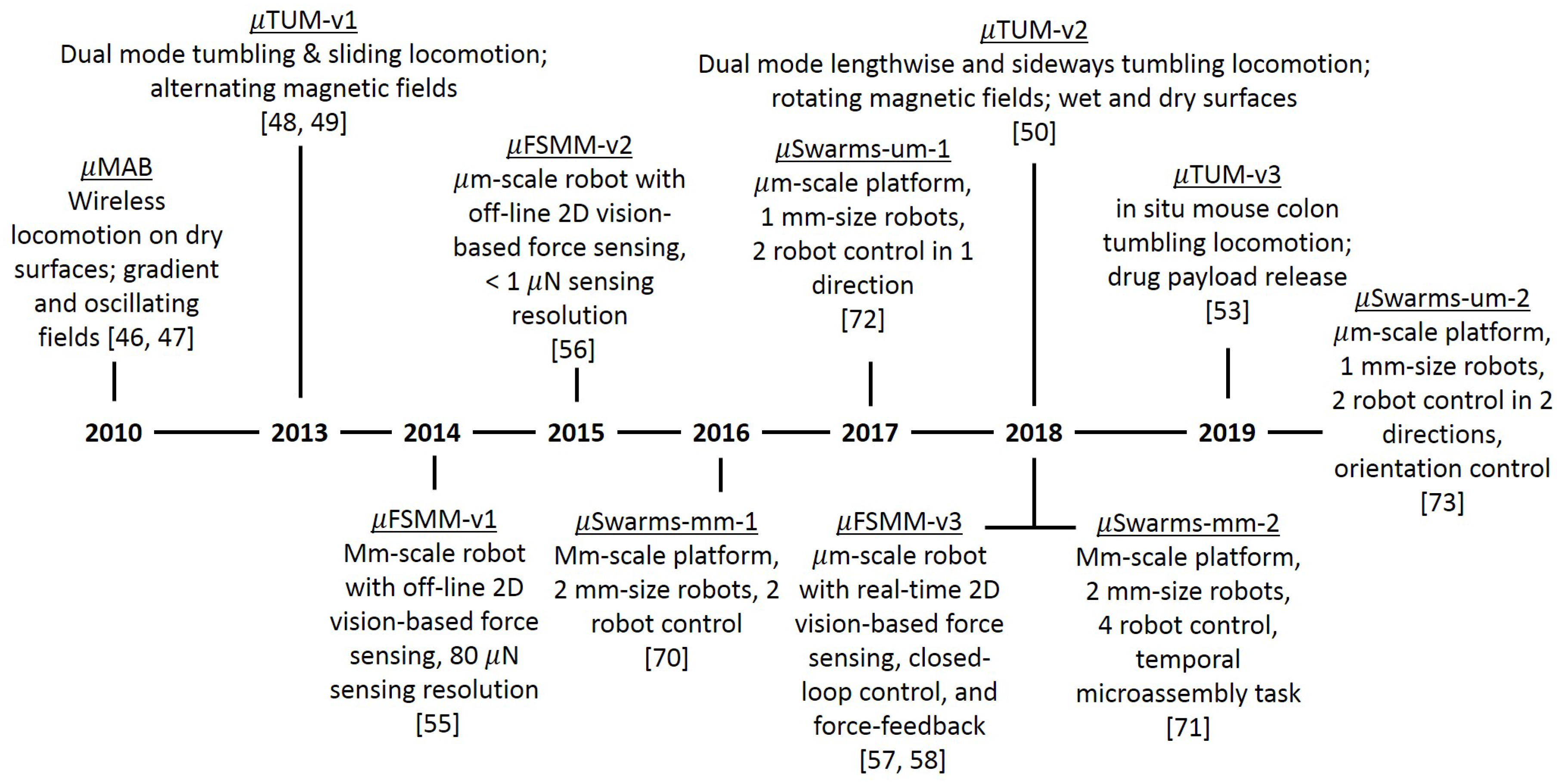
In this paper, we will discuss three microrobot designs in light of the challenges and issues mentioned above. We will also discuss our independent robot swarm platform to address the challenge of planning and control of a multi-microrobot system. The rest of the paper is organized as follows: Section 2 describes the design and fabrication of our first microrobot that tackled the mobility challenges present at the microscale; Section 3 describes our tumbling microrobot, which elevated the mobility capabilities of the previous microrobot and can be used for biomedical applications; Section 4 describes our mobile micro-force sensing microrobot; and Section 5 describes the design and functionality of our local magnetic field system capable of independent control of magnetic microrobots. Figure 1 shows a general progression of the microrobotic work done by our lab over the last decade, including the work discussed in this paper. The following sections will give more details to each of these microrobots and systems. We conclude our paper in Section 6 with a discussion of the importance of the different microrobots we have developed over the years in light of the challenges laid out above.
2. Magnetostrictive Asymmetric Thin Film Bimorph Microrobot (MAB)
Our microrobot exploration started by addressing the mobility challenges present at the microscale. Aiming at the 2010 Mobile Microrobot Challenge, the first microrobot design was a micro-scale magnetostrictive asymmetric thin film bimorph (MAB) microrobot [46,47] (Figure 2). Similar to the piezoelectric effect, a magnetostrictive material generates strain in the presence of an external magnetic field. The MAB design binds a magnetic layer on top of a non-magnetic layer. This bimorph structure will then bend due to the magnetostrictive strain. This way, pulsing a magnetic field on and off will alternately bend and straighten the microrobot body. The deflection of the layered structure was simulated using a piezoelectric finite elements model (FEM) model, translated from magnetostrictive parameters. When the design geometry is asymmetric at both ends, the blocking force due to bending will also be uneven. Therefore, the resulting differential of blocking force from the rear and front ends will translate the microrobot body across the substrate in a step-wise fashion.
The MAB was prototyped using microfabrication techniques in a cleanroom. The non-magnetic layer was made out of SU-8 photoresist (Microchem) that was patterned onto the Silicon wafer using a simple photolithography process, as outlined in the photoresist’s datasheet. Then, the magnetic layer was deposited using a physical vapor deposition (PVD sputtering) method. One of the challenges of this deposition method is the limits on the thickness of the thin film, which can hardly achieve one micron, usually in the nanometer-range. Most magnetic materials present the magnetorestrictive property, however not in a significant manner like a few composite materials, such as Terfenol-D. Unfortunately, Terfenol-D cannot be deposited using the PVD deposition process. Therefore, we used a Nickel layer instead. Given the magnetic layer with suboptimal magnetorestrictive property, the MAB microrobot prototype was actuated on a dry substrate by a pulsating magnetic field. It turned out that only a portion of the trials showed the expected vibrating step-wise motion. It was also observed that the robot translation is significantly influenced by the local substrate condition.
Given these imperfections, our first MAB magnetic microrobot still demonstrated mobility on a dry substrate, which is the critical requirement for the microrobot to work in realistic working environments. The mobility on complex surfaces is still one of the major challenges for microrobots. For this reason, we have investigated another magnetic microrobot design with enhanced mobility capabilities, as detailed in the following section.
3. Micro-Scale Tumbling Magnetic Microrobot (TUM)
3.1. Microrobot Design Overview
Our second mobile magnetic microrobot design was a micro-scale tumbling magnetic microrobot [48,49,50] (TUM). It addressed the mobility challenge on the complex dry substrate with the novel tumbling mechanism. This type of motion was chosen because the pulling force induced from gradient fields is often not strong enough to overcome surface forces between the microrobot and the surfaces they rest on, especially in dry or sticky environments, common to biomedical applications. Drawing inspiration from living organisms and from previous microrobot works, new locomotion forms such as stick-slip motion [51], and oscillating micro-swing hammers [52] were examined. Many of these methods have a point in the motion gait in which the microrobot loses contact with the surface in rough terrain and the motion becomes uncontrollable. Based on that, a dumbbell-shaped microrobot with tumbling locomotion was chosen. The key idea here was to use a different microrobot design and magnetic actuation technique to avoid the significant surface forces that the microrobot can experience. The design along with an alternating or rotating magnetic field is capable of tumbling (rolling) over the complex terrains with large surface forces due to the robots decreased contact area with the surface.
The first generation of TUM was made out of two magnetic ends with opposite polarities and a non-magnetic bridge component joining the two, as shown in Figure 3I-a. In order to achieve the desired tumbling motion, an alternating magnetic field was used. When a vertical magnetic field is applied, one side of the microrobot is repelled from the surface while the other one is attracted. Then, a horizontal field is applied, making it tilt to one side, and then turned off to complete one tumbling cycle, as in Figure 3I-b. Experimental tests have demonstrated reliable locomotion through various surfaces, and unlike the MAB and other microrobots designs working on dry substrates, the TUM uses stiction to its advantage and grips onto the surface.
The design was then improved upon in [50,53], in which a rotating magnetic field is used instead of an alternating field. This change allows the robot’s fabrication procedure to be simplified, where both magnetic portions of the body can be aligned uniformly while keeping the same type of motion. The newer design was shown to be capable of moving predictably in dry environments over multiple complex terrains and even up inclines of up to 45. The magnetic fields were produced using a 8-coil system (MFG-100-i, MagnebotiX AG, Schlieren, Switzerland) capable of producing fields in any direction of up to 20 mT and rotation frequencies of over 20 Hz.
The TUM fabrication procedure consists of photolithography steps using SU-8 photoresist and magnetic particles. First, the SU8-50 photoresist (Microchem) was doped with NdFeB magnetic particles (Magnequench MQFT 5 m, Neo Magnequench) and spin-coated onto a Silicon wafer creating a thin layer. Next, the wafer is exposed to UV light using a mask corresponding to the robot’s geometry in a mask aligner. Lastly, the non-polymerized areas are removed in a bath of SU-8 developer (Microchem Inc., Westborough, MA, USA) and the wafer is then cured in an oven in order to harden the polymer. After the microrobot’s fabrication is completed, the TUM are removed manually from the Silicon wafer using tweezers and a utility knife. Then, the magnetic particles within the SU-8 are aligned in the same direction using a strong magnetic field (9 T), greatly improving the microrobot’s magnetic polarity and response to lower magnetic field strengths.
3.2. TUM Mobility Experiments
Experiments were conducted to assess the mobility of the TUM in complex terrain as well as in different inclines. The incline tests were conducted in both dry and wet conditions and evaluated on a pass/fail basis. The dry air tests received more focus because the lack of buoyancy forces and the significant presence of electrostatic forces makes climbing significantly harder. It was shown [50] that the microrobot is capable of going over a maximum inclination of 45 in dry conditions on paper. In wet conditions, it was shown that the microrobot is capable of climbing inclines of at least 60 in water and silicone oil. The possibility that the robot could be swimming was ruled out after it was observed that the robot did not move forward after losing contact with the surface.
Since the microrobot’s hard magnetic design was achieved using magnetic particles, its magnetic poles can be aligned along any direction, so long as the fabrication procedure permits it. Therefore, two different modes of tumbling modes can be achieved based on the alignment direction: lengthwise tumbling (LT) and sideways tumbling (ST). If the magnetic particles are aligned along the TUM’s major axis, it will perform LT under a rotating magnetic field, whereas when the particles are aligned along the minor axis, ST will occur. Under the same external rotating magnetic field, a LT TUM will travel faster, however it required more force to be raised up from its initial rest position due to the longer moment arm.
Figure 3I-c presents the TUM’s performance over complex terrains, which were 3D printed, and their respective dimensions. Performance over the three 3D printed terrains was similar, and with a slightly lower mean speed. That is due to the fact that these surfaces bump or tilt the robot off to the side during motion, slightly increasing the course of travel. All of the tests were performed with 10 mT field strength at 0.5 Hz. Using the LT motion, the TUM was able to traverse the first three surfaces shown in Figure 3I-c, however it had difficulty getting up from the initial resting position on the honeycomb terrain. After switching to a TUM configured for ST, the honeycomb terrain became much easier to traverse (Figure 3I-c,iv).
3.3. TUM Biomedical Applications
One of the possible biological applications for those robots is targeted drug delivery, using the microrobot as a means to delivering a drug payload to a desired location in the body. In order to test this capability, the diffusion characteristics of a fluorescent payload coating of the microrobot was quantified. The TUM were coated and placed in a phosphate buffered saline (PBS) solution, then monitored over time. Figure 3II-a shows a vial with the microrobot and the diffusion of the fluorescent solution over time. As seen, it is clear that the coating diffuses as desired over time, so in the future, a drug can be used as a payload. This way, the microrobot can be moved to the desired drug delivery location, and the drug will be released once the coating is dissolved.
In order to be used for such biomedical applications as desired, it is imperative that the materials the microrobot is made out are biocompatible. To assess the short-term cytotoxicity of the doped SU-8 used to fabricate the TUM, cells were put in contact with both SU-8 and SU-8 with magnetic particles and studied for a few days. The cell proliferation on these materials was compared to a positive and negative control. Figure 3II-d shows the results of the cytotoxicity tests, and it is shown that both the SU-8 and the SU-8 with magnetic particles allow for the proliferation of cells, which means they are biocompatible.
Next, the locomotion of the TUM was tested in a biological environment (in situ murine colon) and imaged using a high-frequency ultrasound system (Vevo3100, FUJIFILM VisualSonics, Toronto, ON, Canada). Figure 3III shows a time-lapse of the microrobot traversing in a dissected murine colon in a saline solution. For the in-situ tests, the colon was filled with solution and sutured on both ends to ensure the liquid would stay within the colon. The ultrasound images were acquired using B-mode long-axis images of the mid and distal regions [54]. These experiments showed that the microrobot is able to traverse in a murine colon environment and ultrasound is a viable imaging technique for the TUM inside the body.
4. Micro-Force Sensing Mobile Microrobots (FSMM)
4.1. Overview of the Microrobot Design
Further than addressing the mobility challenges in the microscale, we also investigated adding a sensing mechanism to our wireless mobile microrobots. The ability to sense at the microscale is of great importance for the development of new technologies, however sensors at this scale are usually extremely expensive and hard to implement on general systems. The full potential of mobile microrobots can only be realized through the addition of on-board sensing capabilities and closed-loop control. Therefore, we incorporated a vision-based micro-force sensor onto a mobile magnetic microrobot [55,56]. This sensor consists of a compliant structure with measurable stiffness and a vision-based tracking algorithm, which are used in conjunction to measure applied forces. The resulting micro-force sensing mobile microrobot (FSMM) is believed to be the first sub-millimiter scale wireless microrobot with real-time, on-board micro-force sensing capabilities.
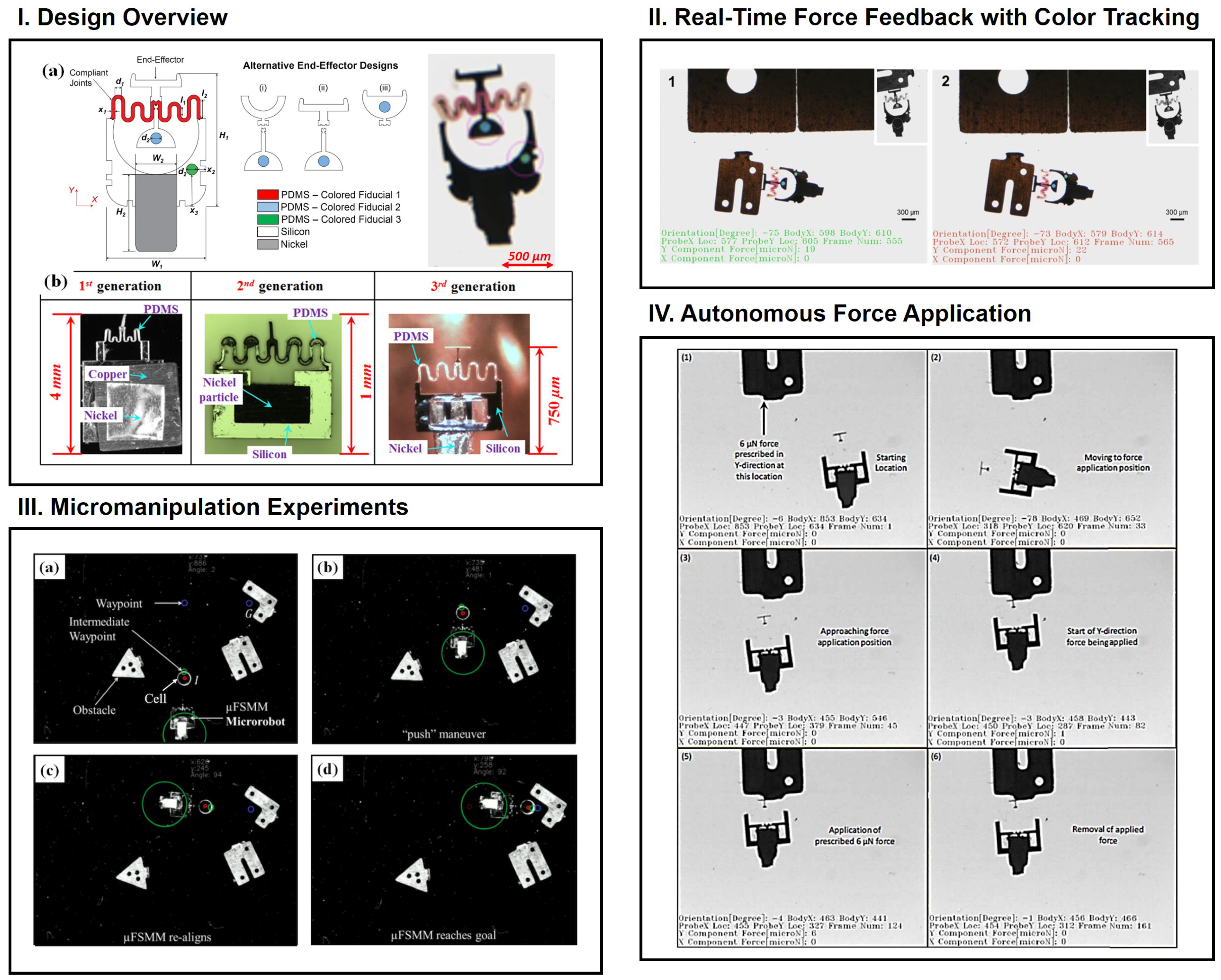
The vision-based force sensor relies on a compliant polydimethylsiloxane (PDMS) spring end-effector with a stiffness low enough that it is capable of applying N-level forces. The compliant structure is attached to the robot’s rigid silicon body and has a specialized rigid end-effector on the opposite end, as shown in Figure 4I-a. Furthermore, a magnetic Nickel body is attached on the back of the FSMM, allowing its motion to be controlled by an external gradient magnetic field. The first generation of FSMM started as a millimiter-scale version, which was then minimized in later generations. The overall footprint from generation 3 and on remained the same, however, the body’s shape was changed and colored fiducials and colored PDMS springs were added in order to achieve faster real-time tracking.
Currently, it is possible to tailor the compliant structure’s stiffness depending on application, to create specialized microrobots for specific tasks. Additionally, application specific end-effectors can be added. In regards to the force-sensing capabilities, the FSMM are able to measure sub-N level forces with a sensing range greater than 100 N. The microrobot is actuated using a gradient magnetic coil system, which allows for position and orientation control. Using control algorithms, the FSMM can be actuated autonomously and provide precise pushing forces at precise locations, as well as perform automated micromanipulation with path planning and obstacle avoidance.
In order to fabricate these microrobots, standard microfabrication techniques are employed. The procedure consists of a series of multiple photolithography steps followed by positive deep reactive ion etching (DRIE) that are repeated until the entire microrobot is completed. The photolithography step patterns the compliant structure on the wafer, and the DRIE creates a trench of the same shape. PDMS, a soft polymer, was poured onto the wafer, creating the desired compliant structures. By adjusting the base/curing agent ratio, it is possible to tune the stiffness of the PDMS structure. The same photolithography process followed by etching was repeated to create the rest of the microrobot, such as the silicon body and colored fiducials (in [57]). At the end of the process a backside etching was used to release the FSMM from the wafer. The nickel (Ni) magnetic body was fabricated separately by a chemical etching process (Fotofab) and then manually glued to the back of the silicon body.
In order to be used as a force sensor, the compliant structures needed to be calibrated and their stiffness measured. The calibrations are conducted using a micro-force sensor (FT-S1000, FemtoTools, Buchs, Switzerland) mounted on a XYZ micromanipulation stage (MP-225, Sutter Instruments, Novato, CA, USA). The stage was moved to specific locations and the forces measured by the sensor are recorded as well as the deflections of the compliant end-effector. Force versus displacement plots were created for both x and y directions, and the stiffness of the microrobot in each direction was extracted using the slopes of these calibration plots.
The FSMM were then ready to be used as a mobile microrobotic micro-force sensor. It is actuated by a gradient magnetic field generated by two pairs of electromagnetic coils arranged symmetrically along a common axis. The microrobots are placed inside a petri dish with a liquid solution (water or silicone oil) within the workspace of the coil system and an overhead camera is used to provide real-time tracking and force sensing.
4.2. Microrobot Capabilities and Applications
Using the magnetic coil system described above and control algorithms based on the overhead camera images, the microrobots gained multiple modes of applications, including autonomous movement with path planning, autonomous micromanipulation and force application, manual micromanipulation with real time force feedback, and even structure stiffness measurement. With path-planning, the user can set desired goal positions for the microrobot or for a structure to be manipulated, and the algorithm will be able to control to FSMM to the goal, while avoiding obstacles and taking the most efficient route. Another possible use is to set a desired position and force for the microrobot to apply, and the microroobt will autonomously traverse to the goal location and apply the desired number of pushes at the set force level. This allows the microrobot to be used for mechanobiology studies investigating how cells develop based on the force applied to its cell membrane [59]. For biomanipulation, both manual and autonomous modes can be used, and force thresholds can be put in place in order to prevent damage to the object being manipulated. Figure 4II shows the manual manipulation of a micropart with real-time force feedback using color tracking. Once the force applied is greater than a set threshold, the screen turns red and the user knows to reduce force. As a result, the user can perform similar micromanipulation tasks while exposing the object being manipulated to minimal forces. Figure 4III shows the autonomous manipulation of a disk (simulating a cell) to a desired goal location while avoiding obstacles. With these capabilities, cells can be arranged in a desired manner, or even sorted by type. Additionally, Figure 4IV shows the autonomous application of a user set force on a desired location. On a measurement note, the FSMM can be used to measure the stiffness of other structures that it interacts with, due to its compliant structure with known stiffness and vision tracking algorithm. This is done by correlating the force applied to the desired object and its deflection observed with the overhead camera. This is particularly useful for diagnosis purposes, whereas cancerous cells are usually stiffer than healthy ones [60].
5. Independently Controllable Microswarms
One of the biggest limitations of magnetic gradient actuation is its global influence on the workspace, which limits the capability to robustly control multiple microrobots in the workspace. Over the years, researchers have investigated different approaches to get around this limitation. Pawashe et al. [61] proposed to use electrostatic anchoring of a microrobot preventing the desired microrobots from moving while another is actuated using the global magnetic field. Another popular approach is to utilize the heterogeneity among different microrobots when actuated by the same global magnetic field. Diller et al. [62] have utilized the non-uniformity of the robots to control them somewhat independently with the global magnetic field in a pushing based manipulation operation. Frutiger et al. [8] developed a microrobot with two non-identical nickel bodies with same magnetization direction. By introducing non-uniformity in the robots, the authors managed to obtain the control of two different robots. DeVon and Bretl [63] have developed a controller for these microbots with carefully introduced heterogeneity that is able to move the robots in different speeds to the desired directions with same global input. However, an inherit coupling of the robot behavior still exists when exploiting homogeneity. Wong et al. [64] came up with an individual magnetic field region for the robots where they can be controlled independently. However, their approach suffers from occasional singularity and faces difficulty in fine control of the robot. Yu et al. [65,66,67] have used electric fields to independently manipulate and control nanowires in fluid suspension. However due to their small size, the actuation force is limited, which poses a barrier to manipulation of micro-objects. Other works showcase the steering and flow control of micro-objects in microfluidic chips [68,69]. The focus in our work is on open environments.
The approaches presented above either suffer from undesired coupling or singularities, which limits their ability to scale up in terms of the number of microrobots individually and independently controlled, as well as greatly limits the manipulation capability of these microrobots. Our research is motivated by alleviating the microrobots from these constraints that emanate from global actuation methods. Instead, we have created a system capable of generating local magnetic fields strong enough to manipulate microrobots in their vicinity but not strong enough to affect the behavior of other robots in the workspace. The system consists of a substrate with an array of planar microcoils, in which we can independently control the current direction and magnitude of each coil. The size of the coils and robots are designed so each coil only actuates a microrobot in its vicinity, creating a magnetic system for independent microrobotic control. Table 1 shows the evolution of our microcoil array platforms in terms of size and manipulation capability. The first generation platform consists of 64 microcoils arranged in a 8 × 8 array. Each coil can generate forces that either push the microrobots towards or away from the center of the coil. Hence, to provide directionality to the actuation, multiple microcoils need to be sequentially activated based on the position of the robot in the workspace. We have developed a heuristic based planning algorithm that not only computes the desired paths for the robots to the respective goal locations but also determines the coils that need to be activated along with the required current and the polarity [70]. We have demonstrated autonomous navigation of two mm-scale robots moving independently towards their respective goal locations by activating a selective number of coils that influence only the motion of the robot in their vicinity (Figure 5I-a).
Using an 11 × 11 version of the millimeter scale platform, more complex experiments were performed, in which up to four robots were actuated independently. Figure 5I-b shows the starting, intermediate, and final positions of the robots, respectively, as well as traces displaying past locations for one particular experiment. Furthermore, the ability of the system to perform an assembly task was demonstrated, as shown in Figure 5I-b. In these experiments, 3D printed end-effectors were fixed to the robots and used to assemble two hexagonal pieces in a specific assembly location. First, robot 1 moved its piece to the assembly location then returned to its initial position, at which time robot 2 moved the final part to the assembly location, thus completing the process.
To reduce the robot size we can independenlty control, we replaced the planar mm-scale microcoil with copper wire strips in the second generation system (m-scale v1 on Table 1). The current direction and magnitude in each micro strip can be controlled independently. We have demonstrated independent actuation of multiple microrobots less than a milimeter in size with this system [70]. However, due to the monolithic arrangement of the microstrips, the actuation force is higher in Y-direction relative to the X-direction and thus the independent movement of the microrobots is limited to the Y-direction. Our heuristic planning algorithm models this disparity in actuation force as action uncertainty and computes paths that have higher actuation force in reaching the goals.
Our most recent platform addresses the disparity in actuation force in X and Y directions by introducing another layer of microstrips on the substrate in an orthogonal direction (m-scale v2 on Table 1) [73]. With the new array of microstrips, it can generate uniform actuation force in both X and Y directions. We use the same planning algorithm to compute the path as well as to determine the current and polarity of the coils to generate desired actuation forces.
For these coil systems, the forces generated in the workspace were not capable of orientation control of the permanent magnetic disk robots, which can make manipulation very limited. The force generated on a robot by a set of microcoils is applied along its centroid, and for a simple disk magnet, the centroid coincides with the center of mass. By offsetting the centroid and the center of mass, the net force on the robot is similar to a force-moment couple acting on the center of mass, as shown in Figure 5II. Therefore, using a specially fabricated robot with a tail to offset its center of mass opposite of a flat manipulation force, the coil system can be used for orientation and position control, greatly increasing the manipulation capabilities of the system. Figure 5III shows the micromanipulation of a part in which orientation control is used in order to change the location and pose of the micro-part [73].
As shown, the developed system allows for the independent control of multiple microrobots in the same workspace, allowing for parallel execution and/or cooperation when executing manipulation tasks. Since the actuation is performed by the microcoils (mm-scale system) or micro strips of wire (m-scale system), the magnetic fields created are small. This necessitates the use of permanent magnetic material in the microrobot designs. The repulsive forces from the permanent magnets limit the separation distance between the microrobots, which ultimately limits the number of microrobots that can work together in the same workspace.
6. Conclusions and Future Outlook
Microrobots with functional components can be used in an extensive variety of tasks at the microscale, ranging from biomanipulation to force sensing to targeted drug delivery. We have demonstrated three different microrobot designs that are capable of navigating in multiple challenging workspaces as well as measuring microforces by interacting with the environment. Actuating these robots with a global magnetic field is a great way of achieving wireless control while keeping the microrobot’s footprint small, however it significantly limits the capabilities to control multiple microrobots independently in the same workspace. To enable this, we have developed a local magnetic field generating system that, along with heuristic based planning algorithms, is able to control multiple microrobots independently. Microrobotic work is incredibly versatile and has tremendous potential future impact in many fields, such as in biology, advanced manufacturing, and medicine.
In regards to the applications demonstrated to date, the primary goal of the MAB was simply locomotion of a wireless, microscale robot. The other microrobots and systems discussed have much more interesting applications. For the TUM, we were able to demonstrate locomotion in complex terrains in both wet and dry conditions. Additionally, it was shown that the microrobot itself is biocompatible and that we are able to coat and diffuse solutions in a medium, showing promise for in-vivo drug delivery applications. Lastly, ultrasound was shown to be a good imaging method and the TUM was able to traverse the inside of a mouse colon. In the case of the FSMMs, we were able to demonstrate real-time micro-force feedback to the user, as well as, autonomous movement with path-planning, autonomous manipulation, and force-controlled application of a desired force at a target location. It has also been able to use it to safely manipulate live cell spheroids in a collagen medium. The microrobot swarm systems presented have been able to demonstrate independent actuation, micromanipulation, and temporal microassembly tasks with the mm-scale system and micromanipulation with orientation control with the micro-scale system.
While many solutions have been discussed, there is still tremendous room for improvement and development of new technologies to realize fully functional mobile microrobotic systems with the capabilities of traditional macro-scale robotics. In the area of microrobotics for in vivo applications, the building blocks are present, as shown by the amount of functionality of the TUM, however there is still the need of an integrated system that will be able to make use of all of the features of such microrobots simultaneously and be able to perform specific tasks in the body. In order to do that, a bio-hybrid design is a possibility, in which biological entities are merged with synthetic microrobots. This will combine the advantages of each. One step along this path is the coating of microrobots with an antibody so only a very specific type of cell or biological entity will attach itself to the microrobots body.
Other hybrid type designs can combine different types of on-board actuation or sensing. Regarding microrobots used for micromanipulation, such as the FSMMs, active actuators can be added to the robot that act independently from the microrobot’s magnetic locomotion, in order to create active end-effectors for various applications. The combination of different types of actuation and sensing methods is imperative for the development of functional microrobots executing complex tasks.
For the independent control of multiple microrobots, the use of magnetic strips of wire, as shown in Section 5, is approaching its limits of minimization and actuation capabilities. This is due to the magnetic interactions between the microrobots, which become more significant the closer the microrobots are to each other. Novel workspace and microbot co-design is crucial for the development of independent control of large numbers of magnetic microrobots using local magnetic fields. With such improvements, microrobots will be able to perform parallel complex tasks with higher efficiency.
Funding
This research was funded by NSF NRI Award #1637961, NSF IIS Award #1358446, and NSF IIS Award #1763689.
Conflicts of Interest
The authors declare no conflict of interest.
References
- Donald, B.; Levey, C.; McGray, C.; Paprotny, I.; Rus, D. An Untethered, Electrostatic, Globally Controllable MEMS Micro-Robot. J. Microelectromech. Syst. 2006, 15, 1–15. [Google Scholar] [CrossRef]
- Contreras, D.S.; Pister, K.S.J.; Sensor, B.; Center, A. Dynamics of Electrostatic Inchworm Motors for Silicon Microrobots. In Proceedings of the 2017 International Conference on Manipulation, Automation and Robotics at Small Scales (MARSS), Montreal, QC, Canada, 17–21 July 2017. [Google Scholar]
- Rodrigues, J.L.; Almeida, R.A.; Dente, J.A.; Branco, P.C. Review of Recent Patents with Applications of Ionic Polymer-Metal Composites (IPMCs). Recent Patents Electr. Electron. Eng. 2011, 4, 10–15. [Google Scholar] [CrossRef]
- Kim, S.J.; Pugal, D.; Wong, J.; Kim, K.J.; Yim, W. A bio-inspired multi degree of freedom actuator based on a novel cylindrical ionic polymer-metal composite material. In Proceedings of the 2011 15th International Conference on Advanced Robotics (ICAR), Tallinn, Estonia, 20–23 June 2011; pp. 435–440. [Google Scholar] [CrossRef]
- Fang, B.K.; Lin, C.C.K.; Ju, M.S. Development of sensing/actuating ionic polymer–metal composite (IPMC) for active guide-wire system. Sens. Actuators A Phys. 2010, 158, 1–9. [Google Scholar] [CrossRef]
- He, Q.; Yang, X.; Wang, Z.; Zhao, J.; Yu, M.; Hu, Z.; Dai, Z. Advanced Electro-active Dry Adhesive Actuated by an Artificial Muscle Constructed from an Ionic Polymer Metal Composite Reinforced with Nitrogen-doped Carbon Nanocages. J. Bionic Eng. 2017, 14, 567–578. [Google Scholar] [CrossRef]
- Aw, K.C.; McDaid, A.J. Bio-applications of ionic polymer metal composite transducers. Smart Mater. Struct. 2014, 23, 074005. [Google Scholar] [CrossRef]
- Frutiger, D.R.; Vollmers, K.; Kratochvil, B.E.; Nelson, B.J. Small, Fast, and Under Control: Wireless Resonant Magnetic Micro-agents. Int. J. Robot. Res. 2010, 29, 613–636. [Google Scholar] [CrossRef]
- Pawashe, C.; Floyd, S.; Sitti, M. Modeling and Experimental Characterization of an Untethered Magnetic Micro-Robot. Int. J. Robot. Res. 2009, 28, 1077–1094. [Google Scholar] [CrossRef]
- Kim, S.; Lee, S.; Lee, J.; Nelson, B.J.; Zhang, L.; Choi, H. Fabrication and Manipulation of Ciliary Microrobots with Non-reciprocal Magnetic Actuation. Sci. Rep. 2016, 6, 30713. [Google Scholar] [CrossRef] [Green Version]
- Dreyfus, R.; Baudry, J.; Roper, M.L.; Fermigier, M.; Stone, H.A.; Bibette, J. Microscopic artificial swimmers. Nature 2005, 862–865. [Google Scholar] [CrossRef]
- Fu, Q.; Guo, S.; Yamauchi, Y.; Hirata, H.; Ishihara, H. A novel hybrid microrobot using rotational magnetic field for medical applications. Biomed. Microdevices 2015, 17, 31. [Google Scholar] [CrossRef]
- Hu, W.; Ishii, K.S.; Fan, Q.; Ohta, A.T. Hydrogel microrobots actuated by optically generated vapour bubbles. Lab Chip 2012, 12, 3821. [Google Scholar] [CrossRef] [PubMed]
- Hu, W.; Fan, Q.; Ohta, A.T. Interactive actuation of multiple opto-thermocapillary flow-addressed bubble microrobots. Robot. Biomim. 2014, 1, 14. [Google Scholar] [CrossRef] [PubMed]
- Hu, W.; Ishii, K.S.; Ohta, A.T. Micro-assembly using optically controlled bubble microrobots. Appl. Phys. Lett. 2011, 99, 094103. [Google Scholar] [CrossRef]
- Thakur, A.; Chowdhury, S.; Švec, P.; Wang, C.; Losert, W.; Gupta, S.K. Indirect pushing based automated micromanipulation of biological cells using optical tweezers. Int. J. Robot. Res. 2014, 33, 1098–1111. [Google Scholar] [CrossRef]
- Banerjee, A.; Chowdhury, S.; Gupta, S.K. Optical Tweezers: Autonomous Robots for the Manipulation of Biological Cells. IEEE Robot. Autom. Mag. 2014, 21, 81–88. [Google Scholar] [CrossRef] [Green Version]
- Glückstad, J.; Villangca, M.J.; Palima, D.Z.; Bañas, A. General rights Light-actuated microrobots for biomedical science. SPIE Newsroom 2017. [Google Scholar] [CrossRef]
- Chowdhury, S.; Svec, P.; Wang, C.; Seale, K.T.; Wikswo, J.P.; Losert, W.; Gupta, S.K. Automated Cell Transport in Optical Tweezers-Assisted Microfluidic Chambers. IEEE Trans. Autom. Sci. Eng. 2013, 10, 980–989. [Google Scholar] [CrossRef]
- Behkam, B.; Sitti, M. Bacterial flagella-based propulsion and on/off motion control of microscale objects. Appl. Phys. Lett. 2007, 90, 023902. [Google Scholar] [CrossRef] [Green Version]
- Steager, E.B.; Sakar, M.S.; Kim, D.H.; Kumar, V.; Pappas, G.J.; Kim, M.J. Electrokinetic and optical control of bacterial microrobots. J. Micromech. Microeng. 2011, 21, 035001. [Google Scholar] [CrossRef]
- Martel, S.; Felfoul, O.; Mathieu, J.B.; Chanu, A.; Tamaz, S.; Mohammadi, M.; Mankiewicz, M.; Tabatabaei, N. MRI-based Medical Nanorobotic Platform for the Control of Magnetic Nanoparticles and Flagellated Bacteria for Target Interventions in Human Capillaries. Int. J. Robot. Res. 2009, 28, 1169–1182. [Google Scholar] [CrossRef]
- Kim, D.H.; Kim, P.S.S.; Julius, A.A.; Kim, M.J. Three-dimensional control of engineered motile cellular microrobots. In Proceedings of the 2012 IEEE International Conference on Robotics and Automation, Saint Paul, MN, USA, 14–18 May 2012; pp. 721–726. [Google Scholar] [CrossRef]
- Martel, S.; Mohammadi, M. Using a swarm of self-propelled natural microrobots in the form of flagellated bacteria to perform complex micro-assembly tasks. In Proceedings of the 2010 IEEE International Conference on Robotics and Automation, Anchorage, AK, USA, 3–7 May 2010; pp. 500–505. [Google Scholar] [CrossRef]
- Chen, C.; Karshalev, E.; Guan, J.; Wang, J. Magnesium-Based Micromotors: Water-Powered Propulsion, Multifunctionality, and Biomedical and Environmental Applications. Small 2018, 14, 1704252. [Google Scholar] [CrossRef] [PubMed]
- Solovev, A.A.; Mei, Y.; Bermúdez Ureña, E.; Huang, G.; Schmidt, O.G. Catalytic Microtubular Jet Engines Self-Propelled by Accumulated Gas Bubbles. Small 2009, 5, 1688–1692. [Google Scholar] [CrossRef] [PubMed]
- Alapan, Y.; Yasa, O.; Yigit, B.; Ceren Yasa, I.; Erkoc, P.; Sitti, M. Microrobotics and Microorganisms: Biohybrid Autonomous Cellular Robots. Annu. Rev. Control Robot. Auton. Syst. 2019, 2, 205–230. [Google Scholar] [CrossRef]
- Abbott, J.; Nagy, Z.; Beyeler, F.; Nelson, B. Robotics in the Small, Part I: Microbotics. IEEE Robot. Autom. Mag. 2007, 14, 92–103. [Google Scholar] [CrossRef]
- Schuerle, S.; Erni, S.; Flink, M.; Kratochvil, B.E.; Nelson, B.J. Three-Dimensional Magnetic Manipulation of Micro-and Nanostructures for Applications in Life Sciences. IEEE Trans. Magn. 2013, 49, 321–330. [Google Scholar] [CrossRef]
- Nacev, A.; Weinberg, I.N.; Mair, L.O.; Hilaman, R.; Algarin, J.; Jafari, S.; Ijanaten, S.; da Silva, C.; Baker-McKee, J.; Chowdhury, S.; et al. Neurostimulation using mechanical motion of magnetic particles wiggled by external oscillating magnetic gradients. In Proceedings of the 2017 8th International IEEE/EMBS Conference on Neural Engineering (NER), Shanghai, China, 25–28 May 2017; pp. 424–427. [Google Scholar] [CrossRef]
- Jing, W.; Chowdhury, S.; Cappelleri, D. Magnetic mobile microrobots for mechanobiology and automated biomanipulation. In Microbiorobotics; Elsevier: Amsterdam, The Netherlands, 2017; pp. 197–219. [Google Scholar]
- Shen, Y.; Fukuda, T. State of the art: Micro-nanorobotic manipulation in single cell analysis. Robot. Biomim. 2014, 1, 21. [Google Scholar] [CrossRef]
- Steager, E.B.; Selman Sakar, M.; Magee, C.; Kennedy, M.; Cowley, A.; Kumar, V. Automated biomanipulation of single cells using magnetic microrobots. Int. J. Robot. Res. 2013, 32, 346–359. [Google Scholar] [CrossRef]
- Tasoglu, S.; Diller, E.; Guven, S.; Sitti, M.; Demirci, U. Untethered micro-robotic coding of three-dimensional material composition. Nat. Commun. 2014, 5, 3124. [Google Scholar] [CrossRef]
- Singh, A.V.; Sitti, M. Targeted Drug Delivery and Imaging Using Mobile Milli/Microrobots: A Promising Future Towards Theranostic Pharmaceutical Design. Curr. Pharm. Des. 2016, 22, 1418–1428. [Google Scholar] [CrossRef]
- Wei, J.; Porta, M.; Tichem, M.; Staufer, U.; Sarro, P.M. Integrated Piezoresistive Force and Position Detection Sensors for Micro-Handling Applications. J. Microelectromech. Syst. 2013, 22, 1310–1326. [Google Scholar] [CrossRef]
- Pfann, W.G.; Thurston, R.N. Semiconducting Stress Transducers Utilizing the Transverse and Shear Piezoresistance Effects. J. Appl. Phys. 1961, 32, 2008–2019. [Google Scholar] [CrossRef]
- Mei, T.; Ge, Y.; Chen, Y.; Ni, L.; Liao, W.H.; Xu, Y.; Li, W.J. Design and fabrication of an integrated three-dimensional tactile sensor for space robotic applications. In Proceedings of the Twelfth Technical Digest. IEEE International MEMS 99 Conference. IEEE International Conference on Micro Electro Mechanical Systems (Cat. No.99CH36291), Orlando, FL, USA, 21 Janurary 1999; pp. 112–117. [Google Scholar] [CrossRef]
- Noda, K.; Hoshino, K.; Matsumoto, K.; Shimoyama, I. A shear stress sensor for tactile sensing with the piezoresistive cantilever standing in elastic material. Sens. Actuators A Phys. 2006, 127, 295–301. [Google Scholar] [CrossRef]
- Hoover, A.M.; Fearing, R.S. Rapidly Prototyped Orthotweezers for Automated Microassembly. In Proceedings of the 2007 IEEE International Conference on Robotics and Automation, Roma, Italy, 10–14 April 2007; pp. 812–819. [Google Scholar] [CrossRef]
- Engel, J.; Chen, J.; Liu, C. Development of polyimide flexible tactile sensor skin. J. Micromech. Microeng. 2003, 13, 359–366. [Google Scholar] [CrossRef] [Green Version]
- Beyeler, F.; Muntwyler, S.; Nelson, B. A Six-Axis MEMS Force–Torque Sensor with Micro-Newton and Nano- Newtonmeter Resolution. J. Microelectromech. Syst. 2009, 18, 433–441. [Google Scholar] [CrossRef]
- Shkel, Y.; Ferrier, N. Electrostriction enhancement of solid-state capacitance sensing. IEEE/ASME Trans. Mechatron. 2003, 8, 318–325. [Google Scholar] [CrossRef]
- Ko, C.T.; Tseng, S.H.; Lu, M.S.C. A CMOS Micromachined Capacitive Tactile Sensor with High-Frequency Output. J. Microelectromech. Syst. 2006, 15, 1708–1714. [Google Scholar] [CrossRef]
- Puchner, E.M.; Gaub, H.E. Force and function: Probing proteins with AFM-based force spectroscopy. Curr. Opin. Struct. Biol. 2009, 19, 605–614. [Google Scholar] [CrossRef] [PubMed]
- Jing, W.; Chen, X.; Lyttle, S.; Fu, Z.; Shi, Y.; Cappelleri, D.J. A Magnetic Thin Film Microrobot with Two Operating Modes. In Proceedings of the IEEE International Conference on Robotics and Automation, Shanghai, China, 9–13 May 2011. [Google Scholar] [CrossRef]
- Jing, W.; Chen, X.; Lyttle, S.; Shi, Y.; Cappelleri, D.J. Design of a Micro-Scale Magnetorestrictive Asymmetric Thin Film Bimorph (μMAB) Microrobot. In ASME International Mechanical Engineering Congress and Exposition; ASME: Vancouver, BC, Canada, 2012; pp. 599–607. [Google Scholar]
- Jing, W.; Pagano, N.; Cappelleri, D.J. A Micro-Scale Magnetic Tumbling Microrobot. In Proceedings of the ASME International Design Engineering Technical Conferences (IDETC), Chicago, IL, USA, 12–15 August 2012. [Google Scholar]
- Jing, W.; Pagano, N.; Cappelleri, D. A Novel Micro-Scale Magnetic Tumbling Microrobot. J. Micro-Bio Robot. 2013, 8, 1–12. [Google Scholar] [CrossRef]
- Bi, C.; Guix, M.; Johnson, B.; Jing, W.; Cappelleri, D.; Bi, C.; Guix, M.; Johnson, B.V.; Jing, W.; Cappelleri, D.J. Design of Microscale Magnetic Tumbling Robots for Locomotion in Multiple Environments and Complex Terrains. Micromachines 2018, 9, 68. [Google Scholar] [CrossRef]
- Floyd, S.; Pawashe, C.; Sitti, M. An untethered magnetically actuated micro-robot capable of motion on arbitrary surfaces. In Proceedings of the 2008 IEEE International Conference on Robotics and Automation, Pasadena, CA, USA, 19–23 May 2008; pp. 419–424. [Google Scholar] [CrossRef]
- Huang, H.W.; Sakar, M.S.; Petruska, A.J.; Pané, S.; Nelson, B.J. Soft micromachines with programmable motility and morphology. Nat. Commun. 2016, 7, 12263. [Google Scholar] [CrossRef] [Green Version]
- Bi, C.; Niedert, E.E.; Adam, G.; Lambert, E.; Solorio, L.; Goergen, C.J.; Cappelleri, D.J. Tumbling Magnetic Microrobots for Biomedical Applications. In Proceedings of the International Conference on Manipulation, Automation and Robotics at Small Scales (MARSS), Helsinki, Finland, 1–5 July 2019. [Google Scholar]
- Freeling, J.L.; Rezvani, K. Assessment of murine colorectal cancer by micro-ultrasound using three dimensional reconstruction and non-linear contrast imaging. Mol. Ther. Methods Clin. Dev. 2016, 5, 16070. [Google Scholar] [CrossRef]
- Jing, W.; Cappelleri, D. A Magnetic Microrobot with In-Situ Force Sensing Capabilities. Robotics 2014, 3, 106–119. [Google Scholar] [CrossRef]
- Jing, W.; Cappelleri, D. Micro-Force Sensing Mobile Microrobots. In Proceedings of the SPIE, Baltimore, MD, USA, 22 April 2015. [Google Scholar]
- Guix, M.; Wang, J.; An, Z.; Adam, G.; Cappelleri, D.J. Real-Time Force-Feedback Micromanipulation Using Mobile Microrobots With Colored Fiducials. IEEE Robot. Autom. Lett. 2018, 3, 3591–3597. [Google Scholar] [CrossRef]
- Jing, W.; Chowdhury, S.; Guix, M.; Wang, J.; An, Z.; Johnson, B.V.; Cappelleri, D.J. A Microforce-Sensing Mobile Microrobot for Automated Micromanipulation Tasks. IEEE Trans. Autom. Sci. Eng. 2018, 1–13. [Google Scholar] [CrossRef]
- Hersen, P.; Ladoux, B. Push it, pull it. Nature 2011, 470, 340–341. [Google Scholar] [CrossRef]
- Yue, X.; Nguyen, T.D.; Zellmer, V.; Zhang, S.; Zorlutuna, P. Stromal cell-laden 3D hydrogel microwell arrays as tumor microenvironment model for studying stiffness dependent stromal cell-cancer interactions. Biomaterials 2018, 170, 37–48. [Google Scholar] [CrossRef]
- Pawashe, C.; Diller, E.; Floyd, S.; Sitti, M. Assembly and disassembly of magnetic mobile micro-robots towards deterministic 2-D reconfigurable micro-systems. In Proceedings of the 2011 IEEE International Conference on Robotics and Automation, Shanghai, China, 9–13 May 2011; pp. 261–266. [Google Scholar] [CrossRef]
- Diller, E.; Floyd, S.; Pawashe, C.; Sitti, M. Control of Multiple Heterogeneous Magnetic Microrobots in Two Dimensions on Nonspecialized Surfaces. IEEE Trans. Robot. 2012, 28, 172–182. [Google Scholar] [CrossRef]
- DeVon, D.; Bretl, T. Control of many robots moving in the same direction with different speeds: A decoupling approach. In Proceedings of the 2009 American Control Conference, St. Louis, MO, USA, 10–12 June 2009; pp. 1794–1799. [Google Scholar] [CrossRef]
- Wong, D.; Wang, J.; Steager, E.; Kumar, V. Control of Multiple Magnetic Micro Robots. In Proceedings of the Volume 4: 20th Design for Manufacturing and the Life Cycle Conference; 9th International Conference on Micro-and Nanosystems, Boston, MA, USA, 2–5 August 2015; p. V004T09A041. [Google Scholar] [CrossRef]
- Yu, K.; Yi, J.; Shan, J. Motion Control, Planning and Manipulation of Nanowires Under Electric-Fields in Fluid Suspension. IEEE Trans. Autom. Sci. Eng. 2015, 12, 37–49. [Google Scholar] [CrossRef]
- Yu, K.; Yi, J.; Shan, J. Simultaneous Multiple-Nanowire Motion Control, Planning, and Manipulation Under Electric Fields in Fluid Suspension. IEEE Trans. Autom. Sci. Eng. 2018, 15, 80–91. [Google Scholar] [CrossRef]
- Yu, K.; Yi, J.; Shan, J.W. Real-time motion planning of multiple nanowires in fluid suspension under electric-field actuation. Int. J. Intell. Robot. Appl. 2018, 2, 383–399. [Google Scholar] [CrossRef]
- Probst, R.; Cummins, Z.; Ropp, C.; Waks, E.; Shapiro, B. Flow Control of Small Objects on Chip: Manipulating Live Cells, Quantum Dots, and Nanowires. IEEE Control Syst. 2012, 32, 26–53. [Google Scholar] [CrossRef]
- Chaudhary, S.; Shapiro, B. Arbitrary steering of multiple particles independently in an electro-osmotically driven microfluidic system. IEEE Trans. Control Syst. Technol. 2006, 14, 669–680. [Google Scholar] [CrossRef] [Green Version]
- Chowdhury, S.; Jing, W.; Cappelleri, D.J. Towards Independent Control of Multiple Magnetic Mobile Microrobots. Micromachines 2016, 7, 3. [Google Scholar] [CrossRef]
- Kantaros, Y.; Johnson, B.V.; Chowdhury, S.; Cappelleri, D.J.; Zavlanos, M.M. Control of Magnetic Microrobot Teams for Temporal Micromanipulation Tasks. IEEE Trans. Robot. 2018, 34, 1472–1489. [Google Scholar] [CrossRef] [Green Version]
- Chowdhury, S.; Johnson, B.V.; Jing, W.; Cappelleri, D.J. Designing local magnetic fields and path planning for independent actuation of multiple mobile microrobots. J. Micro-Bio Robot. 2017, 12, 21–31. [Google Scholar] [CrossRef]
- Johnson, B.V.; Cappelleri, D.J. Microrobot Design for Micromanipulation with Orientation Control Using Local Magnetic Fields. In Proceedings of the International Conference on Manipulation, Automation and Robotics at Small Scales (MARSS), Helsinki, Finland, 1–5 July 2019. [Google Scholar]
Figure 1.
Summary of the progress creating functional mobile microrobotic systems.

Figure 2.
(a) Micro-scale magnetostrictive asymmetric thin film Bimorph (MAB) microrobot and (b) the magnetic field system used to actuate these microrobots. (Images reproduced with permission from [46,47]).

Figure 3.
I. (a) Design schematic of the first generation of microscale tumbling microrobot (TUM) and a prototype is a U.S. dime, (b) the tumbling locomotion mechanism and snapshots of one tumbling cycle, and (c) the locomotion of a newer generation TUM over complex surfaces and a time lapse of its motion in a flat aluminum sheet. II. (a) Cumulative mass drug release percentage (for the first 24 h), (b) microrobot initially placed in vial, and (c) microrobot in vial with phosphate buffered saline (PBS) after 24 h. Green solution is the fluorescent material released from poly(lactic-co-glycolic acid) (PLGA) coating. (d) Fluorescent images taken of cell proliferation for four different test cases (environments). Green fluorescent cells indicate living cells that have adhered to the well plate and are visible. III. Setup for ultrasound imaging, with ultrasound probe (a), petri dish with sample (b), permanent magnet for actuation (c), and motor to create a rotating magnetic field (d). Time lapse over a three second time period of TUM traversing inside a murine colon during the dissected in situ experiment (e). The microrobot is traversing at roughly 1.9 mm/s. (Images reproduced with permission from [49,50,53] (II-III © 2019 IEEE)).

Figure 4.
I. Design overview: (a) schematic and image of the most recent micro-force sensing magnetic microrobot (FSMM) design (with colored fiducials for tracking), and (b) evolution of the microrobot’s design, showing the significant miniaturization of the footprint. II. Real-time force feedback with color tracking: experiments demonstrating real-time force feedback to the user while pushing a micro-block. III. Micromanipulation experiments: automated manipulation of cell with real-time force sensing using the FSMM (a–d) showing automatic re-alignment (c). IV. Autonomous force application: automated pushing with a prescribed force at a desired location. (Images reproduced with permission from [57,58]).

Figure 5.
I. mm-Scale experiments: (a) Demonstration of independent autonomous navigation of two robots with the mm scale 8 × 8 coil array [70], and (b) independent control of four robots (R1, R2, R3, and R4) in which they move clockwise towards the starting position of the next robot. (c) Two-robot assembly task, in which each robot is fitted with a 3D printed end-effector and moves a part to the assembly location. II. -Scale orientation overview: (a) robot used for orientation control, with drive magnet and aligned tail cube magnet opposite to the manipulation side of the robot; (b) equivalent force-moment couple for force shown in (a); (c) sample path of a robot showing the changes in orientation. III. -Scale orientation control experiments: micromanipulation of a part using orientation control to change its final position and pose (a–h). (Images reproduced with permission from: [71,73] (II-III © 2019 IEEE)).


Table 1.
Evolution of local magnetic field generating system.
| Microcoil Platform | |||
|---|---|---|---|
| mm scale | m scale v1 | m scale v2 | |
| Workspace |  |  |  |
| References | [70,71] | [72] | [73] |
| Coil type | Spiral (5 Turns) | Straight wire | Straight wire |
| Number of coil layers | 1 | 1 | 2 |
| Number of coils | in each coil layer) | ||
| Coil dimensions | |||
| Coil spacing | |||
| Workspace dimensions | |||
| Robot footprint | ≥ | ≥ | ≥ |
| Movement type | Discrete | Continuous | Continuous |
| Direction Control | Center and Diagonal | Y Only | Any in XY Plane |
© 2019 by the authors. Licensee MDPI, Basel, Switzerland. This article is an open access article distributed under the terms and conditions of the Creative Commons Attribution (CC BY) license (http://creativecommons.org/licenses/by/4.0/).
Share and Cite
MDPI and ACS Style
Adam, G.; Chowdhury, S.; Guix, M.; Johnson, B.V.; Bi, C.; Cappelleri, D. Towards Functional Mobile Microrobotic Systems. Robotics 2019, 8, 69. https://doi.org/10.3390/robotics8030069
AMA Style
Adam G, Chowdhury S, Guix M, Johnson BV, Bi C, Cappelleri D. Towards Functional Mobile Microrobotic Systems. Robotics. 2019; 8(3):69. https://doi.org/10.3390/robotics8030069
Chicago/Turabian StyleAdam, Georges, Sagar Chowdhury, Maria Guix, Benjamin V. Johnson, Chenghao Bi, and David Cappelleri. 2019. "Towards Functional Mobile Microrobotic Systems" Robotics 8, no. 3: 69. https://doi.org/10.3390/robotics8030069
Note that from the first issue of 2016, this journal uses article numbers instead of page numbers. See further details here.