Collection and Analysis of Human Upper Limbs Motion Features for Collaborative Robotic Applications
by
 , , and
Elisa Digo
1,* ,
,
Mattia Antonelli
1,
Valerio Cornagliotto
1,
Stefano Pastorelli
1 and
Laura Gastaldi
2 1
Department of Mechanical and Aerospace Engineering, Politecnico di Torino, 10129 Turin, Italy
2
Department of Mathematical Sciences “G.L. Lagrange”, Politecnico di Torino, 10129 Turin, Italy
*
Author to whom correspondence should be addressed.
Robotics 2020, 9(2), 33; https://doi.org/10.3390/robotics9020033
Submission received: 27 March 2020
/
Revised: 7 May 2020
/
Accepted: 8 May 2020
/
Published: 11 May 2020
Abstract
:(1) Background: The technologies of Industry 4.0 are increasingly promoting an operation of human motion prediction for improvement of the collaboration between workers and robots. The purposes of this study were to fuse the spatial and inertial data of human upper limbs for typical industrial pick and place movements and to analyze the collected features from the future perspective of collaborative robotic applications and human motion prediction algorithms. (2) Methods: Inertial Measurement Units and a stereophotogrammetric system were adopted to track the upper body motion of 10 healthy young subjects performing pick and place operations at three different heights. From the obtained database, 10 features were selected and used to distinguish among pick and place gestures at different heights. Classification performances were evaluated by estimating confusion matrices and F1-scores. (3) Results: Values on matrices diagonals were definitely greater than those in other positions. Furthermore, F1-scores were very high in most cases. (4) Conclusions: Upper arm longitudinal acceleration and markers coordinates of wrists and elbows could be considered representative features of pick and place gestures at different heights, and they are consequently suitable for the definition of a human motion prediction algorithm to be adopted in effective collaborative robotics industrial applications.
1. Introduction
An important innovation following on the technological developments of Industry 4.0 is the introduction of robots in support of workers’ activities. Collaborative frameworks are positively influenced by the combination of human flexibility, perception, and intelligence with robots’ repeatability and precision [1]. The team formed by humans and robots takes advantage of complementary skills in order to reach a common goal with a safe, successful, and efficient execution [2,3,4]. However, in the absence of a human prediction operation, collaboration cannot be considered optimal. In fact, the ability of the robot to predict human activity by identifying actions, timing, and paths results in a safer and more efficient interaction [5,6].
Several literature works have already investigated the concept of human activity prediction based on motion tracking. In order to perform this prediction operation, human motion data have been collected with different motion capture instruments such as stereophotogrammetric systems [7,8] and RGB-D cameras [9,10]. Some studies have used human motion data to plan a collision-free trajectory for the robot in an industrial environment [9,11] or in a service robotics context [12]. Other works have adopted human motion prediction to improve the performance of the robotic system, reducing the task execution time while maintaining safety standards [13,14]. Furthermore, some studies have trained and tested their prediction algorithm on existing databases of human motions [15,16]. Literature databases containing human motion information are mainly composed of 3D coordinates of joints acquired with optical and stereophotogrammetric systems during total body movements [17,18,19,20]. Some databases also contain inertial data acquired with Inertial Measurement Units (IMUs), but these have some shortcomings. For instance, IMUs have been placed on wrists, ankles, and hips without providing a complete tracking of upper limbs motions [21]. Similarly, in [22], the upper body was not tracked in a complete way, since only two inertial sensors were fixed on the arms, and moreover, typical gestures of industrial context were not analyzed. No literature database has been found with both joints’ 3D coordinates and complete inertial data related to upper body movements common in manufacturing. Some previous literature works have already investigated pick and place gestures by studying the effects of cycle time on physical demands [23] and the effects of object horizontal locations on shoulder kinematics [24]. However, these studies are more focused on ergonomic aspects rather than on the analysis of biomechanical features for the development of a prediction algorithm. To the authors’ knowledge, no previous study analyzes upper body motion features during pick and place gestures at different heights. Finally, most literature works implementing a human motion prediction algorithm have focused more on the explanation of the adopted prediction approach rather than on features’ analysis and selection [9,16,25]. Indeed, these works have given human motion variables as input to different prediction approaches, such as neural networks or probabilistic models, and they have only evaluated the results. However, they have not provided any details about the relevance of each feature or recorded signal.
For all these reasons, the purpose of the present study was twofold: (1) to create a collection of human upper limbs spatial and inertial variables of typical industrial gestures; and (2) to analyze the most representative motion features of pick and place gestures at different heights from the future perspective of effective collaborative robotic applications and human motion prediction algorithms based on sensor fusion. More in detail, 10 healthy young subjects were asked to perform a sequence of 15 pick and place acts at three different heights. The gestures, performed in laboratory tests, were in line with those proposed in other previous works oriented to an industrial concept of assembly in collaboration with a robot [7,10,11]. Inertial Measurement Units and a stereophotogrammetric system were adopted to track participants’ upper body motion and to create a database. Ten collected features of this database were selected and used to distinguish among the three different heights of the picked and placed objects. From the comparison between gestures sequences performed by subjects and gestures sequences recognized from features trends, confusion matrices were built, and F1-scores were calculated. Starting from this performance evaluation, the most representative features were identified as suitable input for an algorithm to predict human gestures in industrial tasks, based on sensor fusion.
Taking advantage of an early recognition and detection of the worker’s gestures, robot motion controls could plan around them. In a collaborative human-centric environment, robot trajectories could be optimized to improve synergy and reduce task execution times, guaranteeing collision avoidance and worker safety concurrently.
2. Materials and Methods
2.1. Participants
Ten healthy young subjects (6 males and 4 females) with no declared musculoskeletal or neurological disease participated in the experiment after giving their written informed consent. All involved subjects were right-handed.
2.2. Instruments
The instrumentation adopted for the study involved two motion capture systems: an inertial one composed of 7 IMUs and a stereophotogrammetric one with 3 cameras and 17 markers.
2.2.1. IMUs
Seven MTx IMUs (Xsens, Enschede, The Netherlands) were used for the test. Each of them contained a tri-axial accelerometer, gyroscope, and magnetometer. Accelerometer and gyroscope measurement ranges were set respectively to ±5 g and ±1200 dps. The first IMU (TAB) was fixed along a table edge in order to refer all IMUs to the reference system of this sensor (Figure 1a). Another 6 IMUs were fixed on the upper bodies of participants according to the following configuration (Figure 1b,c):
- Right forearm (RFA)
- Right upper arm (RUA)
- Shoulders (RSH, LSH)
- Sternum (THX)
- Pelvis (PLV)
A chain of IMUs was created by connecting them through cables. The PLV-IMU was also connected to the Xbus Master; the control unit was able to send synchronous, sampled, and digital data to PC via Bluetooth. Data were acquired through the Xsens proprietary software MT Manager at 50 Hz.
2.2.2. Stereophotogrammetric System
The stereophotogrammetric system adopted for the test was composed of a V120:Trio tracking bar (OptiTrack, Corvallis OR, USA) and 17 passive reflective markers with a diameter of 14 mm. The bar was self-contained, pre-calibrated, and equipped with three cameras that are able to detect infrared light. Three markers (A, B, and C) were fixed on the table in order to define a global reference system aligned with table edges: the x-axis was obtained considering markers A and B; a support s-axis was obtained considering markers C and B; the z-axis was estimated as a cross-product of the x and s axes; as a consequence, the y-axis was calculated as a cross-product of the z and x axes (Figure 1a). Another 14 markers were positioned on participants’ upper body according to the following configuration (Figure 1b,c):
- styloid processes (WMR, WLR, WML, WLL)
- elbow condyles (EMR, ELR, EML, ELL)
- acromions (ACR, ACL)
- between suprasternal notches (IJ)
- the spinal process of the 8th thoracic vertebra (T8)
- on RFA-IMU (SFA)
- on RUA-IMU (SUA)
The stereophotogrammetric tracking bar was placed in front of the table and connected to a PC. Data acquisition was made through the software Motive with a sampling frequency of 120 Hz.
2.3. Protocol
The test was conducted in a laboratory, where one participant at time was seated at the table. Three colored boxes of the same size were placed on the right hand side of the subject at different heights: a white box on the table, a black one 18 cm from the table, and a red one 28 cm from the table (Figure 2a,b). A silhouette of right and left hands with thumbs 32 cm apart was drawn on the table in front of participants, in order to standardize the neutral position to be taken at the beginning and during the exercise (Figure 2a,b). In addition, a cross was marked on the table between the hands’ silhouettes, in order to indicate to the participants where to place the box on the table.
Subjects were first asked to hit their right wrist on the table, in order to temporally synchronize the two motion capture systems. Then, they were asked to stand still for 10 s in the neutral position, with hands leaning on the silhouette for initial calibration. Subsequently, participants performed with the right arm the pick and place task composed of the following 7 steps (Figure 3):
- Start with hands in neutral position
- Pick the box according to the color specified by the experimenter
- Place the box correspondingly to the cross marked on the table
- Return with hands in neutral position
- Pick the same box
- Replace the box in its initial position
- Return with hands in neutral position
In order to ensure that each step was performed by all subjects at the same pace, a metronome, set to 45 bpm, was used. Participants were asked to match each step of the pick and place task with a beat of the metronome. Two experimenters visually checked that the pace was followed by the participants, possibly asking the subjects to repeat the test if it was not performed correctly.
Each subject performed 15 consecutive gestures of pick and place, 5 for every box. The sequence of boxes to be picked and placed was randomized and voice-scanned by the experimenter during the test. In Figure 2c, the random sequence of the boxes is reported. Each row represents all 15 random gestures (5 for every box) performed by each subject. The gestures sequence is indicated with the same color code of boxes.
2.4. Signal Processing and Data Analysis
Signal processing and data analysis were conducted with Matlab® routines. Temporal synchronization of instruments was achieved by considering the right wrist hit on the table. The zero instant was selected as the frame corresponding to both the maximum peak of RFA-IMU acceleration norm and the minimum peak of SFA-marker vertical trajectory [27]. Then, markers coordinates were resampled at 50 Hz in order to be easily compared with the IMUs output and these were expressed with respect to the global reference system [28].
The robotic multibody approach was applied, by modeling the upper body of participants in rigid links connected by joints [29,30]. In detail, five body segments were identified: the right forearm, left forearm, right upper arm, left upper arm, and trunk. Subsequently, starting from the markers positions, a local anatomical reference system was built for each of the three segments involved in the motion: the right forearm, right upper arm, and trunk (Figure 4). The right forearm and right upper arm systems, (xfa, yfa, zfa) and (xua, yua, zua) respectively, were constructed in the same way: x-axes (xfa, xua) were longitudinal to the segments; z-axes (zfa, zua) were perpendicular to the planes defined by x-axes and support s-axes (sfa, sua); y-axes (yfa, yua) were obtained to complete right-handed frames. The right forearm system was centered in the middle point between the WMR and WLR markers, whereas the right upper arm system center was identified as the middle point between the EMR and ELR markers. Furthermore, the x-axis of the right upper arm system was defined through the shoulder center, which was obtained by subtracting in a vertical direction from the ACR marker the 17% of acromions distance [31]. The trunk anatomical reference system was centered in the middle point between ACR and ACL markers, and it was composed of a vertical x-axis (xtr), a horizontal y-axis (ytr), and a z-axis (ztr) to complete a right-handed frame. Moreover, since WLR and EMR markers could be affected by occlusion during the movement, also technical reference systems (xtfa, ytfa, ztfa) and (xtua, ytua, ztua) were built for right forearm and right upper arm segments respectively, exploiting support s-axes (stfa, stua). These systems were defined by involving other markers: ELR and SFA for the forearms and ACR and SUA for the upper arms (Figure 4). Technical systems were used when necessary to reconstruct the trajectory of occluded markers. In fact, the constant transformation between an occluded marker and the corresponding technical system was identified during the initial calibration when the subject was in a neutral position.
Since IMUs axes were not aligned with anatomical axes, also IMUs data had to be referred to anatomical systems defined with markers. In order to fulfill this purpose, the transformation between IMUs’ local reference frames and markers’ anatomical systems was identified with the neutral position of subjects and then considered constant during the movement. Moreover, IMU signals were filtered with a second-order Butterworth low-pass filter with a cut-off frequency of 2 Hz.
Finally, from the observation of variables in the database, 10 features were selected because of their less noisy and more significant trend. More in detail, 8 features from markers coordinates expressed in the table system and 2 features of IMUs signals referred to anatomical axes were considered:
- X-coordinate of the marker on the right wrist medial styloid process (WMR)
- Y-coordinate of the marker on the right wrist medial styloid process (WMR)
- X-coordinate of the marker on the right wrist lateral styloid process (WLR)
- Y-coordinate of the marker on the right wrist lateral styloid process (WLR)
- X-coordinate of the marker on the forearm sensor (SFA)
- Z-coordinate of the marker on the upper arm sensor (SUA)
- Z-coordinate of the marker on the right elbow medial condyle (EMR)
- Z-coordinate of the marker on the right elbow lateral condyle (ELR)
- X-acceleration of the IMU on the right upper arm (RUA)
- Z-acceleration of the IMU on the right upper arm (RUA)
In each recorded feature, a double peak identified a pick and place gesture of a box. As example, Figure 5 depicts the feature z-coordinate of ELR for subject number 5. The signal showed 15 pairs of peaks corresponding to 15 gestures performed by each participant. A custom Matlab code was used to identify all peaks. The amplitude of each pair of consecutive peaks was averaged, and the mean values pi (i = 1 ÷ 15) were evaluated. Then, the mean value m and the standard deviation σ of pi values were calculated. A band centered on m and with a peak-to-peak amplitude σ was defined. Subsequently, an algorithm for the distinction of the three sets of pick and place gestures was implemented by considering the position of each pi value with respect to the band. The algorithm was defined according to the following logical statements:
if pi < (m − σ/2), then pi = pick of lower box (white)
if (m − σ/2) ≤ pi ≤ (m + σ/2), then pi = pick of middle box (black)
if pi > (m + σ/2), then pi = pick of higher box (red)
The mean value and the amplitude of the band were defined according to each participant’s acquired data, in order to customize the recognition procedure in each sequence. The algorithm results about the distinction among the pick and place of the three boxes, corresponding to the different heights, are displayed in Figure 5. Gestures are classified as low, medium, and high. The same algorithm was applied for all selected features.
Afterwards, starting from the comparison between the real sequence of gestures performed by participants and the sequence of gestures identified by the algorithm, a confusion matrix was built for each feature. Finally, confusion matrices were adopted to estimate F1-scores, which are performance indices of an experiment’s results [32]. In this case, F1-scores evaluated the algorithm capacity to discriminate the gesture as low, medium, or high by combining precision and recall values as reported by [32]. F1-scores were calculated for each considered feature and for each of the three heights.
3. Results
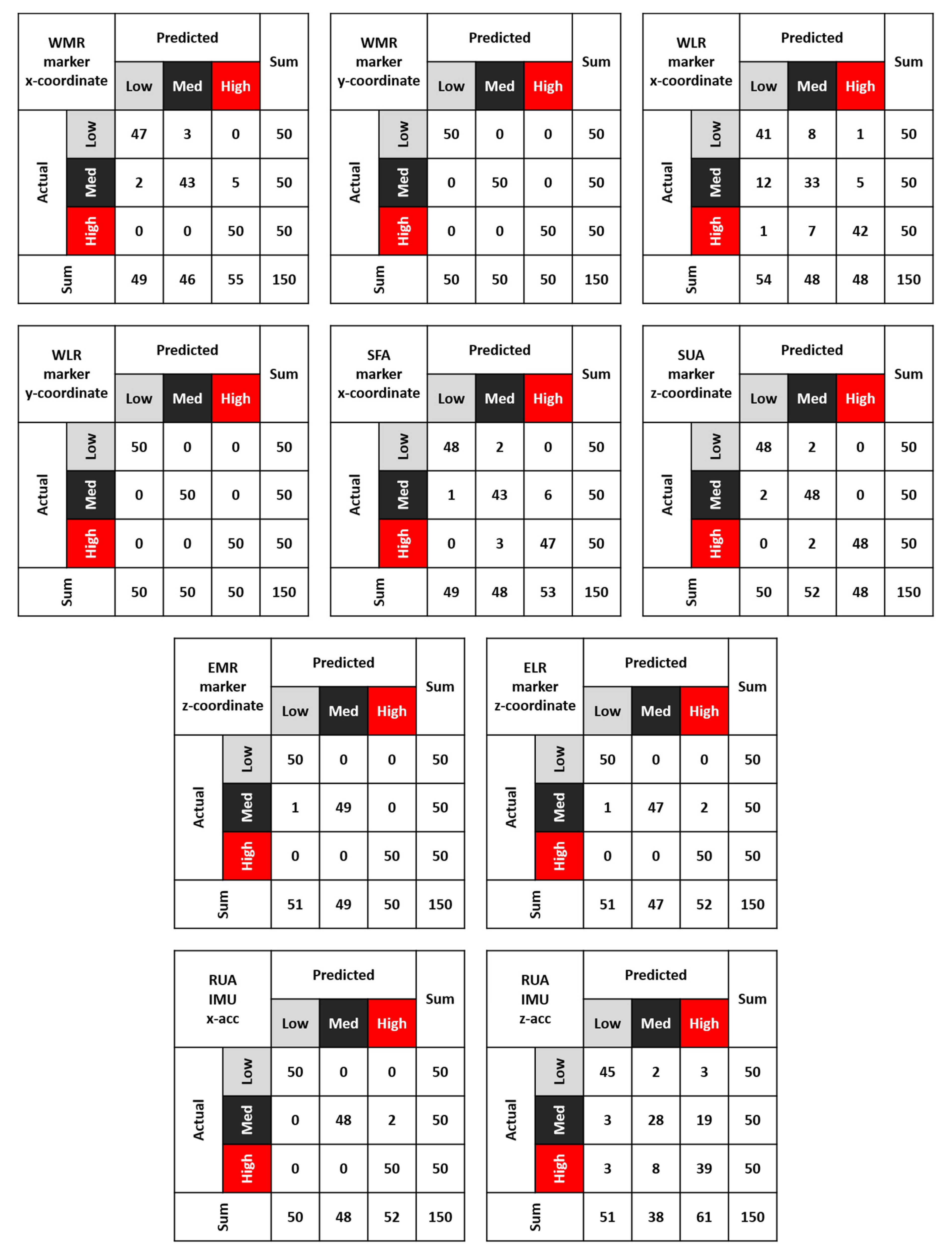
Figure 6 shows 10 4-by-4 confusion matrices, one for each selected feature of the database. Excluding the last row and the last column of each matrix, the remaining 3-by-3 matrix contains the actual number of gestures on rows and the predicted numbers on columns. The first three elements of the fourth row contain the sums of predicted numbers of each category, whereas the first three elements of the fourth column contain the sums of real numbers of the three movements. The last element of the matrix is always equal to 150, which is the total number of gestures collected in the database. Moreover, the matrix diagonal contains numbers of the correctly classified gestures for each of the three classes. Table 2 shows F1-scores (%) estimated for every movement by applying the algorithm on each feature. The first column contains the list of 10 features selected from the database, whereas the other three columns show the percentage F1-scores for low, medium, and high gestures, respectively.
4. Discussion
The first aim of this study was to create a collection of human upper limbs variables recorded by both IMUs and a stereophotogrammetric system during typical industrial movements of pick and place. Other literature databases of human motion variables have some shortcomings with respect to the aim of this study: the absence of inertial data [17,18,19,20], the partial tracking of upper limbs [21,22], and the absence of typical industrial gestures [22]. The fusion operation performed in the present work overcame these limits, also reducing miscalculations due to data manipulation (e.g., the derivation of spatial coordinates and integration of inertial data).
Furthermore, the second aim of this work was to address the lack of information and clarity in the literature about two aspects: the analysis of human pick and place movements at different heights and the investigation of the most representative features of these gestures in the perspective of a future human motion prediction algorithm based on sensor fusion.
A total of 150 gestures was collected, by asking 10 subjects to repeat three different pick and place movements five times while wearing both markers and IMUs on their upper body. In order to create a congruent and complementary database, data from the two instruments were temporally synchronized and re-sampled with the same frequency. Furthermore, markers coordinates were expressed in the global reference frame and IMUs signals were filtered with a low-pass filter. According to a multibody approach [29,30], anatomical reference systems of the right forearm, right upper arm, and trunk were built from markers coordinates and adopted to refer IMUs data. Once the database was created, all features were observed, and 10 of them were selected because of their less noisy and more significant trend. Considering features selected among markers coordinates, it is possible to note that the main contribution of the wrist (WMR, WLR) and the forearm (SFA) occurs on a plane parallel to the table (the x-axis and y-axis of the table system). On the contrary, the main contribution of the elbow (EMR, ELR) and the upper arm (SUA) occurs along the vertical direction (z-axis). Considering inertial variables, the two selected signals of the upper arm IMU (RUA) indicate that the main contribution of upper arm acceleration occurs along the longitudinal and the sagittal axes of the segment.
An algorithm for the distinction of the three pick and place gestures was applied on the selected 10 features of the database. As can be seen in Figure 5, this algorithm detected pairs of peaks inside each feature trend and estimated a band for the distinction of the three gestures. Consequently, each movement was recognized as a low, medium, or high one if the corresponding peak fell below, inside, or above the band, respectively. In order to provide more detailed information on the classification properties than the mere misclassification rate [33], confusion matrices were built from the comparison between the real gestures sequences performed by subjects and the ones recognized by the algorithm. As shown in Figure 6, the values on matrices diagonals are definitely greater than those in other positions. This means that the correctly classified gestures are more than the ones incorrectly classified. Furthermore, the comparison among the three pick and place gestures is possible. Considering the values on diagonals, the one corresponding to the medium pick and place gesture is always lower than the other two. This result can be justified by the proximity of the medium box to the other ones. In fact, the algorithm more often confused a medium gesture with a low or high one. Coherently with this observation, being the low and high boxes more distant from each other, the algorithm performed better, rarely confusing the two gestures.
Starting from each confusion matrix, the F1-scores for the three gestures were calculated. As Table 2 shows, apart from the low and medium gestures of the WLR x-coordinate and medium and high gestures of z-RUA acceleration, all other F1-scores are greater than 85%. This means that the algorithm tested on selected features provided a very good balance between precision and recall for all three classes of motions. In particular, scores of 100% for y-coordinates of WMR and WLR markers attest an optimal performance when the algorithm was applied on these features. Accordingly, the movement of the wrist is suitable for an excellent characterization of pick and place gestures. However, values extremely close to 100% were also obtained for the three gestures when applying the algorithm to z-coordinates of EMR and ELR markers and to x-RUA IMU acceleration. Overall, upper arm acceleration along the anatomical longitudinal axis could be combined with wrist horizontal coordinates and elbow vertical coordinates to define and train a future prediction algorithm of human motion in an industrial context. More in detail, this algorithm could receive in input biomechanical features of human motion in order to optimize the path, timing, and velocity of the robot collaborating with the worker and avoid collision. In this way, it could be possible to create a work environment in which the robot has to adapt to human behavior.
5. Conclusions
In the field of human–robot interaction, recognition and gesture detection are essential to allow humans and robots to perform fluently industrial tasks together. Therefore, feature detection in workers’ motion tracking is a key tool enabling robots to respond to patterns of human movements and behaviors.
To the best knowledge of the authors, the present study was the first to evaluate the motion feature of upper limbs during typical industrial gestures of pick and place at different heights, considering both spatial and inertial data. Features were collected with the future perspective of collaborative robotic applications and human motion prediction algorithms based on sensor fusion. The most representative features of the database were selected because their trends allowed correctly distinguishing among pick and place gestures at three different heights. Errors committed in gestures classification were most likely caused by the close proximity of boxes involved in the pick and place gestures. However, this proximity enabled a more refined identification of the most effective motion features to be used to recognize gestures. Unfortunately, the lack of similar works in the literature did not allow comparison or feedback of the obtained results.
Considering the present research, some conclusions can be drawn:
- Wrist and forearm trajectories during pick and place gestures are mainly developed on a horizontal plane, parallel to the table, whereas elbow and upper arm trajectories are mainly distributed along the vertical direction;
- the main contribution of upper arm acceleration during pick and place gestures occurs along the longitudinal and the sagittal axes of the segment;
- since the recognition algorithm provided an optimal combination of precision and recall, all tested features can be selected to recognize pick and place gestures at different heights;
- prediction algorithms of human motion in an industrial context could be defined and trained from the combination of upper arm acceleration along the anatomical longitudinal axis with wrist horizontal coordinates and elbow vertical coordinates.
In light of these points, future plans are to investigate possible improvements of gesture recognition considering combinations of different features and sensor data fusion.
Author Contributions
Conceptualization, E.D., M.A., S.P. and L.G.; methodology, E.D., M.A., S.P. and L.G.; investigation and data collection, E.D., M.A. and V.C.; data post-processing, E.D., M.A. and V.C.; writing—original draft preparation, E.D.; writing—review and editing, E.D., M.A., V.C., S.P. and L.G.; supervision, S.P. and L.G.; funding acquisition, S.P. and L.G. All authors have read and agreed to the published version of the manuscript.
Funding
This research received no external funding.
Acknowledgments
Authors thank all participants for volunteering to the experimental test.
Conflicts of Interest
The authors declare no conflict of interest.
References
- Tsarouchi, P.; Makris, S.; Chryssolouris, G. Human–robot interaction review and challenges on task planning and programming. Int. J. Comput. Integr. Manuf. 2016, 29, 916–931. [Google Scholar] [CrossRef]
- Ajoudani, A.; Zanchettin, A.M.; Ivaldi, S.; Albu-Schäffer, A.; Kosuge, K.; Khatib, O. Progress and prospects of the human–robot collaboration. Auton. Robots 2018, 42, 957–975. [Google Scholar] [CrossRef] [Green Version]
- Bauer, A.; Wollherr, D.; Buss, M. Human–robot collaboration: A survey. Int. J. Hum. Robot. 2008, 5, 47–66. [Google Scholar] [CrossRef]
- Mauro, S.; Pastorelli, S.; Scimmi, L.S. Collision avoidance algorithm for collaborative robotics. Int. J. Autom. Technol. 2017, 11, 481–489. [Google Scholar] [CrossRef]
- Lasota, P.A.; Fong, T.; Shah, J.A. A survey of methods for safe human-robot interaction. Found. Trends Robot. 2017, 5, 261–349. [Google Scholar] [CrossRef]
- Melchiorre, M.; Scimmi, L.S.; Mauro, S.; Pastorelli, S. Influence of human limb motion speed in a collaborative hand-over task. In Proceedings of the ICINCO 2018—Proceedings of the 15th International Conference on Informatics in Control, Automation and Robotics, Porto, Portugal, 29–31 July 2018; Volume 2, pp. 349–356. [Google Scholar]
- Perez-D’Arpino, C.; Shah, J.A. Fast target prediction of human reaching motion for cooperative human-robot manipulation tasks using time series classification. In Proceedings of the Proceedings—IEEE International Conference on Robotics and Automation, Seattle, WA, USA, 26–30 May 2015; pp. 6175–6182. [Google Scholar]
- Pereira, A.; Althoff, M. Overapproximative arm occupancy prediction for human-robot co-existence built from archetypal movements. In Proceedings of the IEEE International Conference on Intelligent Robots and Systems, Daejeon, Korea, 9–14 October 2016; pp. 1394–1401. [Google Scholar]
- Wang, Y.; Ye, X.; Yang, Y.; Zhang, W. Collision-free trajectory planning in human-robot interaction through hand movement prediction from vision. In Proceedings of the IEEE-RAS International Conference on Humanoid Robots, Birmingham, UK, 15–17 November 2017; pp. 305–310. [Google Scholar]
- Mainprice, J.; Berenson, D. Human-robot collaborative manipulation planning using early prediction of human motion. In Proceedings of the IEEE International Conference on Intelligent Robots and Systems, Tokyo, Japan, 3–7 November 2013; pp. 299–306. [Google Scholar]
- Casalino, A.; Bazzi, D.; Zanchettin, A.M.; Rocco, P. Optimal proactive path planning for collaborative robots in industrial contexts. In Proceedings of the Proceedings—IEEE International Conference on Robotics and Automation, Montreal, QC, Canada, 20–24 May 2019; pp. 6540–6546. [Google Scholar]
- De Momi, E.; Kranendonk, L.; Valenti, M.; Enayati, N.; Ferrigno, G. A neural network-based approach for trajectory planning in robot-human handover tasks. Front. Robot. AI 2016, 3, 34. [Google Scholar] [CrossRef] [Green Version]
- Pellegrinelli, S.; Moro, F.L.; Pedrocchi, N.; Molinari Tosatti, L.; Tolio, T. A probabilistic approach to workspace sharing for human–robot cooperation in assembly tasks. CIRP Ann.-Manuf. Technol. 2016, 65, 57–60. [Google Scholar] [CrossRef]
- Weitschat, R.; Ehrensperger, J.; Maier, M.; Aschemann, H. Safe and efficient human-robot collaboration part I: Estimation of human arm motions. In Proceedings of the Proceedings—IEEE International Conference on Robotics and Automation, Brisbane, QLD, Australia, 21–25 May 2018; pp. 1993–1999. [Google Scholar]
- Ghosh, P.; Song, J.; Aksan, E.; Hilliges, O. Learning human motion models for long-Term predictions. In Proceedings of the Proceedings—2017 International Conference on 3D Vision, 3DV, Qingdao, China, 10–12 October 2017; pp. 458–466. [Google Scholar]
- Butepage, J.; Kjellstrom, H.; Kragic, D. Anticipating many futures: Online human motion prediction and generation for human-robot interaction. In Proceedings of the Proceedings—IEEE International Conference on Robotics and Automation, Brisbane, QLD, Australia, 21–25 May 2018; pp. 4563–4570. [Google Scholar]
- Ionescu, C.; Papava, D.; Olaru, V.; Sminchisescu, C. Human3.6M: Large scale datasets and predictive methods for 3D human sensing in natural environments. IEEE Trans. Pattern Anal. Mach. Intell. 2014, 36, 1325–1339. [Google Scholar] [CrossRef] [PubMed]
- Xia, S.; Wang, C.; Chai, J.; Hodgins, J. Realtime style transfer for unlabeled heterogeneous human motion. ACM Trans. Graph. 2015, 34, 1–10. [Google Scholar] [CrossRef]
- Müller, M.; Röder, T.; Clausen, M.; Eberhardt, B.; Krüger, B.; Weber, A. Documentation mocap database hdm05. Tech. Rep. 2007. [Google Scholar]
- Holden, D.; Saito, J.; Komura, T. A deep learning framework for character motion synthesis and editing. ACM Trans. Graph. 2016, 35, 1–11. [Google Scholar] [CrossRef] [Green Version]
- Ofli, F.; Chaudhry, R.; Kurillo, G.; Vidal, R.; Bajcsy, R. Berkeley MHAD: A comprehensive Multimodal Human Action Database. In Proceedings of the Proceedings of IEEE Workshop on Applications of Computer Vision, Tampa, FL, USA, 15–17 January 2013; pp. 53–60. [Google Scholar]
- De La Torre, F.; Hodgins, J.; Bargteil, A.W.; Martin, X.; Macey, J.C.; Collado, A.; Beltran, P. Guide to the Carnegie Mellon University Multimodal Activity (CMU-MMAC) Database; Robotics Institute: Pittsburgh, PA, USA, 2008; 19p. [Google Scholar]
- Escorpizo, R.; Moore, A. The effects of cycle time on the physical demands of a repetitive pick-and-place task. Appl. Ergon. 2007, 38, 609–615. [Google Scholar] [CrossRef] [PubMed]
- Könemann, R.; Bosch, T.; Kingma, I.; Van Dieën, J.H.; De Looze, M.P. Effect of horizontal pick and place locations on shoulder kinematics. Ergonomics 2015, 58, 195–207. [Google Scholar] [CrossRef] [PubMed] [Green Version]
- Chellali, R.; Li, Z.C. Predicting Arm Movements A Multi-Variate LSTM Based Approach for Human-Robot Hand Clapping Games. In Proceedings of the RO-MAN 2018—27th IEEE International Symposium on Robot and Human Interactive Communication, Nanjing, China, 27–31 August 2018; pp. 1137–1142. [Google Scholar]
- Digo, E.; Antonelli, M.; Pastorelli, S.; Gastaldi, L. Upper limbs motion tracking for collaborative robotic applications. In Proceedings of the International Conference on Human Interaction & Emerging Technologies, Paris, France, 27–29 August 2020. [Google Scholar]
- Digo, E.; Pierro, G.; Pastorelli, S.; Gastaldi, L. Tilt-twist Method using Inertial Sensors to assess Spinal Posture during Gait. In International Conference on Robotics in Alpe-Adria Danube Region; Spinger: Cham, Switzerland, 2019; pp. 384–392. [Google Scholar]
- Panero, E.; Digo, E.; Agostini, V.; Gastaldi, L. Comparison of Different Motion Capture Setups for Gait Analysis: Validation of spatio-temporal parameters estimation. In Proceedings of the MeMeA 2018—2018 IEEE International Symposium on Medical Measurements and Applications, Rome, Italy, 11–13 June 2018; pp. 1–6. [Google Scholar]
- Esat, I.I.; Ozada, N. Articular human joint modelling. Robotica 2010, 28, 321–339. [Google Scholar] [CrossRef] [Green Version]
- Gastaldi, L.; Lisco, G.; Pastorelli, S. Evaluation of functional methods for human movement modelling. Acta Bioeng. Biomech. 2015, 17, 31–38. [Google Scholar]
- Rab, G.; Petuskey, K.; Bagley, A. A method for determination of upper extremity kinematics. Gait Posture 2002, 15, 113–119. [Google Scholar] [CrossRef]
- Sun, L.; Zhang, D.; Li, B.; Guo, B.; Li, S. Activity recognition on an accelerometer embedded mobile phone with varying positions and orientations. Lect. Notes Comput. Sci. (Incl. Subser. Lect. Notes Artif. Intell. Lect. Notes Bioinform.) 2010, 6406 LNCS, 548–562. [Google Scholar]
- Machart, P.; Ralaivola, L. Confusion Matrix Stability Bounds for Multiclass Classification. arXiv 2012, arXiv:1202.6221. [Google Scholar]
Figure 1.
Configuration of markers (sketched as blue dots) and Inertial Measurement Units (IMUs) (sketched as orange rectangles) adopted for the test: (a) Top view of the table with the TAB-IMU and the reference system defined with markers A, B and C; (b) IMUs and markers placement representation on upper body of participants; (c) IMUs and markers placement example on one of the subjects. ACR and ACL: acromions; EMR, ELR, EML, ELL: elbow condyles; IJ: between suprasternal notches; RFA: right forearm, RUA: right upper arm, RSH and LSH: shoulders, THX: sternum, PLV: pelvis, SFA: on RFA-IMU; SUA: on RUA-IMU; T8: the spinal process of the 8th thoracic vertebra, WMR, WLR, WML, WLL: styloid processes.

Figure 2.
Top view (a) and perspective view (b) of the setup adopted for the test. Three colored boxes at different heights (white = low, black = medium, red = high); hand silhouettes indicating hands neutral position and the cross marking the box placement on the table are visible; (c) table of the randomized sequence of pick and place gestures.

Figure 3.
The seven steps of pick and place task: (a) start in neutral position; (b) pick the black box; (c) place the box on the table; (d) return in neutral position; (e) pick the same box; (f) replace the box in its initial position; (g) return in neutral position.
Figure 3.
The seven steps of pick and place task: (a) start in neutral position; (b) pick the black box; (c) place the box on the table; (d) return in neutral position; (e) pick the same box; (f) replace the box in its initial position; (g) return in neutral position.

Figure 4.
Anatomical reference systems (blue) and technical reference systems (green) defined from markers coordinates: (a) right forearm systems; (b) right upper arm systems; (c) trunk system.
Figure 4.
Anatomical reference systems (blue) and technical reference systems (green) defined from markers coordinates: (a) right forearm systems; (b) right upper arm systems; (c) trunk system.

Figure 5.
Algorithm for the distinction among pick and place gestures. Three horizontal black lines are inserted: a continuous line (m) and two dashed lines (m ± σ/2). The mean values of each pair of peaks are represented through dots recalling the boxes’ colors.
Figure 5.
Algorithm for the distinction among pick and place gestures. Three horizontal black lines are inserted: a continuous line (m) and two dashed lines (m ± σ/2). The mean values of each pair of peaks are represented through dots recalling the boxes’ colors.

Figure 6.
Confusion matrices estimated for all selected features. Actual numbers of gestures are on rows, whereas predicted ones are on columns.
Figure 6.
Confusion matrices estimated for all selected features. Actual numbers of gestures are on rows, whereas predicted ones are on columns.


Table 1.
Participants’ anthropometric data (mean ± standard deviation): age (years); Body Mass Index = BMI (kg/m2); Up = upper arm length (cm); Fo = forearm length (cm); Tr = trunk length (cm); Ac = acromions distance (cm).
Table 1.
Participants’ anthropometric data (mean ± standard deviation): age (years); Body Mass Index = BMI (kg/m2); Up = upper arm length (cm); Fo = forearm length (cm); Tr = trunk length (cm); Ac = acromions distance (cm).
| Age (Years) | BMI (kg/m2) | Up (cm) | Fo (cm) | Tr (cm) | Ac (cm) |
|---|---|---|---|---|---|
| 24.7 ± 2.1 | 22.3 ± 3.0 | 27.8 ± 3.2 | 27.9 ± 1.5 | 49.1 ± 5.2 | 35.9 ± 3.6 |
Table 2.
F1-score (%) estimated for the three gestures of all features: low, medium, and high.
| Features | F1-Score (%) | ||
|---|---|---|---|
| Low | Medium | High | |
| WMR x-coordinate | 94.9 | 89.6 | 95.2 |
| WMR y-coordinate | 100.0 | 100.0 | 100.0 |
| WLR x-coordinate | 78.8 | 67.3 | 85.7 |
| WLR y-coordinate | 100.0 | 100.0 | 100.0 |
| SFA x-coordinate | 97.0 | 87.8 | 91.3 |
| SUA z-coordinate | 96.0 | 94.1 | 98.0 |
| EMR z-coordinate | 99.0 | 99.0 | 100.0 |
| ELR z-coordinate | 99.0 | 96.9 | 98.0 |
| RUA x-acceleration | 100.0 | 98.0 | 98.0 |
| RUA z-acceleration | 89.1 | 63.6 | 70.3 |
© 2020 by the authors. Licensee MDPI, Basel, Switzerland. This article is an open access article distributed under the terms and conditions of the Creative Commons Attribution (CC BY) license (http://creativecommons.org/licenses/by/4.0/).
Share and Cite
MDPI and ACS Style
Digo, E.; Antonelli, M.; Cornagliotto, V.; Pastorelli, S.; Gastaldi, L. Collection and Analysis of Human Upper Limbs Motion Features for Collaborative Robotic Applications. Robotics 2020, 9, 33. https://doi.org/10.3390/robotics9020033
AMA Style
Digo E, Antonelli M, Cornagliotto V, Pastorelli S, Gastaldi L. Collection and Analysis of Human Upper Limbs Motion Features for Collaborative Robotic Applications. Robotics. 2020; 9(2):33. https://doi.org/10.3390/robotics9020033
Chicago/Turabian StyleDigo, Elisa, Mattia Antonelli, Valerio Cornagliotto, Stefano Pastorelli, and Laura Gastaldi. 2020. "Collection and Analysis of Human Upper Limbs Motion Features for Collaborative Robotic Applications" Robotics 9, no. 2: 33. https://doi.org/10.3390/robotics9020033
Note that from the first issue of 2016, this journal uses article numbers instead of page numbers. See further details here.