1. Introduction
Morphing aircraft have existed since the dawn of heavier than air aviation in the early 20th century. In spite of their early existence, dedicated research into the topic started in the 1980s in the United States of America (USA) when several organisations such as the Defence Advanced Research Projects Agency (DARPA), the National Aeronautics and Space Administration (NASA) and the Air Force Research Lab (AFRL) started coordinated research into smart and morphing structures. The European Union (EU) started roughly one decade later; initially at the German Aerospace Centre (DLR) and later through the Framework research programmes of the European Commission (EC). The latter had as an objective the fulfillment of the Flightpath 2050 goals put forward by the Advisory Council of Aeronautics Research in Europe (ACARE) [
1]. The topic has received a substantial amount of attention in the past 30 years in the literature. A testimony to this is the relatively large amount of review papers that have been written on the topic [
2,
3,
4,
5,
6,
7].
Morphing aircraft have the objective to be superior as compared to non-morphing aircraft. This superiority can be in aerodynamic performance, manoeuvrability, high lift potential and many more parameters. The research area is highly multi-disciplinary due to its diversity. Therefore, many researchers coming from various fields of engineering work on the topic. The various angles to this topic result in the fact that there is no unique definition of a morphing aircraft. The authors would like to share two definitions put forward by pioneering agencies in the field. According to NASA, a morphing vehicle should be (i) able to operate in a multi-point mission scenario; (ii) more efficient compared to conventional vehicles; (iii) adaptable to a variety of flight conditions [
8]. DARPA defines morphing as
a multi-role aircraft that changes its external shape substantially to adapt to a changing mission environment during flight [
9]. In spite of the diversity of the field, in general one can state that the research efforts can be divided into three main categories: (i) development of morphing concepts; (ii) multidisciplinary (detailed) analysis of the morphing aircraft and (iii) optimisation of morphing deformations over an entire mission.
The present paper focuses on category three. This category is the least represented in the body of literature on morphing aircraft. Pioneering work in this field has been carried out by William Crossley and co-workers starting from the early 2000s to this decade [
10,
11,
12,
13,
14,
15,
16,
17,
18]. A dedicated morphing aircraft design software based on a composition of existing tools has been developed by the research group of Sergio Ricci [
19,
20]. The software is called NEOCASS+. De Breuker et al. [
21] developed a method to design a morphing aircraft over its entire mission using low-fidelity methods including the assessment of actuation force and energy. The latter point is an important aspect of morphing aircraft. Most researchers are aware of the fact that actuation force and energy are important in the sense that they need to be as low as possible. However, the force analysis minimisation is usually assessed on the concept level taking into account structural requirements that contribute to the actuation force, and sometimes also specific aerodynamic requirements. The real forces that are to be exerted by the actuators to carry out the morphing manoeuvres, as well as their energy spent, can only be assessed on the mission level.
The authors of this paper would like to shed some light on an underrepresented and yet important aspect of the optimisation of morphing deformations over a mission, namely the question of when and how to morph from one configuration to another. To prove their point, they investigate the morphing of a small Unmanned Aerial Vehicle (UAV) which is designed for drag minimisation at multiple flight points. The UAV was able to change its sweep, camber, twist angle and span, all distributed over (parts of) the span. It was demonstrated that the maximum actuation forces in a morphing mechanism are dependent on the speed at which the aircraft morphs, as well as on the order in which various morphing deformations are executed.
2. Problem Statement
We will investigate a UAV type of aircraft in this paper. A morphing UAV which is optimised for aerodynamic performance must spend as little energy in flight as possible to extend its range or endurance. The energy that such an aircraft spends has two main sources: the engine and the auxiliary systems such as actuators and sensors. The energy spent on the engine is due to the drag that the aircraft experiences throughout its mission. This drag is the result of the lift distribution over the wing and the surface roughnesses of the entire aircraft. We will look at the wing only for the remainder of this paper. The drag due to lift is a result of the shape of the lift distribution and the magnitude of the lift distribution. The shape is influenced by the aerodynamic shape of the wing, while the magnitude is determined by the weight of the aircraft. Hence, the weight plays an important role in the energy budget of the morphing aircraft.
The aircraft weight can be decomposed into structural and non-structural weight. Although both are not completely uncoupled, we will focus on the aircraft non-structural weight in this paper. Part of this non-structural weight is due to the actuators, electrical system, and actuation system. The actuator and actuation system weight for a given morphing manoeuvre are determined by the maximum force that the actuator has to transfer to the surrounding structure to effectuate a deformation of the morphing wing and optimise its performance under given flight conditions. For a small UAV, the electrical system mainly consists of a battery, of which the weight is determined by the energy that has to be spent on the morphing deformations. This energy has four main sources: losses in the battery itself, deformation energy of the actuation system, overcoming the aerodynamic forces, and friction within the actuation system. The actuation efficiency and friction can be optimised by properly optimising a specific morphing concept, while the losses within the battery are battery dependent. However, the energy to overcome the aerodynamic forces can be assessed on the morphing aircraft system level.
In summary, we want to investigate two main parameters and how they can be minimised for a morphing aircraft:
Maximum actuator force: this parameter affects the actuation system and the actuator weight. Hence minimisation of this parameter will reduce the overall morphing wing weight and hence improve its endurance or range.
Morphing deformation aerodynamic energy: this parameter affects the effort a battery has to spend. Minimising this requirement will reduce the battery weight and hence improve the aircraft’s endurance or range. An important remark has to be made here: it is highly configuration dependent whether the batteries used for actuation play a signification role in the overall morphing wing weight budget. Obviously, the battery requirement can be ignored when that is not the case.
Morphed configurations
A and
B both designed for their respective flight conditions are the result of an aerodynamic or aeroelastic optimisation of the morphing aircraft for those particular flight conditions. The main question is how to get from configuration
A to configuration
B while minimising the actuation force and energy. The thesis posed in this paper is that the maximum actuation force and energy requirement are dependent on the scheduling of the morphing deformation. The parameters that will be investigated are:
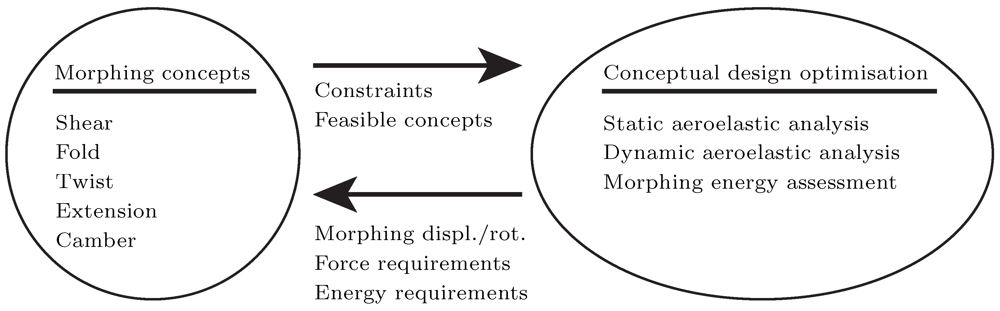
3. Assessment of Actuator Force and Morphing Deformation Aerodynamic Energy
The actuator force and energy must be evaluated on the morphing aircraft system level since specific morphing concepts are not known a priori for generic morphing aircraft. Therefore, the morphing aircraft level and the specific morphing concept level are decoupled. This methodology is explained in more detail in Werter and De Breuker [
22]. The basic idea behind this methodology is shown in
Figure 1.
It can be seen in
Figure 1 that aeroelastic analyses are used on the aircraft level to assess the aerodynamic performance of the wing including structural effects. Especially for morphing aircraft, the structural and aerodynamic level cannot be decoupled. There is always a tradeoff between the aerodynamic performance gains due to morphing and the weight penalties associated with these. The aerodynamic performance is dependent on the shape of the wing, which is governed by the structural flexibility. The weight penalties are due to both the structural mass of the morphing wing and the additional systems required for morphing. This paper focuses on a part of the morphing system weight, namely the actuators, actuation weight and batteries. The weight of these three is partially determined by the actuation force and energy. The use of an aeroelastic model is very convenient in their analysis, as we will demonstrate below.
De Breuker et al. [
21] developed an aeroelastic analysis framework for the analysis of generic morphing aircraft without the need to know the details about specific morphing concepts. This framework was later expanded by Werter and De Breuker [
22]. The basic idea is that the overall morphing wing deformations are decomposed in a combination of individual morphing deformations such as folding, camber, twist, extension and sweep. These individual deformation modes are parameterised by their respective rotation angle or displacement. The combination of morphing rotations and displacements results in the morphed shape which should yield optimal aerodynamic performance for the given flight condition. The essential question is how to obtain the forces or moments
associated with this displacement or rotation
to assess the actuation system and actuator weight penalty due to the morphing manoeuvre. Since we are using an aeroelastic model, this can be done by differentiating the strain energy
in the entire wing with respect to the morphing deformation. The strain energy is evaluated for the aeroelastic equilibrium condition at a particular morphed configuration:
where
is the stress resultant force vector and
are the nodal displacements. Since the morphing manoeuvre from configuration
A to configuration
B is nonlinear in general, and since the aerodynamic forces are changing during the morphing manoeuvre, the morphing manoeuvre needs to be split up into
n parts, and the actuation force
can be evaluated for each intermediate deformation. Integrating the changing actuation force over the morphing deformation yields the morphing energy
:
The description above also shows that, as already indicated in the previous section, the actuation forces and spent energy are dependent on the flight conditions. Therefore, it must be investigated in which order various morphing deformations have to be applied to morph from configuration A to configuration B, and at what flight condition. This will be demonstrated in the next section with a numerical example.
4. Results
We will show the benefits of morphing scheduling in this section. This obviously assumes a priori that there is a need for a combination of morphing mechanisms. However, one should always assess first whether a (combination of) morphing mechanism(s) is needed to design an optimal aircraft for a particular mission. This should be done using a tradeoff of the performance benefits of using morphing mechanisms including their weight penalty. An important maxim to keep in mind when designing an advanced aircraft is that one should not morph for the sake of morphing.
A small UAV which was optimised for minimal drag at different flight points was selected to demonstrate the importance of the flight condition at which a morphing manoeuvre is carried out as well as the order in which various morphing deformations are carried out. In the case of the present paper, the focus was on the morphing deformation from an optimal takeoff configuration to an optimal high-speed configuration in trimmed condition. The properties of the UAV are listed in
Table 1.
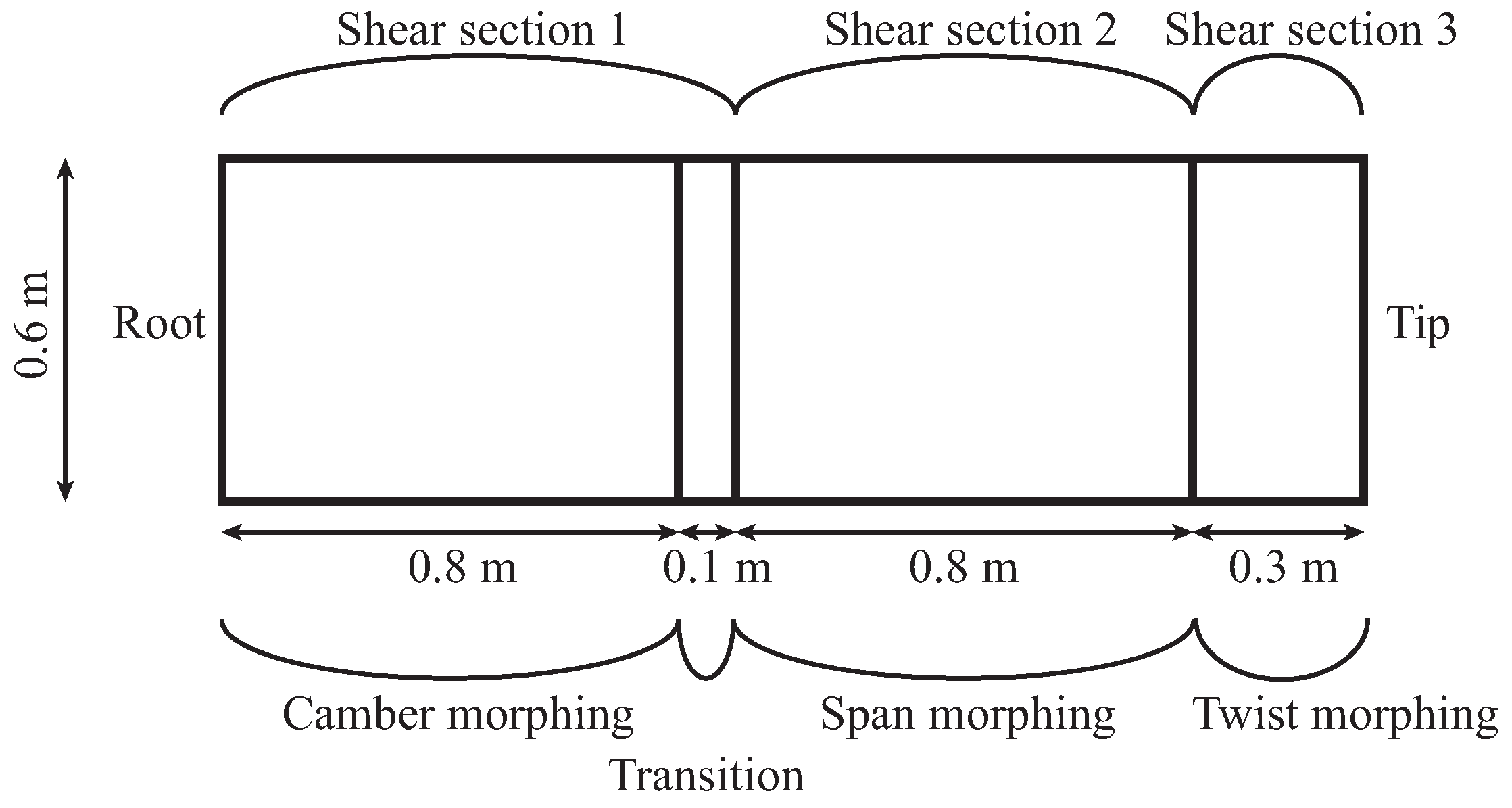
The UAV wing is able to morph by extending its span, shearing its sweep angle, twisting and changing its camber. The bounds on these four morphing parameters are given as:
Semi-span extension: 1.66 m → 2.00 m,
Twist angle: 0 deg →−5 deg (indicating washout),
Shear angle: 0 deg → 30 deg (indicating sweep back),
Camber: NACA2510 → NACA6510.
All four variables are defined as continuous variables between the aforementioned bounds. The airfoil camber is defined from 2% camber of the NACA2510 airfoil to 6% camber of the NACA6510 airfoil and varies linearly in the camber morphing section between both ends. The UAV wing was then optimised using the models and gradient-based optimisation methodologies as specified in [
21,
22]. The initial conditions were 15 deg sweep and zero twist for both the takeoff and high-speed case. Furthermore, the takeoff case had a fully extended span and a NACA3510 airfoil, while the high-speed initial guess was a fully retracted span and the NACA2510 airfoil. The morphing parameters were distributed over the entire wing as is depicted in
Figure 2.
The optimisation resulted in a drag for the takeoff case of 5.93 N and for the high-speed case of 7.37 N. These drag values are results from wings with morphed parameters as shown in
Table 2.
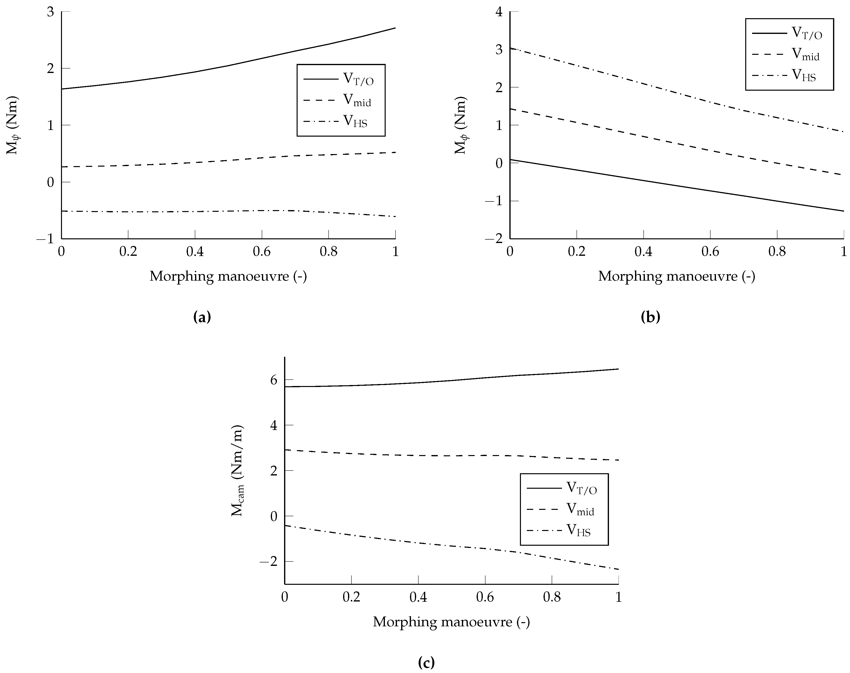
Two morphing transition options are investigated to illustrate the dependency of the actuation requirements on flight condition and morphing order. First, a case is analysed where all four morphing deformations happen concurrently linearly varying from the takeoff configuration to the high-speed configuration to investigate the dependency on flight condition. Condition 0 corresponds to the takeoff configuration and condition 1 to the high-speed configuration. The actuation forces of these morphing manoeuvres are evaluated at three velocities: (i) at takeoff velocity
; (ii) at a velocity
which is the average of the takeoff and the high-speed velocity; and (iii) at the high-speed velocity
. The corresponding morphing actuation moments for the different morphing mechanisms are shown in
Figure 3. For the sake of brevity, the actuation moment required for shear morphing is only shown for shear section 1 and the actuation moment required for camber morphing is only shown for the leading edge (
–
chord) about the mid chord at the wing root. Similar conclusions can be drawn for the other shear sections and camber locations.
It is immediately obvious from inspection of
Figure 3 that the choice of flight condition plays an important role in the magnitude of the actuation forces required to carry out the morphing manoeuvre. The difference in actuation requirement often exceeds 100%. Furthermore, it is also obvious that it is beneficial for certain morphing deformations to be carried out at takeoff speed, which other morphing deformations should be carried out at the high speed configuration in order to minimise the actuation forces. One could potentially distribute the complete morphing manoeuvre over a speed range.
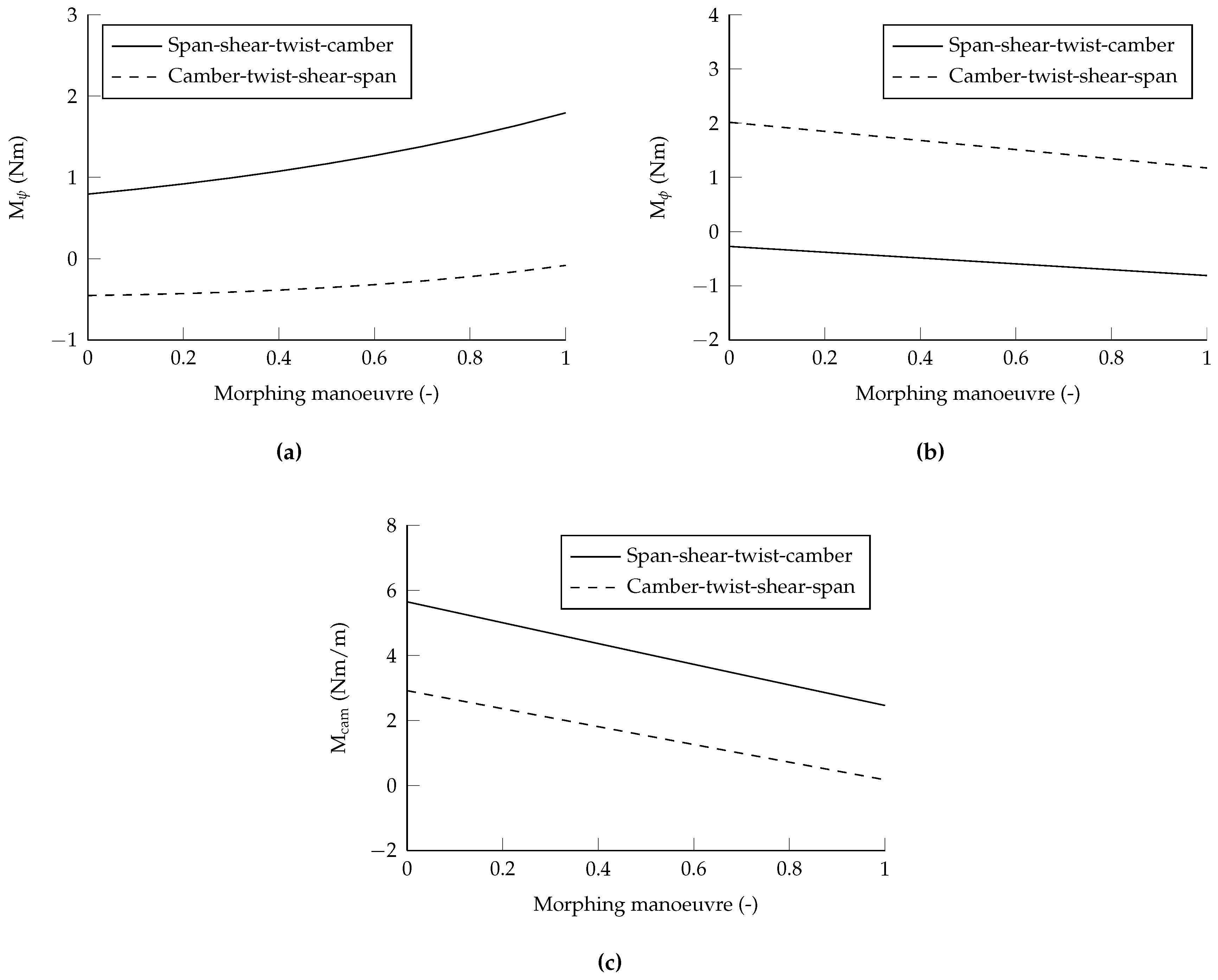
Secondly, a case is analysed where the velocity is kept constant at
, but the morphing deformations are carried out sequentially to investigate the dependency on the morphing order. With four morphing mechanisms, 24 cases are possible permutatively. For the sake of brevity, and just to illustrate the importance of the choice of a certain morphing sequence on the actuation requirements of a morphing aircraft, two reciprocal cases were chosen:
Other sequential combinations will yield different numerical results, but similar conclusions can be drawn. The corresponding morphing actuation moments are shown in
Figure 4. The influence here is very noticeable. Although only two morphing sequences are selected as an illustration, it is obvious that Sequence 2 is more beneficial for shear and camber, while Sequence 1 is preferred for the twist morphing moment. This tradeoff will be become even more complex when more morphing sequences are evaluated.
The results are interpreted and discussed further in the subsequent Discussion section.
5. Discussion
The goal of this paper is to illustrate the dependency of morphing actuation force and energy requirements on the flight condition and the order in which the morphing deformations are carried out as was already mentioned in the problem statement. It is obvious that the morphing actuation forces are dependent on the flight condition when looking at
Figure 3. However, there is not necessarily one flight condition at which all morphing actuation forces are minimised when comparing
Figure 3a,b. Therefore, a tradeoff needs to be made. Furthermore, aerodynamic forces that are beneficial when morphing from configuration
A to
B, are counter productive when morphing from configuration
B to
A. Therefore, a different tradeoff has to be made when morphing from configuration
B to
A and a different flight condition might be the optimal flight condition for morphing as compared to morphing from configuration
A to
B.
A similar conclusion can be drawn when deciding on the order in which the different morphing manoeuvres are carried out when looking at
Figure 4. For example, it is better to use morphing Sequence 2 as illustrated in
Figure 4a,c for shear and camber morphing. On the other hand, it is better to use morphing sequence 1 for twist morphing. A more detailed tradeoff can even be made when not only morphing from configuration
A to configuration
B in one stage, but also considering morphing to intermediate configurations and alternating the different morphing deformation sequences.
It must be noted that only actuation force is shown in the Results section. Our earlier argument also included actuation energy to reduce battery weight. Both the actuation force and energy are equivalent in the presented cases because the morphing manoeuvres were equal, namely varying linearly between the takeoff and high speed configurations. However, when the path from one optimal configuration to another optimal configuration would be varied as well, the energy would also become an independent objective to minimise.
6. Conclusions
In conclusion, a smart selection of the flight condition at which to morph and the sequence of morphing deformations will result in a lighter actuation system, smaller energy requirements, reduced aircraft weight and, ultimately, improved aircraft performance.
Acknowledgments
The work presented herein has been partially funded by the European Community’s Seventh Framework Programme (FP7) under the Grant Agreement 314139. The CHANGE project (Combined morphing assessment software using flight envelope data and mission based morphing prototype wing development) is a Level 1 project funded under the topic AAT.2012.1.1-2. involving 9 partners. The project started on 1 August 2012.
Author Contributions
Roeland De Breuker wrote the Abstract, the Introduction, and the Problem Statement, Assessment and Results sections. Noud Werter generated the results, co-wrote the Results section and wrote the Discussion and Conclusions section. The morphing analysis and design framework used to generate the results is a joint effort of both authors.
Conflicts of Interest
The authors declare no conflict of interest.
Abbreviations
The following abbreviations are used in this manuscript:
| ACARE | Advisory Council of Aeronautics Research in Europe |
| AFRL | Air Force Research Lab |
| DARPA | Defence Advanced Research Projects Agency |
| DLR | German Aerospace Centre |
| EC | European Commission |
| EU | European Union |
| NASA | National Aeronautics and Space Administration |
| UAV | Uninhabited Aerial Vehicle |
| USA | United States of America |
References
- European Commission. Flightpath 2050: Europe’s Vision for Aviation; Maintaining Global Leadership and Serving Society’s Needs; Report of the High-Level Group on Aviation Research; Policy/European Commission, Publications Office of the European Union: Luxembourg, 2011. [Google Scholar]
- Barbarino, S.; Bilgen, O.; Ajaj, R.M.; Friswell, M.I.; Inman, D.J. A Review of Morphing Aircraft. J. Intell. Mater. Syst. Struct. 2011, 22, 823–877. [Google Scholar] [CrossRef]
- Barbarino, S.; Saavedra Flores, E.I.; Ajaj, R.M.; Dayyani, I.; Friswell, M.I. A review on shape memory alloys with applications to morphing aircraft. Smart Mater. Struct. 2014, 23, 063001. [Google Scholar] [CrossRef]
- Dayyani, I.; Shaw, A.; Saavedra Flores, E.; Friswell, M. The mechanics of composite corrugated structures: A review with applications in morphing aircraft. Compos. Struct. 2015, 133, 358–380. [Google Scholar] [CrossRef]
- Gomez, J.C.; Garcia, E. Morphing unmanned aerial vehicles. Smart Mater. Struct. 2011, 20, 103001. [Google Scholar] [CrossRef]
- Kuder, I.K.; Arrieta, A.F.; Raither, W.E.; Ermanni, P. Variable stiffness material and structural concepts for morphing applications. Prog. Aerosp. Sci. 2013, 63, 33–55. [Google Scholar] [CrossRef]
- Sun, J.; Guan, Q.; Liu, Y.; Leng, J. Morphing aircraft based on smart materials and structures: A state-of-the-art review. J. Intell. Mater. Syst. Struct. 2016, 23. [Google Scholar] [CrossRef]
- McGowan, A.M.R.; Washburn, A.E.; Horta, L.G.; Bryant, R.G.; Cox, D.E.; Siochi, E.J.; Padula, S.L.; Holloway, N.M. Recent results from NASA’s Morphing Project. In Proceedings of the SPIE Conference on Smart Structures and Materials, San Diego, CA, USA, 28 February–2 March 2002; pp. 97–111.
- Weisshaar, T. Morphing Aircraft Technology—New Shapes for Aircraft Design; Technical Report RTO-MPAVT-141; NATO: Washington, DC, USA, 2006. [Google Scholar]
- Martin, E.T.; Crossley, W.A. Multiobjective aircraft design to investigate potential geometric morphing features. In Proceedings of the AIAA’s Aircraft Technology, Integration, and Operations (ATIO), Los Angeles, CA, USA, 1–3 October 2002.
- Peters, C.; Roth, B.; Crossley, W.A.; Weisshaar, T.A. Use of design methods to generate and develop missions for morphing aircraft. In Proceedings of the 9th AIAA/ISSMO Symposium on Multidisciplinary Analysis and Optimization, Atlanta, GA, USA, 4–6 September 2002.
- Raymer, D.P.; Crossley, W.A. A Comparative Study of Genetic Algorithm and Orthogonal Steepest Descent for Aircraft MDO. In Proceedings of the 40th AIAA Aerospace Sciences Meeting & Exhibit, Reno, NV, USA, 14–17 January 2002.
- Roth, B.; Peters, C.; Crossley, W.A. Aircraft sizing with morphing as an independent variable: Motivation, strategies and investigations. In Proceedings of the AIAA’s Aircraft Technology, Integration, and Operations (ATIO), Los Angeles, CA, USA, 1–3 October 2002.
- Joshi, S.P.; Tidwell, Z.; Crossley, W.A.; Ramakrishnan, S. Comparison of morphing wing strategies based upon aircraft performance impacts. In Proceedings of the 45th AIAA/ASME/ASCE/AHS/ASC Structures, Structural Dynamics & Materials Conference, Palm Springs, CA, USA, 19–22 April 2004.
- Frommer, J.; Crossley, W.A. Enabling continuous optimization for sizing morphing aircraft concepts. In Proceedings of the 43rd AIAA Aerospace Sciences Meeting and Exhibit, Reno, NV, USA, 10–13 January 2005.
- Skillen, M.D.; Crossley, W.A. Developing response surface based wing weight equations for conceptual morphing aircraft sizing. In Proceedings of the 46th AIAA/ASME/ASCE/AHS/ASC Structures, Structural Dynamics and Materials Conference, Austin, TX, USA, 18–21 April 2005.
- Skillen, M.D.; Crossley, W.A. Modeling and Optimization for Morphing Wing Concept Generation; Technical Report CR-2007-214860; NASA: Washington, DC, USA, 2007.
- Skillen, M.D.; Crossley, W.A. Morphing Wing Weight Predictors and Their Application in a Template-Based Morphing Aircraft Sizing Environment II, Part II: Morphing Aircraft Sizing via Multi-Level Optimization; Technical Report CR-2008-214903; NASA: Washington, DC, USA, 2008.
- Cavagna, L.; Ricci, S.; Travaglini, L. NeoCASS: An integrated tool for structural sizing, aeroelastic analysis and MDO at conceptual design level. Prog. Aerosp. Sci. 2011, 47, 621–635. [Google Scholar] [CrossRef]
- Cavagna, L.; De Gaspari, A.; Riccobene, L.; Ricci, S. NeoCASS+: A Conceptual Design and Simulation Framework for Morphing Aircraft. J. Aerosp. Sci.. Technol. Syst. 2013, 92, 52–60. [Google Scholar]
- De Breuker, R.; Abdalla, M.M.; Gürdal, Z. A Generic Morphing Wing Analysis and Design Framework. J. Intell. Mater. Syst. Struct. 2011, 22, 1025–1039. [Google Scholar] [CrossRef]
- Werter, N.P.M.; De Breuker, R. A framework for the aeroelastic analysis and design of generic morphing wings. In Proceedings of the 23rd AIAA/AHS Adaptive Structures Conference, Kissimmee, FL, USA, 5–9 January 2015.
© 2016 by the authors; licensee MDPI, Basel, Switzerland. This article is an open access article distributed under the terms and conditions of the Creative Commons Attribution (CC-BY) license (http://creativecommons.org/licenses/by/4.0/).


