Article

Manganese and Zinc Spinel Ferrites Blended with Multi-Walled Carbon Nanotubes as Microwave Absorbing Materials

Electrical and Computer Engineering, University of Connecticut, Storrs, CT 06269-4157, USA
*
Authors to whom correspondence should be addressed.
These authors contributed equally to this work.
Aerospace 2017, 4(1), 2; https://doi.org/10.3390/aerospace4010002
Submission received: 27 October 2016 / Revised: 10 January 2017 / Accepted: 11 January 2017 / Published: 14 January 2017
(This article belongs to the Special Issue Adaptive/Smart Structures and Multifunctional Materials 2016)

Abstract

:
Magnetic and dielectric materials can be blended to enhance absorption properties at microwave frequencies, although the materials may have relatively weak attenuation capabilities by themselves. The specific goal of this work is to enhance microwave absorption properties of materials with interesting dielectric behavior by blending them with magnetic materials based on transition metals. The synthesized Mn1−xZnxFe2O4 (x = 0.0 and 1.0) spinel ferrite nanoparticles (MZF NPs) were blended with commercial multi-walled carbon nanotubes (MWCNTs) in various proportions with a binder matrix of paraffin. This simple and efficient process did not cause a significant variation in the energy states of MWCNTs. MZF NPs were synthesized with a citric acid assisted sol–gel method. Their electromagnetic characteristics and microwave absorption properties were investigated. These properties were derived from the microwave scattering parameters measured via the transmission line technique by using a vector network analyzer (VNA) in conjunction with an X band waveguide system. The return loss (RL) values of the samples were obtained from the electromagnetic constitutive parameters (permittivity and permeability). The results indicate that the minimum RL value and the bandwidth change significantly with the amount of ferrite material in the blend. These results encourage further development of MWCNTs blended with ferrite nanoparticles for broadband microwave applications.

Graphical Abstract

1. Introduction

Microwave absorbers are widely used in various defense and aerospace applications, such as designing “stealth” aircraft, camouflaging ground-based military assets against air-based radar surveillance, and constructing anechoic chambers (where the radar signatures of aircraft and other targets are experimentally measured). The objective of “stealth” and camouflage designs is to reduce the radar cross-section (RCS) of potential targets, i.e., to make aircrafts, vehicles, or hardware systems less detectable to hostile radar observation systems. Two approaches may be used to achieve a reduced RCS: shaping the target so that the signal coming from the radar is guided in the desired directions (less “backscatter”) and using radar-absorbing materials (RAMs) for attenuating the incoming signal. In morphing applications, where large shape changes may be expected, the first approach will have obvious limitations. Therefore, reducing RCS by means of adaptive/smart structures incorporating RAMs becomes even more important. In general, the design and application of RAMs has to be constrained by factors such as weight, production costs, and maintenance [1]. Morphing concepts often involve the existence of a suitable flexible skin, which has to be not only soft enough to permit shape changes but also rigid enough to withstand loads [2]. This paper presents novel soft-skin RAMs, which may have many potential applications including those in morphing scenarios.
Nonmetallic materials have been used in aircraft construction, most commonly for wings, tails and control surfaces. Examples [3] of this include boron/epoxy horizontal tail skins (used in the production of F14 aircrafts), boron/epoxy horizontal and vertical tail skins (F15 aircrafts), graphite-epoxy horizontal and vertical skins and control surfaces (F16 aircrafts), graphite-epoxy wing, forward fuselage and control surfaces (Av-8B), and graphite-epoxy control surfaces (Boeing 757). These materials can be integrated/covered with suitable RAMs to enhance microwave absorption or to minimize reflection.
RAMs can be categorized into two types: dielectric and magnetic absorbers, which means that the absorption is primarily due to their dielectric and magnetic characteristics, respectively. The absorption by multi-walled carbon nanotubes (MWCNTs) is related to their dielectric properties (complex permittivity), which depend on dielectric mechanisms, such as electronic polarization and ion polarization. On the other hand, transition metals, such as Fe, Ni, Co, Mn, and Zn, are magnetic materials, which rely on their magnetic properties (complex permeability) to attenuate microwaves. However, both dielectric and magnetic materials have relatively low absorption when they are used by themselves. It is possible to enhance absorption characteristics when dielectric materials (MWCNTs) are coated or blended with magnetic nanomaterials, such as transition metals or their ferrites, which are known for their microwave absorption properties [4,5].
Previous studies have used magnetic fillers, such as iron (Fe) [6], nickel (Ni) nanowires [7], hybrid materials consisting of magnetite nanocrystals [4], carbonyl iron particles [8], magnetite nanoparticle and hollow carbon fiber composites [9], carbon-encapsulated cobalt (Co) nanoparticles [10], Co [11], Ni and Co [12], zinc oxide whiskers [13], in conjunction with CNTs [14] and ZnO [15]. We investigated manganese and zinc spinel ferrite nanoparticles (MZF NPs) as filler materials because of their high flexibility, high electrical resistivity, enhanced magnetic properties at radio frequencies, and their super-paramagnetic behavior attributable to the nano-magnetic-sized particles. Moreover, MZF NPs were blended in the MWCNTs through a simple and efficient process that did not cause a significant variation in the energy states of MWCNTs. Our choice of MZF NPs is consistent with the previous studies that used transition metals without MWCNTs, such as Ni and Co [16], Co [17], nickel ferrite composites [18], NiCoZn spinel ferrites [19], Ni and Zn spinel ferrites [20], and MnZn ferrite/rubber [21]. Gama, Rezende, and Dantas [21] reported on the dielectric, magnetic and microwave absorption properties of rubber radar absorbing materials depending on the Mn–Zn volume fractions (prepared by the usual ceramic sintering method from a mixture of Fe2O3) and the thickness values of RAM in the 2–18 GHz frequency range. Our work differs from [21] in that MZF NPs (synthesized using a citric acid assisted sol–gel method) are used to implement the magnetic materials. Desirable features of spinel ferrites, such as their enhanced magnetic properties in the radio frequency region have attracted great interest in recent years [22]. Manganese ferrite (MnFe2O4) and zinc ferrite (ZnFe2O4) are common spinel ferrite materials and they have been used widely in microwave and magnetic recording applications [23]. We investigated the effect of MWCNTs on magnetic, dielectric, and microwave absorption properties of MnFe2O4 and ZnFe2O4 spinel ferrite RAMs according to their mass fractions.
To obtain the electromagnetic constitutive parameters (permittivity and permeability), we measured the scattering parameters in the X band with an Agilent PNA E8363B network analyzer (KEYSIGHT Technologies, Santa Rosa, CA, USA), in conjunction with a waveguide system combining samples of MZF NPs blended with MWCNTs. The electromagnetic constitutive parameters of the specimens were calculated from the measured scattering parameters using the Nicolson-Ross-Weir algorithm [24]. The return loss (RL) values for each sample were additionally obtained from the calculated complex permittivity and permeability values in order to assess their suitability as radar-absorbing materials.

2. Materials and Methods

2.1. Materials

The binder matrix used in this work is paraffin. Commercial MWCNTs, supplied by U.S. Research Nanomaterials, Inc., Houston, TX, USA, were used as a dielectric filler. Their main characteristics, as provided by the supplier, are listed in Table 1 [25].
Manganese and zinc spinel ferrites (MZF NPs) have been used as filler magnetic materials after their synthesis by a citric acid assisted sol–gel method, which will be discussed in detail in the next section. A schematic illustration of MZF NPs blended with MWCNTs in a paraffin host matrix is presented in Figure 1.

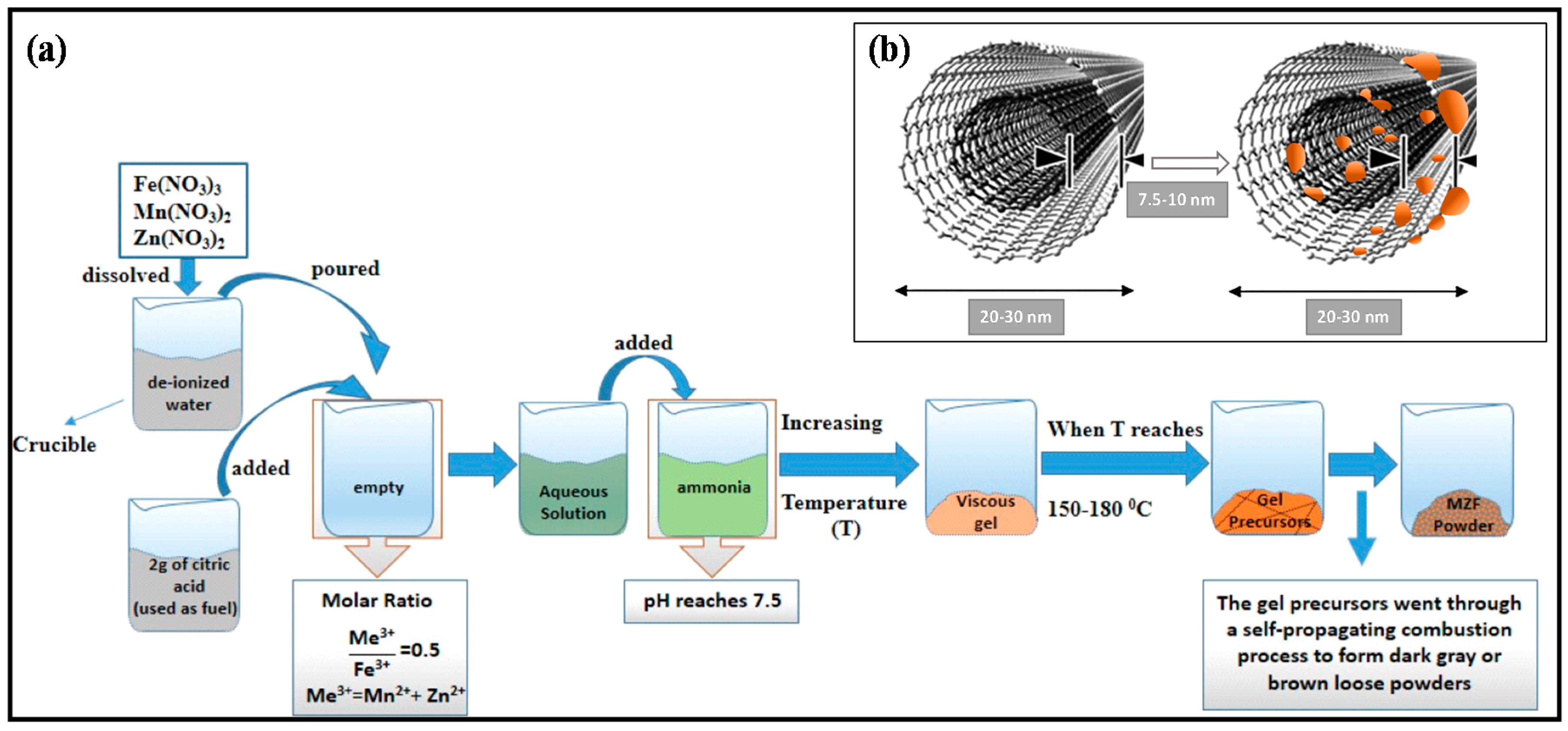
2.2. Preparation of Manganese and Zinc Ferrites (MZF)

Manganese and zinc ferrite particles in the present study were prepared by a citric acid assisted sol–gel method shown in Figure 1. The sol–gel method has a wide range of applications because of its high efficiency, large productivity, and low production temperatures and costs. Conventional industrial methods for the manufacturing of ceramic and glass need very high temperatures [23]. Therefore, in general, the sol–gel process is known as soft chemistry. In addition, the sol–gel method is a multipurpose process where the morphology, structure, and the composition of the final materials can be tuned by altering the hydrolysis and condensation reaction proportions [26]. Here, we have listed the steps of the sol–gel process, such as the homogeneous precursor solution with solid materials, jellification, aging step, desiccation step, and densification step [27]. The procedure of material preparation as reported by Demir et al. [28] was followed exactly (for more details on material preparation, please consult [28]). A schematic representation of the synthesis of Mn–Zn ferrite powder particles is given in Figure 1a.

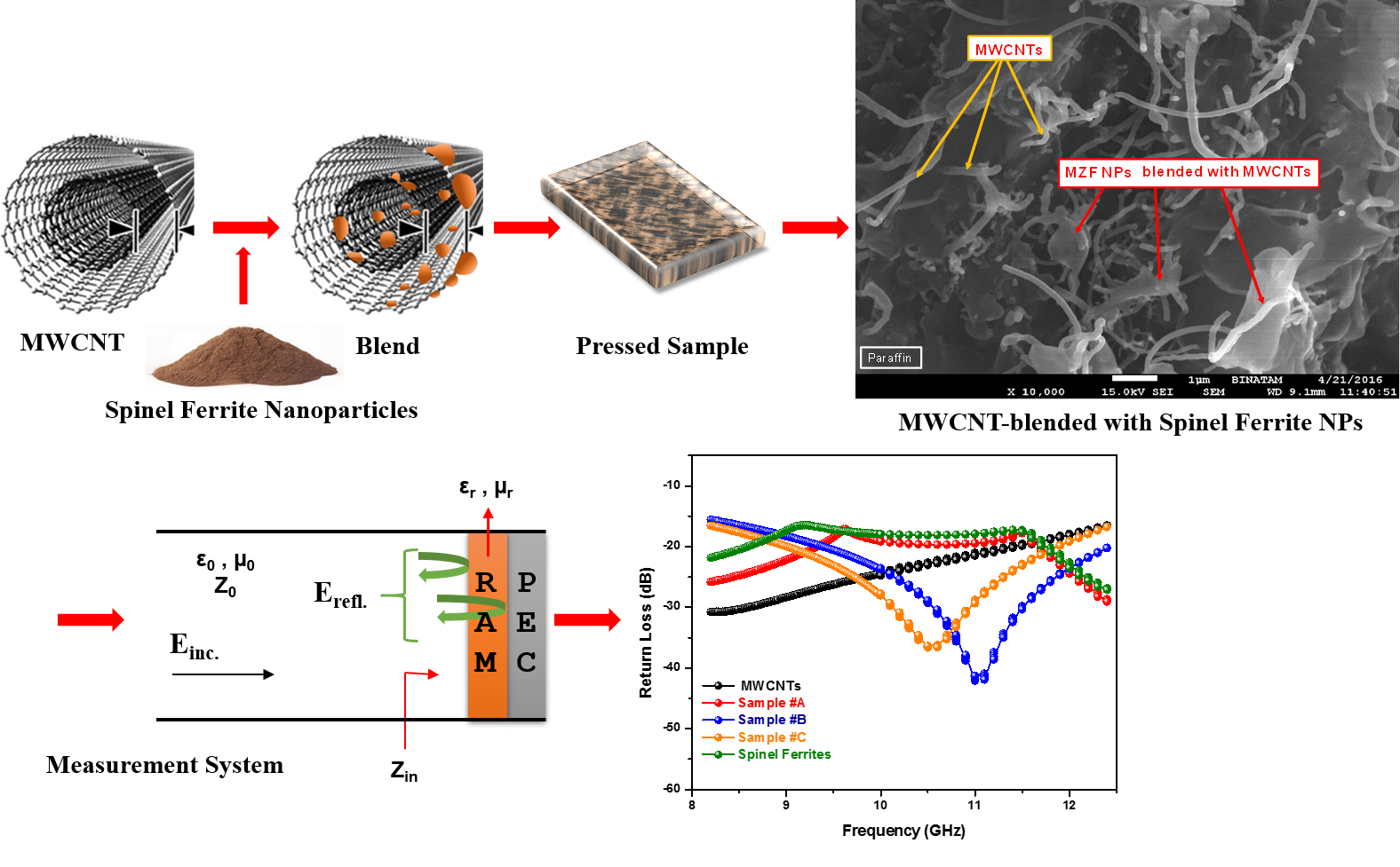
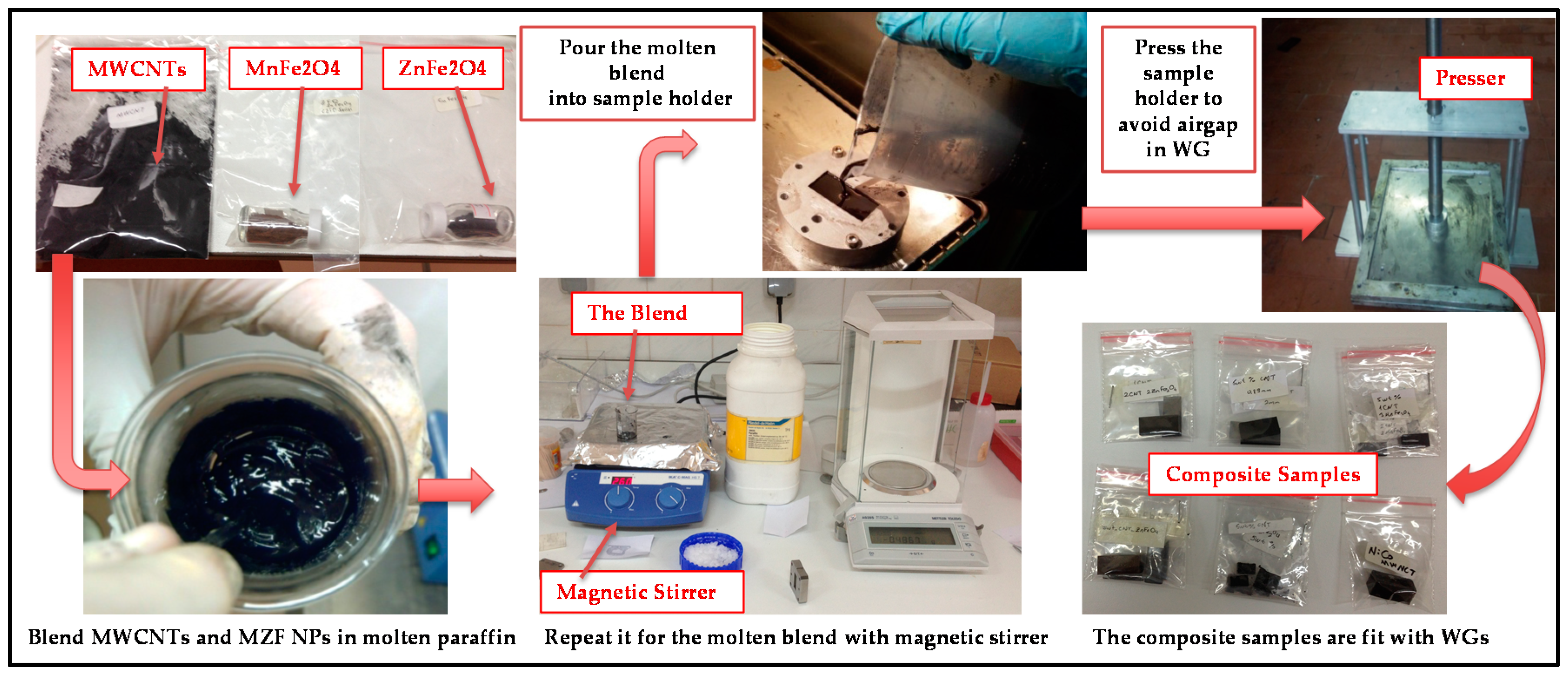
2.3. Preparation of Nanocomposite Samples

Six different MWCNTs-based magnetic nanocomposites were prepared with various mass proportions using a binder matrix of paraffin through a simple and efficient process. Obtaining homogeneous samples is crucial for reliable microwave measurements. One important aspect in the use of nanoparticles in composites is a random dispersion inside the matrix with the goal of obtaining homogeneous samples. Furthermore, mixing filler nanoparticles within paraffin and eliminating air bubble formation inside the blend are required to obtain a homogeneous dispersion. The fillers of MWCNTs and MZF NPs were blended together in a proportion of 60 wt % (the total filling amount) with 40 wt % of molten paraffin. In the present work, six absorber samples with different compositions were prepared with the steps of 25%–50%–75% (three of them for the fillers of MnFe2O4, and three of them for the fillers of ZnFe2O4). The proportion details for all RAM specimens are shown in Table 2. The process was carried out for the molten blend with the help of a “magnetic stirrer”, which includes a heating plate and which uses ultrasound waves to agitate particles. In the next step, the molten blend was poured into the sample holders, which were the same size as the waveguide cross-section.
Another important practical aspect for solid materials is to eliminate the air gap between the sample and the sample holder. An air gap between them can be a substantial source of error unless the sample face and the edges of sample are machined as flat/fit as the inner walls of the sample holder [29]. For this step, the sample holders, including the molten blend, were flattened with a presser to avoid any airgaps in the waveguide system. Then, the samples were ready for the microwave measurements in Figure 2.

2.4. Instrumentation

The crystalline structure of the resultant nanoparticles (MZF NPs) was characterized with an X-ray diffractometer (Rigaku D/Max—3C using Cu Kα radiation, Rigaku Innovative Technologies, Inc., Ettlingen, Germany) between 15 and 75 degrees in the 2θ range with a step size of 0.1 (2θ).
Fourier transform infrared (FT-IR) spectra of MZF NPs were carried out on a Bruker α-P by the attenuated total reflection (ATR) technique in transmission mode to explore the nature of the chemical bonds formed in the range between 4000 and 400 cm−1.
By using a vibrating sample magnetometer (LDJ Electronics Inc., Model 9600, Troy, MI, USA), Vibrating Sample Magnetometry (VSM) measurements were done. An external field of up to 15 kOe at room temperature is applied to carry out the magnetization measurements.
Scanning electron microscopy (SEM), was used to observe the amount of deposited material as MZF NPs filler particles. By using a JEOL (JSM-7001F SEM-EDS-EBL, JOEL USA, Inc., Peabody, MA, USA) scanning electron microscope, the surface morphology of the samples was analyzed. SEM was operated at an accelerating voltage of 15 kV.
Energy-dispersive X-Ray spectroscopy (EDX) measurements were performed at 13 keV with INCA Instruments (Oxford Inca system, Oxford Co. Ltd., Belfast, UK).
Microwave S-parameter measurements were done in the 8.2–12.4 GHz frequency range at room temperature using the transmission line technique with an Agilent PNA E8364B network analyzer along with a waveguide system from Agilent (the specific waveguide model is WR90, Santa Rosa, CA, USA).

3. Results and Discussion

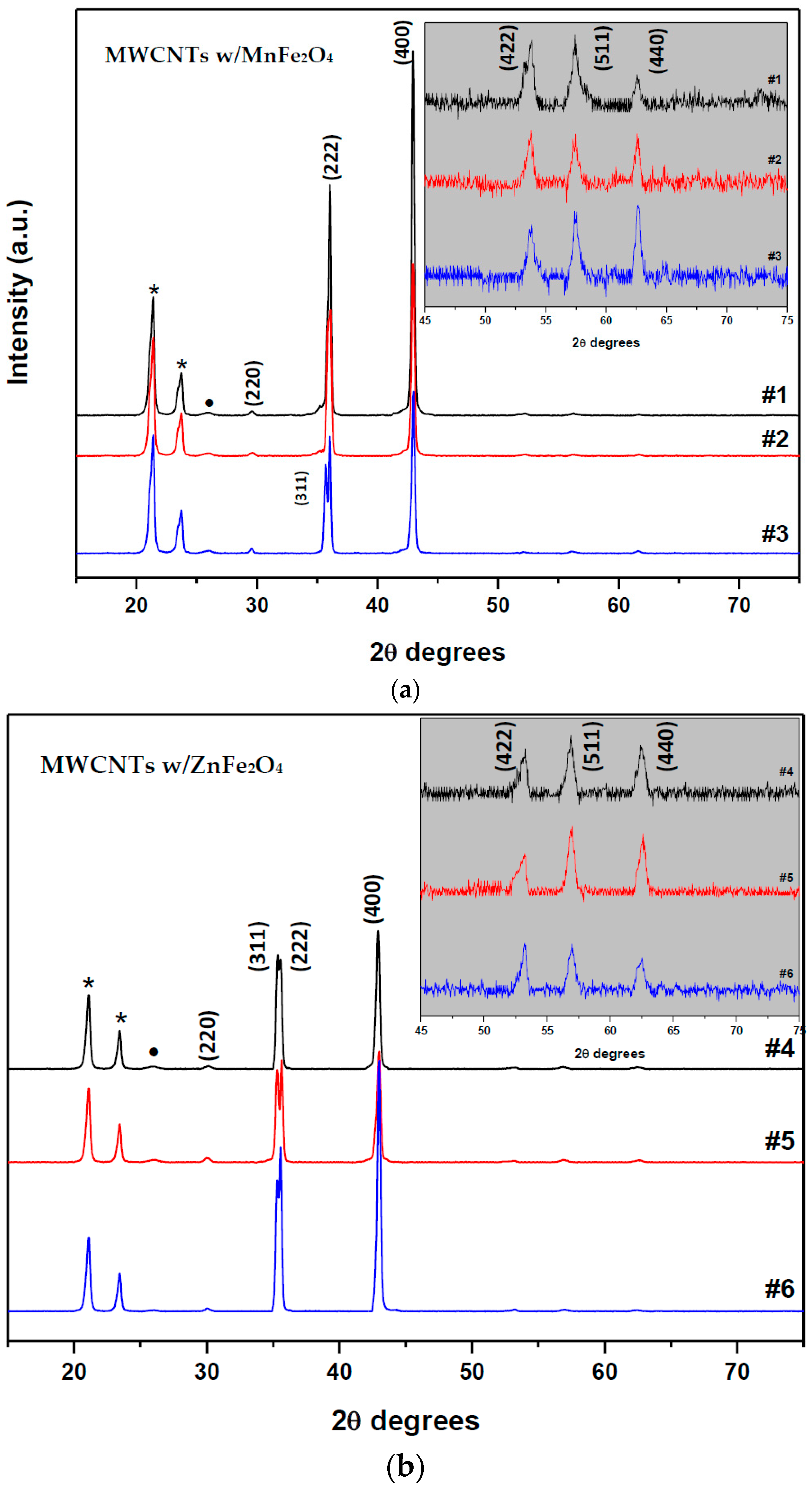
3.1. Morphology and Crystal Structure Characterization

The crystal structure of nanoparticles was identified with X-ray powder diffraction analysis, as shown in Figure 3a,b. The particle sizes for both MnFe2O4 and ZnFe2O4 samples were calculated by the well-known Sherrer’s formula [33] using the full width at half-maximum of intensity in the (400) plane of the spinel structure: L (nm) = 0.94λ/βcosθhkl. Here, L is the average crystallite size, β is the full width of the relevant diffraction peak (FWHM), λ the X-ray wavelength (1.5418 Å), and θhkl is the angle of the diffraction peaks. The experimental lattice constants (aexp) were calculated with the inter-planner distances; dhkl-values and Miller indices (hkl) based on Bragg’s equation:
n λ = 2 d h k l sin θ h k l
1 / d h k l 2 = ( h 2 + k 2 + l 2 ) / ( a exp ) 2
The diffraction peaks at 29.7°, 35.5°, 36.6°, 42.97°, 53.8°, 57.4°, and 62.65° could be assigned from Figure 3a, which correspond to (220), (311), (222), (400), (422), (511), and (440) planes of MnFe2O4, respectively. As shown in Figure 3a, the peaks were in good agreement with the standard MnFe2O4 card (JCPDS cards No. 74-2403, 74-2402, 10-0319), which indicate the samples had a face-centered cubic crystal structure. No secondary impurity phase was detected, hence, the absence of any additional peaks assigned to the graphite plane of MWCNTs. This means MWCNTs with ferrite nano-particles are relatively coated. The broadening of the diffraction peaks indicates the nano-crystalline nature of the materials. As shown in Figure 3a, the XRD peaks marked (*) at 21.46° and 23.82° were caused by the paraffin because of its regular crystallization [34]. The calculated mean crystallite size value of MnFe2O4 is found to be about 22 nm. The lattice constant (aexp) was calculated and found to be 8.4215 ± 0.0006. The diffraction peaks at 30°, 35.3°, 35.5°, 42.9°, 53.2°, 56.9°, and 62.5° could be assigned from Figure 3b, which correspond to (220), (311), (222), (400), (422), (511), and (440) planes of ZnFe2O4, respectively. As shown in Figure 3b, the peaks were in good agreement with the standard ZnFe2O4 card (JCPDS cards No. 82-1042, 82-1012, 79-1150, and reference code 01-089-4926), indicating the samples had face centered cubic crystal structure. As shown in Figure 3b, the XRD peaks marked (*) at 21.4° and 23.8° were caused by the paraffin due to its regular crystallization. An additional peak, the peak marked (•), was detected at 25.98° which corresponds to (002) planes of the MWCNTs. The calculated mean crystallite size value of ZnFe2O4 found to be about 29 nm. The lattice constant (aexp) was calculated and found to be 8.4306 ± 0.003 Å.

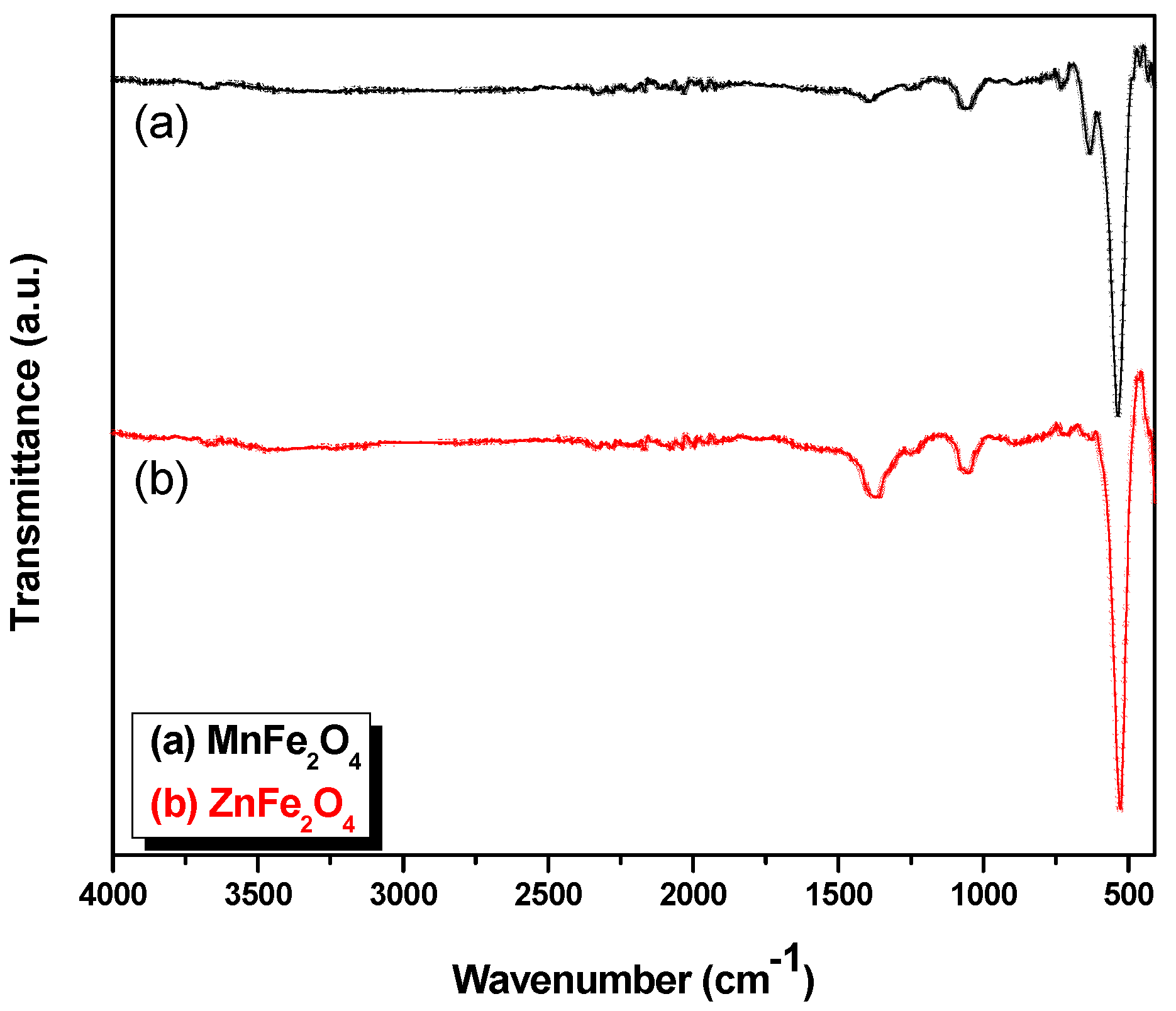
3.2. Fourier Transform Infrared (FT-IR) Analysis

The FT-IR spectra of the synthesized Mn1−xZnxFe2O4 NPs are presented with a step size of 0.2 (x = 0:0.2:1) in Figure 4, including the band positions of the investigated samples (just MnFe2O4 and ZnFe2O4) shown in Table 3. The FT-IR spectra has been discussed extensively in [28] and all details on the other step sizes of the FT-IR spectra are found therein. According to the geometrical configuration of the oxygen nearest neighbors in ferrites, the metal ions are located in two different sub-lattices. They are also designated as tetrahedral and octahedral sites [35]. The specimens contained insignificant amounts of organic residue, as shown in Figure 4.
The characteristic peaks of MnFe2O4 for Mn–O, ZnO and Fe–O bond stretching vibrations can be clearly observed at wave numbers 560 cm−1 in Figure 4 [36,37]. The peaks at 1380 and 1600 cm−1 are attributed to the C=O stretching modes, respectively, because of the coordination of the carboxylate groups of the citric acid by metal ions. It is believed that the observed two peaks on the left of the 600 cm−1 wavenumber belong to organic residues, which were used as fuel during the synthesis.

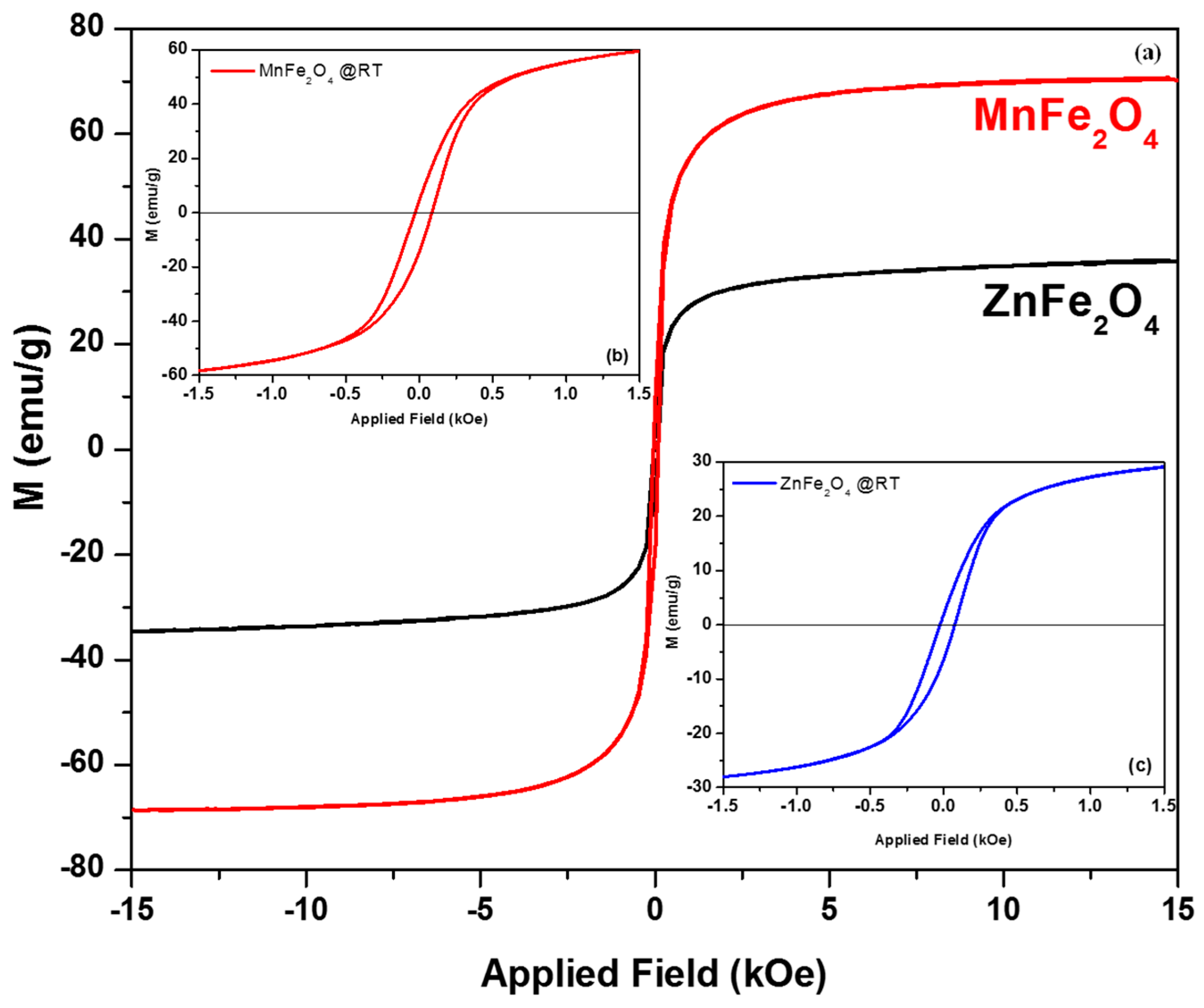
3.3. The Magnetization Measurements (VSM Analysis)

Magnetization curves (M versus H) of MZF NPs were measured at room temperature with an applied field of ±15 kOe. Figure 5b,c show the enlarged views in ±1.5 kOe demonstrating the hysteresis behavior for the synthesized MnFe2O4 and ZnFe2O4. The values of Mr, Ms, and Hc were determined versus Zn mole concentrations depending on Mn1−xZnxFe2O4 formula with a step size of 0.2 (0:0.2:1). Here, the values for just the synthesized MnFe2O4 and ZnFe2O4 NPs have been reported. The values of saturation magnetization (Ms), coercivity (Hc), and remnant magnetization (Mr) are determined from hysteresis loops. They are listed in Table 4.
The results from the hysteresis loops indicated that all of the composite magnetic spheres were magnetically soft at room temperature, when an external field was applied (Figure 5).
Due to these values, it can be argued that all samples exhibited super-paramagnetic behavior at room temperature. The observed Ms and Mr values of MnFe2O4 NPs were higher than those for ZnFe2O4 NPs. It can be explained by noting that Zn has no net magnetic moment. The values of Ms of MnFe2O4 are lower than the reported values for bulk MnFe2O4 (80 emu/g) [38,39]. Such behavior is ascribed to surface effects in nanoparticles. The values of Ms of ZnFe2O4 particles was much higher than the bulk Ms values of 5 emu/g [40]. Such behavior is related to cation distribution, which can change from a normal spinel structure to a mixed spinel structure [28].

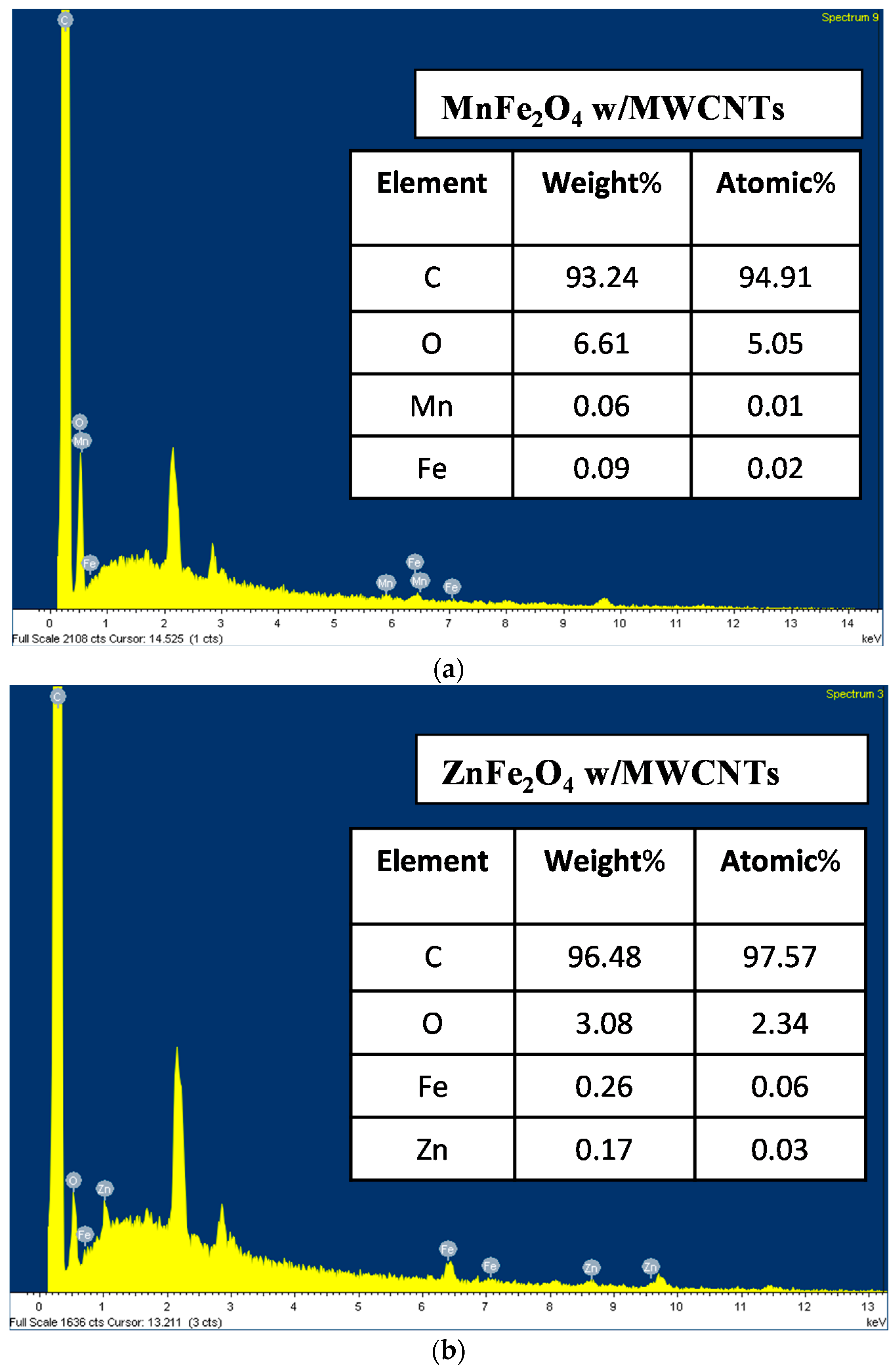
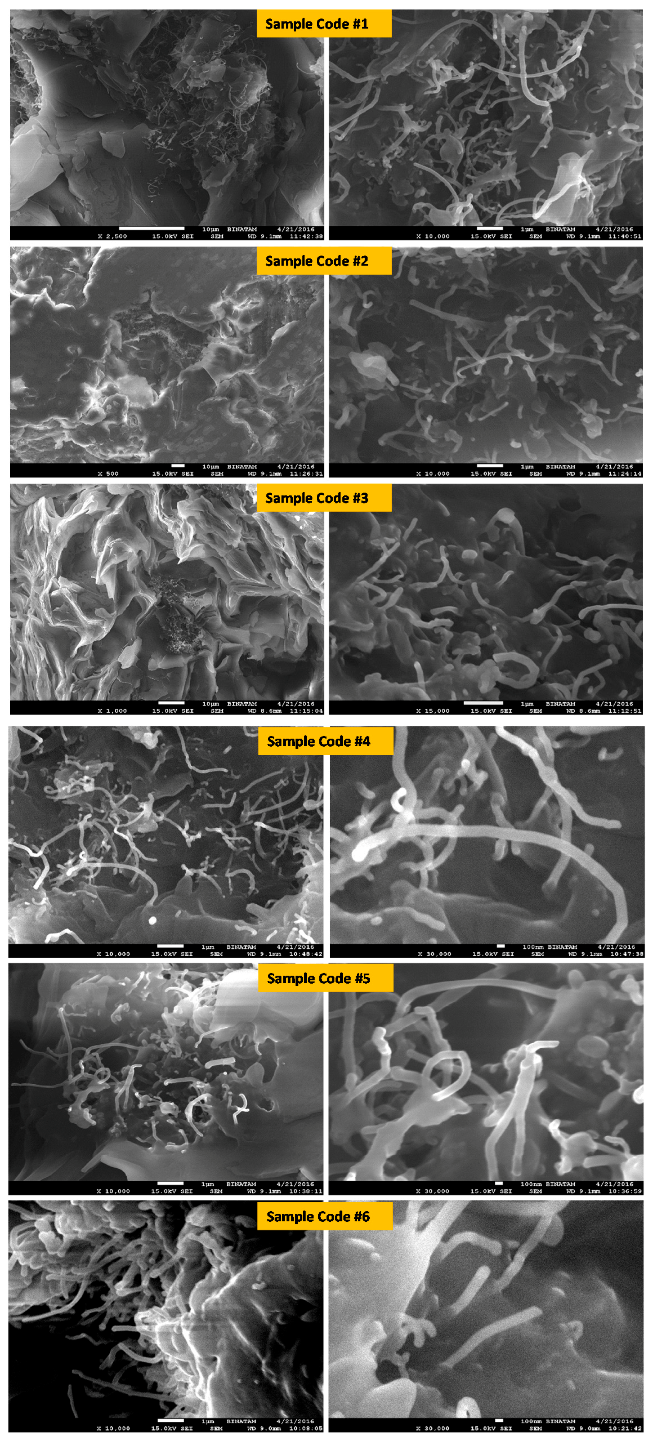
3.4. The Surface Morphology of the Samples (SEM) Analysis and the Energy Dispersive X-Ray (EDX)

SEM images of the nano-structured specimens are shown in Figure 6, which demonstrates the dispersion of MWCNTs particles and MnFe2O4 NPs as well as ZnFe2O4 NPs. The fillers were dispersed randomly in the host matrix. In addition, it is clearly seen that some of MWCNTs were coated/filled with MZF NPs. This result agrees with the XRD results, where the absence of any additional peaks implies that MWCNTs were coated with spinel ferrite nanoparticles.
The EDX technique provides the effective atomic concentration of different components in the top surface layers of solids. The energy dispersive X-ray (EDX) analysis of the specimens, as shown in Figure 7, was carried out to confirm the elemental composition of the specimens. The EDX spectrum confirms the presence of Mn, Fe, C, and O elementals, as well as Zn, Fe, C, and O elementals for the samples of MnFe2O4 with MWCNTs and ZnFe2O4 with MWCNTs, respectively. The other minor peaks might be due to the impurities in the starting materials. The relative atomic and weight abundance of Mn, Zn, Fe, and O species are presented in the tables on each EDX graph. The atomic ratios of Fe/Mn and Fe/Zn, found to be 2:1 by EDX analyses, confirmed the presence of MnFe2O4 and ZnFe2O4 nanoparticles on the MWCNT surfaces.

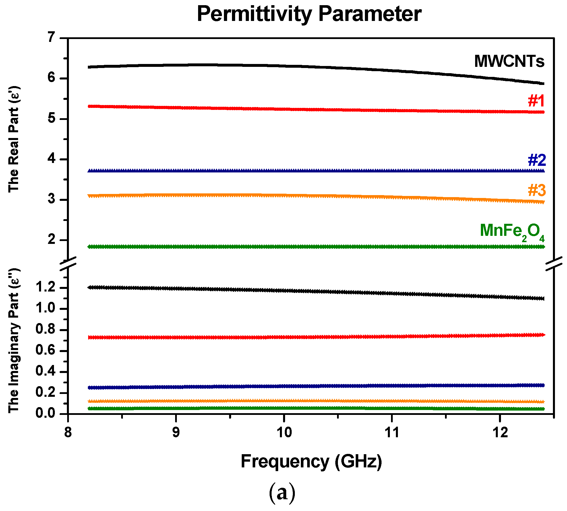
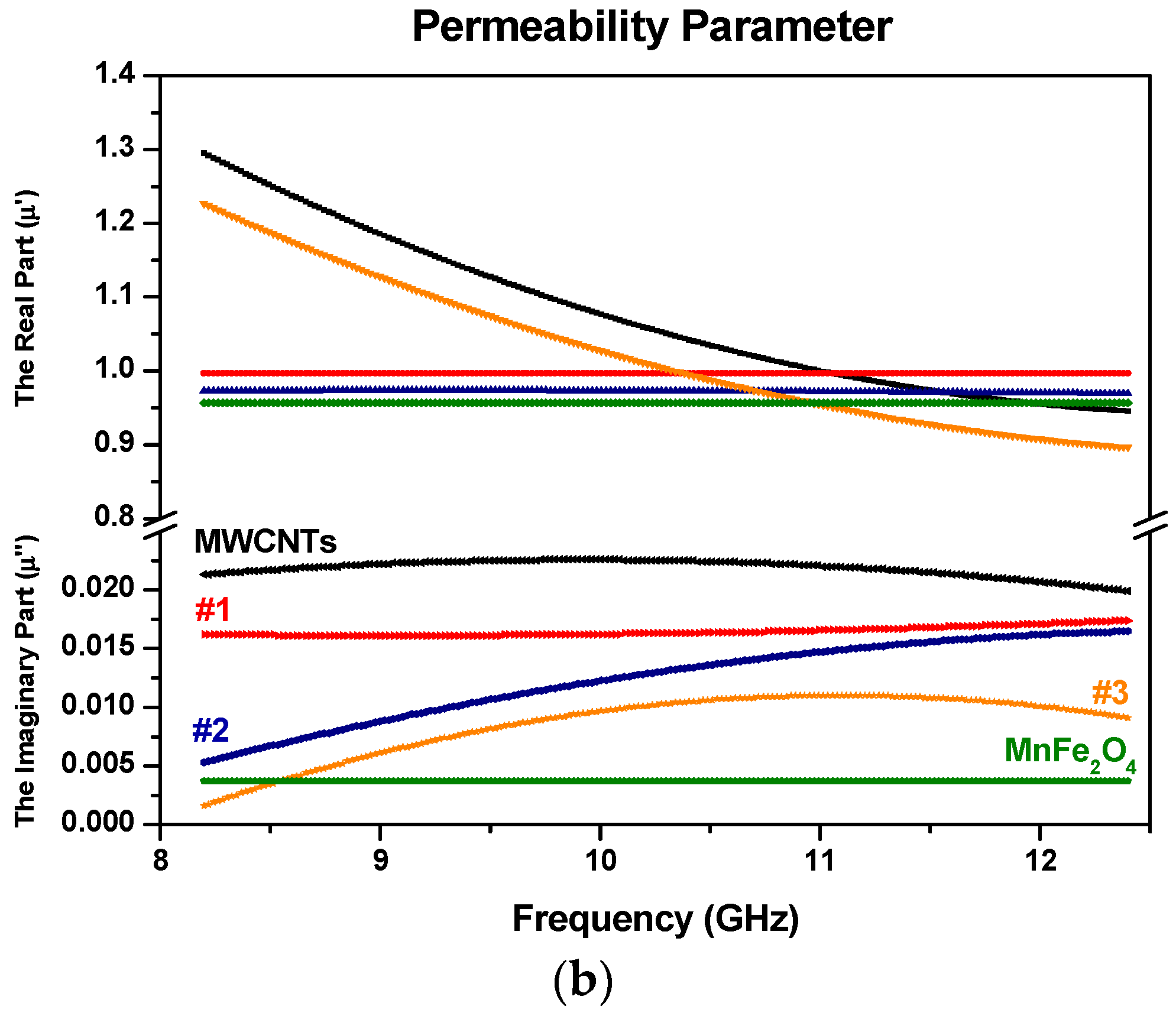
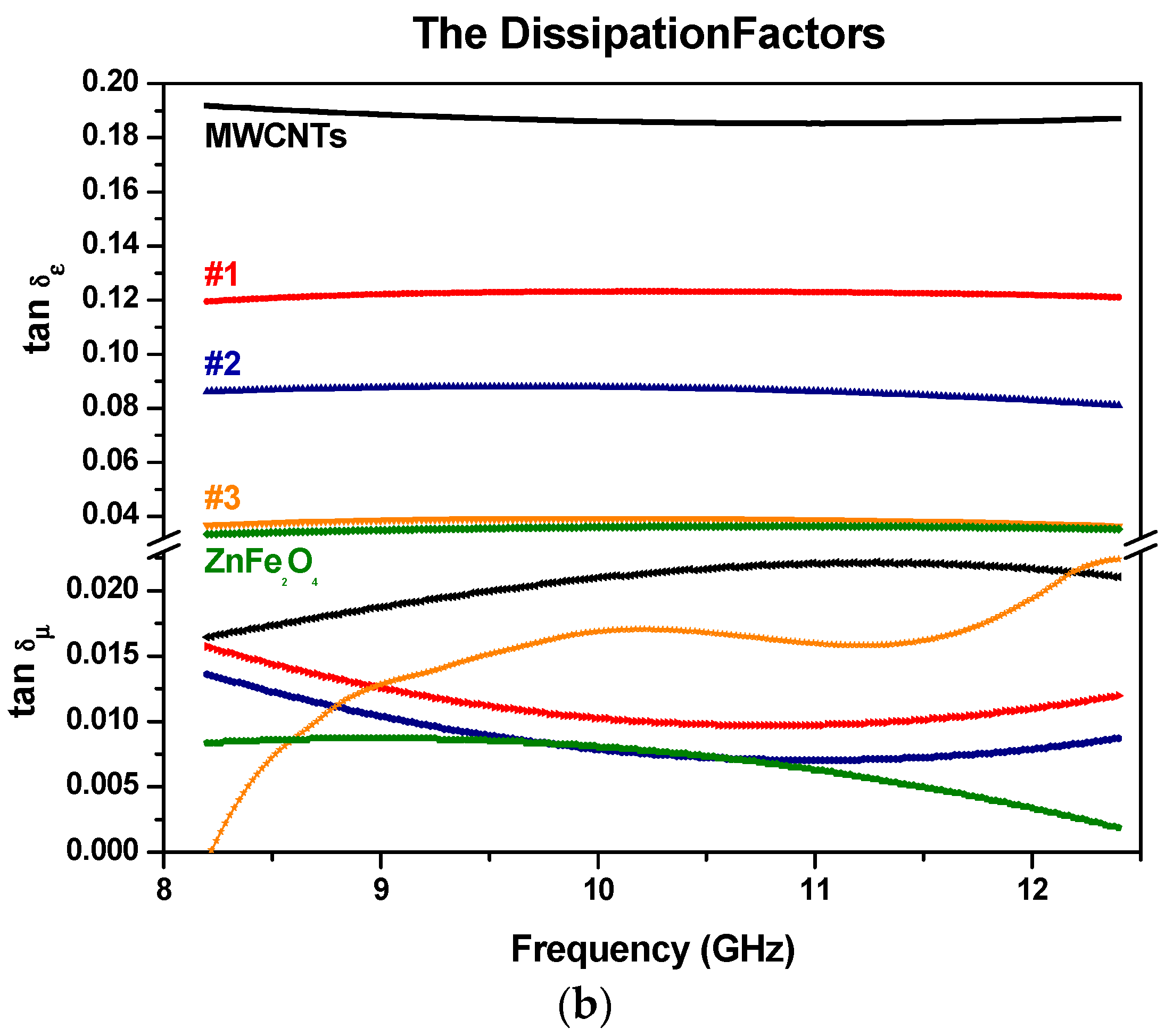
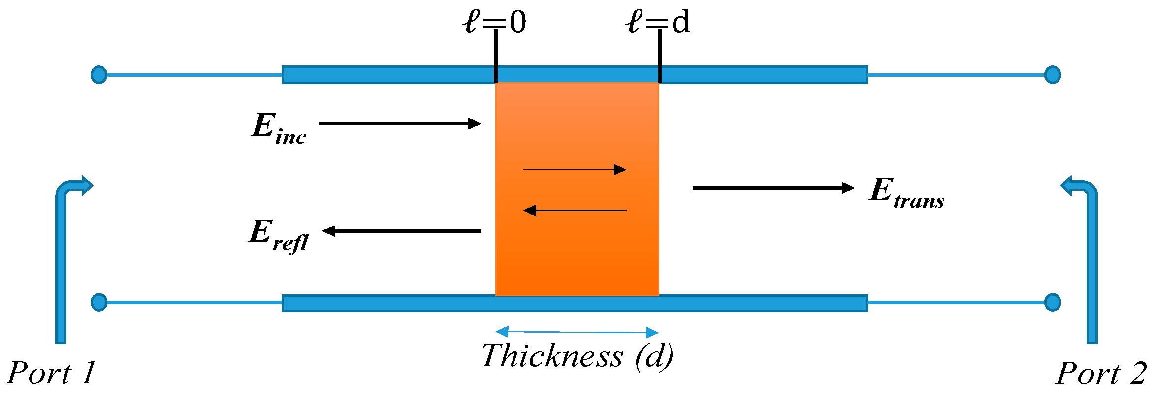
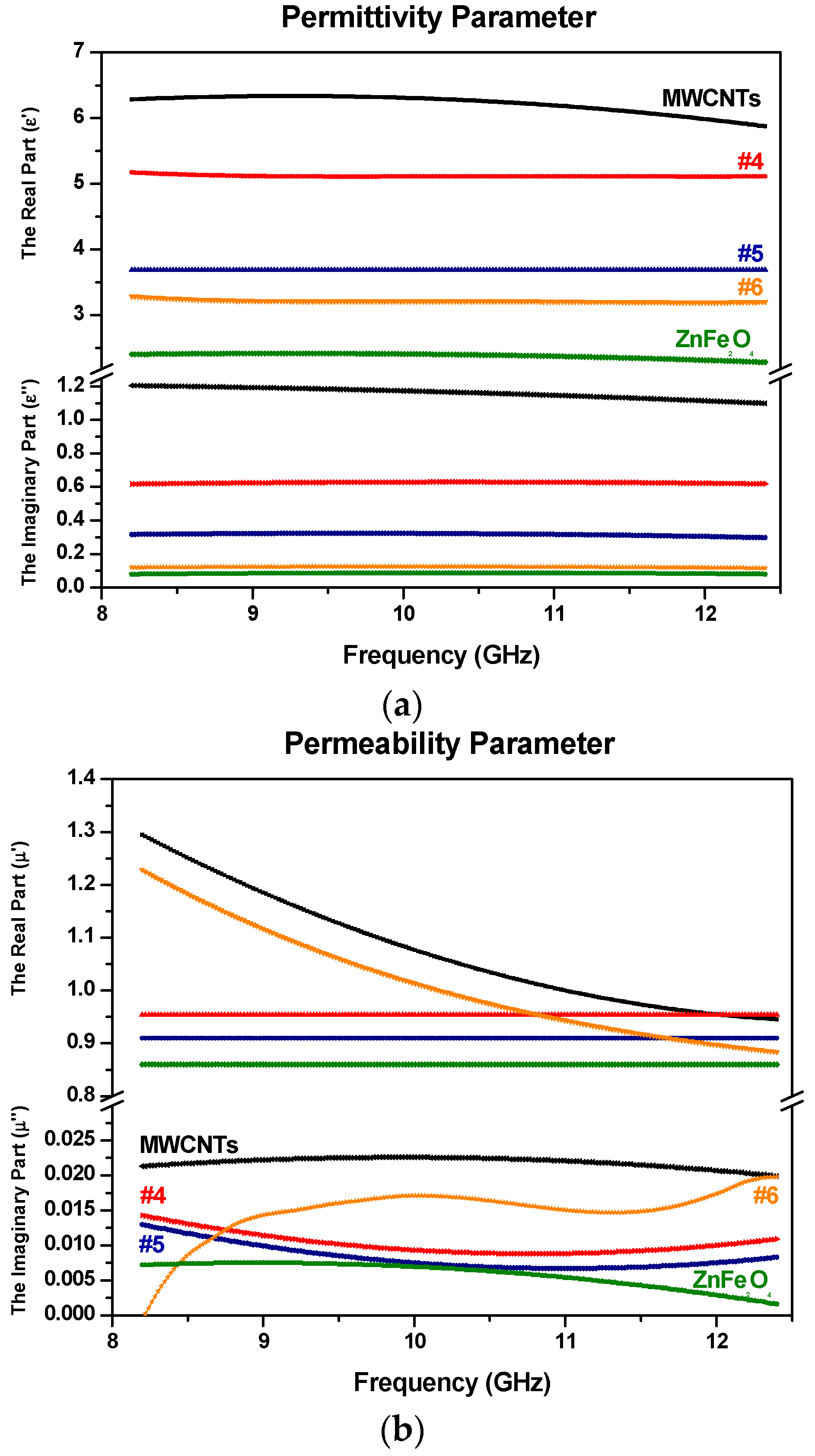
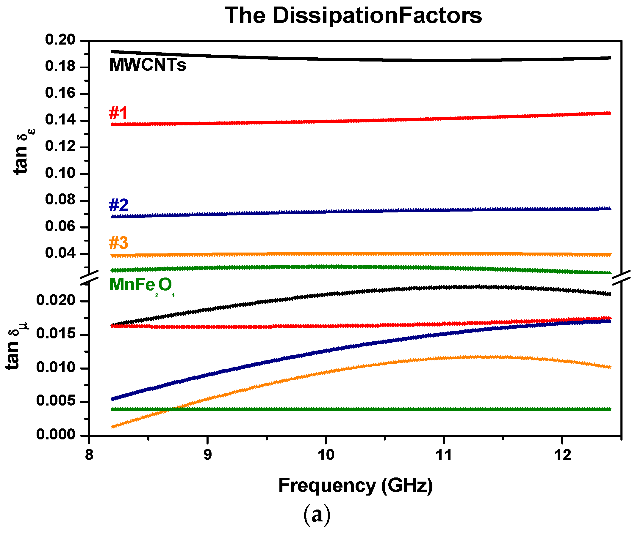
3.5. Electromagnetic Constitutive Parameters

The values of electromagnetic complex permittivity and permeability were calculated from the scattering parameters, such as S11 and S21, using the transmission line method with the Nicolson–Ross–Weir algorithm [24]. Reflection coefficient Γ is given by Γ = K ± ( K 2 1 ) where K = [ ( S 11 2 S 21 2 ) + 1 ] / 2 S 11 . The transmission coefficient T is given by T = [ ( S 11 + S 21 ) Γ ] / [ 1 ( S 11 + S 21 ) Γ ] . The permittivity and the permeability are calculated [24] from:
μ r = 1 + Γ ( 1 Γ ) Λ [ ( 1 λ 0 2 ) ( 1 λ c 2 ) ]
ε r = λ 0 2 μ r [ ( 1 λ c 2 ) ( 1 Λ 2 ) ]
1 Λ 2 = [ 1 2 π d ln ( 1 T ) ] 2
where λ0 is the wavelength of free-space; λc is the cut-off wavelength of the transmission line. The schematic illustration of microwaves transmitting through, and reflecting from, a sample in a waveguide transmission line is represented in Figure 8.
The complex constitutive parameters (dielectric permittivity and magnetic permeability) denote the dielectric and magnetic properties of materials as RAMs. The real components (εr’ and µr’) of the electromagnetic constitutive parameters represent the storage capability of electric and magnetic energy. Energy loss in materials is due to the imaginary part of the complex permittivity and complex permeability (εr” and µr”). Magnetic losses are more effective and sensitive than dielectric losses for microwave absorption. A small differences in permeability can even affect the microwave absorption properties of the materials [41].
Figure 9 and Figure 10 show the real and the imaginary parts of the relative permittivity and permeability of five different compositions of Mn or Zn ferrite and MWCNTs alloys, namely in 25% increments of weight ratios.
As shown in Figure 9a and Figure 10a, the real part of the permittivity of the specimens remained almost constant in the whole frequency range. The constancy means that there was a dominant polarization, in which the oscillation of the electric dipole moments was in phase or somewhat out of phase with the microwave frequencies [42]. Moreover, the atomic and electronic polarizations may take place within a period shorter than the period of a microwave signal. Both the direct current conductivity and the alternating current conductivity may cause the dielectric loss of the materials. It can be seen clearly by the following equation:
ε " = σ d c ( ω ε 0 ) + ε a c
It appears that the direct current conduction loss is inversely proportional to the frequency; hence, the reason for the increase in ε″ for pure MWCNTs with decreasing frequency at lower frequencies. In addition, it is noted that decreasing the loading amount of MWCNTs in the composites, the values of the real and the imaginary part of permittivity (ε′) decreased for both samples of MWCNTs with MnFe2O4 and ZnFe2O4.
Figure 9b, Figure 10b and Figure 11 show the frequency dependence of the relative complex permeability for the samples. It can be seen that the real part and the imaginary part of permeability values (µ’ and µ″) lie in the ranges 0.8–1.3 and 0–0.02, respectively. The small values of the latter suggest that the magnetic loss has a low contribution to electromagnetic wave attenuation. In general, the magnetic loss of magnetic materials can be predicted from magnetic hysteresis, eddy current loss, domain wall resonance, neutral resonance, as well as exchange resonance. The eddy current loss is related to the electrical conductivity and the thickness of the samples. It can be expressed by Xeddy [43]:
X e d d y = μ " f ( μ ' ) 2 = 2 π μ 0 σ d 2
where µ0 is the permeability value of a vacuum and σ is the electric conductivity of the material. For the samples here, the eddy-current loss effect is negligible. That means the eddy current loss has no significant effect in terms of microwave absorption properties.
It may be noted that the practical performance (RL value) of a RAM also requires good impedance matching properties between air and the material (Section 3.6), which, in turn, are associated with the resultant complex permittivity and permeability. Small differences in permeability can even affect the microwave absorption properties of the materials [44]. It will be seen later that the magnetic characteristics contributed well to the RL values in Figure 12.
The dielectric (tan(δε) = εr″/εr′) and magnetic (tan(δµ) = µr″/µr′) dissipation factors are represented in Figure 11a,b. It is noted that the values of the magnetic dissipation factors are generally less than the dielectric dissipation factors for the MWCNTs with MnFe2O4 samples, which means that the absorption originates mainly from the dielectric characteristics of MWCNTs with MnFe2O4 and ZnFe2O4 nanoparticles rather than the magnetic characteristics.
In our case, dielectric mechanisms or polarization effects that contribute to its overall complex permittivity may be used to explain why dielectric dissipation factors are more significant than the magnetic dissipation factors. Once an electric field is applied, positive and/or negative charges move in opposite directions, which contributes to the dominant dipole polarization. The number of surface atoms with unsaturated bonds in Mn, Zn, and Fe will increase as their sizes are at the nanoscale, resulting in an increase in dipole polarization. The increased dipole polarization can contribute to the dielectric dissipation factors (or dielectric loss). Another possible contribution to the dielectric dissipation is a reasonable distribution of MZF NPs in MWCNTs. That can introduce extra interfaces resulting in interfacial polarization. In addition, relaxation may occur at the MZF NPs/MWCNTs interfaces, which contributes to the dielectric loss [45]. The space-charge polarization can contribute an extra relaxation, resulting in an increase of the dielectric loss to some degree [46]. For ferrite materials, it should be noted the value of ε′ is considerably bigger than that of µ′, which is related to loss tangent factors [47].
The permeability graphs do not show an ordered structure as compare with the permittivity parameters because Zn has no magnetic moment.

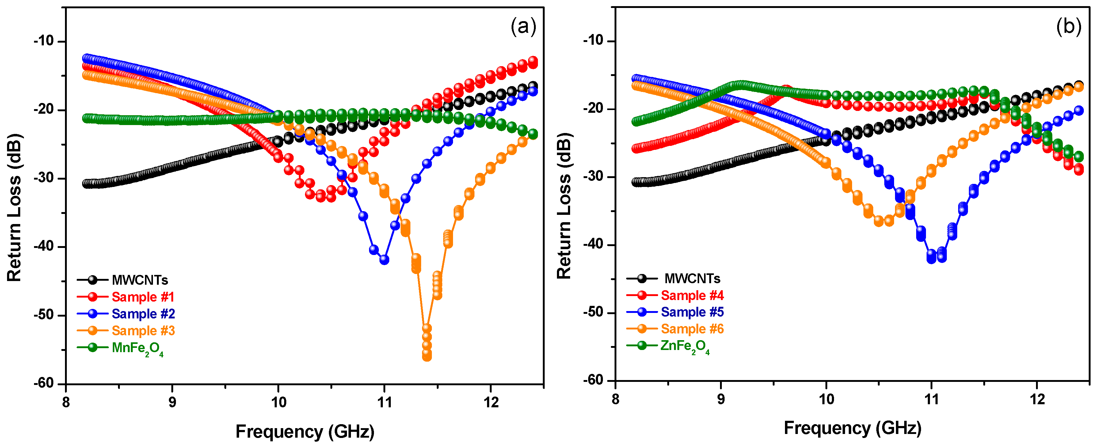
3.6. Microwave Absorption Properties

The return loss (RL) curves of the conductor-backed samples was obtained from the following equation [16,48]:
R L ( d B ) = 20 log | ( Z i n Z 0 ) ( Z i n + Z 0 ) |
Here, the effective input impedance of the sample is Zin = Z0 μ r / ε r tan h [ ( j 2 π / c ) f d μ r ε r ] , where µr and εr are the relative complex permeability and permittivity, respectively, c is the speed of light, f is the frequency, and d is the thickness of each sample.
The computed return loss (RL) for the various compositions of synthesized MZF NPs in/on MWCNTs samples of approximately the same thickness (3 mm) is shown in Figure 12. The lowest RL value and the bandwidth change with different loadings of manganese and zinc spinel ferrite nanoparticles. A minimum RL of −56 dB at 11.41 GHz with a bandwidth of 3.38 GHz (RL < −20 dB) was obtained in MWCNTs with MnFe2O4 NPs (x = 0.0). A minimum RL of −42.06 dB at 11.05 GHz with an absorption bandwidth of 3.34 GHz (RL < −20 dB) was observed in MWCNTs with ZnFe2O4 NPs (x = 1.0). These results are summarized in Table 5.
The table contains the sample codes, the center frequencies (fr), the values of minimum achievable return loss (dB), and the corresponding bandwidths (GHz). It should be noted that the dips in the values of RL versus frequency indicate low reflectivity (or a good microwave absorption). Furthermore, the minimum RL values shifted to higher frequencies and the bandwidths increased with an increasing amount of (manganese) ferrite material in the blend (Samples #1, #2, and #3 in Figure 12a). However, the minimum RL values shifted to lower frequencies with an increasing amount of (zinc) ferrite material in the blend (Samples #5 and #6 in Figure 12b). In comparison, our previous article [16] reported an RL of −38 dB with a bandwidth of 2 GHz at 16 GHz for a purely magnetic absorbing material. In addition, the results show that the dielectric (MWCNTs) materials and the magnetic materials (MZF NPs) can mutually reinforce in terms of enhancing microwave absorption properties at microwave frequencies. In order to investigate the claim that dielectric or magnetic materials by themselves have relatively low RL values, dielectric samples (only MWCNTs samples in the same wt % of total concentration of Samples #1, #2, and #3) were prepared and the values of their RL versus frequency were computed. It was observed form Figure 12a,b that dielectric or magnetic materials have low RL performance when they are used by themselves.

4. Conclusions

In this study, the synthesized Mn–Zn ferrites in/on MWCNTs with different weight ratios were investigated. All synthesized samples exhibit super-paramagnetic behavior at room temperature. XRD patterns are in good agreement with the JCPDS cards. No secondary impurity phase was detected. The absence of any additional peaks attributed to the graphite plane of MWCNTs, which indicated MWCNTs with ferrite nano-particles are relatively coated. The return loss (RL) results show that the microwave absorption properties of MWCNTs were enhanced by blending with magnetic materials. The minimum RL value shifted to higher frequencies with an increasing amount of manganese ferrite material in the blend. However, the minimum RL value tends to shift lower frequencies with an increasing amount of zinc ferrite material in the blend. The significant finding of minimum RL values indicates that the microwave absorption is about 99.99%. These results encourage further development of MWCNTs blended with ferrite nanoparticles for broadband microwave absorber applications.

Acknowledgments

Ahmet Teber is grateful to the Ministry of National Education of the Republic of Turkey (Grant number: YLSY-2009) for his graduate fellowship support. The authors, also, would like to thank Sadullah Yildirim and Lhacene Adnane for fruitful discussions.

Author Contributions

Ahmet Teber is proposed the idea, performed the microwave, XRD, and SEM experiments, analyzed/computed the return loss data and wrote the manuscript, Kadir Cil and Turgut Yilmaz performed the XRD and SEM measurements, they are also contributed to analyze the data, Busra Eraslan, Dilara Uysal and Gokce Surucu contributed to manufacturing the materials, Abdul H. Baykal contributed to synthesize the magnetic nanoparticles and contributed to analyze their magnetic properties and Rajeev Bansal contributed to review of this work.

Conflicts of Interest

The authors declare no conflict of interest.

References

  1. Rao, G.A.; Mahulikar, S.P. Integrated review of stealth technology and its role in airpower. Aeronaut. J. 2002, 106, 629–641. [Google Scholar]
  2. Barbarino, S.; Bilgen, O.; Ajaj, R.M.; Friswell, M.I.; Inman, D.J. A review of morphing aircraft. J. Intell. Mater. Syst. Struct. 2011, 22, 823–877. [Google Scholar] [CrossRef]
  3. Specialty Materials, Inc. Manufacturers of Boron and SCS Silicon Carbide Fibers and Boron Nanopowder. Available online: http://www.specmaterials.com/aerospaceapplications.htm (accessed on 12 December 2016).
  4. Wang, Z.; Wu, L.; Zhou, J.; Cai, W.; Shen, B.; Jiang, Z. Magnetite nanocrystals on multiwalled carbon nanotubes as a synergistic microwave absorber. J. Phys. Chem. C 2013, 117, 5446–5452. [Google Scholar] [CrossRef]
  5. Giannakopoulou, T.; Kompotiatis, L.; Kontogeorgakos, A.; Kordas, G. Microwave behavior of ferrites prepared via sol–gel method. J. Magn. Magn. Mater. 2002, 246, 360–365. [Google Scholar] [CrossRef]
  6. Lin, H.; Zhu, H.; Guo, H.; Yu, L. Investigation of the microwave-absorbing properties of Fe-filled carbon nanotubes. Mater. Lett. 2007, 61, 3547–3550. [Google Scholar] [CrossRef]
  7. Zou, T.; Li, H.; Zhao, N.; Shi, C. Electromagnetic and microwave absorbing properties of multi-walled carbon nanotubes filled with Ni nanowire. J. Alloy. Compd. 2010, 496, L22–L24. [Google Scholar] [CrossRef]
  8. Qing, Y.; Zhou, W.; Luo, F.; Zhu, D. Epoxy-silicone filled with multi-walled carbon nanotubes and carbonyl iron particles as a microwave absorber. Carbon 2010, 48, 4074–4080. [Google Scholar] [CrossRef]
  9. Qiu, J.; Qiu, T. Fabrication and microwave absorption properties of magnetite nanoparticle—Carbon nanotube-hollow carbon fiber composites. Carbon 2015, 81, 20–28. [Google Scholar] [CrossRef]
  10. Zhang, D.; Xu, F.; Lin, J.; Yang, Z.; Zhang, M. Electromagnetic characteristics and microwave absorption properties of carbon-encapsulated cobalt nanoparticles in 2–18-GHz frequency range. Carbon 2014, 80, 103–111. [Google Scholar] [CrossRef]
  11. Lin, H.; Zhu, H.; Guo, H.; Yu, L. Microwave-absorbing properties of Co-filled carbon nanotubes. Mater. Res. Bull. 2008, 43, 2697–2702. [Google Scholar] [CrossRef]
  12. Shi, D.; He, P.; Zhao, P.; Guo, F.F.; Wang, F.; Huth, C.; Chaud, X.; Bud’ko, S.L.; Lian, J. Magnetic alignment of Ni/Co-coated carbon nanotubes in polystyrene composites. Compos. B Eng. 2011, 42, 1532–1538. [Google Scholar] [CrossRef]
  13. Liu, G.; Wang, L.; Chen, G.; Hua, S.; Ge, C.; Zhang, H.; Wu, R. Enhanced electromagnetic absorption properties of carbon nanotubes and zinc oxide whisker microwave absorber. J. Alloy. Compd. 2012, 514, 183–188. [Google Scholar] [CrossRef]
  14. Paton, K.R.; Windle, A.H. Efficient microwave energy absorption by carbon nanotubes. Carbon 2008, 46, 1935–1941. [Google Scholar] [CrossRef]
  15. Lu, M.; Cao, W.; Shi, H.; Fang, X.; Yang, J.; Hou, Z.; Jin, H.; Wang, W.; Yuan, J.; Cao, M. Multi-wall carbon nanotubes decorated with ZnO nanocrystals: Mild solution-process synthesis and highly efficient microwave absorption properties at elevated temperature. J. Mater. Chem. A 2014, 2, 10540–10547. [Google Scholar] [CrossRef]
  16. Teber, A.; Unver, I.; Kavas, H.; Aktas, B.; Bansal, R. Knitted radar absorbing materials (RAM) based on nickel–cobalt magnetic materials. J. Magn. Magn. Mater. 2016, 406, 228–232. [Google Scholar] [CrossRef]
  17. Khan, K. Microwave Absorption Properties of Radar Absorbing Nanosized Cobalt Ferrites for High Frequency Applications. J. Supercond. Nov. Magn. 2014, 27, 453–461. [Google Scholar] [CrossRef]
  18. Sunny, V.; Kurian, P.; Mohanan, P.; Joy, P.; Anantharaman, M. A flexible microwave absorber based on nickel ferrite nanocomposite. J. Alloy. Compd. 2010, 489, 297–303. [Google Scholar] [CrossRef]
  19. Xie, J.; Han, M.; Chen, L.; Kuang, R.; Deng, L. Microwave-absorbing properties of NiCoZn spinel ferrites. J. Magn. Magn. Mater. 2007, 314, 37–42. [Google Scholar] [CrossRef]
  20. Zhao, D.; Lv, Q.; Shen, Z. Fabrication and microwave absorbing properties of Ni–Zn spinel ferrites. J. Alloys Compd. 2009, 480, 634–638. [Google Scholar] [CrossRef]
  21. Gama, A.M.; Rezende, M.C.; Dantas, C.C. Dependence of microwave absorption properties on ferrite volume fraction in MnZn ferrite/rubber radar absorbing materials. J. Magn. Magn. Mater. 2011, 323, 2782–2785. [Google Scholar] [CrossRef]
  22. Hosseini, S.H.; Asadnia, A. Synthesis, characterization, and microwave-absorbing properties of polypyrrole/MnFe2O4 nanocomposite. J. Nanomater. 2012, 2012, 3. [Google Scholar] [CrossRef]
  23. Sui, R.; Charpentier, P. Synthesis of metal oxide nanostructures by direct sol-gel chemistry in supercritical fluids. Chem. Rev. 2012, 112, 3057–3082. [Google Scholar] [CrossRef] [PubMed]
  24. Chen, L.F.; Ong, C.; Neo, C.; Varadan, V.V.; Varadan, V.K. Microwave Electronics: Measurement and Materials Characterization; John Wiley & Sons: Hoboken, NJ, USA, 2004. [Google Scholar]
  25. U.S. Research Nanomaterials, Inc. The Advanced Nanomaterials Provider. Available online: http://www.us-nano.com/inc/sdetail/228 (accessed on 12 December 2016).
  26. Debecker, D.P.; Hulea, V.; Mutin, P.H. Mesoporous mixed oxide catalysts via non-hydrolytic sol-gel: A Review. Appl. Catal. A Gen. 2013, 451, 192–206. [Google Scholar] [CrossRef]
  27. Feng, J.; Zhang, H. Hybrid materials based on lanthanide organic complexes: A review. Chem. Soc. Rev. 2013, 382, 387–410. [Google Scholar] [CrossRef] [PubMed]
  28. Demir, A.; Güner, S.; Bakis, Y.; Esir, S.; Baykal, A. Magnetic and Optical Properties of Mn1−xZnxFe2O4 Nanoparticles. J. Inorg. Organomet. Polym. Mater. 2014, 24, 729–736. [Google Scholar] [CrossRef]
  29. Agilent Literature, Agilent Basics of Measuring the Dielectric Properties of Materials, Application Note. Available online: http://cp.literature.agilent.com/litweb/pdf/5989-2589EN.pdf (accessed on 25 December 2016).
  30. Micheli, D.; Pastore, R.; Giannini, G.; Vricella, A.; Marchetti, M. Low-cost low-observable satellites made of carbon nanostructured multilayers: Numerical investigation of scattering. In Proceedings of the 53rd Israel Annual Conference on Aerospace Sciences, Tel-Aviv & Haifa, Israel, 6–7 March 2013.
  31. Micheli, D.; Apollo, C.; Gradoni, G.; Marchetti, M.; Morles, R.B.; Pastore, R. Electromagnetic Characterization of Composite Materials and Microwave Absorbing Modeling. In Advances in Nanocomposites—Synthesis, Characterization and Industrial Applications; INTECH Open Access Publisher: Rijeka, Croatia, 2011; pp. 359–384. [Google Scholar]
  32. Micheli, D.; Apollo, C.; Pastore, R.; Morles, R.B.; Laurenzi, S.; Marchetto, M. Nanostructured composite materials for electromagnetic interference shielding applications. Acta Astronaut. 2011, 69, 747–757. [Google Scholar]
  33. Fang, G.; Chen, Z.; Li, H. Synthesis and properties of microencapsulated paraffin composites with SiO2 shell as thermal energy storage materials. Chem. Eng. J. 2010, 163, 154–159. [Google Scholar] [CrossRef]
  34. Cullity, B. Elements of X-ray Diffraction; Addison-Wesely Co., Reading: Boston, MA, USA, 1978. [Google Scholar]
  35. Gozuak, F.; Koseoglu, Y.; Baykal, A.; Kavas, H. Synthesis and characterization of CoxZn1-xFe2O4 magnetic nanoparticles via a PEG-assisted route. J. Magn. Magn. Mater. 2009, 321, 2170–2177. [Google Scholar] [CrossRef]
  36. Kanade, K.; Amalnerkar, D.; Potdar, H.; Kale, B. Nanocrystalline Mn–Zn–ferrite by novel oxalato-hydrazinated complex method. Mater. Chem. Phys. 2009, 117, 187–191. [Google Scholar] [CrossRef]
  37. Apte, S.; Naik, S.; Sonawane, R.; Kale, B.; Baeg, J. Synthesis of Nanosize-Necked Structure α- and γ-Fe2O3 and its Photocatalytic Activity. J. Am. Ceram. Soc. 2007, 90, 412–414. [Google Scholar] [CrossRef]
  38. Tang, Z.X.; Sorensen, C.M.; Klabunde, K.J.; Hadjipanayis, G.C. Size-dependent Curie temperature in nanoscale MnFe2O4 particles. Phys. Rev. Lett. 1991, 67, 3602. [Google Scholar] [CrossRef] [PubMed]
  39. Brahmachari, G.; Laskar, S.; Barik, P. Magnetically separable MnFe2O4 nano-material: An efficient and reusable heterogeneous catalyst for the synthesis of 2-substituted benzimidazoles and the extended synthesis of quinoxalines at room temperature under aerobic conditions. RSC Adv. 2013, 3, 14245–14253. [Google Scholar] [CrossRef]
  40. Clark, T.M.; Evans, B. Enhanced magnetization and cation distributions in nanocrystalline ZnFe2O4: A conversion electron Mossbauer spectroscopic investigation. IEEE Trans. Magn. 1997, 33, 3745–3747. [Google Scholar] [CrossRef]
  41. Jänis, A.; Olsson, R.T.; Savage, S.; Gedde, U.W.; Klement, U. Microwave absorbing properties of ferrite-based nanocomposites. In Proceedings of Behavior and Mechanics of Multifunctional and Composite Materials (SPIE 6526), San Diego, CA, USA, 12 April 2007. [CrossRef]
  42. Kong, I.; Ahmad, S.H.; Abdullah, M.H.; Hui, D.; Yusoff, A.N.; Puryanti, D. Magnetic and microwave absorbing properties of magnetite-thermoplastic natural rubber nanocomposites. J. Magn. Magn. Mater. 2010, 322, 3401–3409. [Google Scholar] [CrossRef]
  43. Yin, Y.; Zeng, M.; Liu, J.; Tang, W.; Dong, H.; Xia, R.; Yu, R. Enhanced high-frequency absorption of anisotropic Fe3O4/graphene nanocomposites. Nat. Sci. Rep. 2016. [Google Scholar] [CrossRef] [PubMed]
  44. Zhao, H.B.; Fu, Z.B.; Chen, H.B.; Zhong, M.L.; Wang, C.Y. Excellent electromagnetic absorption capability of Ni/carbon based conductive and magnetic foams synthesized via a green one-pot route. ACS Appl. Mater. Interfaces 2016, 8, 1468–1477. [Google Scholar] [CrossRef] [PubMed]
  45. Xiang, J.; Li, J.; Zhang, X.; Ye, Q.; Xu, J.; Shen, X. Magnetic carbon nanofibers containing uniformly dispersed FE/Co/Ni nanoparticles as stable and high-performance electromagnetic wave absorbers. J. Mater. Chem. A 2014, 2, 16905–16914. [Google Scholar] [CrossRef]
  46. Liu, X.G.; Ou, Z.Q.; Geng, D.Y.; Han, Z.; Jiang, J.J.; Liu, W.; Zhang, Z.D. Influence of a graphite shell on the thermal and electromagnetic characteristics of FeNi nanoparticles. Carbon 2010, 48, 891–897. [Google Scholar] [CrossRef]
  47. Sozeri, H.; Mehmedi, Z.; Kavas, H.; Baykal, A. Magnetic and microwave properties of BaFe12O19 substituted with magnetic, non-magnetic and dielectric ions. Ceram. Int. 2015, 41, 9602–9609. [Google Scholar] [CrossRef]
  48. Naito, Y.; Suetake, K. Application of ferrite to electromagnetic wave absorber and its characteristics. IEEE Trans. Microw. Theory Tech. 1971, 19, 65–72. [Google Scholar] [CrossRef]
Figure 1. Schematic illustration of: (a) The preparation process of manganese and zinc ferrite nanoparticles (MZFs NPs); and (b) MZF NPs blended with multi-walled carbon nanotubes (MWCNTs).
Aerospace 04 00002 g001
Figure 2. Schematic illustration of the manufacturing process of the samples [30,31, 32].
Aerospace 04 00002 g002
Figure 3. XRD patterns of samples fabricated with MZF NPs by blending commercial multi-walled carbon nanotubes (MWCNTs) according to the mass fractions: (a) MWCNTs with MnFe2O4 samples; and (b) MWCNTs with ZnFe2O4 samples.
Aerospace 04 00002 g003
Figure 4. Fourier transform infrared (FT-IR) spectra of Mn1−xZnxFe2O4 NPs for (a) MnFe2O4; and (b) ZnFe2O4.
Aerospace 04 00002 g004
Figure 5. (a) Magnetic hysteresis loops of Mn1−xZnxFe2O4 NPs. The close up views for the M–H curves of (b) MnFe2O4; and (c) ZnFe2O4.
Aerospace 04 00002 g005
Figure 6. SEM micrographs of the specimens including MnFe2O4 and ZnFe2O4 blended with MWCNTs.
Aerospace 04 00002 g006
Figure 7. EDX spectrum of: (a) MnFe2O4 magnetic nanoparticles on multi-walled carbon nanotubes; and (b) ZnFe2O4 magnetic nanoparticles on multi-walled carbon nanotubes.
Aerospace 04 00002 g007
Figure 8. Schematic illustration of electromagnetic waves transmitting through and reflecting from a sample in a transmission line (such as a waveguide).
Aerospace 04 00002 g008
Figure 9. Electromagnetic constitutive parameters with (a) the real and imaginary part of permittivity for MWCNTs with MnFe2O4 samples; and (b) the real and imaginary part of permeability for MWCNTs with MnFe2O4 samples (samples are color-coded).
Aerospace 04 00002 g009aAerospace 04 00002 g009b
Figure 10. Electromagnetic constitutive parameters with (a) the real and imaginary part of permittivity for MWCNTs with ZnFe2O4 samples; (b) the real and imaginary part of permeability for MWCNTs with ZnFe2O4 samples (samples are color-coded).
Aerospace 04 00002 g010
Figure 11. The dielectric and magnetic dissipation factors with (a) MWCNTs with MnFe2O4 samples; (b) MWCNTs with ZnFe2O4 samples (samples are color-coded).
Aerospace 04 00002 g011aAerospace 04 00002 g011b
Figure 12. Frequency dependence of the return loss (RL) of MWCNTs with MZF NPs alloys; (a) MWCNTs with MnFe2O4 samples; and (b) MWCNTs with ZnFe2O4 samples.
Aerospace 04 00002 g012
Table 1. The main characteristics of the commercial multi-walled carbon nanotubes (MWCNTs) adopted as filler.
MWCNT DimensionsBulk Density (g/cm3)Specific Surface Area (m2/g)Purity (wt %)Aspect RatioManufacturing Method
Inside Diameter 5–10 nm, Outside Diameter 20–30 nm (from HRTEM, Raman), length 10–30 µm (from TEM)0.28>110 (from BET)>95 (carbon nanotubes from TGA and TEM)103Chemical Vapor Deposition (CVD)
>97 (carbon content)
Table 2. The Proportions used for the sample preparation.
Sample CodeComponents
#175 wt % (MWCNTs) with 25 wt % (MnFe2O4)
#250 wt % (MWCNTs) with 50 wt % (MnFe2O4)
#325 wt % (MWCNTs) with 75 wt % (MnFe2O4)
#475 wt % (MWCNTs) with 25 wt % (ZnFe2O4)
#550 wt % (MWCNTs) with 50 wt % (ZnFe2O4)
#625 wt % (MWCNTs) with 75 wt % (ZnFe2O4)
Table 3. Vibration frequencies of the samples.
SampleTetrahedralOctahedral
MnFe2O4433535
ZnFe2O4430528
Table 4. Magnetic properties of the synthesized specimens.
SampleMsHcMrMr/Ms
MnFe2O470.52579.720.137
ZnFe2O435.90504.030.112
Table 5. Sample codes and absorption results.
Codefr (GHz)Return Loss (dB)Bandwidth (GHz) (under −20 dB)
Sample #110.44−32.841.88 (9.42–11.3)
Sample #211.00−41.202.2 (9.84–12.04)
Sample #311.41−56.003.38 (9.7–13.08)
Sample #4---
Sample #511.05−42.063.34 (9.38–12.72)
Sample #610.55−36.722.8 (9.00–11.80)

