Design of Power, Propulsion, and Thermal Sub-Systems for a 3U CubeSat Measuring Earth’s Radiation Imbalance

1
Department of Engineering and Math, Sheffield Hallam University, Howard Street, Sheffield S1 1WB, UK
2
Department of Mechanical, Materials and Manufacturing Engineering, The University of Nottingham, University Park, Nottingham NG7 2RD, UK
*
Author to whom correspondence should be addressed.
†
These authors contributed equally to this work.
Aerospace 2018, 5(2), 63; https://doi.org/10.3390/aerospace5020063
Submission received: 22 April 2018
/
Revised: 4 June 2018
/
Accepted: 6 June 2018
/
Published: 11 June 2018
Abstract
:The paper presents the development of the power, propulsion, and thermal systems for a 3U CubeSat orbiting Earth at a radius of 600 km measuring the radiation imbalance using the RAVAN (Radiometer Assessment using Vertically Aligned NanoTubes) payload developed by NASA (National Aeronautics and Space Administration). The propulsion system was selected as a Mars-Space PPTCUP -Pulsed Plasma Thruster for CubeSat Propulsion, micro-pulsed plasma thruster with satisfactory capability to provide enough impulse to overcome the generated force due to drag to maintain an altitude of 600 km and bring the CubeSat down to a graveyard orbit of 513 km. Thermal analysis for hot case found that the integration of a black high-emissivity paint and MLI was required to prevent excessive heating within the structure. Furthermore, the power system analysis successfully defined electrical consumption scenarios for the CubeSat’s 600 km orbit. The analysis concluded that a singular 7 W solar panel mounted on a sun-facing side of the CubeSat using a sun sensor could satisfactorily power the electrical system throughout the hot phase and charge the craft’s battery enough to ensure constant electrical operation during the cold phase, even with the additional integration of an active thermal heater. However, when the inevitable end-of-life degradation of the solar cell was factored into the analysis, an approximate power deficit of 2 kJ was found. This was supplemented by additional solar cell integrated into the antenna housing face.

1. Introduction
CubeSats are classified as a form of research and commercial spacecraft, originally developed in 1999 as a collaborative project between California Polytechnic state university (CalPoly) and the space program at Stanford University [1]. The aim of the project is to standardize Nanosatellite design, reducing time and development costs. This is significantly contributing to the perpetually expanding accessibility of space exploration and experimentation. CubeSats are typically built with off-the-shelf components, readily available from specialist suppliers. CubeSats are classified by U notations referring to the maximum dimensions and allowable weights specified by the CubeSat design guide [1], specifically the 1-3U Design Specification as this paper concerns a 3U satellite.
The purpose of a CubeSat is to deliver, navigate and safely return a small payload through space to Earth. CubeSats do not independently launch into orbit. They are transported there by a launch vehicle (LV) as secondary payload. Launch vehicles are pre-scheduled flights operated by CubeSat partner companies in addition to space services and small satellite services, including Spaceflight Industries, Tyvak, NanoRacks, Innovative Solutions In Space (ISIS) and CalPoly [2]. The nanosatellites are placed within an orbital deployer which safely releases the satellites into orbit after launch. The orbital deployer also helps to ensure the safety of the vehicle by encapsulating the satellites [3].
As of 19 September 2016, a total of 479 CubeSats had been officially launched worldwide [2]. Of those launched, 210 are still operational and gathering data [2]. 70 nanosatellites were destroyed during launch [2]. A total of 40.8% of nanosatellites were launched by academic institutions, the highest of all categories [2]. This was followed by private companies in second with a total of 40.2% of all launches. Other major contributors included the military (5.3%) and space agencies (6.7%) [2]. The 3U CubeSat holds the market majority for chosen dimensions. 52.9% of all launched satellites conformed to these dimensions. The second most popular choice was the 1U configuration which had a 17.9% share of all launched types [4].
Although the first CubeSat was launched in 1999 the number of launches has grown significantly in recent years. The first major advancement in launch numbers came in 2013. The launch number for this year was 87, a huge increase on the previous year’s total of 25 [2]. This grew to around 150 per year in 2014/2015 and had peaked to 288 in 2016. There were 295 launches for 2017 [2] which highlights how rapidly this technology is advancing and the increasing rate at which it is becoming more accessible [5].
Previous experiments conducted by CubeSats include imaging of Earth’s surface, investigating the effect of lightning strikes on the outer ionosphere, deployment as an autonomous inspector to examine the host satellite and performing an experiment on E. coli bacteria in space [6]. The opportunities for research projects presented by CubeSat technology are potentially limitless. The main restriction is ensuring the experiment can be encased within the specified U dimensions and remains under the pre-agreed weight limit [1].
The power supply and propulsion system are limiting factors to the lifecycle and design of a CubeSat [3]. Due to weight limitations, it is extremely difficult to store enough energy to allow the CubeSat to operate in space for extended periods of time, often years [7]. CubeSats can utilize renewable energy sources, such as solar panels acting as a perpetual power source to ensure the device always has energy to power its electronic systems [8]. The level of control required depends on the application; however, it is difficult and expensive to utilize the energy stored in the battery to give the cube directional control. Even when this is achieved, the level of control is often very low [4]. Energy is also drawn by the experimentation payload and on-board electronics such as the altitude controller and telecommunications [9].
An isolated propulsion system can be used to direct the craft. Many technologies are currently available, ranging from tradition cold gas/chemical thrusters to Pulse Plasma thrusters [3]. These and several other systems will be evaluated throughout the course of this paper. The propulsion system is designated as a key component. It is responsible for maintaining altitude, stabilizing the craft after deployment from the OD and conducting maneuvers [4]. Conventional thrusters typically have a finite fuel supply and are actuated and controlled by the Power System. It is vital during orbit that this power system can constantly feed all electrically powered components, even during an eclipse period [10]. As the CubeSat orbits Earth it will be exposed to direct solar radiation as well as many other heating factors and be subjected to extremely low temperatures in shade as background space temperatures are typically 3 K [10]. It is vital that all CubeSat components can maintain operation throughout orbit and do not fail due to the harsh environmental conditions; this will form the base of the thermal analysis.
The development and integration of propulsion systems into CubeSats is slow and limited because standards for launch designs stipulated low-and reduced-cost launches with no harm to primary payload [11,12]. In current CubeSat specifications there is no mention of propulsion systems; however, the requirements of the design impose limitations such as pyrotechnics are not allowed on board to prevent any leakage that might compromise the primary payload launch mission [12,13]. This means chemical solid rocket propulsion systems and ignition systems are discounted and require a waiver, which will increase the time and cost of payload readiness to be launched. Limits on the chemical stored energy to 100 W-hr which is equivalent to 360 kJ significantly decrease the amount of chemical propellant on board CubeSats [12,13]. With regards to maximum allowable pressure stored, this is limited by the pressure of the storage tank, systems pressure cannot exceed 100 psig which is designated as hazardous flight hardware [12,14]. Therefore, due to the above limitation, inert gas is preferred which favored cold gas propulsion and chemical storage system limitation restricted propulsion systems applications to attitude control and reaction wheel desaturation. As of the 8 February 2017, very few CubeSats have been flown featuring propulsion systems [12]; these were mainly designated for technology demonstration. The IMPACT mission featured several electrospray thrusters from MIT, launched by the Aerospace Corporation and BricSAT-P featured four micro-Cathodes arc thrusters launched form United States Naval Academy in collaboration with George Washington University. The other CubeSats missions, less than ten [12], featured cold gas propulsion systems for attitude control and reaction wheel desaturation. More flight missions are required to validate complex propulsion systems currently under development; however, electromagnetic interferences [15] from power system units and thermal management from EP will require a solution before attempting any future flights [12,15]. Pulsed Plasma Thrusters (PPTCUP) are being developed as standalone modules that can be bolted onto CubeSat structures; this approach is becoming popular since the production of a subsystem is decoupled from the main CubeSat [16]. However, this development is mainly focused on providing translational and orbit control for CubeSat platforms. Recent studies also have addressed the limitation of onboard power by designing modular deployable solar panels [17] and solar sails [18]. To simulate dynamical situations in orbit, a testbed was developed for the solar panel deployment system and the overall performance of the system was discussed in addition to mechanical stresses acting on solar panels during deployment acceleration [17].
The current study stands out compared to previous studies, by designing a propulsion system based on pulsed plasma thruster technology and incorporating deployable solar panels with maneuvering capability using a Sun sensor to maximize solar flux collection efficiencies to enhance on-board power in addition to thermal design addressing thermal management and power requirements to carry out the mission to completion by deorbiting the CubeSat to a graveyard orbit. Previous studies were focused on the development and analysis of standalone subsystems such as propulsion system or deployable solar panels system.
2. Aims and Objectives
- Design a suitable power system for a 3U CubeSat.
- Design/specify a suitable propulsion system for a 3U CubeSat.
- Ensure Thermal Stability for all CubeSat Components throughout Orbit.
- Ensure the chosen systems can meet the mission and relevant legislation and regulations.
2.1. Power System Aims and Objectives
The objective of the craft’s power subsystem is to generate, store, control and distribute electrical energy to the craft’s sub-systems [3]. Typically, the propulsion system, Altitude Determination and Control System, Payload, Communication system and On-Board Computer will all require an electrical power source to operate for conventional designs [7]. It is necessary to specify the amount of power generated throughout the CubeSat’s orbit, the consumption of the craft’s systems, maximum storage capacity and other key electrical equipment such as DC to DC converters to step down supplied voltage incoming power from the solar cells. The power system is critical to the mission’s success as the craft cannot operate without a suitable power supply [3].
Power System Objectives
- Research suitable propulsion systems for a 3U CubeSat gathering performance data and operational complexity data.
- Research existing Power systems used for previous missions.
- Identify, select/design and analyze means of power generation, storage, control, and distribution.
- Verify the selected system can provide power to the fed subsystems throughout orbit.
- Create an electrical layout, noting mass, volume, performance, and cost of each component.
2.2. Propulsion System Aims and Objectives
The propulsion systems role is to maintain the craft’s orbiting altitude, as well as allowing it to perform orbital maneuvers and reach a safe graveyard orbit once the mission is complete [19]. This report will research previously incorporated propulsion systems as well as analyzing readily available off-the-shelf systems. Suitable technologies will be compared and selected using engineering design tools as a justification based on performance data from manufacturers. The chosen systems operation will be analyzed in mathematical detail. The mass, volume, power and fuel consumption and cost will all be considered during selection.
Propulsion System Objectives
- Research suitable propulsion systems for a 3U CubeSat gathering performance data and operational complexity data.
- Analyze the researched systems, using Engineering Design tools to specify baseline requirements based on the missions needs and applicable safety regulations.
- Select a suitable propulsion system to power the craft, then further select an off-the-shelf component incorporating this technology.
- Verify the suitability of the chosen system, ensuring it can meet the mission and safety requirements.
- Ensure achievable power consumption from the electrical system throughout the orbit cycle.
2.3. Thermal System Aims and Objectives
The thermal system is designed to ensure temperatures throughout the structure do not reach extremes which are greater than the operating ranges of the selected components [10]. This will ensure safe operation of the CubeSat and help minimize the risk of mission failure. Throughout its orbit the CubeSat will absorb large amounts of incident radiation, especially when exposed to direct solar radiation from sunlight [20]. This exposure will cause heating of the CubeSat therefore material selection is vital to minimize this heating effect. The background temperature of space is approximately 3 K. When in an area of eclipse this extremely low temperature is below the operating range of many of the components, particularly batteries which can only survive around 5 °C typically [21]. It may be necessary to incorporate a method of cooling and insulating components, to prevent these extreme temperatures affecting operation. Material consideration should also be taken into account, especially regarding the emissivity and absorptivity of the outer materials which act as a thermal interface with the incoming radiation [10].
Thermal System Objectives
- Research existing thermal management systems and material selections for successful CubeSat flights.
- Investigate heat dissipation of internal electrical components and its impact upon the thermal system.
- Quantify the incoming radiation incident to the CubeSat and corresponding maximum and minimum temperatures.
- Develop thermal load cases for various configurations, identifying advantages and disadvantages.
- Calculate the time period of orbit around Earth at 600 km and the time spent in eclipse.
2.4. Mission Statement and Payload
The developed sub-systems will power a 3U CubeSat, with an experimental payload capable of measuring Earth’s radiation imbalance using Vertically Aligned Nanotubes as a Radiometer assessment, commonly referred to as RAVAN by NASA. Measuring Earth’s radiation imbalance is key to predicting climate change for the coming decades [9], data generated by the mission will be vital in influencing the reduction of pollution from manmade sources and helping Engineers/Geographers prepare for the warming effects potential impacts.
The phenomenon of climate change is due to change in Earth’s energy budget. This is a delicate balance between incoming solar energy entering Earth’s atmosphere and opposing reflected solar and thermal radiation leaving the atmosphere [22]. A negative balance would have a cooling effect on the world’s climate whereas a positive budget would cause energy accumulation raising the temperature within the atmosphere, a trend which is widely accepted by society. It is currently estimated that Earth’s radiation imbalance is around 1 W/m2 causing the warming effect [22]. This value is attained mainly using satellite observations and tracking ocean temperature values. It is also widely accepted that imbalance is driven by increased greenhouse gas emissions from human sources [9].
The value of incoming solar radiation is relatively stable, estimated at an average integrated value over the atmosphere of 340.20 ± 0.12 W/m2 [22]. The purpose of this experiment is therefore to measure the total outgoing radiation (TOR), this value alters significantly at different global regions. Recent satellite observations globally and mathematical models state the energy radiation imbalance can range from −2 to −7 W/m2, showing a large variation to the estimated value of 1 W/m2. The satellite equipment used to measure values of TOR is outdated and inaccurate. Recently developed RAVAN technology for nanosatellites can measure TOR to an accuracy of 0.5 W/m2 providing a much more accurate estimation of globally altering TOR values [9]. This data is pivotal to tackling and monitoring the issue of global warming and acts as significant justification for the launch of this CubeSat. Ideally a constellation of nanosatellites orbiting Earth would build up an accurate global network of real time data for TOR values as shown in Figure 1. A constellation of satellite would be of huge expense; it is, therefore, required that the selected propulsion system is widely available and cost effective as estimates suggest at least 40 satellites would be needed.
The CubeSat’s orbit will be a near circular Sun-synchronous low Earth orbit at an altitude of 600 km, with an inclination of 98 degrees [9].
The RAVAN system measures Earth-leaving fluxes and incoming solar radiation mainly from the Sun’s rays using two technologies. It utilizes vertically aligned Carbon nanotubes (VACNTs) to create a radiometer absorber. Carbon nanotubes have one of the lowest spectral responses over an extensive wavelength range known to man. This is combined with a gallium black body. This acts as a calibration device for the sensor [9].
Carbon Nanotubes are hollow cylinders constructed of graphene. When aligned in a forest configuration (See Figure 2) they become one of the blackest structures available to engineers. A forest is mostly an empty hollow space, acting as a photon trap. With regards to space exploration, they are compact, mechanically able to withstand stresses and do not produce gas meeting CubeSat specification launch requirements.
The second significant component of the experimental payload is the Gallium black body calibrator. Two gallium bodies are attached to sensor head contamination covers (see Figure 3). These bodies are infra-red sources used in conjunction with deep space looks to determine a constant reference calibration value. Gallium is a stable and non-toxic material, once again meeting the CubeSat regulations and posing no risk to humans.
2.5. Environmental Conditions at 600 km Altitude
At an altitude of 600 km the satellite is orbiting around the upper limit of Earth’s thermosphere. This region of the thermosphere is at a relatively low altitude [20] compared to the orbiting altitude of larger medium Earth orbit and geostationary orbit craft which operate at around 20,000 km and 36,000 km respectively [23].
The MSISE-90 model of Earth’s upper atmosphere gives the following properties of air at an altitude of 600 km: See Table 2.
The following values (Table 3) apply to air at a 600 km altitude relative to sea level; with mean solar activity rather than low solar activity, and will be used from this point forwards to give a fair representation of the conditions the CubeSat will encounter. At this altitude, solar activity has a significant impact upon the relative small amount of oxygen due to the intense amount of solar radiation [3]. This altitude is above the “Karman Line” meaning astronautics should be applied instead of aeronautics. The upper thermosphere is too thin to support conventional aircraft and vehicles must travel at orbital velocities [7].
3. Background
The CubeSat program is designed to standardize and reduce development costs of nanosatellites, as well as ensuring the safety of the launch vehicle. This is done with the aim of improving the accessibility of space exploration for a range of organizations including academic institutions, governmental divisions, and the corporate sector through education and by establishing a baseline specification. The 3U CubeSat has nominal dimensions of 100 mm by 100 mm by 340.5 mm [1]. Figure 4 illustrates 1U and 3U CubeSat developed by CalPoly. Pre-Assembled flight-ready structures are available at a premium from specialist suppliers; however, the design specification developed by CalPoly is designed to help those looking to construct a CubeSat independently. Upon launch the CubeSats are loaded into a Poly Picosatellite Orbital Deployer (P-POD) [1]. The requirements for insertion into the P-POD are also specified in the design guide. Only one 3U CubeSat may be loaded into the P-POD at a time, any larger craft than a 3U would require the development and approval of a custom fabricated deployer.
3.1. General CubeSat Specifications
The CubeSat design specification states the requirements and regulations a designed CubeSat must meet before consent to fly is granted. The document is separated into general, mechanical, operational, and electrical design segments. The mechanical segment largely details the CubeSat structure and that of the P-POD, particularly the P-POD rails upon which the CubeSat is mounted throughout the launch and slides along upon release. The waiver process for design alteration is presented for deviations from the specified baseline [1]. The design guide, along with the GEVS documentation state the following tests are required before launch acceptance [24]:
- Random Vibration;
- Thermal Vacuum Bake-out;
- Visual Inspection Qualification;
- Acoustic Test;
- Sine Vibration;
- Mechanical Shock;
- Mechanical Functional Analysis and Test.
3.1.1. Power Sub-System Specifications
The CubeSat Design specification complied by California State Polytechnic university is sparse in detail with regards to the power sub-system. The document does however state that the proposed CubeSat must be able to conduct a “dead launch”, stating that all electronic sub-systems and components remain dormant during the deployment phase upon release from the P-POD [1]. All batteries must be either disconnected or fully discharged throughout the dead launch phase. The CubeSat must also incorporate a “remove before flight” pin to prevent accidental activation of any of the electrical systems during any conducted ground tests [1].
CubeSat powered function include the variety of subsystems such as command and data handling (C&DH), RF communication, Altitude determination and control (ADC) and deployable mechanism actuation. CubeSat power systems include all battery assemblies, solar cells, and coin cell batteries. CubeSats will incorporate battery circuit protection for charging/discharging to avoid unbalanced cell conditions. The CubeSat will have one RF inhibit and RF power output of no greater than 1.5 W at the transmitting antenna’s RF input [1].
3.1.2. Propulsion System Specifications
Many propulsion systems, such as cold gas and pulsed plasma thrusters, will require a fuel storage vessel to securely transport propellant. Any vessel on board a CubeSat is restricted to a maximum pressure of 0.12159 MPa (1.2 atm) [1] and must incorporate a minimum safety factor of 4 for the vessel. This restriction has a detrimental effect on thrusters which require pressure differential potential energy to generate thrust and specific impulse to maneuver and maintain altitude.
The incorporation of pyrotechnics into any aspect of CubeSat design is also strictly prohibited [1]. Typically, pyrotechnics are used as an igniter for chemical propulsion systems and a propellant isolator in pyrotechnic valves for propulsion systems. Any propulsion systems will be designed integrated and tested in accordance with AFSPCMAN 91-710 volume 3 and will have at least 3 Inhibits to activation [1]. Total stored chemical energy will not exceed 100 W-hr and any hazardous materials incorporated into the design, for example propellant, will also conform to AFSPCMAN 91-710, Volume 3.
3.1.3. Thermal/Material Selection Specifications
No direct consideration is paid directly to the design of the thermal system, as this will differ depending on each individual CubeSat’s requirement i.e., orbit type, altitude, electrical system, and material selection. Restrictions are however placed upon material selection. CubeSat material outgassing should conform to NASA outgassing standards [24]. CubeSat materials will have a total mass loss (TML) less than or equal to 1% and CubeSat materials will have a collected volatile condensable material (CVCM) equal to or less than 0.1% [1]. All parts will remain attached to the CubeSats during launch, ejection, and operation. No space debris will be created [1]. Typically, Insulation (MLI) and surface coatings to reflect/absorb incoming solar radiation are used as simplistic thermal management systems for craft. However, systems such as passive louvers, non-metallic thermal straps, cryo-coolers, and sunshades are under development for CubeSat platforms [23].
3.1.4. Mechanical and P-POD Specification
The CalPoly design specification presents many regulations regarding the CubeSat structure, mainly to ensure compatibility with the P-POD structure. The engineering drawing detailing 3U CubeSat component definition gives the following dimensions [1]: (Table 4).
Only the CubeSat rails are permitted to contact the P-POD [1]. This will have a significant impact upon design as components such as communication antenna and deployable solar booms will require a compact release mechanism until deployment is complete. As a 3U CubeSat is placed inside the P-POD alone, separation springs are not required [1]. To prevent cold welding between the CubeSat and P-POD surfaces the satellites primary structure must be constructed from hard anodized Aluminum 7075 or 6061. The center of gravity will be located within 45 mm from its geometric center in respect to the Z direction [1].
Operators will obtain and provide documentation of proper licenses for use of radio frequencies. CubeSats will comply with their countries radio license agreements and restrictions [1]. CubeSat’s mission design and hardware will be in accordance with NPR 8715.6 to limit orbital debris. Any CubeSat component will re-enter with energy less than 15 J. All deployable devices such as booms, antennas and solar panels will wait to deploy a minimum of 30 min after the CubeSat’s deployment switches are activated from orbital deployer ejection [1]. No CubeSat will generate or transmit any signal from the time of integration into the orbital deployer through 45 min after on-orbit deployment. However, the CubeSat can be powered on following deployment. Figure 5 illustrates the POD exterior courtesy of [1].
For a CubeSat to be loaded into a P-POD for flight, it must firstly pass a rigorous testing procedure. Depending on the private launch provider additional testing may be required [1]. If the launch provider is unknown the GSFC-STD-7000 NASA Godard Space Flight Centre standard may be used as a testing baseline [24]. The qualification testing is designed to test both prototype and proto-flight hardware. It is the responsibility of the CubeSat developer to arrange/conduct testing.
The orbital deployer referred to as the PPOD by CalPoly is a standardized device with the purpose of carrying and ejecting the CubeSat(s) from the launch vehicle safely. It is a rectangular box with spring mechanism powered door. An electronic signal is sent from the launch vehicle to the deployers release mechanism actuator triggering torsion springs to open the release door. The stored CubeSats then slide along rails (specified in the design guide) out of the deployer and into orbit. Rails will have a surface roughness less than 1.6 µm and the edges of the rails will be rounded to a radius of at least 1 mm [1].
3.1.5. GEVS and QB50 Testing Standard Considerations
The QB50 project is a network of 50 CubeSats with 2 or 3U dimensions with the purpose of long duration exploration of Earth’s lower thermosphere (200–380 km) for re-entry research and in-orbit demonstration of technologies and miniaturized sensors. The QB50 project database provides a detailed methodology and range of acceptance criteria for vibrational testing, while the GEVS documentation provides analysis of all other required testing methods [25].
3.2. Power Sub-System Overview
The electrical power sub-system is required to manage, store, and generate electrical energy and distribute this to consuming components and sub-systems [23]. Typically, the electrical power system will account for approximately a third of the total space-craft mass. Commonly used power generation sources include Photovoltaic Cells, solar arrays, and thermonuclear power generators, although these are commonly found on much larger craft [23].
Power storage is typically performed by rechargeable lithium-ion batteries; close attention should be paid to this component during thermal design [26]. A power management and distribution module (PMAD), often referred to as a battery management system is employed to control the control of power draw to the instrumentation and sub systems. This device is often engineered to meet specific mission requirements; however, off-the-shelf components are readily available [21]. As a CubeSat is constrained by weight and volume it is vital to select components with a high specific power to mass ratio [23]. Figure 6 illustrates a simplistic overview of a CubeSat Power subsystem.
3.2.1. Power Generation
Solar cells typically act as the electrical power generation source for CubeSats as they can use the photovoltaic effect to harness the perpetual energy of the incoming solar radiation incident upon the craft [21]. This provides a renewable source of energy for the craft extending the mission lifecycle, compared to utilizing a finite source [23]. Photovoltaic cells are constructed from extremely thin semi-conductor wafers which generate an electrical current when exposed to incoming light [28]. The amount of incoming light depends on the distance of the craft’s orbit from the Sun as the intensity varies per the inverse square law, and the projected surface area of panel exposed to the Sun as this varies throughout orbit depending on the cosine angle of the panel with respect to the Suns absolute position.
A large market share of available PV cell products employs single junction cells; however, the efficiency of these products is approximately 20%, which is a relatively low value compared to multi-junction cells [23]. The multi-junction incorporates multiple layers of materials with altering band gaps, allowing the utilization of a wider spectrum of solar radiation. In the aerospace industry triple junction cells are commonly used due to their ideal efficiency to cost ratio. The significant downfall of solar cells is that they have a high mass and surface area, are unable to generate power in the CubeSat’s eclipse period of orbit, have high initial cost, and degrade over time [23]. Figure 7 highlight typical solar cell efficiencies of various manufacturers.
Solar cells are typically constructed from semiconductors including Silicon (Si) and Gallium Arsenide (GaAs) [3]. Solar arrays are readily available off the shelf from a range of large providers including ISIS and Clyde Space.
Many cutting-edge energy sources are under development for space applications including hydrogen fuel cells, thermo-voltaic batteries, and flexible solar cell films [23].
3.2.2. Power Storage
The CubeSat design guide does not permit batteries to be charged upon launch, they must be fully discharged and only activate 30 min after release from the P-POD [1]. Therefore “Primary” pre-charged batteries typically used over short mission durations are not permitted for this design. Secondary rechargeable batteries therefore must be utilized, fed by the power generation source which is usually a solar cell. Secondary batteries are commonly made using Nickel-Cadmium (NiCad), Nickel-Hydrogen (NiH2), Lithium Iron (Li-ion) and Lithium Polymer (Li-Po) [23]. The type of battery selected depends upon the application. Criteria such as energy density, life cycle, reliability, and cost must all be considered. Figure 8 shows power energy densities of various battery types.
Typically, batteries with a high energy density would be selected, as they are able to store a large capacity per unit mass; however, this incurs an ever-increasing build cost causing selection to be influenced by available budget. Lithium Iron and Lithium Polymer represent cutting-edge technologies in the field of energy storage [23] and are constantly under development, recently used in hybrid/solar powered vehicles on Earth. Figure 9 provides off-the-shelf comparison of battery cell energy densities of various products.
Typically, secondary batteries are unable to power all operational CubeSat components during the eclipse phase of orbit. Many non-critical components will enter a low power period during this phase. If a design alteration is permitted, some CubeSat designs have incorporated primary batteries to release solar panels booms for example, to allow the secondary batteries to begin storing electrical energy [3].
3.2.3. Power Management and Distribution (PMAD)
The power management and distribution system is often custom designed based on the mission objective, this however is an extremely expensive development process, typically only utilized by large organizations such as Space X and NASA with healthy budgets. Many CubeSat developers are smaller organization with smaller budgets such as universities and small corporations. These companies rely on off-the-shelf components (Figure 10) developed by a range of businesses including ISIS, Clyde Space and Pumpkin. Typically, standardized PMAD components have a main battery bus voltage of 8.2 V, with the ability to distribute regulated 5 V and 3.3 V supplies [23]. The PMAD possess the ability to manage the battery, control capacitor charging/discharging and condition and amplify the voltage signal [3].
The PMAD is a vital piece of equipment currently installed in every CubeSat launched into orbit [2]. The balance of power generation, storage, and consumption on board a CubeSat is very delicate; therefore, it is vital a suitable PMAD is selected. Every PMAD possesses junctions to transfer power from the generation source, a power conditioner, and a switching circuit to divert power to systems/instrumentation. The component is usually connected to a universal bus. PMADs are beginning to be developed with the ability to only divert power from the battery once the solar panels are no longer able to supply adequate power, preserving the electrical energy reserve for the eclipse period and the ability to “dead switch” [1,3].
When the standard voltage supply from the battery is insufficient, a capacitor is typically incorporated to provide a burst of electrical energy, usually to power the payload in applications such as high-resolution imaging [3]. High-end systems can relay operational power system data back to ground control and command the inclination of the craft to maximize incident solar radiation to the Photovoltaic cells. Stras space manufacture a power converter with a voltage input range between 3.3–40 V with an efficiency of 90% [23].
3.3. Propulsion System Technologies Overview
A wide range of propulsion systems are available as off-the-shelf components, many of which have been adapted and miniaturized from existing larger scale satellite and rocket technologies. Typically, cold gas thrusters are selected as propulsion systems for CubeSats [23]; however, many developments have been made in this field due, in part to the increased popularity of the CubeSat program which can perform more complex maneuvers and provide higher values of specific impulse, for example pulsed plasma thrusters. Typically, thrusters are installed in larger bus satellites, but further miniaturization allows propulsion systems now to be considered for small craft such as 3U CubeSats [23]. Solutions such as Pulsed Plasma Thrusters and electrosprays are favored for CubeSats, as they are compact, easy to install and have a low degree of complexity. Technologies such as solar sails and Hall Effect thrusters which can provide increased range and increases in velocity for CubeSats are still under development. The advances of the solar sail are particularly of interest to the scientific world, as they could increase the duration of CubeSat mission indefinitely as solar radiation is perpetual power source in the realms of our solar system [8].
CubeSats do not launch themselves. The P-POD carries the CubeSat outside Earth’s atmosphere and into orbit. Once released into space the launch vehicle no longer controls them [1]. They are therefore required to be able to navigate self-sufficiently and maintain altitude. A CubeSat may also be required to have precise directional control depending on the satellites purpose [3]. For example, CubeSats are often deployed as inspectors for larger Satellites and are required to precisely navigate to allow the optimum angle for the integrated optics.
3.3.1. Chemical Propulsion Systems
As chemical compounds store high densities of energy, they are ideal for small craft such as CubeSats as they can provide large amounts of energy in a compact volume. Chemical propulsion systems are desirable as they can satisfy high thrust impulsive maneuvers [23]. Typically, chemical propulsion systems have lower specific impulse outputs compared to electric equivalents but have greater thrust to power ratios, making them suitable for larger craft with higher masses. Table 5 illustrates propulsion systems for small spacecraft.
This system generates a chemical reaction to generate a high-pressure gas. This gas is then channeled through a nozzle to produce a reaction force and propel the satellite forwards. The gas exhaust temperature is usually high, and the reactant could potentially be in a liquid or gas state [23]. Previously, a mixture of liquid and gas has been used to produce a chemical reaction. A monopropellant is often used in cold gas thrusters. This process uses a single propellant to produce a reaction when passed over a catalyst. Alternatively, a bipropellant can be used, this is the reaction of an oxidizer and a fuel [3].
Monopropellant systems are commonly used to power CubeSat systems. They provide a high thrust output (Propellant-dependent) while maintaining a low complexity. This system has a low electrical power requirement and a very high reliability. Monopropellant thrusters are often utilized for orbit raising. The alternative bipropellant system offers better performance for this purpose as it produces more thrust giving more directional control; however, the system is much more complex than a mono as it has a complex feed system and occupies a larger volume [23].
With current technology, solid rocket motors are not suitable for nanosatellites. Even the smallest systems would exceed the weight and volume limits set for a CubeSat. Monopropellant systems are often powered by passing hydrazine over a catalyst. They can comfortably meet the specific impulse and volume requirements of a CubeSat. However, this power system requires a much higher power source than the allowed 1 W to actuate the thruster valve [30]. The hydrazine would also require heating to prevent it freezing once in orbit. This thermal regulation cannot be accommodated by the limited CubeSat power supply. Several Hydrazine blends have been developed which have far lower freezing points, meaning constant heating is no longer required. However, the power required to actuate the valve is still an existing issue [31].
For altitude control, thrusters often operate in pulse mode (Figure 11), delivering regular bursts of impulse. The amount of impulse needed depends on the rate of spin around the precession spin axis. It is desirable to be able to control this rate of spin. A cold gas thruster and Hydrazine monopropellant would be suitable for delivering short, accurate pulses [3]. Liquid monopropellant systems can provide significantly larger burst of impulse compared to the gas alternatives. It is extremely viable to state that a mono system could be used for both altitude control and orbit raising. The only limiting factors are volume and power supply for valve actuation [23].
Hydrazine Propellant propulsion systems are typically integrated into large craft, as they represent a reliable power source. The hydrazine system utilizes a double stage flow control valve to regulate propellant supply, which is fed to a catalyst heater surrounded by insulation. An advantage of incorporating Hydrazine thrusters is the ability to perform multiple cold starts, which is useful for power critical short CubeSat missions. Available systems on the market include CHAMPS (CubeSat High-Impulse Adaptable Modular Propulsion System) [32]. See Figure 12 and Figure 13.
The cold gas system (Figure 14) uses an inert gas stored at pressure to produce thrust. Nitrogen is the most commonly used inert gas. As space is a vacuum there is a significant pressure difference between the stored gas and the release environment. A valve is opened releasing the gas, this is directed through a nozzle to provide directional control [3]. The pressure difference generates a reaction force upon the CubeSat propelling it through space. As the system is controlled by a single valve it is an extremely simple system with low mechanical complexity. The inert gases such as nitrogen are not intrinsically corrosive or dangerous which meets the safety requirements set by the CubeSat design guide [1]. It also reduces risk to the launch vehicle and orbital deployer.
The main disadvantage of cold gas thrusters is that they provide a very low level of performance compared to other propulsion systems [19]. Even at high pressures, the release of the inert gas only produces a very small amount of impulse upon the CubeSat, meaning low maneuverability and acceleration even for low-mass nanosatellites. This factor alone means cold gas thrusters are commonly used for CubeSats [2]. The maximum theoretical specific impulse for a nitrogen cold gas thruster in a vacuum is 76 s. Another issue with cold gas thrusters is that commonly used gases such as nitrogen have low densities. Due to the fact volume is limited; this is an important issue as gas supplies are rapidly consumed vastly limiting the operational time of the satellite. Technology is currently under development by NASA to allow solid fuel to be the primary source, which is then combusted in a plenum to produce the desired gaseous output. This allows a much larger quantity of gas to be carried within the same volume extending the operational life of the satellite [23].
Cold gas thrusters represent the most mature propulsion technology for CubeSats but however provide limited spacecraft propulsion capabilities, advanced system use highly pressurized gas, with a vessel pressure greater than that allowed by the CubeSat design guide [1]. As the technology has developed over time, warm gas thrusters have been selected by developers and integrated to orbiting designs [23]. The basic operation of a warm gas thruster is identical to that of a cold, providing a higher value of specific impulse [33]. Table 7 illustrates cold and warm gas propulsion systems performance and the stage of the development status from various manufacturers.
The CPOD system manufactured by VACCO represents a plausible propulsion system solution for the mission. It has 1U dimensions, is center mounted, has a nominal thrust of 25 mN and a total impulse of 186 N-s [34].
Non-toxic propellants (Table 8) represent are classed as “green fuels” due to their reduced toxicity which help meets the CubeSat requirements [1]. Compared to Hydrazine they have a reduced vapor pressure, making them a safer alternative. Non-toxics are still in the development phase, but are expected to provide higher performance than current market-leading state-of-the-art fuels.
The HYDROS system shown in Figure 15 represents a water electrolysis propulsion system, electrolyzing water into hydrogen and oxygen to produce a bi-propellant thruster. It has a modular nozzle and injector design allow it to be manufactured to any CubeSat size specification [35].
The use of solid rocket motors to power nanosatellites is rare; however, NASA did attempt to develop a suitable system that could accommodate the weight, power, and volume restrictions of a nanosatellite. It was developed in conjunction with Thiokol Corporation for the MagCon mission. A special casing was developed bringing the entire systems weight down to 0.4 kg. This miniaturized motor could develop 20 ms of impulse in a vacuum with a power supply of 3.3 V of direct current. In comparison, a motor with a much larger 150 mm tank diameter can deliver 100 N-s of total impulse in the same conditions. The mass of this system is 1.25 kg (almost an entire 1.38 kg U) compared to the miniatures 0.4 kg weight [2,31].
When a solid fuel mixture is combusted, several factors affect the impulse produced by the high-pressure high-temperature exhaust gases. The amount of torque produced depends on the area of the flame front. The gases are then passed through a nozzle to accelerate the flow [30]. The reaction force produced can be calculated by Newton’s third law of motion. The nozzle affects the torque produced. The throat of the nozzle (smallest cross-sectional area) will determine the Mach number of the flow which can then be substituted into a version of the general thrust equation, see Figure 16 [30].
Solid rocket motors for nanosatellites are not widely used and are extremely expensive. They provide a very viable option theoretically; however, factors such as price, availability, and suppliers reduce their viability [3].
Typically, Solid rocket technology is implemented into designs upon which impulse maneuvers such as insertion and de-orbiting are required. The solid propellant achieves moderate specific impulses and high thrust magnitudes making it suited to larger buses, rather than smaller CubeSats (Table 9). A thrust vector control system is usually integrated to allow larger changes in velocity than an uncontrolled system [23].
3.3.2. Electrical Propulsion Systems
Although CubeSat technology is still developing as interest and investment rises significant improvement in the field of Electric propulsion has occurred. Small CubeSat craft require high values of specific impulse which electrical systems can provide; however, this comes at the cost of low thrust output meaning maneuvers take an extended period of time. Given that the system’s main requirement is to maintain the altitude of the craft, and it is not required to complete complex maneuvers—for example orbital positioning for imaging—it would be suited to an electrical propulsion system which can provide a long lifespan with low specific fuel consumption. The thruster is required to perform small correction and altitude control maneuvers rather than interplanetary spiral trajectories [23]. A well-suited system would be a Pulsed Plasma Thruster/Electrospray using polytetrafluoroethylene.
The most basic form of electric propulsion system is a Resistojet. The system works by a heating mechanism, combusting the propellant electrically to create a gas which expands and is expelled at a high velocity propelling the craft in a desired direction [3]. As the heating process increasing the exit velocity compared to a purely pressurized release, it has a greater “fuel efficiency” as it can generate more thrust per unit fuel, as the heating is usually powered by energy generated from the solar cells [15]. Collaboration between CU aerospace and VACCO has produced a CubeSat compatible Resistojet propulsion system targeted at 2U to 6U buses.
Busek [36] have development an Ammonia Micro-Resistojet system incorporating a rocket nozzle. Table 10 demonstrates Busek Ammonia Micro-Resistojet performance.
An electrospray would serve as an extremely viable solution (see Table 11 and Figure 17) to this mission requirement, due to its low fuel consumption and strong performance. An electrospray system operates upon the phenomenon of electrostatic extraction and acceleration of ions from a given propellant from a vapor pressure conductive salt. No gas-phase ionization is required which serves a major advantage of this design [23]. There is also no need to store pressurized propellant which is advantageous due to limited space and the maximum pressure vessel regulation of 1.2 atm [1]. The most commonly used propellant is an ionic liquid (1-ethy1-3-methyl-imadazolium tetra fluoroborate).
Ion propulsion systems have been deemed outside of this projects scope, this is due to their significant power consumption of at least 10 W [15]. The BIT 1, 2 and 3 models supplied by Busek have respective power consumptions of 28 W, 75 W and 460 W [36].
A pulsed plasma thruster produces thrust by generating a high-voltage discharge between two separate electrodes, leading to an electric arc formation which ablates a solid material [23]. The thruster generates a magnetic field which accelerates the particle from the thruster nozzle. The magnetic field is often shielded using a Faraday guard to prevent magnetic interference to components such as the altitude determination and control system for example. The propellant is usually fed into the arc by an actuating spring; Figure 18 illustrates a typical Phase Four thruster [38]. Pulsed Plasma thrusters were derived from larger scale space craft applications. Pulsed Plasma Thrusters are suited to altitude control and fine pointing which meets the mission requirements; this is because the pulse impulse magnitude is adjustable [38].
Pulse control is usually achieved by electronically controlling the discharge rate of the capacitor operating the thruster using a PPU. The Lorentz force created due to the magnetic field and electric current is quantified using:
F is equal to the force, q is the electric charge, v is the velocity of the charge and B is the strength of the magnetic field (Tesla’s) [39]. A Pulsed plasma thruster design is illustrated in Figure 19. Failure in this thruster often occurs due to electrode surface charring, limited total impulse due to fuel consumption and pulsed thruster instead of continuous discharge [4].
Below (Table 12) are typical Pulsed Plasma and Vacuum Arc propulsion system performance values:
The P4 RFT (Phase Four Company) shown in Figure 20 is of particular interest to this project. It is a “CubeSat Ampibolar Thruster” (CAT) developed by the university of Michigan and exclusively licensed for production [37]. It utilizes a magnetic helicon discharge when ionizing the chosen propellant [23]. This system eliminates the need for a separate electron source and produces no magnetic dipole. The device generates plasma using helicon radio frequency source. As the system is electrodeless, a vast range of propellants may be employed, including water [4]; however, iodine is emerging as the most popular selection due to low cost and high energy density [23]. Iodine operating P4 RFT systems have achieved specific impulse values of 1010 s.
Hall effect thrusters (Figure 21) are another example of mature technology which has undergone miniaturization to make it a viable nanosatellite technology. The miniaturization of components such as neutralizers is still ongoing; therefore, overall power consumption is very high [23] compared to viable alternatives such as pulsed plasma thrusters and electrojets.
The Busek 200 (Figure 22) however is aimed at much larger CubeSats with increased electrical capacity. Power consumption of this component ranges between 100–300 W [35]. Miniaturized Hall effect thrusters are under development by the University of Toronto’s Space flight Laboratory (Figure 22) to consume sub 200 W values, but these thrusters are still far too electrically demanding for the current capabilities of a 3U CubeSat.
3.3.3. Propellant-Less Propulsion Systems
Systems designated Propellant-less do not carry propellant. They are ideal as this reduces mass and complexity. They are ideal long-distance missions to other solar systems and planets, as they rely on perpetual fuel supply such as solar radiation and the main limiting factor is component life span. A notable application of propellant-less technology is the LightSail-A mission. A solar sail was employed as the craft’s propulsion system with a total area of 32 m2. The craft orbited at 720 km and could perform altitude regulation and alteration (Figure 23) [8].
Solar Sails are the most commonly employed form of propellant-less propulsion system on board CubeSats [23]. Incoming solar radiation packed with photons, is reflected by the sails highly reflective film material generating a pressure, propelling the craft forwards [23]. The incoming photons rate of change of momentum during reflection exerts an equal and opposite force upon the craft’s sail. This momentum is of an extremely small magnitude; typically sails for small buses (2–6U) are around 32 m2 [8]. Unlike chemical thrusters, the incoming radiation is constant allowing a gradual gain of momentum over time. This allows craft to reach high speeds, making this a viable option for interplanetary travel [8]. Figure 24 illustrates the dimensions of stowed versus deployed solar sail configuration [40].
3.4. Thermal System Overview
All components inserted into the CubeSat design have a range of operating temperatures, and a survival range, which if exceeded, will cause failure of the component. It is, therefore, vital the temperature throughout the CubeSat is managed using a range of thermal devices.
A passive thermal control system is defined as one which does not require power input from the electrical system. Passive systems are typically low cost, risk, weight, and volume with high reliability [7]. Passive systems usually comprise of Multi-Layered Insulation and specially developed surface coatings manufactured by companies such as 3 M, and occasionally additional systems including heat pipes and sunshades [23]. MLI and thermal coatings have been integrated upon many notable CubeSat craft including COMPASS-1 and PICARD [2].
Thermal insulation is incorporated into CubeSat design to block incoming solar radiation, and to prevent excessive heat dissipation. It is commonly applied to maintain a set temperature range for on-board electronic equipment during orbit. The commonest form of thermal insulation is the Multi-Layer Insulation Blanket. MLI Is suited to small craft (Figure 25), where it is compressed as this drastically increases performance. Care must be taken when attaching MLI blankets, as performance drops drastically as size decreases [23].
Surface coatings are a more ideal alternative to MLI blankets for CubeSats as it is a less delicate system, and easier to incorporate into the P-POD dimensions. MLI Blankets are not necessary for faces which are not incident with solar radiation, as a coating would offer the same performance occupying less volume and reducing cost. Silver tape presents an excellent radiator as it can reflect solar heat effectively [42].
Thermal straps allow passive heat transfer to a thermal sink. Standards components are widely available constructed from thin aluminum or copper foil layers as these materials are strong thermal conductors. This heat sink then dissipates heat safely away from critical temperature components. Heat straps are ideal for cooling components exposed to solar radiation.
Heat pipes are an efficient solution for passive heat transfer inside a CubeSat system. A closed loop system transfers heat via temperature gradients [23]. Heat transfer usually occurs from electrical components to cold radiator surfaces. Heat pipes can be circular or flat and are commonly constructed from steel tubing placed between aluminum plates alongside a working fluid.
A range of active power-consuming systems are available for the CubeSat platform, delivering a higher precision and more effective heat transfer solution than equivalent passive systems [6] Active systems are usually integrated when passive systems cannot adequately control temperature.
Actively controlled thermal straps are capable of impressive heat dissipation and cooling. The load path aerospace structures organization have developed a strap capable of 50 Wcm−2 dissipation and cooling capacity of 35 W [43] Heaters have been used on several notable CubeSat missions including Compass-1 [23]. Heaters are typically used to maintain a safe battery temperature and are usually active during the eclipse phase controlled by a thermostat.
Cryo-coolers, Figure 26 are usually implemented to extremely temperature sensitive devices such as infra-red sensors [23]. A specially developed tank is required to store the coolant making this solution suited to larger craft of dimensions 3U and above. In 2016 the Cryo-Cube-1 was the first craft to test a cryo-cooler system [44].
The future of active thermal control systems may lie with Thermotive’s Pyrovo Pyrolytic graphite film thermal straps. This design incorporates Pyrolotic graphite wrapped in an aluminized Mylar blanket. Figure 27 illustrates PGF superiority in terms of specific thermal conductivity as compared to copper and aluminum.
Thermal energy storage units are another interesting technology developing for application on the CubeSat platform (Figure 28). They can store energy to protect components, and store said energy to power on-board systems.
When designing a thermal system, careful consideration must be taken to consider electric energy dissipation of internal components, external incident radiation, particularly direct solar and albedo, and the harsh climate background temperature of space. The magnetic flux of the satellites orbit path also must be considered as this can cause interference with electrical components and affect the trajectory of the CubeSat’s path by generating torques due to magnetic forces.
3.5. Other Key Components Selection
Although CubeSats are relatively small devices, they require many components to operate in space over an extended period. Alongside the thermal, propulsion and power system consideration must be taken to the communication, structure, computing, altitude determination and control. Although these systems are not specified design criteria in this paper scope, defining them is vital to ensure accurate calculation for the considered system as materials, weights and internal power dissipations are all considered.
3.5.1. Communication Sub-System
The purpose of the CubeSat’s communication system is to provide a data link between the CubeSat and ground control on Earth, as well as presenting the ability to communicate with other orbiting CubeSats (Inter Satellite Link). Communication between Earth and Orbiting Space Craft is transmitted in the radio band of the electromagnetic spectrum (30 MHz to 40 GHz) [23].
The CubeSat platform usually handles data in the Very High-Frequency (VHF) and Ultra High-Frequency bands. The operating frequency operating bands are shown in Table 13.
The selected Antenna is developed by ISIS (Figure 29) and is capable of handling communications in the VHF/UHF band with a dipole configuration. It has a built in thermal knife deployment system to meet the launch requirement stating all deployable must release 30 min after launch. It is compatible with the Pumpkin structure [47].
The nominal power consumption of this component is 40 mW. During the 3 s deployment phase it consumes 2 W [47]. The weight of the component is 77–85 g with envelope stowed dimensions of 98 × 98 × 7 mm (length by width by height). The device is rated at 5 W and has a qualified temperature range of −20 °C to 60 °C. The cost of the product is £4553.26 [47].
Incorporating a UHF downlink/VHF uplink full Duplex Transceiver will allow the system to gain telemetry and tele command capabilities in the simple integration of a single board (Figure 30 and Figure 31) [47]. The component has a mass of 75 g and dimensions of 96 × 90 × 15 mm. The power consumption of the device is 4 W when the transmitter is on and 0.480 W when only the transceiver is operating. The operating temperature range of this product is −20 °C to 60 °C.
The cost of this product is £7371.95 [23] as of March 2017.
3.5.2. Primary Structure
CubeSat structures are a rapidly expanding technology; recent developments include composite, 3D printed and custom machined structures. As CubeSats are of fixed U dimensions [1] a large variety of off-the-shelf CubeSat structures are readily available from a range of suppliers. A key purpose of the CubeSat structure is to provide attachment points for the payload and sub-systems, as well as transmitting loads from the spacecraft. This is the primary structure. The secondary system encompasses the solar panels and thermal blankets, components which typically support themselves [23]. A primary structure failure would be fatal to the mission therefore selecting a suitable component is vital to mission success. The structure also acts as a thermal manager, radiation shield, and pressure containment vessel and strain actuation device [23].
A large share of the off-the-shelf structure market consists of machined 6061-T6 or 7071 aluminum configurations. The Monocoque design developed by Pumpkin, Inc. (San Francisco, CA, USA) [48] has been selected as the CubeSat’s primary structure (Figure 32). This design carries load via an external skin, maximizing internal volume. Thus, structure is machined from an Aluminum 6061-T6 block and is assumed to be isotropic. This structure is priced at $8750.00 [48] which as of March 2016 is equal to £7057.02 [49].
Many other designs are available on the market, each with their respective advantages and disadvantages. Other remarkable designs include Modular Frame and Card Slot systems.
3.5.3. Guidance, Navigation, and Control System
This system has two primary functions, to ensure position determination and Altitude determination and control of the CubeSat. Typically, position determination is performed via the use of an on-board Global Positioning System (GPS) receiver, or by utilizing a ground-based tracking system [23].
An altitude determination and control system (ADCS) incorporates sensors used to measure altitude, and the rate of change of this respective altitude. These sensors are usually star trackers or gyroscopes [49]. The CubeSat’s altitude is altered using an actuator. These are typically thrusters or a reaction wheel [23].
AD&C systems commonly possess an integrated processor loaded with pre-programmed software, containing the control algorithms for the components systems (Figure 33) [48]. Table 14 and Table 15 shows reaction wheels and magnetorquer performance data.
Reaction Wheels equip the CubeSat with a precision pointing ability [48]. The wheel is also able to apply a generated torque. If a CubeSat requires 3 axis pointing control, three reaction wheels are required to be integrated into the electrical system. Due to the presence of external torques generated by the environment surrounding the CubeSat, periodic desaturation of the wheels is required using an external torque actuator. This is commonly achieved using a magnetorquer or thruster [50].
The magnetorquer is designed to generate a torque, which negates the impact of applied external torques due to magnetic fields which cause deviation of the craft from its intended trajectory [48]. The applied torque is perpendicular to the magnetic field. Recent developments in the technology have introduced Magnetorquer rods (Table 16) onto the CubeSat off-the-shelf product market. The rod generates an amplified effect over an air cored magnetorquer, consuming lower power compared to conventional magnetorquer alternatives. The New Space NSS magnetorquer rod [51,52].
It is also able to deliver increased maneuverability rates and decrease tumble rate duration. [51,52].
Figure 34 shows a typical altitude control system. A star sensor is a device with the capability of accurately estimating a CubeSat’s altitude by comparing an image captured with a CCD or CMOS sensor, then comparing this to an on-board star catalogue database. These components are typically extremely expensive, an NST-1 Nano star tracker suitable for a CubeSat has a cost of £68,000 [53]. The device has a cross bore-sight accuracy <7 arcsec and an around bore-sight accuracy <70 arcsec. The device requires a 5VDC current with a peak current of 0.2 A with a total weight of 245 g with baffle attached. The device has dimensions of 50 × 50 × 85 mm, with an operating temperature range of −30 °C to 60 °C. The estimated life span of the product is 3 years [54].
Magnetometer technology measures (Table 17 and Table 18) the strength of the local magnetic field, allowing the altitude and orbital position to be estimated. The NSS magnetometer, costing approximately £13,620 per unit [51,52], has a power consumption of 700 mW maximum and a measurement range of +60,000 nT to −60,000 nT [50,51]. It has a mass of 200 g and dimensions of 96 × 43 × 17 mm. The operating temperature range of this product is −35 °C to 75 °C.
Sun sensors present another viable technology for integration into the guidance system (Table 19). They possess the capability to approximate the Sun’s position relative to the CubeSat body to estimate the craft’s altitude. Sensors classed as “course” provide a non-directional cosine output, and therefore 6 units are required to be integrated into the CubeSat [55]. The alternative “fine” sun sensors require a minimum of 4 to be integrated into the design.
The NSS CubeSat sun sensor costs £2646, as 6 would be required to be included in the design a total cost of £15,876. Earth Sensor technology range from simplistic infra-red horizon crossing indicators, to more advanced thermopile sensors [23].
The MAI-SES IR Earth sensor costs £11,498 for two units, integrating 4 thermopile detectors. It has a mass of 33 g, with an operating current and voltage of 40 mA and 3.3 V respectively. It has dimensions of 43.3 × 31.8 × 31.8 mm (Table 20) [56].
Gyroscopes are designed to measure angular velocity of a body. In the CubeSat domain gyroscopes are typically fiber-optic or MEMS, Table 21 illustrates Gyro performance data [23].
GPS receivers are the most commonly implemented technology used for determining altitude [23]. A recent development in this mature technology has produced the SkyFox Labs “piNAV-L1” (Figure 35) which is the markets first ultra-low power GPS receiver (Navo-Avionics, 2017) [57]. The device is specifically designed to provide continuous precise altitude determination for satellites in LEO. The advantage of this product is its ability to match the performance of space grade GPS systems while consuming only 10% of the equivalent power [57].
The typical power consumption of the product is 120 mW at 3.3 V 25 °C. It is rated to operate at altitudes of up to 3600 km, and at velocities up to 9 km/s [49]. The wide temperature range of operation is −40 °C to 85 °C. The dimensions of the product are 75 × 35 × 25 mm. Figure 36 provides piNAV-L1 block diagram.
3.5.4. Data Processing Sub-System
Data processed by the payload and the CubeSat’s Sub-System must be processed by an on-board computer which then directs it to the transceiver to be broadcast by the antenna and fed back to ground control on Earth at a specified frequency in the UHF/VHF range. The on-board computer is also capable of decoding incoming transmission from ground control, and processing these into a format suitable for Sub-System, e.g., remotely controlling the propulsion system to perform orbital maneuvers.
The chosen On-Board computer is developed by ISIS (Innovative Solutions in Space) an illustrated in Figure 37 [58]. This is a flight proven system incorporating a 400 MHz ARM9 processor. The product also possesses 64 MB of SDRAM and has a 16 GB data storage capacity of 2 × 8 GB SD cards [50]. Both Current and Voltage measurements are taken to allow current surge protection, as well as data measurement and logging of local component temperature. The operating temperature range of this device is −25 °C to 65 °C. The average power consumption is 400 mW peaking at a value of 550 mW with a 3.3 V supply. The dimensions of the product are 96 × 90 × 12.4 mm with a total mass of 94 g [58].
3.6. Product Design Specification
The product design specification (PDS) is an extremely useful tool when defining the requirements (Table 22); a product/system must meet using target values and engineering terminology. It summarizes the data in tabular form, making it a groundwork document for establishing a product baseline. All data presented in the following document is an accumulation of research conducted by the authors and will focus upon the requirements specific to the thermal, propulsion, and power systems.
4. Propulsion System Design and Selection
4.1. Propulsion System Selection
The selection of the propulsion system technology is largely dependent upon the mission requirements of the propulsion system [7]. The RAVAN mission payload requires the CubeSat to orbit at a 600 km orbit. This alone could be performed by releasing the CubeSat at a 600 km orbit and incorporating a 3 axis magnetorquer and reaction wheel AD&C system. When carrying the RAVAN payload, it is necessary to perform orbital maneuvers (Table 23). This acts as the justification for the incorporation of a propulsion sub-system.
The payload is also required to operate between an altitude of 550 km and 600 km, presenting the need for altitude adjustment maneuvers [58]. As stated in Section 3.3.3 propellants less systems, for example solar sails, are suited to deep space exploration to other Planets such as Mars. This is due to the build-up on moment over time these systems generate, and their ability to draw energy from a renewable source [8].
The maneuvers specified would require short, high-impulse bursts of energy [4] which tends the selection towards traditional flight-tested propulsion systems of micro-pulsed plasma thrusters and cold gas thrusters. Either selected system should ensure the pressure of stored propellant is in line with the CubeSat Specification [1].
A direct comparison between the performance of a micro-pulsed plasma thruster and cold gas thruster was considered (Table 24) to ensure the optimum technology is selected.
The comparison above utilizes the Cold Gas MOOG 58E135 thruster. A limitation of cold gas thrusters is that advanced technologies require very high propellant storage pressure, exceeding the CubeSat specification [3]. Therefore, only primitive cold gas systems may be employed into the design. This low-pressure storage leads to low specific impulse generation at the exit nozzle. This makes the technology useful for small attitude alterations and low ΔV maneuvers [3].
A Pulsed plasma thruster has been selected as the propulsion system technology. This is because the thrusters Teflon propellant can be stored at a low pressure relative to that of advanced cold gas systems [4] as thruster’s input electrical energy to raise the temperature of the propellant to a plasmatic state, whereas cold gas thrusters rely solely upon the enthalpy of the stored gas [3]. Micro-pulsed plasma thrusters are typically lower in mass than cold gas systems, ensuring the CubeSat specification guidance of a maximum weight of 4 kg is maintained [1]. For orbital maneuvers, a pulsed plasma thruster can offer a much higher value of specific impulse [3], making it the optimum technology for performing altitude adjustment maneuvers. The pulsed plasma thruster also consumes a much lower mass of propellant compared to the cold gas thruster—approximately 800% less according to Table 24 above. As the amount of propellant is finite minimizing consumption is vital to ensure maximum mission length, as the propellant cannot be refilled in orbit. The power draw of the PPT is higher than the cold gas alternative; however, the power system verification has shown ample additional stored power to accommodate this added power consumption.
4.1.1. Pulsed Plasma Thruster Discharge Process
It is possible to describe the pulsed plasma thruster discharge process, assuming a capacitor is employed as a storage device and the electrodes are aligned in parallel plate configuration. The electrode separation should be larger than the electron width [4]. It has been assumed that the propellant bar is constructed from Teflon, with discharge initiated by a sparkplug.
The initial process in discharge is pre-ignition [60]. During this phase a power supply feeds electrical energy to the thruster’s capacitor until saturation is achieved [19]. The rate of charge of the capacitor is determined by the magnitude of the incoming power supply, and therefore this also dictates the discharge frequency. Once the capacitor is saturated the PPT is primed for the discharge process to begin [4].
The secondary phase of the discharge process is ignition. The process consists of a sparkplug operating between the two main parallel electrons. This erodes the electrode and its respective insulating ceramic to generate plasma [4]. The generated plasma then enters the discharge chamber producing a conduction path. This path allows the main substantial discharge to occur.
The third phase in discharge is the LCR [19]. The ignition phase establishes the current loop as described above, and current begins to flow through this loop, causing energy to be stored in the thruster’s magnetic field. The resistance of the closed loop is typically less than 1 ohm, leading to the production of strong magnetic fields [4]. Eventually the capacitor will fully discharge creating zero potential difference across the plate configuration. The current however continues to flow as the electrode acts as an inductor trying to resist the flow of the current. To overcome this flow resistance energy is consumed from the magnetic field. Once the energy stored in the magnetic field is fully consumed the current flow will cease and energy will once again begin to be stored in the thruster’s capacitor. The cycle described then begins again, but with an opposite flow direction [4]. This repetitive process then generates a constant supply of plasma into the discharge chamber (Figure 38).
Once mass generation has occurred, the final stage of the discharge process is the plasma propagation and acceleration. As the current flows through the strong magnetic field, a Lorentz force is produced due to the plasma’s interaction with the field. The vector of the Lorentz force is perpendicular to the magnetic field and respective flow of current [39]. The Lorentz force accelerates the generated plasma particles along the respective vector producing acceleration upon the CubeSat in an opposite direction to the path of the accelerated plasma particles [4].
4.1.2. Pulsed Plasma Thruster Calculations
The European space agency has published the minimum requirements a CubeSat propulsion system should satisfy, this is shown by Table 25.
A vast majority of launched CubeSat integrate passive propulsion systems and do typically not incorporate thruster technology [2]. Usually Magnetorquer and momentum wheel devices are implemented; however, these devices alone are not able to change the altitude of the CubeSat’s orbit. They are only able to maintain the release orbit from the P-POD deployer [3]. Space debris is becoming an international issue of concern, and legislation is currently under development requiring satellites to de-orbit into a “graveyard” cycle, reducing the density of space debris at commonly used operating altitudes [61].
Atmospheric drag acting upon the CubeSat will lead to the decay of the satellites orbit.
The value for most satellites is assumed to be 2.2 [4]. The velocity of the CubeSat’s natural orbit at 600 km is found using:
Therefore, the CubeSat is travelling at approximately 7.56 km/s.
Assuming the satellite orbit “sideways” with the 100 mm × 100 mm face cutting through the incoming air the . The density of air at 600 km is taken to be [6].
Therefore, the force due to drag is equal to:
Assuming the CubeSat is orientation “upwards” the . This gives a revised value of drag of
The required graveyard orbit altitude the propulsion system must ensure the CubeSat reaches is found using:
The value of required to maintain the CubeSat’s altitude is given by:
The total amount of propellant required for the mission duration depends on the orbital maneuvers required to be performed. This is individual to each mission. The total mass of propellant required is equal to:
The number of pulses the thruster can therefore deliver is given by the total mass divided by the mass of a singular pulse:
The energy stored in the thruster’s capacitor is equal to:
4.1.3. Selected off the Pulsed Plasma Thruster
The selected thruster for integration into the CubeSat is the Mars-Space PPTCUP [62]. The thruster has the following performance specification (Table 26):
This system is also able to perform a graveyard orbit up to 40 km altitude. The selected system can provide a higher ΔV than the calculated required amount and is therefore suitable for integration into this CubeSat system. The authors therefore assume a suitable propulsion system has been selected within the scope of this report; however further research could be conducted into the mass of Teflon propellant required, which is outside the scope of this paper.
5. Power System Design
5.1. Power Generation Component Selection
Solar Panels represent the most mature and reliable technology for power generation in the CubeSat market [5]. Clyde space has been selected as the supplier for the power system components, their parts reliability and performance are second to none on the market [3], demonstrated on significant launches such as the supply of solar panels and PMAD systems for launches including PETSAT, SOHLA-2 and PARADIGM UT CubeSats [2]. Components from this supplier are pre-tested to ensure CubeSat design guide conformity and resilience to accelerations and vibrations applied during launch. Using a singular supplier ensures compatibility of all components software allowing a fully integrated power system to be produced [10].
The Clyde-Space 3U Solar panel advertised on the companies’ site is manufactured by Spectrolab with a model name of 29.5% NeXt Triple Junction (XTJ) Solar cell. The solar cell structure is GaInP2-GaAs-Ge with a germanium substrate. Currently 820 KW equivalent of this cell are in orbit. The efficiency of the cell ranges from BOL (Beginning of life), minimum average of up 29.3% at 28 °C and EOL (end-of-life) minimum efficiency of up 23.5% at 28 °C. One 3U Panel can accommodate 7 cells, each cell with a respective area of 26.62 cm2. The cell has a welded assembly configuration. Therefore, each panel of the CubeSat can accommodate a total cell area of 186.34 cm2. Two sides of the CubeSat will be covered in solar panels, giving a total cell surface area of 372.68 cm2. The weight of the cells is giving a total weight 31.30512 g.
The beginning of life-rated power generation for the panel is 7 W; however, over time degradation in performance will occur, which is taken as a 23% loss in performance at EOL (25 years) [3]. Therefore, the power generation is assumed to be 5.39 W. As there are two panels (deployable and lie on the same plane) arranged in a parallel configuration the total maximum power generation is 10.78 W.
The cells are to be arranged in a parallel electrical configuration, this is advantageous as if one cell fails or is damaged, the other cells can still operate and supply power to ensure the mission continues. If the cells were arranged in series, the failure of one cell would cause a break in the circuit, negating the power consumption of the other 6 cells installed in the panel, which could potentially represent a critical mission failure.
5.2. Power Storage Component Selection
The chosen battery is the Clyde-Space 40 Whr CubeSat battery [10]. This version uses the company’s latest lithium ion technology to provide an extremely high energy density storage solution. The product is comprised of two lithium polymer pouch cells in a 2s4p arrangement [10] with a nominal voltage of 7.6 V. To ensure adherence to the CubeSat regulations, high-and low-side solid state inhibits as well as battery operation monitors are installed [1]. The cell is qualified to NASA EP-Wi-032 and has various protective safeguards for scenarios including under-temperature, overcharge, and overvoltage.
Lithium-Ion technology was chosen for its superior performance compared to rival technologies and suitability to the CubeSat design. The technology has an extremely high energy density. Although expensive, this allows significant amounts of power to be stored in a small volume, which is at a premium in the limited CubeSat dimensions. The “useable capacity” of an equivalent lead acid battery is only 50%, whereas a lithium ion is approximately 90%. The lithium ion batteries used on board CubeSats are typically lithium-ion phosphate, as this compound has a high combustibility resistance compared to alternatives such as lithium cobalt oxide. The battery also has a long cycle life, which is extremely important for extended the maximum duration of the mission. A typical lithium ion phosphate bank can perform 2000–5000 discharge cycles, whereas a similar lead acid battery would only perform 500 cycles.
Another key advantage of lithium ion technology is that no Voltage Sag is present. The cell has a flat discharge curve and therefore can provide the same voltage output for any value of charge. For example, the same discharge voltage is produced at 20% charge compared to 80% whereas most battery technologies including lead acid, have much lower discharge voltages at low charge values. This will ensure sufficient power is delivered to the CubeSat always, particularly towards the end of the eclipse period when power draw is at its maximum and the battery is at a low charge value. The technology is also fast-charging, with no final absorption phase; with a large input, current batteries can typically charge in 30 min, which is useful for the CubeSat as fast charging will occur during the power generation phase due to incoming solar flux. Failure to fully charge also does not cause damage to the cell.
The key advantage of this technology it has an extremely high charging efficiency, around 97% [10]. It is also suited to cold environments, such as the cold space background temperature, especially during the eclipse phase where no heating effect occurs due to radiation. A lithium-ion cell also requires very little maintenance and does not need to be stored upright, allowing for more configurations for integration into the CubeSat’s available space [10].
The cost per unit of this product is £3420 [10].
5.3. PMAD Component Selection
Clyde-Space also produce a PMAD “electric power system” compatible with the battery and the chosen solar cells. The cost of the component is £2700 [10]. The device is specifically designed for body mounted solar panels, making it ideal for this CubeSat. Analogue components are used to ensure full power generation and protection [10]. The component also incorporates a solid-state isolation switch to meet the CubeSat specification requirements [1]. Maximum power point tracking is also incorporated to ensure rapid charging of the battery with taper to extend the life of the battery maximizing the mission duration.
The power module has 3 output buses, 3 V, 5 V and 12 V to feed to sub-system components, with 90% efficiency [10]. The device has a mass of 86 g and dimensions of 95 × 90 × 15.4 mm.
5.4. Power System Configuration
The purpose of the PMAD is to manage and distribute power to all components and Sub-Systems safely, maximizing efficiency and maintaining safe operation. The PMAD can convert voltage to a suitable input for the feeding components a PMAD typical CubeSat Operation is outlined by [3].
It is assumed that the on-board computer, antenna, magnetorquer board, GPS and payload are electrically consuming power for the entire duration of the mission [3], this gives a baseline for the power consumption, Figure 39, of the system.
The nominal power consumption of the electrical system is equal to the sum of the consumption of the 5 components this is lustrated by Figure 39.
When the AD&C system and Communication system are active the power draw is increased from the baseline to an elevated value, depending on the active components power draw. To prevent extremely large draws from the battery and through the PMAD at any instance of time during the mission’s duration, it has been decided that two electrical scenarios will be established where only one may be active at a given time. The two scenarios are named Altitude control, and data processing illustrated in Figure 40 and Figure 41 and for the cold cases is designated by Figure 42 and Figure 43.
The data processing electrical scenario adds the power consumption of the transceiver onto the base power draw of the CubeSat, it has been decided that data processing will only occur during the hot phase, to preserve the charge of the battery during the cold phase. The on-board computer possesses 16 GB of storage, which will allow all data to be stored safely during the cold phase generated by the payload as the payload only generates 2.5 Mb of data per day [9].
The altitude control scenario assumes simultaneous operation of the propulsion system, magnetorquer rods and reaction wheels as a worst-case AD&C scenario. The value of consumption of the propulsion system is to maintain the CubeSat’s orbit, and does not factor orbital maneuvers or adjustments to altitude [4].
During the eclipse phase, the solar panels will no longer be generating power as no solar flux is incident to the cells. This produces a baseline power draw diagram identical to the hot case, without the input of solar panels. It is, therefore, required that the battery stores enough energy during the hot phase to power the sub-systems during the cold phase. It is assumed that an instantaneous transition occurs from the hot to cold phase.
It is necessary to conduct an electrical energy balance analysis upon the CubeSat’s orbit to ensure enough power is available always to power each sub-system. For the hot-case scenario, the energy balance will assume that the baseline power draw is active 50% of the time, the altitude control draw is active 25% of the time as a worst-case scenario, and that the data processing scenario is active 100% of the time.
Based on mission analysis the hot phase has duration of 60 min and 52 s (3652 s), and the cold phase duration of 35 min and 38 s (2138 s).
Assuming a constant power generation of 7 W for the hot phase [10], the total energy generated by the panels is equal to:
The power consumed during the hot phase is equal to:
Assuming a 3% loss in the charging and discharging process of the battery and a 10% loss in the PMAD system [19] the efficiency of the system can be factored into the total power generation to yield an estimation of actual power production.
It has been assumed that no losses occurring in electrical cabling, as the length of cable is yet to be calculated using a component layout analysis. The energy accumulated by the battery in the hot phase is equal to:
Therefore, the power consumed during the eclipse phase but be less than the power accumulated in the battery.
For the eclipse phase the data processing unit is not active, therefore the power consumption during this phase is the baseline consumption for 75% of the cycle duration and 25% of the cycle duration for the altitude control system. Therefore, the total power consumed during the eclipse phase equals:
As this value is lower than the power accumulated by the battery, the CubeSat’s electrical system will be operational in a baseline and propulsion scenario throughout the eclipse cycle. The power accumulated by the battery each full orbit cycle is equal to:
The electrical system will need the addition of a heater during the eclipse phase. The Minco Products, Inc. (Minneapolis, MN, USA) Strip heater with Kapkon Insulation heater consumes 86 mW of power. Assuming the heater is required for the entire cold cycle duration the power consumed by the battery heater is equal to:
Therefore, it would be perfectly feasible to integrate a heater into the electrical system for the duration of the cold phase. Enough power is available to accommodate several heaters from multiple critical components, for example the OBC as well as the battery to ensure components do not fail during the orbit cycle. As all the electrical system, can be powered throughout the cycle for the worst-case loading scenario, a fully validated electrical system has been suggested. However, no consideration has been given to the degradation of the solar panels performance over time. At the solar panel’s end of life, the performance is approximately 77% that of the original value. Assuming EOL conditions, the panel can generate:
With the degradation of the solar cells factored into calculations, the panel at EOL is no longer able to feed the consuming components during the entire eclipse cycle due to the energy deficit of 1932 J calculated above. It is, therefore, necessary to integrate another solar cluster on one of the 100 mm × 100 mm faces, to generate an extra 2 W of power for the CubeSat, although this panel would not be necessary initially, over time the degradation of the cells would lead to this been required. Although not considered in the scope of this report, a mathematical model could be developed to track the degradation of the cell over time and identify an orbit time to which the added solar cell can be activated to begin generating power. Alternatively, assuming no other cell is integrated, this degradation point would represent the plausible life span of the CubeSat, to then which the propulsion system would position the CubeSat in a safe graveyard orbit altitude [4]. The additional power stored in the battery from the hot phase would most likely be consumed by the micro-pulsed plasma thruster for orbital maneuvers. The nominal 0.04 W is the power consumption to overcome atmospheric drag at 600 km; however continuous thrusting consumes 10 W of power [20].
6. Thermal System Design
6.1. Defining the Thermal Load
The sun is an extremely powerful body of energy which will not only power the CubeSat’s electrical system but will also input radiation into nanosatellites “boundary conditions” as shown in Figure 44 below.
The solar radiation intensity at any distance from the Sun can be found using the relationship:
This value of the solar constant ignores atmospheric attenuation. At an orbiting altitude of 600 km this value is assumed to be the same as at Earth’s surface.
Earth’s surface also reflects the incoming solar radiation from the Sun back into the atmosphere, known as Albedo Radiation. The albedo radiation is calculated using the following formula:
where a is the albedo, assumed to be 0.34 average for Earth. For open ocean, this value drops to 0.05 and rises to 0.6 for high cloud and icecaps. F is the visibility factor found from the following Figure 45.
With an altitude of 600 km and Sun-synchronous orbit the Beta angle of this mission will be 0 degrees. The beta angle is the minimum angle between the orbit plane and the solar vector, which is permitted to vary between −90 to 90 degrees [20]. The visibility factor is 1.05 as this value on Figure 46 above corresponds to an altitude of 600 km and a Beta angle of 0 degrees. The beta angle can be calculated using the following formula (see Figure 46) [10]:
where:
- ,
- ,
- ,
The maximum albedo radiation would occur over high clouds and icecaps:
The Earth also emits planetary radiation which must be considered during CubeSat thermal design. The Earth emits infra-red radiation.
The observed values are as follows:
The value of planetary radiation at any altitude can be found at any altitude per the following formula:
In reality, this value of planetary radiation varies significantly throughout a day as shown on Figure 47 below which presents experimental data of J values over a 3 h period from a spacecraft in LEO.
The intensity of incoming radiation from the Sun varies throughout Earth’s elliptical orbit and depends on the weather season on Earth. For example, in the Northern Hemisphere’s summer the intensity is 1372 W/m2 and at the winter solstice the intensity reaches 1472 W/m2. The intensity varies due to Earth’s elliptical orbit around the Sun, meaning the distance between the two bodies constantly alters. To estimate the Intensity of the radiation (solar constant) for any given day of the year the following formula may be implemented:
where n is equal to the day number of the year, and equals the current solar constant.
At an altitude of 600 km the environment is very radiative causing extreme temperature variations to the CubeSat’s components, particularly the outer surfaces. The background temperature of space at this altitude is 2.7 K. As stated earlier in the report, the pressure is of an extremely small magnitude at this orbit and is assumed to be negligible, assuming a vacuum. Temperatures of the outer surfaces of CubeSats are typically 100 degrees when facing the Sun’s radiation and −100 degrees when in Earth’s or CubeSat’s shadow.
This represents an extreme temperature range, at which the CubeSat’s subsystems would begin to fail towards the extremes, it is, therefore, necessary to regulate temperature to ensure components do not fail in such a harsh environment. The following table, Table 27 details typically operational temperatures for key CubeSat subsystems.
The advantage of selecting a Sun-synchronous orbit is that the CubeSat’s orbit plane remains at a fixed angle relative to the Sun’s position [10]. This is advantageous as every orbit the CubeSat completes is over locations on Earth which have the same local time, and as Earth is rotating too the craft can cover approximately the whole course of Earth in a day. This is very useful for the RAVAN payload as it can measure imbalance over all locations, highlighting hotspots and regions which produce more emissions which is extremely useful when developing climate control programs for greenhouse gas reduction [9].
As the Beta angle for this mission is 0 degrees, the CubeSat will pass over the Sub-Solar Point of Earth. This location is where the Sun is directly overhead, has the most intense Albedo radiation value and has the longest eclipse time as the entirety of Earth’s diameter shadows it. As this angle increases, the Albedo load decreases as it is further from the SSP point, but as a trade off the CubeSat will be exposed to the Sun for a longer period of each orbit as the eclipse time reduces. When the beta angle reaches the maximum value of 90 degrees, there is no eclipse and the albedo load is negligible.
For an orbit between 0 and (−) 90 degrees, the eclipse fraction for the assumed circular orbit can be found using (Figure 48 for illustration).
where:
Therefore, use is valid as 0 < 73.4.
For a circular orbit:
However, once the period for orbit has been calculated, a much more concise method can be implied to determine the time spent in eclipse and the time spent in direct solar radiation. The period is found using the following equation:
Assuming the satellite orbits in a circular motion, and Earth’s shadow causing eclipse is cylindrically shaped, the following formula can be employed to find the time spent in eclipse.
where α equals:
Therefore α:
During the CubeSat’s 96 min 30 s orbit, approximately 35 min and 38 s will be spent in the shade cooling due to net heat dissipation as the CubeSat will only be exposed to a very small amount of radiation as no direct sunlight will contact the body and the body would attempt to reach thermal equilibrium with the 3 K background space temperature. However, for the remaining 60 min and 52 s the CubeSat will be exposed to intense solar radiation which will raise component temperatures potentially causing mission failure. It is vital to select materials and develop temperature regulation system to prevent this from occurring.
Heating of the CubeSat will occur through 3 thermodynamic transfer mechanisms, conduction, convection, and radiation. Convection can be classed as negligible for this system, as the atmosphere is extremely thin meaning very little particle mass is available to drive this process.
Per the Zeroth Law, energy will always flow from a region of high temperature to a region of low temperature to reach equilibrium. This heat transfer is expressed mathematically in Fourier’s Law as shown below:
To make Fourier’s Law more suited to its application, the geometrical and material properties of the CubeSat can be factored into the equation by replacing with the resistance factor . This gives the following equation:
Using this equation, Fourier’s Law can be written as:
Heat transfer due to Radiation is extremely significant in space craft design. No medium (i.e., atmosphere) is required for this process to occur as energy is transferred in the form of electromagnetic radiation. A body which has a non-zero temperature will always emit radiation, the magnitude will depend upon the bodies geometry, material composition, relative position to other thermally heated bodies and the bodies surface temperature. The following equation numerically analyses the significance of these stated factors to allow the rate of Radiation emission from a body to be calculated:
This incoming radiation can be absorbed, reflected, and transmitted. All energy must be conserved in any interaction therefore:
Most CubeSat bodies used on CubeSats, for example the Compass-1 craft, are opaque to thermal radiation, therefore transmission can be neglected.
To achieve a thermal balance for the CubeSat to prevent net heating and failure of components, the amount of incoming heat must equal the amount of heat exiting the CubeSat system. Radiation is the most significant source of heat incoming to the body, and radiation is the main driving force causing heat exhaustion from the system.
where:
The external surfaces of the CubeSat act as the interface to energy exchange with the environment, and are exposed to radiation such as solar, Albedo and IR. It is key to achieving a net energy balance to select material with suitable properties to ensure this occurs. Table 28 shows material properties for Al 6061-T6, used for the CubeSat structure, GaAs solar cells as well as black paint. As the coating is extremely thin is paint is assumed to have a negligible weight. The paint is Nextel velvet coating manufactured by 3 M. It has been certified for space exploration and extreme temperature ranges beyond which the CubeSat will experience.
The larger surfaces, with dimensions 100 mm by 300 mm, of the CubeSat are composed of 70% GaAs solar cells and 30% Al 6061-T6. The smaller “upper” and “lower” surfaces of the CubeSat are Al 6061-T6 coated with black Nextel Velvet coating. The average material property for each face can be calculated using:
Therefore:
For the larger sides covered with 70% GaAs solar cells and 30% Al 6061-T6 the combined absorptivity and emissivity is shown below:
To accommodate for the propulsion system, one of the smaller 100 mm by 100 mm faces will be made from aluminum and will not be coated in black paint, and the emissivity and absorptivity are standard values shown in the table; however, for the aluminum face covered in black paint:
For the 100 mm × 300 mm faces exposed to background space, it is desirable to have as high an emissivity as possible. This will ensure the maximum amount of heat is released to limit the internal temperature to as safe a maximum as possible. The Earth-facing CubeSat panel will be manufactured from 6061-T6 aluminum
The results are summarized in Table 29, with the Surface Number designations matching those shown below:
To ensure steady-state operation, a basic energy balance can be applied to the system factoring solar radiation, Albedo, Earth infra-red, and radiation from the body to space:
It is assumed therefore can be assumed to also be equal to zero.
The equation shown above can be rearranged to solve the equilibrium temperature for the hottest worst-case scenario:
The worst case hot temperature for the CubeSat’s components giving during the heating phase is given by:
Applying the materials shown in the face identification table, the worst case hot temperature is found to be 315.018 K (42.018 °C). This matches extremely close to temperatures published in literature. For example, Compass-1 encountered a theoretical hot-case temperature of 320.8 K (47.8 °C) at an altitude of 600 km. A temperature difference of 5.782 °C represents an extremely accurate estimation, the difference in these temperatures is accounted for by differences in material selection, for example compass-1’s bottom face was assumed to be 70% solar cells and 30% aluminum whereas this CubeSat’s bottom face was purely 6061-T6 aluminum. The difference in absorptivity of these materials will account for this difference, as more flux enters in the higher absorptivity Solar and Black paint configuration causing a relative temperature increase compared to aluminum.
Alternative material choices can be made for the structure, for example changing the background space faces to aluminum to observe the impact upon the hot-case temperature. For example, converting the background space-facing surfaces with aluminum instead of 30% aluminum and 70% black paint yields a maximum hot-case steady-state temperature of 500.682 K (227.682 °C) which would lead to critical failure of the CubeSat components. This highlights the critical importance of material selection for the external CubeSat faces.
During the eclipse phase the CubeSat will experience extremely low temperatures; due to the fact the only heat input is infra-red radiation from Earth with a value of 198 Wm−2 [10]. No electrical power is generated during this phase, as no solar flux is incident, making it an extremely difficult environment for the CubeSat to survive.
By altering the original setup to have a 70% black paint, 30% aluminum structure from pure aluminum 6061-T6 the steady-state hot-case temperature is 321.1187 K (48.11 °C).
The minimum Cold Case steady-state temperature is given by:
Inputting the original material set-up, the cold case steady-state temperature is found to be 102.813 K (−170.187 °C). This temperature extreme cause complete shutdown of the electrical system, leading to mission failure. If Earth-facing material was altered to 70% black paint and 30% 6061-T6 aluminum the cold case temperature is found to be 172.951 K (−100.0489 °C). The selection of the black paint covered face is critical to the success of the shuttle mission. The reduction in the cold case temperature is vital; however, a heating system would still require integration into the CubeSat to ensure temperatures do not exceed the critical values of the CubeSat’s electrical components [10].
Steady-state analysis does not provide an accurate method of temperature estimation, particularly for the cold case. As the CubeSat would enter the eclipse phase with internally stored energy within the CubeSat’s material mass from the hot-case heating action due to incoming flux from the Sun and Earth. An accurate estimation of the cold case temperature would be given by conducting a transient analysis upon the CubeSat’s eclipse orbit. This would ensure the initial temperature reached from heating, and the material mass and geometry of the CubeSat gave a much more accurate estimation of the CubeSat’s eclipse cold case minimum temperature. A transient study would also map the temperature drop as a function of time [65]. It would therefore be possible to program the electrical systems heater to switch on a certain critical time in the eclipse phase, just before the minimum operating temperature of the electrical system was reached to conserve stored power in the battery. A transient load case is ideally modelled in a software CAD analysis package, for example SolidWorks, which is explored in Section 6.2 [65].
It should however be considered that a thermal load will be placed upon the CubeSat due to heat generated by resistance in electrical components. The worst case hot scenario factoring in heat dissipation is given by [10]
From the electrical system the average power consumption of constantly active components throughout the cycle was found to be 2.665 W. Given an average efficiency of 70% [21] the heat dissipation in the device is assumed to be 30% of the 2.665 W power draw, which is equal to a dissipated heat of 0.7995 W.
Inputting this power dissipation into the starting material composition model yields a maximum hot-case steady-state equilibrium temperature of 324.021 K (51.021 °C). This is a significant increase upon the hot-case scenario for the same material analysis of 9.003 °C. Although a relatively small value given the extreme temperature range observed, this increase pushes the steady-state hot-case temperature much higher than operating capabilities [10], for example the batteries maximum operating temperature of 20 °C. This re-iterates the need for the implementation of multi-layer insulation [10].
By altering Earth-facing side’s material to 70% black paint, and 30% 6061-T6 Aluminum, the maximum temperature observed due factoring heat dissipation is 322.2 K, which is very similar to the value calculated for compass-1 assuming a 1 W heat dissipation, of 326 K.
Electrical heat dissipation is advantageous during the eclipse phase, as it will raise the average temperature inside the CubeSat, bringing the steady-state temperature closer towards that which would be suitable for electrical components to remain operational, approximately −5 °C [21]. By including heat dissipation to the best case cold scenario, where black paint is attached to Earth-facing side, the cold case temperature is given by:
The best case thermal load is 179.514 K. This is extremely similar for that calculated for the compass-1 craft of 176.3 K [10]. Even with the addition of electrical heat dissipation a heater will be required to keep electrical components operational.
6.2. Thermal Load Case Testing (SolidWorks)
To conduct thermal modelling of the CubeSat’s orbit, it is firstly necessary to create a simplistic steady-state model [9]. The generated CAD geometry will be a shelled rectangular body with a wall thickness of 1.27 mm to replicate the thickness of the Pumpkin Monocoque. A steady-state model does not require an accurate estimation of thickness and geometry, as this simplistic calculation generates an equilibrium temperature based on the heat balance equation [9].
A steady-state analysis can incorporate surface to ambient or surface to surface radiation in the SolidWorks program. Selecting the ambient option will replicate the load conditions, dissipating heat to the surrounding background space environment.
Once the two components were modelled it is necessary to assign material properties to the bodies. The material properties, listed in Table 30, are extremely important for an accurate analysis. To provide comparable results to the first-hand calculations, the weighted emissivities and absorptivities are applied [9]. For a steady-state calculation, material density and thickness does not factor; however, it will be important during the transient calculations, as the rate of heat loss and absorption will depend on the material geometry.
This 3U CubeSat geometry, Figure 49 was then loaded into the thermal analysis window of SolidWorks. A standard mesh was then applied to the geometry with a coarse mesh size of 13.8 mm shown in Figure 50. This value was found to be suitable via a mesh convergence study, as by default SolidWorks only produces results when convergence is lower than a 0.1% value [58].
Thermal loads are then applied to the model, simplistically modelling a thermal load case similar to that encountered during the worst case hot phase in orbit. It is firstly assumed that both faces housing the Clyde-Space XTJ solar cells are perpendicularly incident to the incoming solar flux, which has an intensity of 1369 Wm−2 illustrated in Figure 51. In reality, it is highly unlikely that this loading scenario would be encountered [9].
The incoming albedo and Earth’s infra-red radiation were applied to the bottom face, as shown in the figure below (Figure 52). It is assumed that the Albedo and IR incoming fluxes are perpendicular to this face, which is the lower face, positioned towards Earth during orbit. The value of incoming applied Albedo is 488.733 W and Earth’s infra-red 197.96 W. These values are found in the first-principle calculations based on an orbit height of 600 km.
To create a steady-state heat transfer scenario, it is also necessary to model the heat exhaustion from the “cool” faces coincident with the background temperature of space of 3 K experiencing no heating effect due to the incoming flux. This heat removal from the system, will allow SolidWorks to define a steady-state equilibrium temperature for the CubeSat in the worst case thermal load scenario [9].
The initial chosen material for the heat expulsion faces is 70% black paint coating and 30% aluminum, which has an averaged emissivity of 0.654. The material selection for these faces will be altered to pure aluminum 6061-T6 to observe the effect upon the equilibrium temperature once the initial temperature has been determined by the SolidWorks Thermal simulation solver. Identical thermal loading was then applied to the 100 × 100 mm end faces of the CubeSat, as it is assumed these faces only interact with the background space temperature to dissipate heat from the CubeSat body (Figure 53). The view factor for the radiation to background space is assumed equal to 1 [9].
The CubeSat geometry was then designated an Aluminum 6061-T6 material in SolidWorks. The material selection for the steady-state analysis has no impact upon the results, only the surface area impacts upon the results. The initial results presented a temperature gradient across the CubeSat which would be expected according to theory. The panel’s incident with the incoming solar flux is at the highest temperature, a value of 547.6 K. The panels enduring no incoming solar flux are at the lowest temperature which also matches established theory. Temperatures on the “cold” faces drop as low as 427.7 K shown in Figure 54.
Although the temperature gradient throughout the CubeSat matches that of theory, the magnitude of the steady-state temperature is much higher than that stated in literature [9]. Steady-state analysis upon the 1U Compass-1, also orbiting at 600 km polar orbit, calculated a steady-state temperature range of 318.3 K to 326.516 K [9]. The average internal temperature of compass-1’s orbit in the Sun phase is 322.408 K whereas the author’s analysis produced an average value of 510.15 K. This represents a 1.5823 magnitude difference between the values illustrated by Figure 55.
It is, therefore, necessary to reconsider the loading scenario to produce a steady-state temperature range matching that presented in validated theory. The loading case has been significantly altered from the initial testing and may have a significant impact upon the proposed design. The preliminary design had solar flux incident upon two faces, this assumption has been altered to have solar flux incident on the singular top face. This would significantly impact the power system, as the theoretical power generation would be halved to 5.39 W. It was previously assumed heat was only radiated from the 3 cold faces; however, heat would be radiated from the top face as the Sun is an extreme distance away, and the side face incident has no solar flux as this faces background space. Heat would not be dissipated from the bottom face assumed perpendicular to Earth, as the expected temperature range of this body would be extremely similar to that of Earth, approximately 20 °C.
The alteration in the thermal load case has provided a temperature range much closer to that stated in literature. The temperature range for this thermal load scenario has been reduced to a minimum of 313 K (40 °C) and a maximum of 338.9 K (65.9 °C) illustrated by Figure 56. This gives an average steady-state heating phase temperature of 325.95 K (52.95 °C). This is an extremely similar value to the average steady-state heating phase value of compass-1, which is 322.408 K (49.408 °C) [10]. Assuming theory to be the correct value, the percentage error between the values is 1.09% which is an acceptable error as an error below 5% is deemed negligible [59].
The significant difference in upper temperature limit on the face incident with solar flux is due to the difference in area exposed to the incoming solar flux between the two models. As compass-1 is a 1U CubeSat, the area of one face exposed to incoming solar flux is 100 mm × 100 mm (0.01 m2) [1] whereas the 3U has a total exposed surface of 100 mm × 300 mm (0.3 m2). As the solar flux is assumed perpendicular to this face, triple the amount of radiation is incident. An error arises when comparing results generated in SolidWorks to those generated in first-principle calculations. This is because SolidWorks does not account for the absorptivity of faces incident with thermal load and assumes full ideal absorption, whereas the first-principle accounts for absorptivity of the incident faces, for a weighted load into the system based on material properties. In SolidWorks, the model’s material could be changed to rubber, for example, and this would have no bearing upon the results, highlighting the need for the future development of a transient model [9].
The range of temperatures exerted during the hot phase is unacceptable as many of the electrical systems components would fail under the calculated thermal load [9]. For example, this temperature would lie outside the safe operating range of the CubeSat’s selected battery, causing potential catastrophic failure for the imminent eclipse phase when stored power is required to operate vital sub-systems. It is, therefore, necessary to introduce an additional thermal passive control system, for example multi-layer insulation, to help shield incoming critical components from incoming radiation [9].
A following thermal study was conducted, investigating the impact of the “eclipse phase” upon the internal temperatures of the CubeSat.
Initially the original material parameters used in the first-principle steady-state calculations were applied. A flux of (198 Wm−2) was applied to Earth-facing edge, with radiation to background space assumed for the other remaining 5 faces.
The minimum temperature, illustrated in Figure 57 observed during this analysis was 183.3 K (−89.7 °C). When compared to the first-principle calculations result of 172.951 K (−100.0489 °C), the values are found to have approximately 10% difference. This is due to the slight differences in radiation emittance from the CubeSat body, as the first-principle calculations assume no emittance from the solar cell-mounted face incident with solar flux, whereas the SolidWorks analysis has been configured to assume heat loss from this face. When comparing the results to published literature [9] compass-1 encountered theoretical cold case temperatures of 167.7 K. The negligible difference in calculated results compared to those presented in literature highlights the accuracy of the developed thermal load case.
To validate first-principle results incorporating a thermal load due to heat dissipation, a study was developed to replicate each respective hot and cold case in SolidWorks thermal solver. The finalized hot-case analysis mirrored the initial hot analysis, with the addition of a 0.7995 W applied to the “top face” to replicate a worst-case heat transfer scenario [9].
The minimum observed temperature is 321.2 K and the maximum observed temperature is 339.5 K directly upon the face incident with the incoming solar flux, which is to be expected as the highest incoming rate of energy is located at this geometry, shown in Figure 58. The average observed temperature throughout the structure is 330.35 K (57.35 °C) which represents an approximate temperature increase of (4.5 °C) which is to be expected due to the additional thermal load placed upon the structure [9]. The calculated value is extremely close to the 326 K experienced by compass-1 under an extremely similar thermal load, validating the accuracy and reliability of the generated results [9] The addition of a thermal heat dissipation load has further increased temperatures inside the structure, increasing the need for a thermal management system to be incorporated to bring this temperature to a safe operating level.
The cold case power dissipation simulation also provided extremely similar results to those published in literature. Due to the addition, the of internal heat dissipation the lowest observed temperature is (−80.1 °C), shown in Figure 59, This represents a (9 °C) increase upon the temperature previously observed during cold phase testing. This temperature increase, however, is relatively irrelevant as the average temperature in the structure is still well below the required (−5 °C) minimum operating temperature for the electrical system. It is, therefore, critical to mission success that an adequate heater is installed feeding off the power systems battery reserves built up during the hot phase by the solar cells.
7. Conclusions
The research successfully defined realistic propulsion, thermal and power systems for a 3U CubeSat carrying the RAVAN payload developed by NASA on board at an altitude of 600 km.
The propulsion system was selected as a Mars-Space PPTCUP micro-pulsed plasma thruster. The suitability of this system was verified using first-principle hand calculations to ensure the thruster could provide enough impulse to overcome the generated force due to drag to maintain an altitude of 600 km and bring the CubeSat down to a graveyard orbit of 513 km. However, future work should be conducted into propellant storage and orbital maneuvers.
The thermal system was analyzed using first-principle steady-state heat transfer calculations, and then compared to published literature and Analytical Computational analysis performed upon the SolidWorks thermal solver. A steady-state heat transfer case was developed for each methodology, generating results with negligible percentage error compared to those published in literature. The analysis found that during the eclipse phase, temperatures dropped as low as −80 °C assuming only Earth’s infra-red flux was incident upon the CubeSat and heat was radiating to background space at 3 K on all other 5 remaining faces. At such a low temperature, the CubeSat’s electrical system would fail, causing mission failure. It was therefore suggested that the implementation of a heater was necessary to prevent temperatures exceeding the allowable operational range. The hot-case analysis found that the integration of a passive thermal system comprising of Black high-emissivity paint and MLI was required to prevent excessive heating within the structure.
The power system analysis successfully defined electrical consumption scenarios for the CubeSat’s 600 km orbit. The analysis verified that a singular 7 W solar panel mounted on a Sun-facing side of the CubeSat using a sun sensor could satisfactorily power the electrical system throughout the hot phase and charge the craft’s battery enough to ensure constant electrical operation during the cold phase, even with the additional integration of an active thermal heater. However, when the inevitable end-of-life degradation of the solar cell was factored into the analysis it was found that singular panel could no longer power the electrical system throughout the entire orbit, leading to an approximate power deficit of 2 KW. To overcome this power deficit, it was suggested that a second solar cell be integrated into the antenna housing 100 mm × 100 mm face. This will ensure the addition of another 2 W of theoretical power on top of the existing 7 W assuming both faces are operating simultaneously.
In future work, however, a detailed CAD model should be developed, ensuring all selected components can fit within the specified 3U volume. Further analysis should also be undertaken into the weight and position of center of gravity of any developed configuration. This detailed CAD model could then be integrated into the transient case solver in SolidWorks thermal analysis to determine the cyclic loading due to temperature change of the orbit cycle and pinpoint the exact required activation time of the CubeSat battery heater to optimize power consumption compared to running the heater for the whole cold eclipse cycle.
Author Contributions
J.C. performed the analysis and the simulation, J.C. and S.M.D. wrote the paper. The research was conducted under the supervision of S.M.D.
Funding
This research received no external funding.
Acknowledgments
The research was self-funded. The research was performed in the framework of Jack Claricoats engineering degree.
Conflicts of Interest
The authors declare no conflict of interest.
Nomenclature
s |
Abbreviations
| OD = orbital deployer |
| GPS = Global positioning System |
| EOL = End-of-life |
| PPTCUP = Pulsed Plasma Thruster for CubeSat Propulsion |
| P-POD = Poly Picosatellite Orbital Deployer |
| OBC = Onboard Computer |
| MLI = Multi-Layer Insulation |
| EP = Electric Propulsion |
References
- California State Polytechnic University. CubeSat Design Specification; California State Polytechnic University: San Luis Obispo, CA, USA, 2003. [Google Scholar]
- Nanosats.eu. Nanosatellite Database by Erik. Available online: http://www.nanosats.eu (accessed on 8 January 2018).
- Cote, K.; Gabriel, J.; Patel, B.; Ridley, N.; Taillefer, Z.; Tetreault, S. Mechanical, Power and Propulsion Subsystem Design for a CubeSat; A Major Qualifying Project; Worcester Polytechnic Institute: Worcester, MA, USA, 2011. [Google Scholar]
- Shaw, P.V. Pulsed Plasma Thrusters for Small Satellites. Ph.D. Thesis, Surrey Space Center, Faculty of Engineering and Physical Sciences, University of Surrey, Guildford, UK, 2011. [Google Scholar]
- Agasid, E.; Frost, C. Small Spacecraft Technology State of the Art; NASA/TP-2015-216648/REV1; NASA Ames Research Center: Moffet Field, CA, USA, 2015.
- Berggren, A. Design of Thermal Control System for the Spacecraft MIST. Master’s Thesis, KTH Royal Institute of Technology, Stockholm, Sweden, 2015. [Google Scholar]
- Hanley, J.; Joseph, B.; Miller, M.; Monte, S.; Trundeau, J.; Weinrick, R. Thermal, Telecommunications and Power Systems for a CubeSat; Worcester Polytechnic University: Worcester, MA, USA, 2013. [Google Scholar]
- The Planetary Society. Solar Sailing, Flight by Light. Available online: http://www.planetary.org/explore/projects/lightsail-solar-sailing (accessed on 15 January 2018).
- NASA. Raven (STP-H5 Raven). Available online: https://www.nasa.gov/mission_pages/station/research/experiments/1995.html (accessed on 15 April 2018).
- Czernik, S. Design of the Thermal Control System for Compass-1. Master’s Thesis, Aachen University of Applied Sciences, Aachen, Germany, 2004. [Google Scholar]
- Nason, I.; Puig-Suari, J.; Twiggs, R. Development of a Family of Picosatellite Deployers Based on the CubeSat Standard. In Proceedings of the 2002 IEEE Aerospace Conference, Big Sky, MT, USA, 9–16 March 2002; pp. 457–464. [Google Scholar]
- Lemer, K. Propulsion for CubeSats. Acta Astronaut. 2017, 134, 231–243. [Google Scholar] [CrossRef]
- Mehrparvar, A. CubeSat Design Specification Rev. 13. California Polytechnic State University, 2014. Available online: https://static1.squarespace.com/static/5418c831e4b0fa4ecac1bacd/t/56e9b62337013b6c063a655a/1458157095454/cds_rev13_final2.pdf (accessed on 15 April 2018).
- Air Force Space Command. Range Safety User Requirements Manual Volume 3—Launch Vehicles, Paylods, and Ground Support Systems Requirements. 2011. Available online: http://static.e-publishing.af.mil/production/1/afspc/publication/afspcman91-710v6/afspcman91-710v6.pdf (accessed on 15 April 2018).
- Ciaralli, S.; Coletti, M.; Gabriel, S.B. Performance and lifetime testing of a pulsed plasma thruster for Cubesat applications. Aerosp. Sci. Technol. 2015, 47, 291–298. [Google Scholar] [CrossRef]
- Ciaralli, S.; Coletti, M.; Gabriel, S.B. Results of the qualification test campaign of a pulsed plasma thruster for CubeSat Propulsion (PPTCUP). Acta Astronaut. 2016, 121, 314–322. [Google Scholar] [CrossRef]
- Santoni, F.; Piergentili, F.; Donati, S.; Perelli, M.; Negri, A.; Marino, M. An innovative deployable solar panel system for Cubesats. Acta Astronaut. 2014, 95, 210–217. [Google Scholar] [CrossRef]
- Lappas, V.; Adeli, N.; Visagie, L.; Fernandez, J.; Theodorou, T.; Steyn, W.; Perren, M. CubeSail: A low cost CubeSat based solar sail demonstration mission. Adv. Space Res. 2011, 48, 1890–1901. [Google Scholar] [CrossRef]
- Molina-Cabrera, P.; Herdrich, G.Y.; Lau, M.Z.; Fausolas, S.X. Pulsed Plasma Thrusters: A Worldwide Review and Long Yearned Classification. In Proceedings of the 32nd International Electric Propulsion Conference, Weisbaden, Germany, 11–15 September 2011; pp. 1–16. [Google Scholar]
- K&K Associates. Earths Thermal Enivronment. 2008. Available online: http://www.tak2000.com/data/planets/earth.htm (accessed on 15 April 2018).
- Cylde-Space. 3rd Generation 3U EPS. 2017. Available online: https://www.clyde.space/products/5-3rd-generation-3u-eps (accessed on 15 April 2018).
- UCAR. The Greenhouse Effect. 2017. Available online: https://www.ucar.edu/learn/1_3_1.htm (accessed on 15 April 2018).
- Agasid, E.; Frost, C. Small Spacecraft Technology State of the Art; NASA/TP-2014-216648/REV1; NASA: Moffett Field, CA, USA, 2014.
- CubeSat101, NASA. Available online: https://www.nasa.gov/sites/default/files/atoms/files/nasa_csli_cubesat_101_508.pdf (accessed on 6 April 2018).
- General Environmental Verification Standard; GSFC-STD-7000; NASA Goddard Space Flight Center: Greenbelt, MD, USA, 2013.
- Sanchez-Sanjuan, S.; Gonzalez-Llorente, J.; Hurtado-Velasco, R. Comparison of the Incident Solar Energy and Battery Storage for a 3U CubeSat in Different Orientation Scenarios; SciFlo: San Jose dos Campos, Brazil, 2016. [Google Scholar]
- MSAT-1. Techincal Details of the CubeSatellite; MSAT-1: Budapest, Hungary, 2012. [Google Scholar]
- Spectrolab. NeXt Triple Junction (XTJ) Solar Cell. 2010. Available online: http://www.spectrolab.com/DataSheets/cells/PV%20XTJ%20Cell%205-20-10.pdf (accessed on 4 April 2018).
- Wagner, R. Battery Fuel Gauges: Accurately Measuring Charge Level; Maxim Integrated Products, Inc.: San Jose, CA, USA, 2006. [Google Scholar]
- Jung, D.S.; Manzo, M.A. NASA Aerospace Flight Battery Program; No. NASA/TM-2010-216728/Volume I; NASA: Washington, DC, USA, 2010.
- NASA. Solid Rocket Engine. 12 June 2014. Available online: https://www.grc.nasa.gov/www/k-12/rocket/srockth.html (accessed on 15 January 2018).
- Aerojet Rocketdyne. MPS-120 CubeSat High Impulse Adaptable Modular Propulsion System. 2017. Available online: http://www.rocket.com/cubesat/mps-120 (accessed on 15 February 2018).
- eoPortal Directory. Proximate Object Close FlyBy with Optical Navigation. 2002. Available online: https://directory.eoportal.org/web/eoportal/satellite-missions/content/-/article/procyon (accessed on 4 March 2018).
- VACCO. CubeSat Propulsion Systems Overview. 2012. Available online: http://www.cubesat-propulsion.com/vacco-systems/ (accessed on 4 March 2018).
- Tethers Unlimited. HYDROS Water Electrolysis Thruster Green Propellant, High-Thrust Propulsion for Orbit-Agile CubeSats. 2015. Available online: http://www.tethers.com/HYDROS.html (accessed on 4 March 2018).
- Busek. 2017. Available online: http://www.busek.com/technologies__therm.htm (accessed on 5 March 2018).
- Mier-Hicks, F.; Lozano, P.C. Thrust Measurements of Ion Electrospray Thrusters Using a CubeSat Compatible Magnetically Levitated Thrust Balance. In Proceedings of the 34th International Electric Propulsion Conference and 6th Nano-satellite Symposium, Kobe-Hyogo, Japan, 6–10 July 2015. [Google Scholar]
- Phase Four. Phase Four Radio Frequency Thruster Datasheet. February 2017. Available online: http://phasefour.io/wp-content/uploads/2017/02/SPECv2.1.pdf (accessed on 2 February 2017).
- Encyclopedia Britannica. Lorentz Force. 22 March 2016. Available online: https://www.britannica.com/science/Lorentz-force (accessed on 7 March 2018).
- Mike Wall. Solar Sail “CubeSat” Launching with X-37B. May 2015. Available online: http://www.space.com/29438-lightsail-solar-sail-x37b-space-plane.html (accessed on 10 March 2018).
- Gudmundur Kari Stefansson. The Habitable Zone Planet Finder. September 2014. Available online: http://hpf.psu.edu/2014/09/29/mli-blankets/ (accessed on 10 March 2018).
- Dunmore Industries. Multi-Layer Insulation Films. 2017. Available online: http://www.dunmore.com/products/multi-layer-films.html (accessed on 10 March 2018).
- Loadpath. Aerospace Structures, Design, Test and Materials. 2016. Available online: http://www.loadpath.com/ (accessed on 10 March 2018).
- Gunters Space Page. CryoCube-1 (NASA). 2016. Available online: http://space.skyrocket.de/doc_sdat/cryocube-1.htm (accessed on 10 March 2018).
- Thermotive. Thermotive Thermal Straps. 2016. Available online: http://www.thermotive.com/ (accessed on 15 March 2018).
- Thermal Management Technologies. TMT Custom Products. 2014. Available online: http://tmt-ipe.com/ (accessed on 12 March 2018).
- CubeSatShop. Deployable Dipole Antenna System. 2017. Available online: https://www.cubesatshop.com/product/dipole-antenna-system/ (accessed on 15 January 2018).
- Pumpkin Incorporated. Pumpkin Price List. 26 June 2015. Available online: http://www.pumpkininc.com/content/doc/forms/pricelist.pdf (accessed on 20 January 2018).
- Farhat, A.; Ivase, J.; Lu, Y.; Snapp, A.T. Altitude Determination and Control System for CubeSat; Worcester Polytechnic University: Worcester, UK, 2013. [Google Scholar]
- Wisniewski, R.; Kulczycki, P. Slew Maneuvre Control for SpaceCraft Equipped with Star Camera and Reaction Wheels; Science Direct: Warsaw, UK, 2003. [Google Scholar]
- CubeSatShop. NSS Magnetometer. 2017. Available online: https://www.cubesatshop.com/product/nss-magnetometer/ (accessed on 20 January 2018).
- CubeSatShop. NSS Magnetorquer Rod. 18 March 2017. Available online: https://www.cubesatshop.com/product/nss-magnetorquer-rod/ (accessed on 5 January 2018).
- CubeSatShop. NST-1 Nano Star Tracker. 2017. Available online: https://www.cubesatshop.com/product/nst-1-nano-star-tracker/ (accessed on 8 January 2018).
- Space Challenges Program. CubeSat Project Blog. 2 October 2013. Available online: https://cubesatsc.wordpress.com/2013/10/02/cubesat-attitude-determination-and-control-systems-adcs/ (accessed on 8 January 2018).
- Allgeier, S.E.; Mahin, M.; Fitz-Coy, N.G. Design and Analysis of a Coarse Sun Sensor for Pico Satellites; University of Florida: Gainesville, FL, USA, 2009. [Google Scholar]
- CubeSatShop. MAI-SES IR Earth Sensor. 2017. Available online: https://www.cubesatshop.com/product/mai-ses-ir-earth-sensor/ (accessed on 8 January 2018).
- Navo-Avionics. GPS Receiver “piNAV-L1”. 2017. Available online: http://n-avionics.com/cubesat-components/navigation-systems/cubesat-gps-receiver (accessed on 10 January 2018).
- ISIS.I SIS on Board Computer. 2015. Available online: https://www.isispace.nl/wp-content/uploads/2016/02/ISIS-On-board-Computer-Brochure-v2-compressed.pdf (accessed on 20 March 2018).
- EO Portal Directory. RAVAN Mission. 2017. Available online: https://directory.eoportal.org/web/eoportal/satellite-missions/r/ravan (accessed on 20 January 2018).
- NASA. Pulsed Plasma Thrusters. 2017. Available online: https://www.nasa.gov/centers/glenn/about/fs23grc.html (accessed on 20 December 2017).
- Rudiger, J.; Agapov, V.; Hernandez, C. End of Life Disposal of Geo-Stationary Satellites; Keldsyh Institute for Applied Mathematics: Darmstadt, Germany, 2005. [Google Scholar]
- Mars Space. Pulsed Plasma Thruster for CubeSat Propulsion. 2017. Available online: http://www.mars-space.co.uk/projects/ (accessed on 10 January 2018).
- Fortescue, P.; Stark, J.; Swinerd, G. Space Systems Engineering, 2011, Wiley Editions. Available online: https://books.google.co.uk/books?id=cCYP0rVR_IEC&pg=PT464&dq=visibility+Factors+Fortescue&hl=en&sa=X&ved=0ahUKEwjP1afl_cbbAhWSLlAKHdgFC4EQ6AEIJzAA#v=onepage&q=visibility%20Factors%20Fortescue&f=false (accessed on 20 April 2018).
- University, H. Chapter 7: The Greenhouse Effect. 1998. Available online: http://acmg.seas.harvard.edu/people/faculty/djj/book/bookchap7.html (accessed on 10 March 2018).
- Solidworks. Thermal Analysis. 2010. Available online: https://www.solidworks.com/sw/docs/thermal_2010_ENG_FINAL.pdf (accessed on 20 November 2017).
Figure 1.
Proposed Constellation of CubeSats measuring Earth’s energy imbalance [9].
Figure 1.
Proposed Constellation of CubeSats measuring Earth’s energy imbalance [9].

Figure 2.
Vertically aligned Carbon Nanotube “Forest” under an electron microscope, forest height 300 μm [9].
Figure 2.
Vertically aligned Carbon Nanotube “Forest” under an electron microscope, forest height 300 μm [9].

Figure 3.
RAVAN Payload (1U Dimensions, 1 kg weight) (NASA, 2016) [9].
Figure 3.
RAVAN Payload (1U Dimensions, 1 kg weight) (NASA, 2016) [9].

Figure 4.
1U and 3U CubeSat developed by CalPoly [24].
Figure 4.
1U and 3U CubeSat developed by CalPoly [24].

Figure 5.
P-POD Exterior [1].
Figure 5.
P-POD Exterior [1].

Figure 6.
Simplistic Overview of a CubeSat Power Sub-System [27].
Figure 6.
Simplistic Overview of a CubeSat Power Sub-System [27].

Figure 7.
Typical Solar Cell Efficiency [23].
Figure 7.
Typical Solar Cell Efficiency [23].

Figure 8.
Battery Energy Densities [29].
Figure 8.
Battery Energy Densities [29].

Figure 9.
Li-Ion and Li-Po Energy Densities for Off the Shelf Products [30].
Figure 9.
Li-Ion and Li-Po Energy Densities for Off the Shelf Products [30].

Figure 10.
PMAD Developed by Clyde Space Industries [25].
Figure 10.
PMAD Developed by Clyde Space Industries [25].

Figure 11.
GR1 Thruster [32].
Figure 11.
GR1 Thruster [32].

Figure 12.
CHAMPS 1U Hydrazine Propulsion System [32].
Figure 12.
CHAMPS 1U Hydrazine Propulsion System [32].

Figure 13.
CHAMPS Functional Schematic [32].
Figure 13.
CHAMPS Functional Schematic [32].

Figure 14.
Cold Gas Thruster [33].
Figure 14.
Cold Gas Thruster [33].

Figure 15.
HYDROS [35].
Figure 15.
HYDROS [35].

Figure 16.
Physics of a Solid Rocket Motor [31].
Figure 16.
Physics of a Solid Rocket Motor [31].

Figure 17.
MIT Electrospray Thruster Compared to a U.S. Quarter Coin [37].
Figure 17.
MIT Electrospray Thruster Compared to a U.S. Quarter Coin [37].

Figure 18.
Phase Four RF Thruster [38].
Figure 18.
Phase Four RF Thruster [38].

Figure 19.
Pulsed Plasma Thruster Design [4].
Figure 19.
Pulsed Plasma Thruster Design [4].

Figure 20.
P4 RFT Cross Sectional Diagram [38].
Figure 20.
P4 RFT Cross Sectional Diagram [38].

Figure 21.
Busek BHT 200 Thruster [36].
Figure 21.
Busek BHT 200 Thruster [36].

Figure 22.
University of Toronto SFL Hall Effect Thruster [23].
Figure 22.
University of Toronto SFL Hall Effect Thruster [23].

Figure 23.
Solar Sail Attached to a 3U CubeSat in Orbit [40].
Figure 23.
Solar Sail Attached to a 3U CubeSat in Orbit [40].

Figure 24.
Stowed vs. Deployed Solar Sail Configuration [40].
Figure 24.
Stowed vs. Deployed Solar Sail Configuration [40].

Figure 25.
MLI Blanket Incorporated Satellite in Orbit [41].
Figure 25.
MLI Blanket Incorporated Satellite in Orbit [41].

Figure 26.
Mechanical Cryo-Cooler Configuration [23].
Figure 26.
Mechanical Cryo-Cooler Configuration [23].

Figure 27.
PGF vs. Aluminum and Copper Thermal Straps [45].
Figure 27.
PGF vs. Aluminum and Copper Thermal Straps [45].

Figure 28.
2100 J CubeSat Thermal Storage Unit [46].
Figure 28.
2100 J CubeSat Thermal Storage Unit [46].

Figure 29.
ISIS VHF/UHF Antenna [47].
Figure 29.
ISIS VHF/UHF Antenna [47].

Figure 30.
UHF Downlink/VHF Uplink Transceiver [47].
Figure 30.
UHF Downlink/VHF Uplink Transceiver [47].

Figure 31.
Typical CubeSat Telecommunication Systems [7].
Figure 31.
Typical CubeSat Telecommunication Systems [7].

Figure 32.
3U Monocoque Walled Primary Structure [48].
Figure 32.
3U Monocoque Walled Primary Structure [48].

Figure 33.
AD&C System Algorithm Architecture [49].
Figure 33.
AD&C System Algorithm Architecture [49].

Figure 34.
KySat-1 Altitude Control System [54].
Figure 34.
KySat-1 Altitude Control System [54].

Figure 35.
SkyFox Labs piNAV-L1 [57].
Figure 35.
SkyFox Labs piNAV-L1 [57].

Figure 36.
piNAV-L1 Operational Block Diagram [57].
Figure 36.
piNAV-L1 Operational Block Diagram [57].

Figure 37.
ISIS On-Board Computer [58].
Figure 37.
ISIS On-Board Computer [58].

Figure 38.
Pulsed Plasma Thruster Model [4].
Figure 38.
Pulsed Plasma Thruster Model [4].

Figure 39.
Baseline Power Draw of the CubeSat Electrical System Hot Phase.

Figure 40.
Data Processing Block Diagram.

Figure 41.
Altitude Control Scenario Block Diagram.

Figure 42.
Constant Consumers Cold Case Block Diagram.

Figure 43.
Cold Case Altitude Control Block Diagram.

Figure 44.
Earths Radiation Loading [22].
Figure 44.
Earths Radiation Loading [22].


Figure 46.
Polar Orbit Launch Configurations [20].
Figure 46.
Polar Orbit Launch Configurations [20].

Figure 47.
Fluctuations in Earths IR Output throughout an Orbit Cycle [64].
Figure 47.
Fluctuations in Earths IR Output throughout an Orbit Cycle [64].

Figure 48.
Shadow “eclipse zone” for Sun-synchronous Orbit [10].
Figure 48.
Shadow “eclipse zone” for Sun-synchronous Orbit [10].

Figure 49.
Cold Case Altitude Control Block Diagram.

Figure 50.
Steady-state Mesh Configuration.

Figure 51.
Applied Solar Flux Loads.

Figure 52.
Applied Albedo and Earths Infra-Red Fluxes.

Figure 53.
Heat Dissipation to Background Space using Surface to Surface Modelling.

Figure 54.
Initial Steady-state Simulation Results end of the Heating Phase.

Figure 55.
Compass-1 Temperature at the end of the Heating Phase [10].
Figure 55.
Compass-1 Temperature at the end of the Heating Phase [10].

Figure 56.
Alteration of the Thermal Loading for Steady-state Heating Cycle.

Figure 57.
Steady-state Cold Case Testing Results.

Figure 58.
Hot-case Temperature Gradient with Power Dissipation of 0.7995 W.

Figure 59.
Cold case power dissipation simulation.


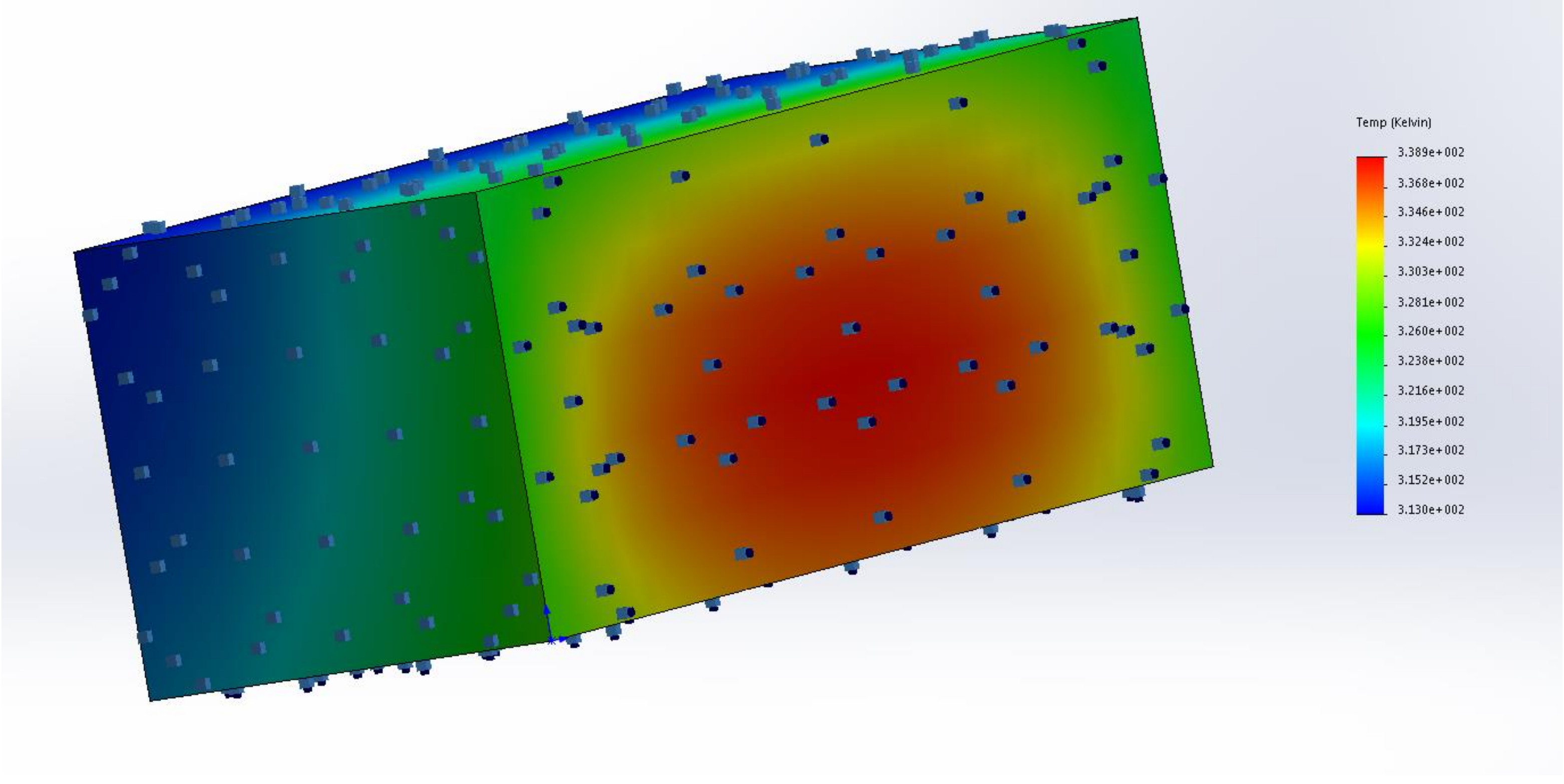
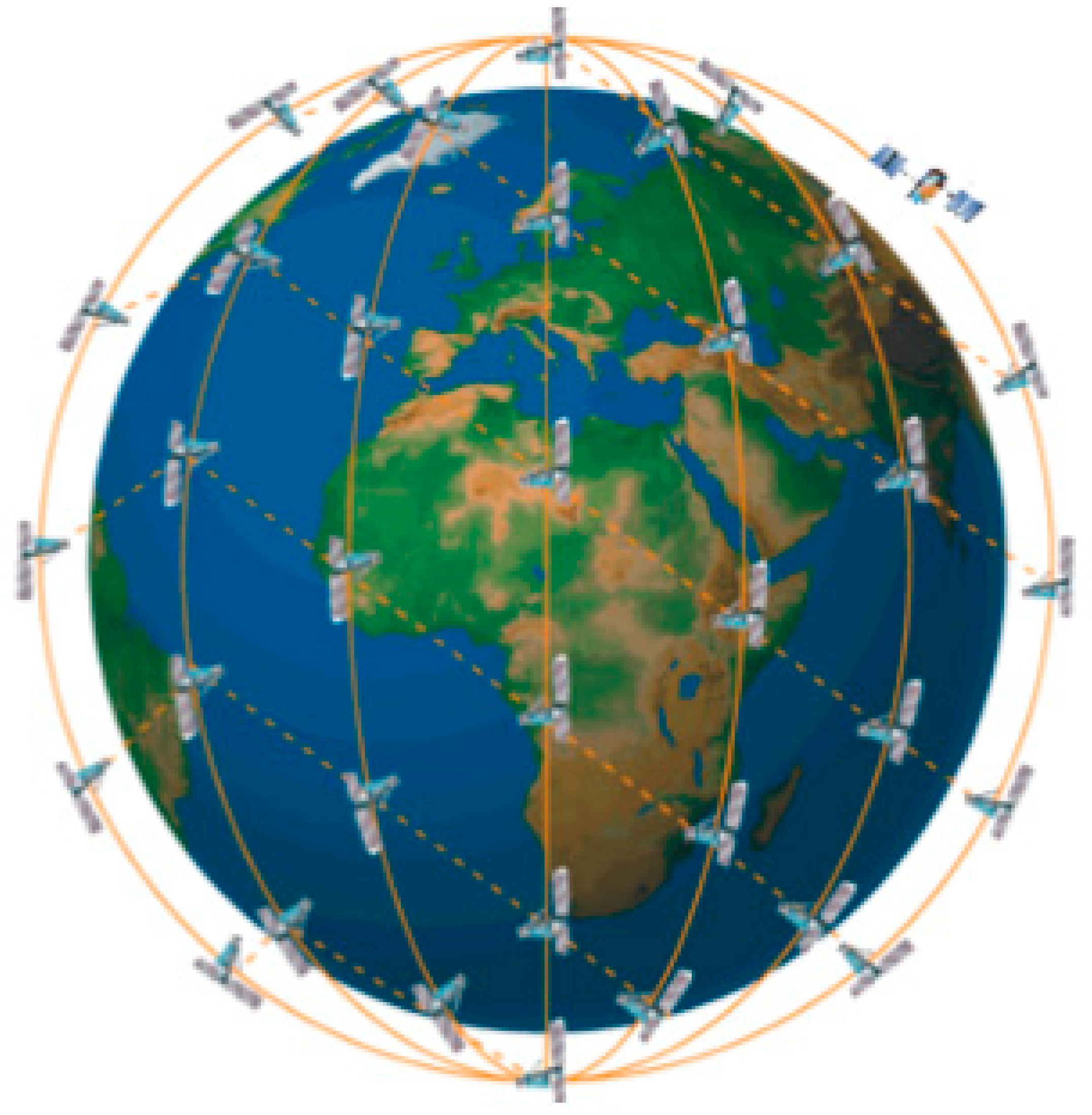
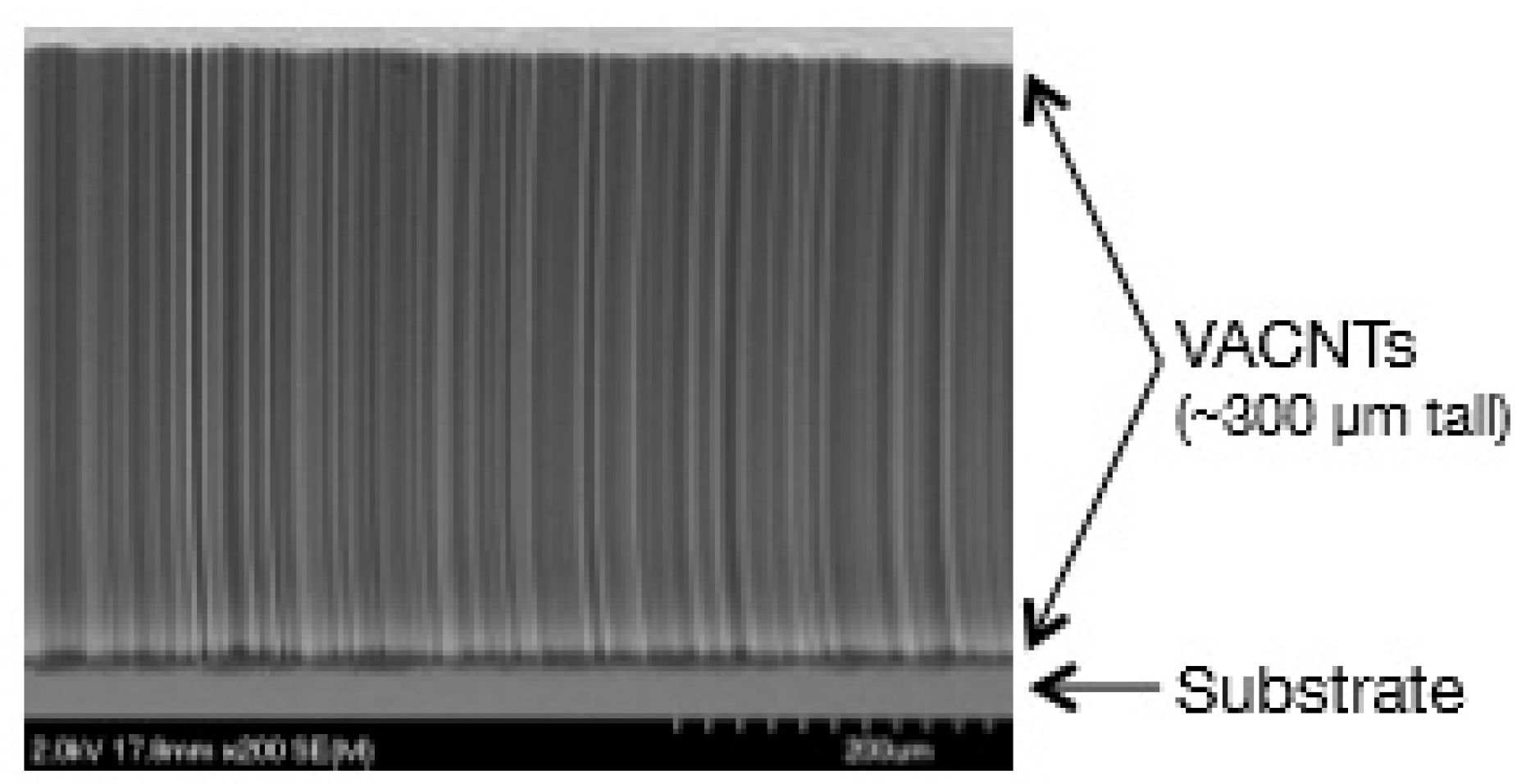
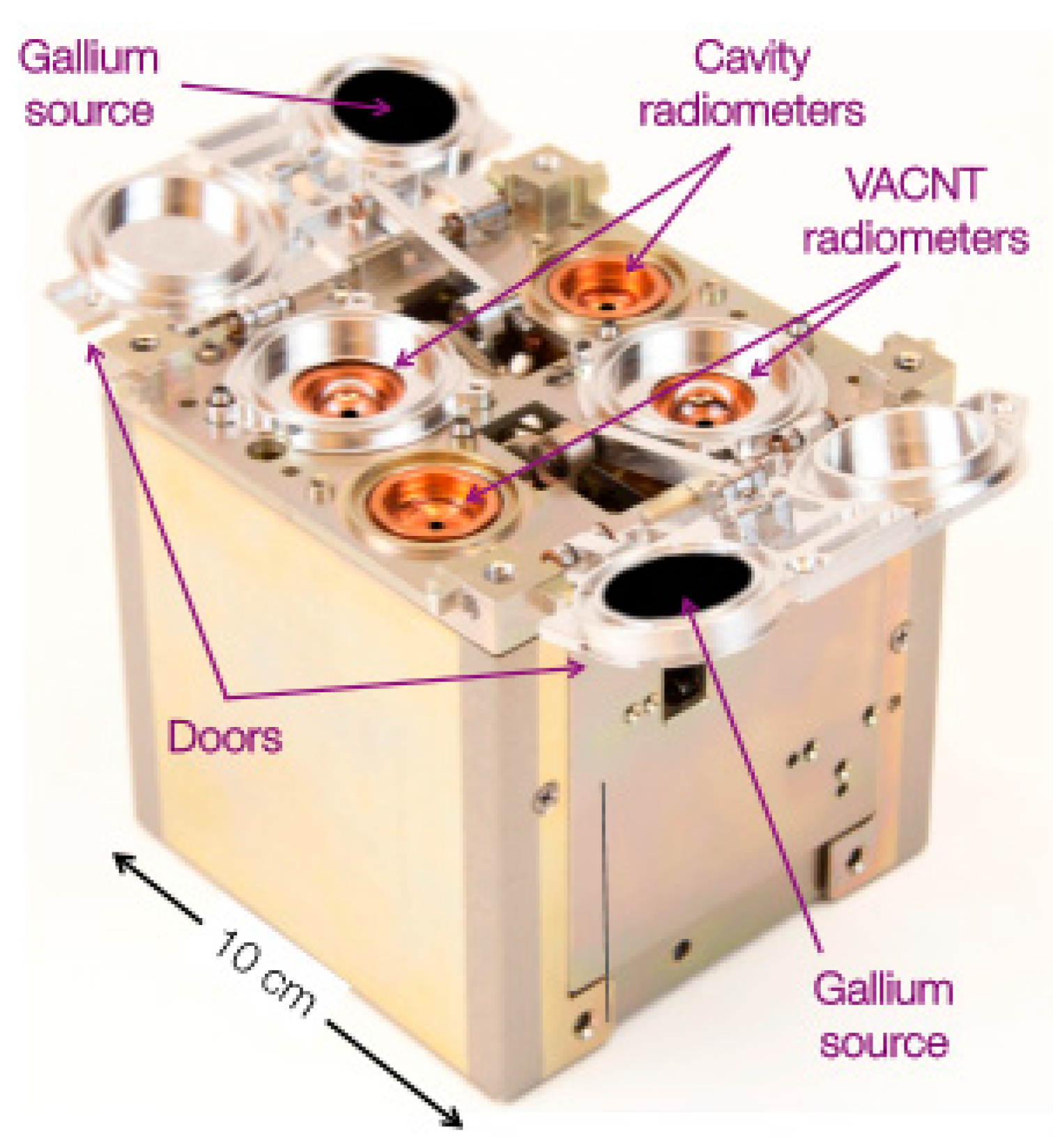
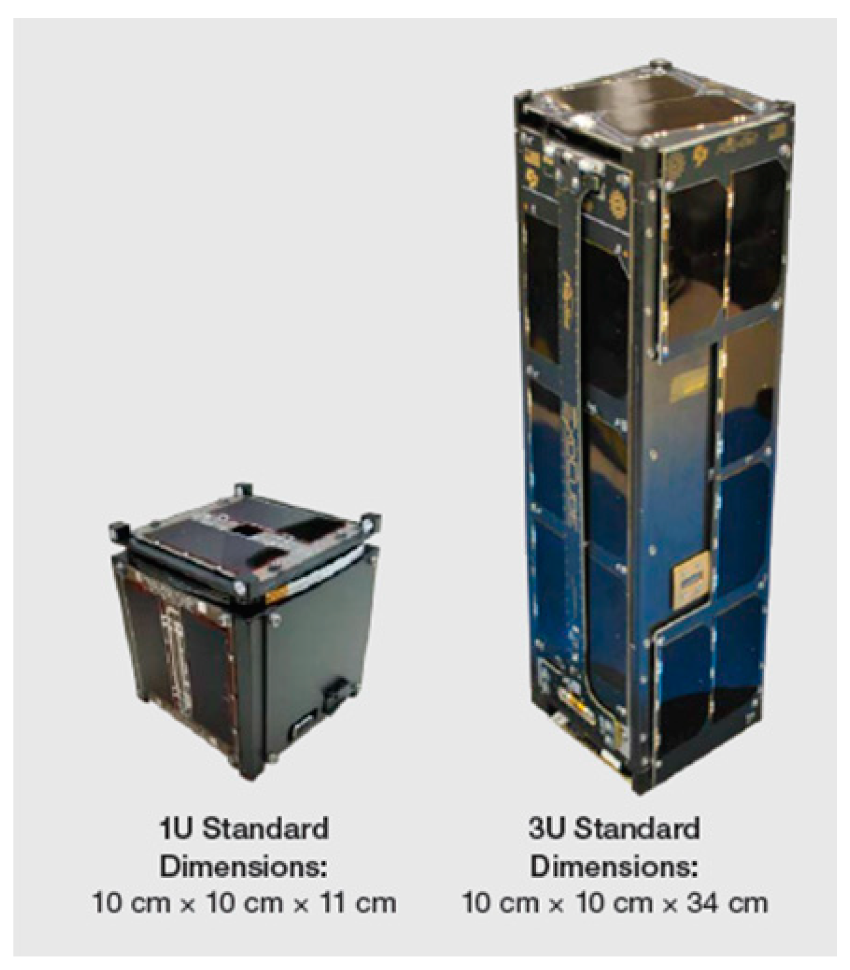
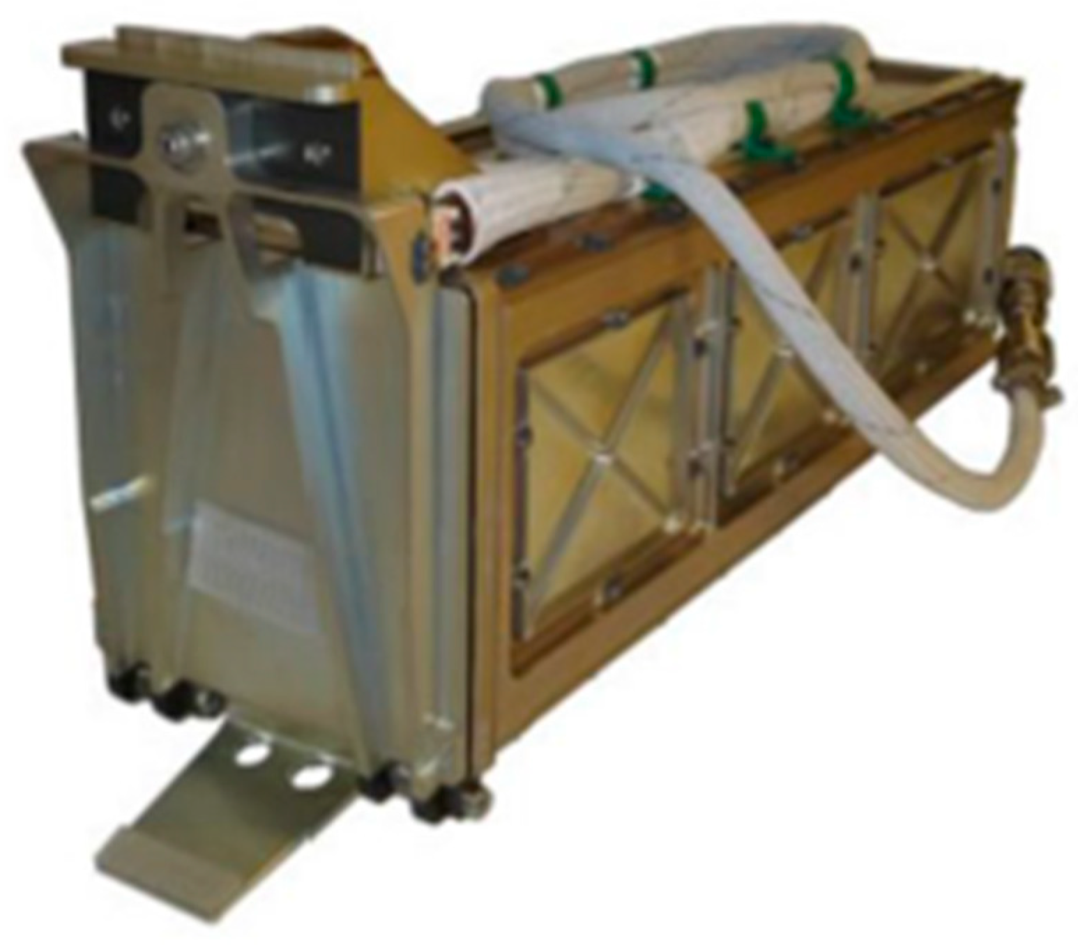
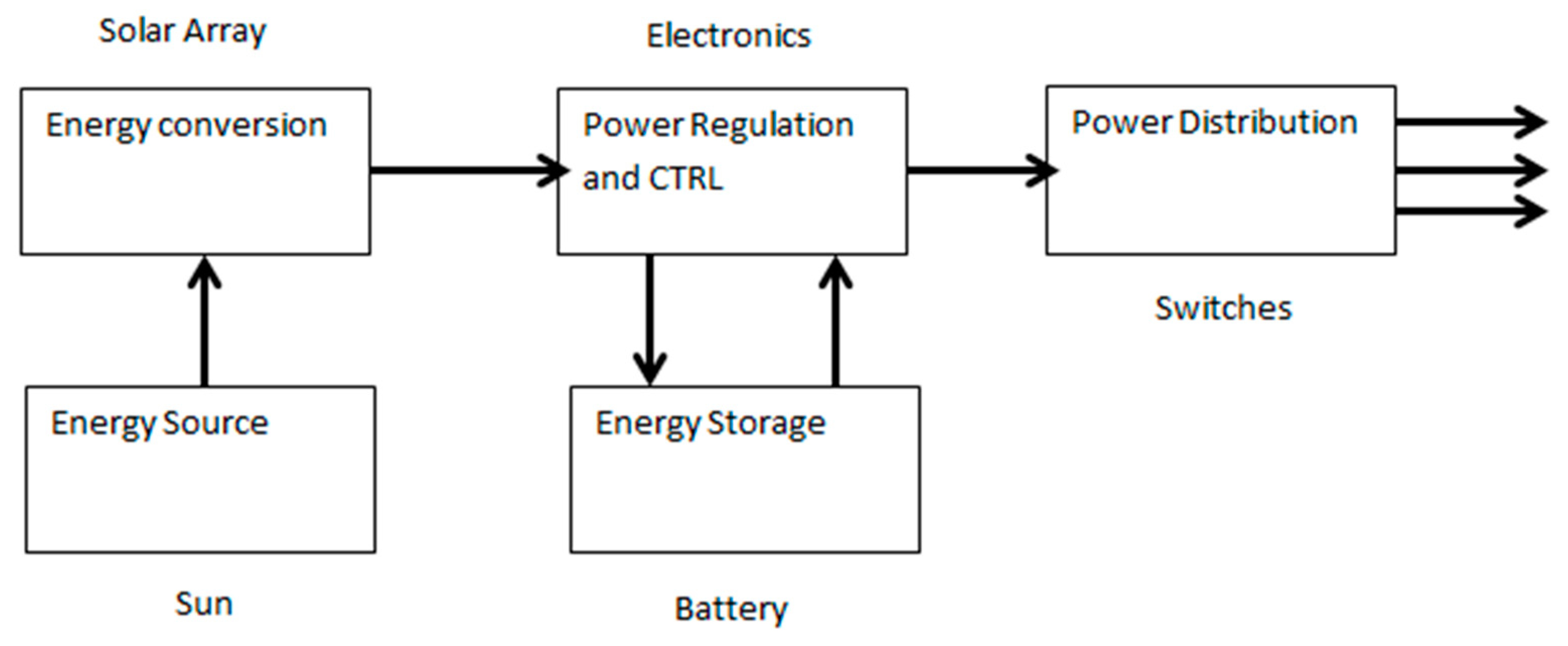
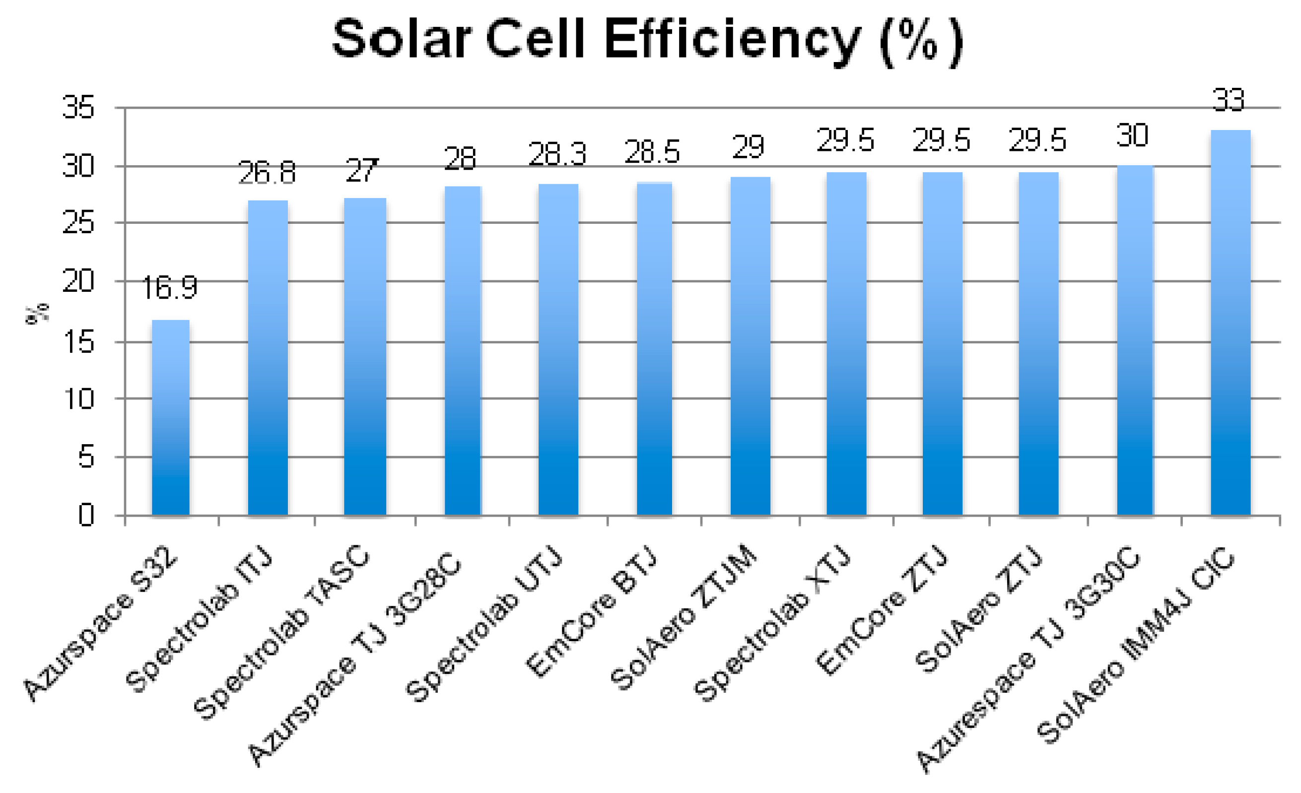
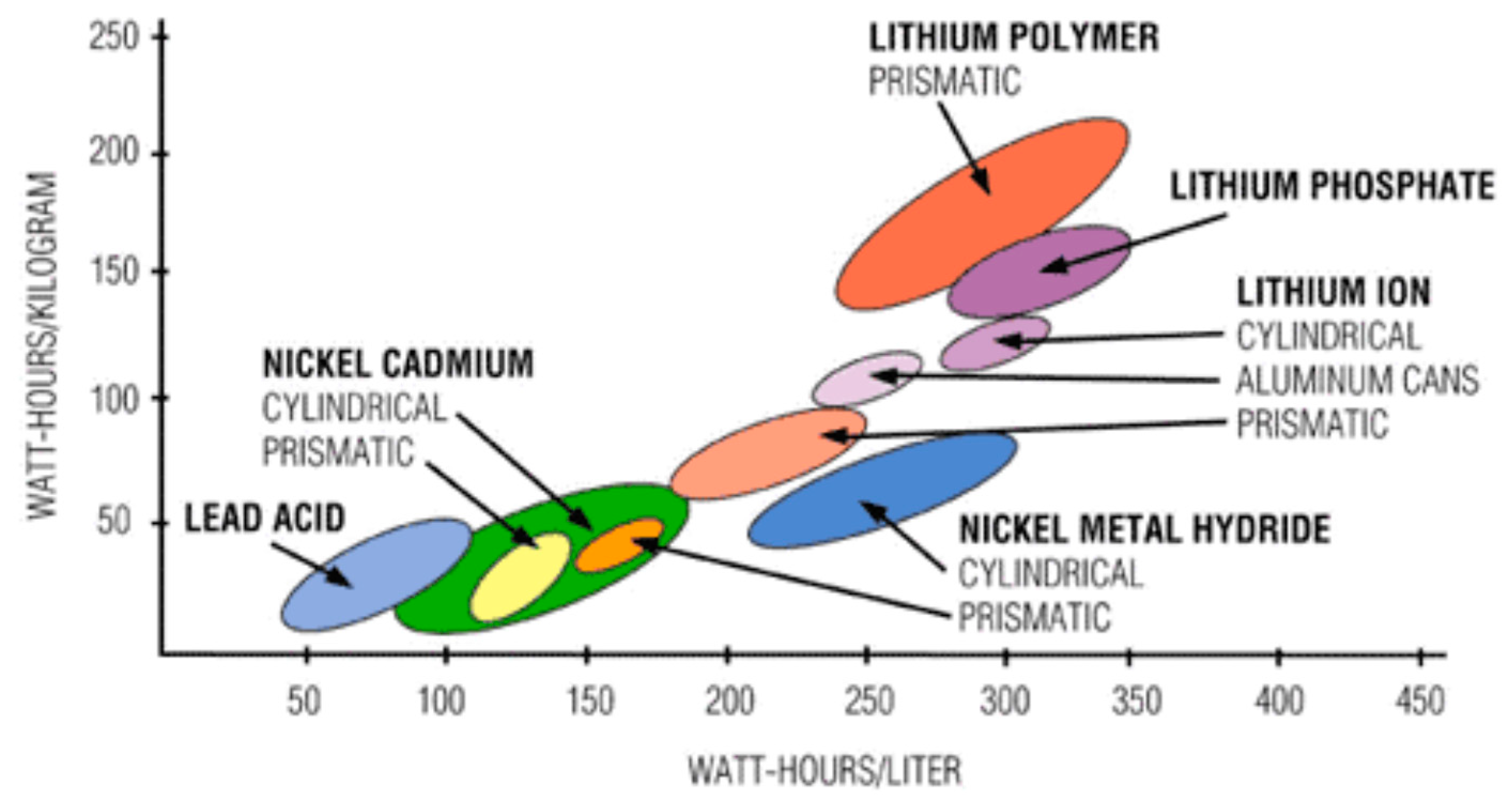
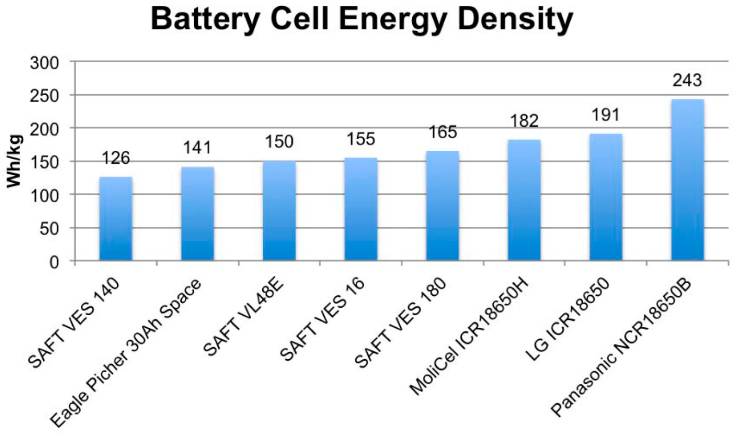
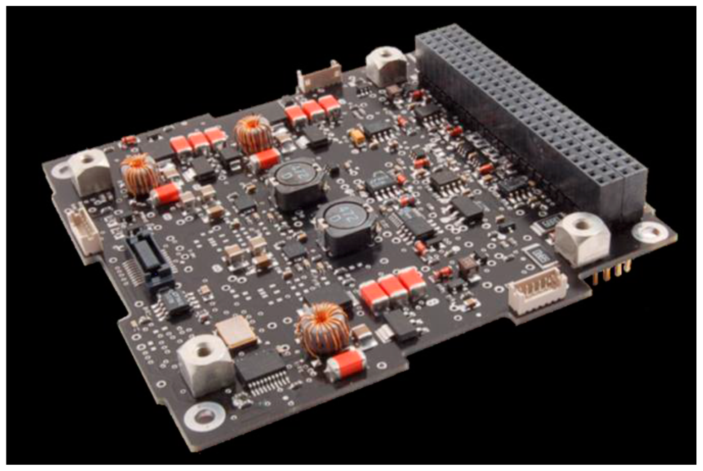
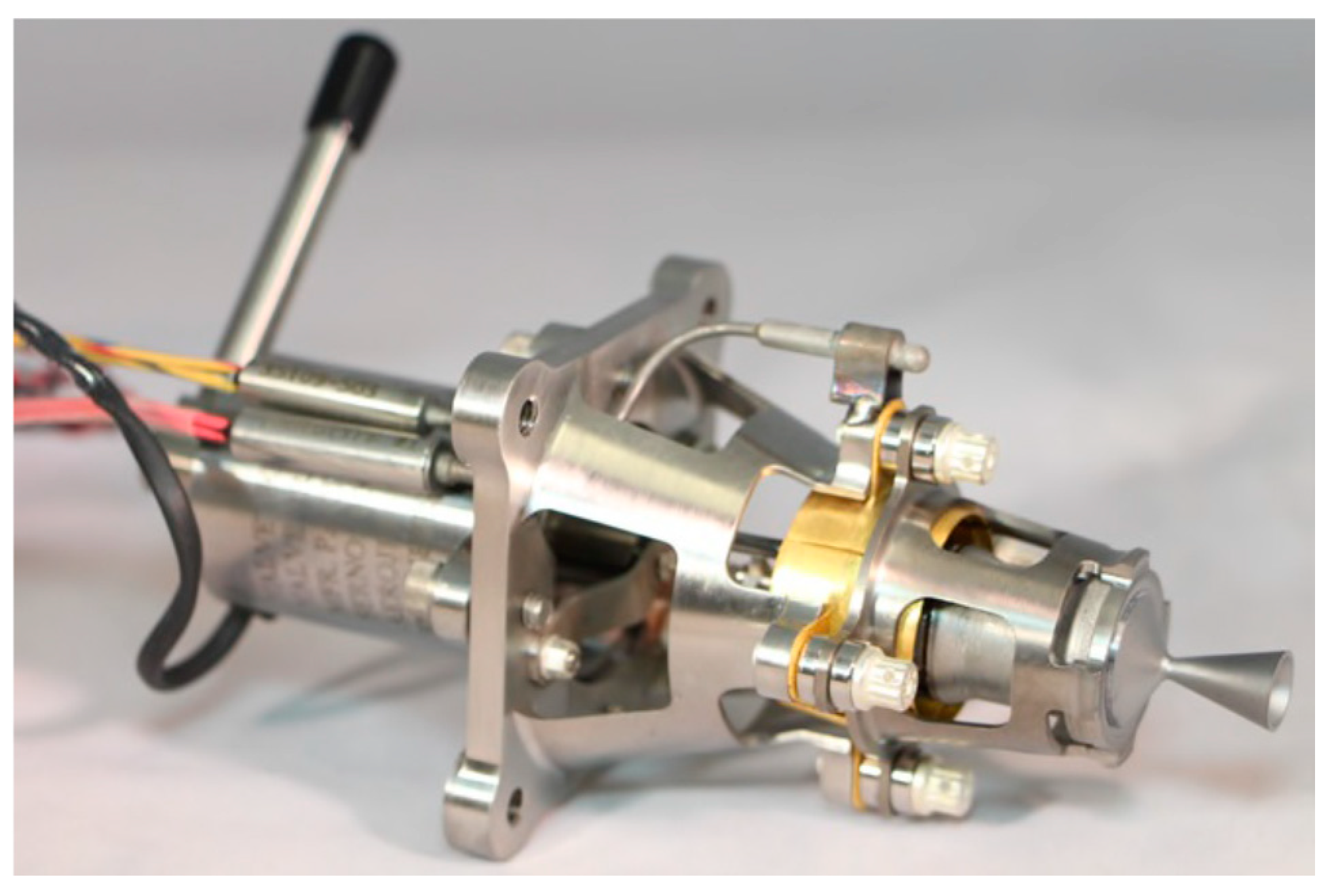
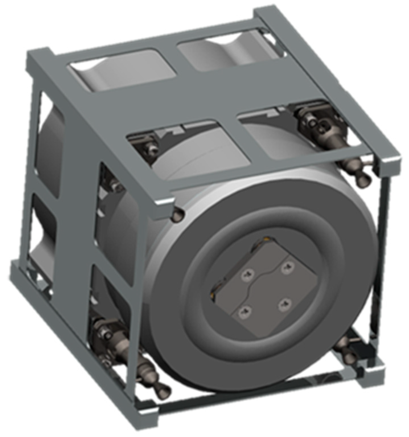
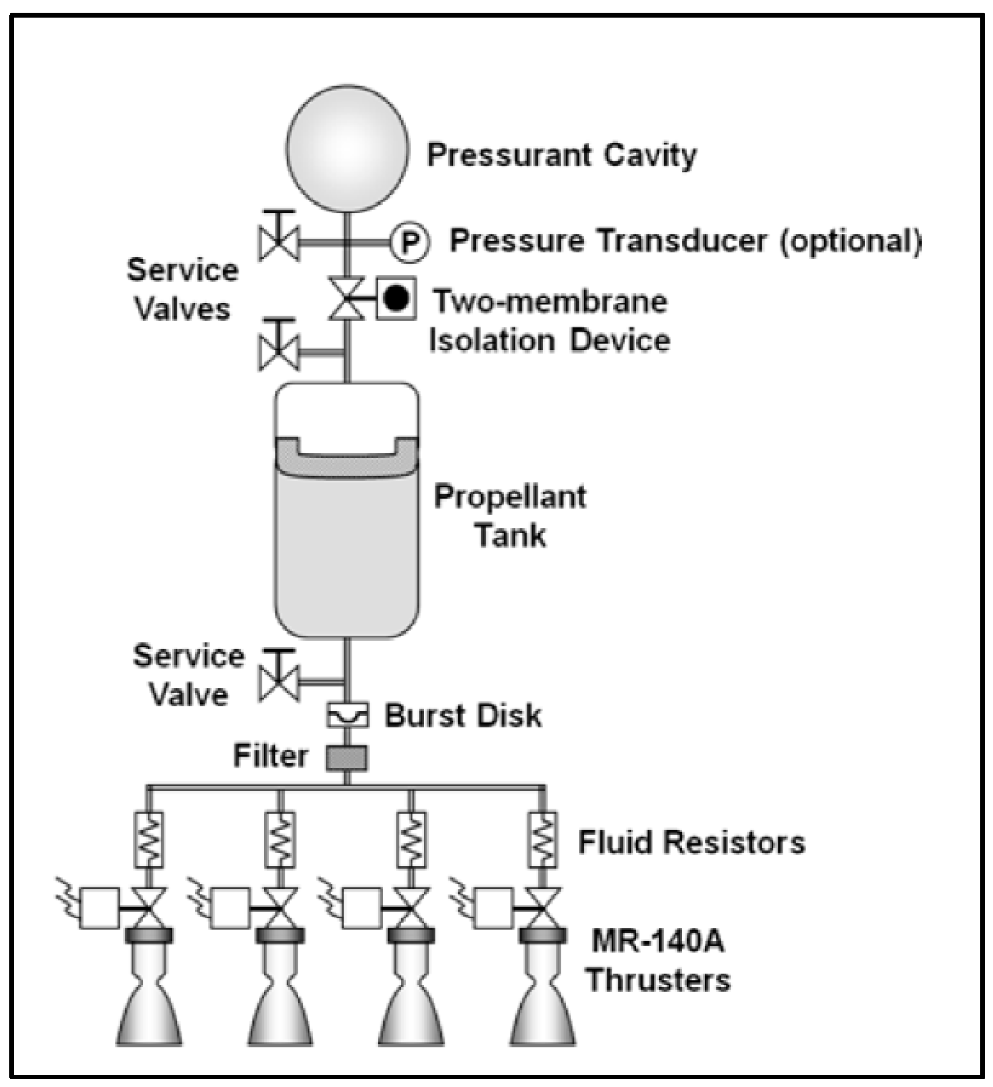
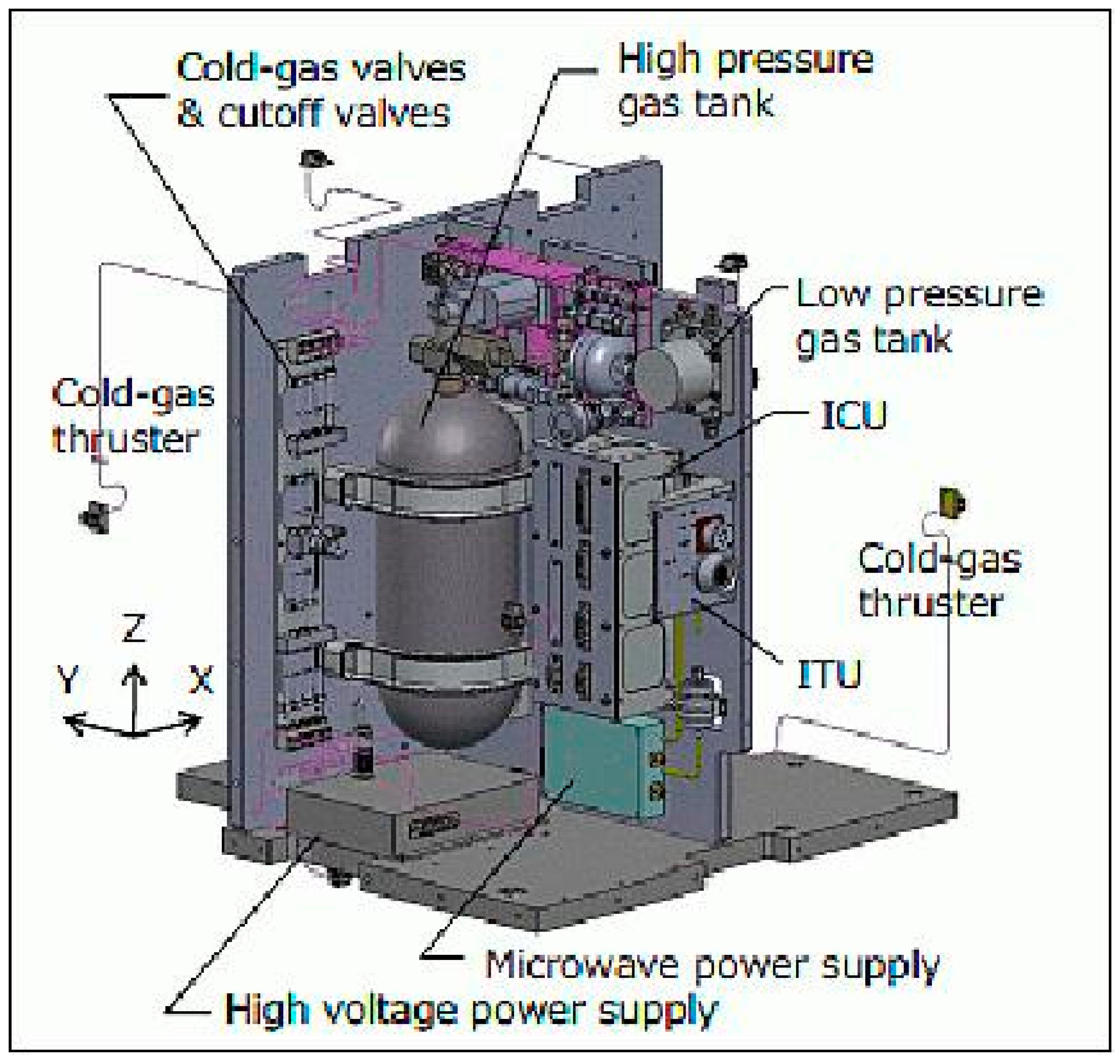
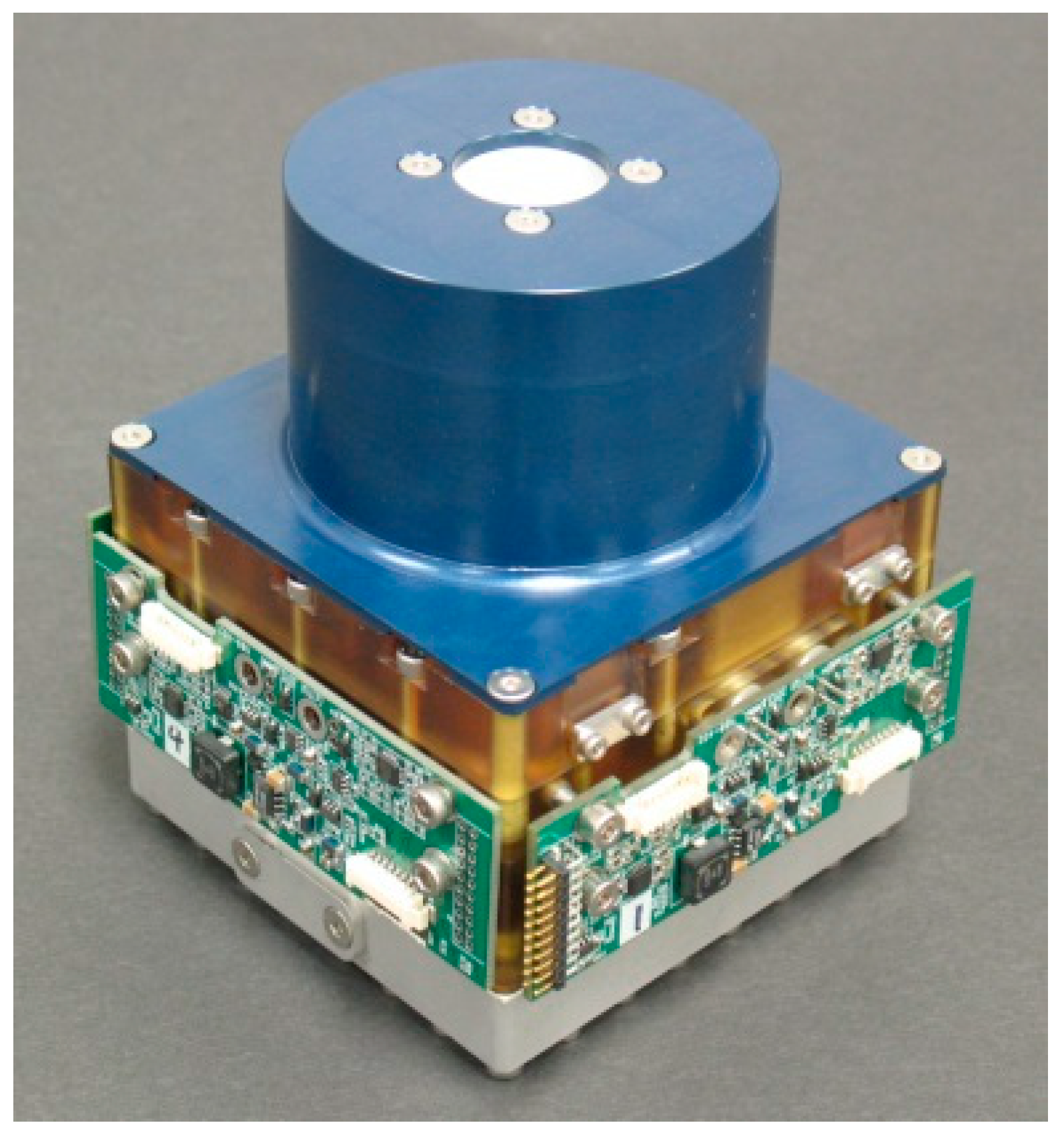
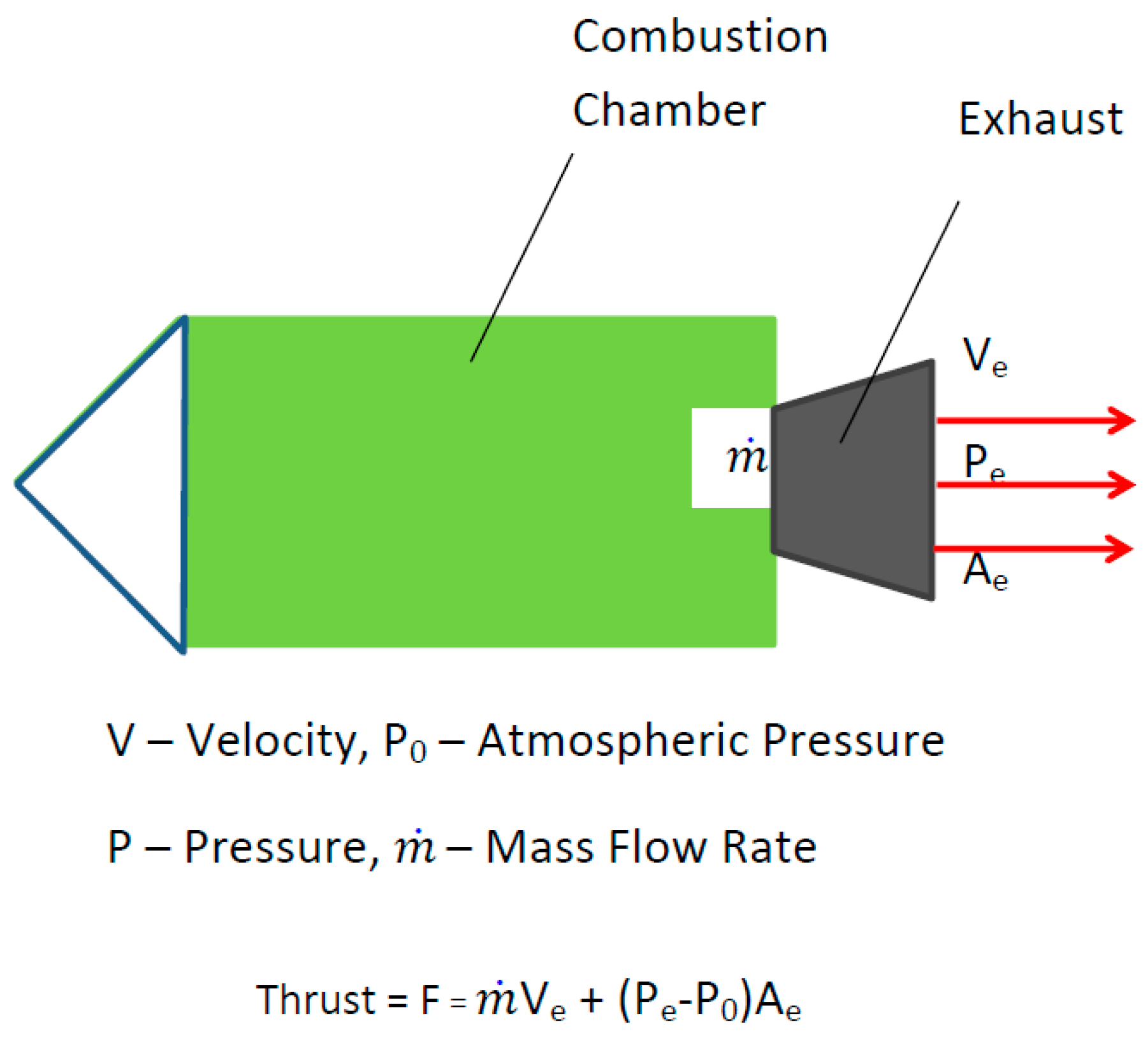
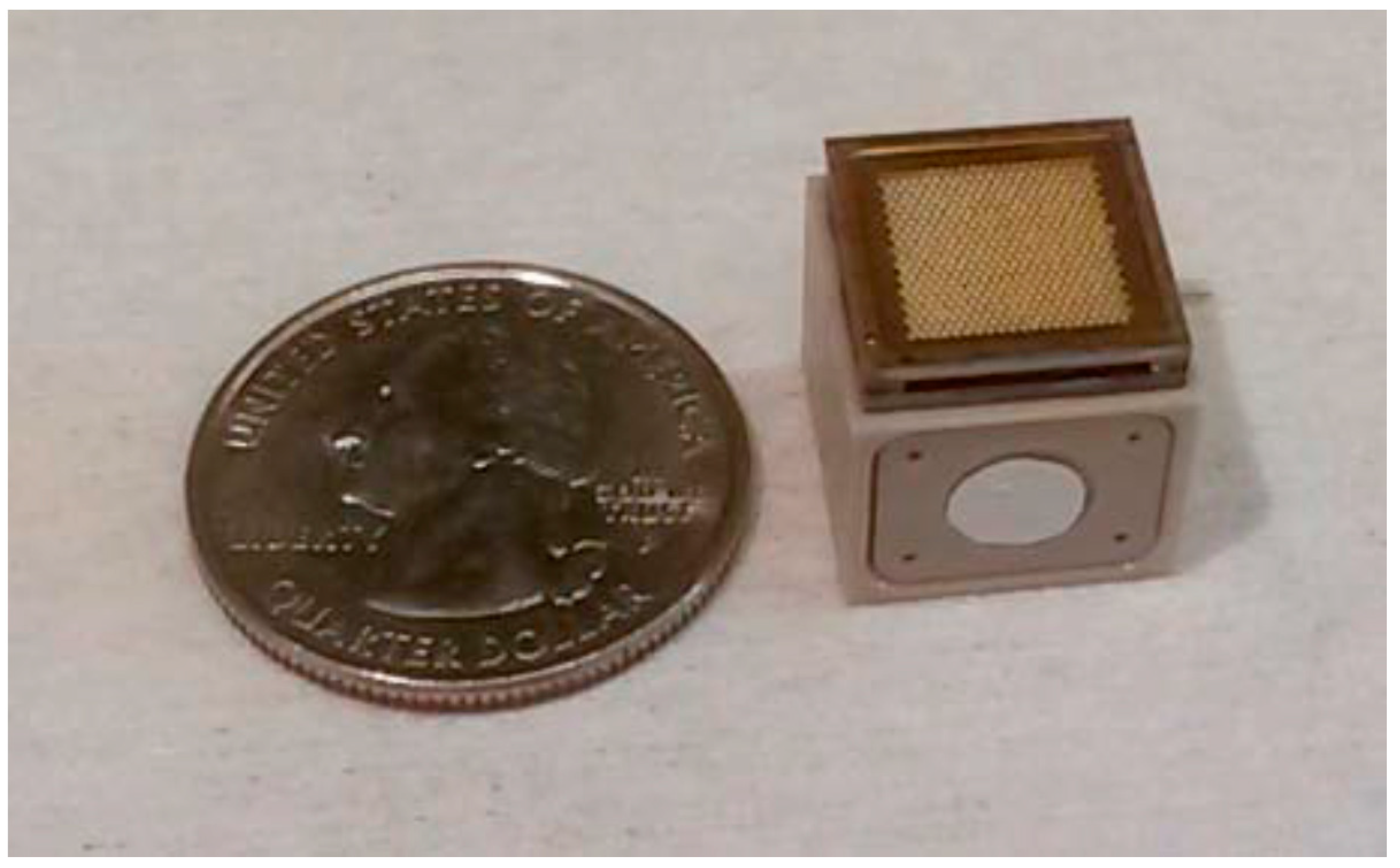
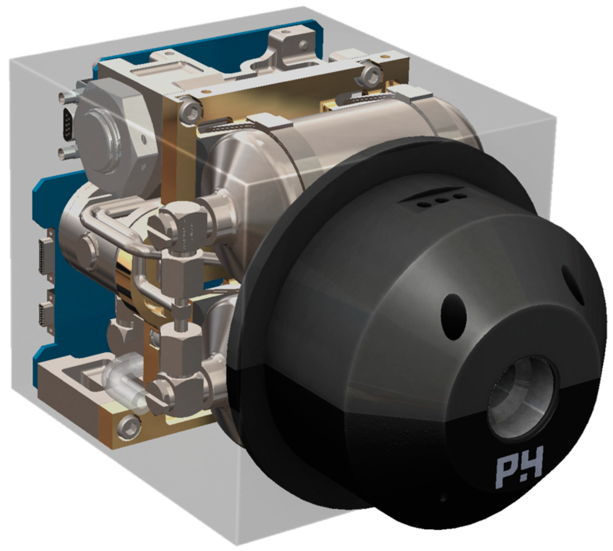
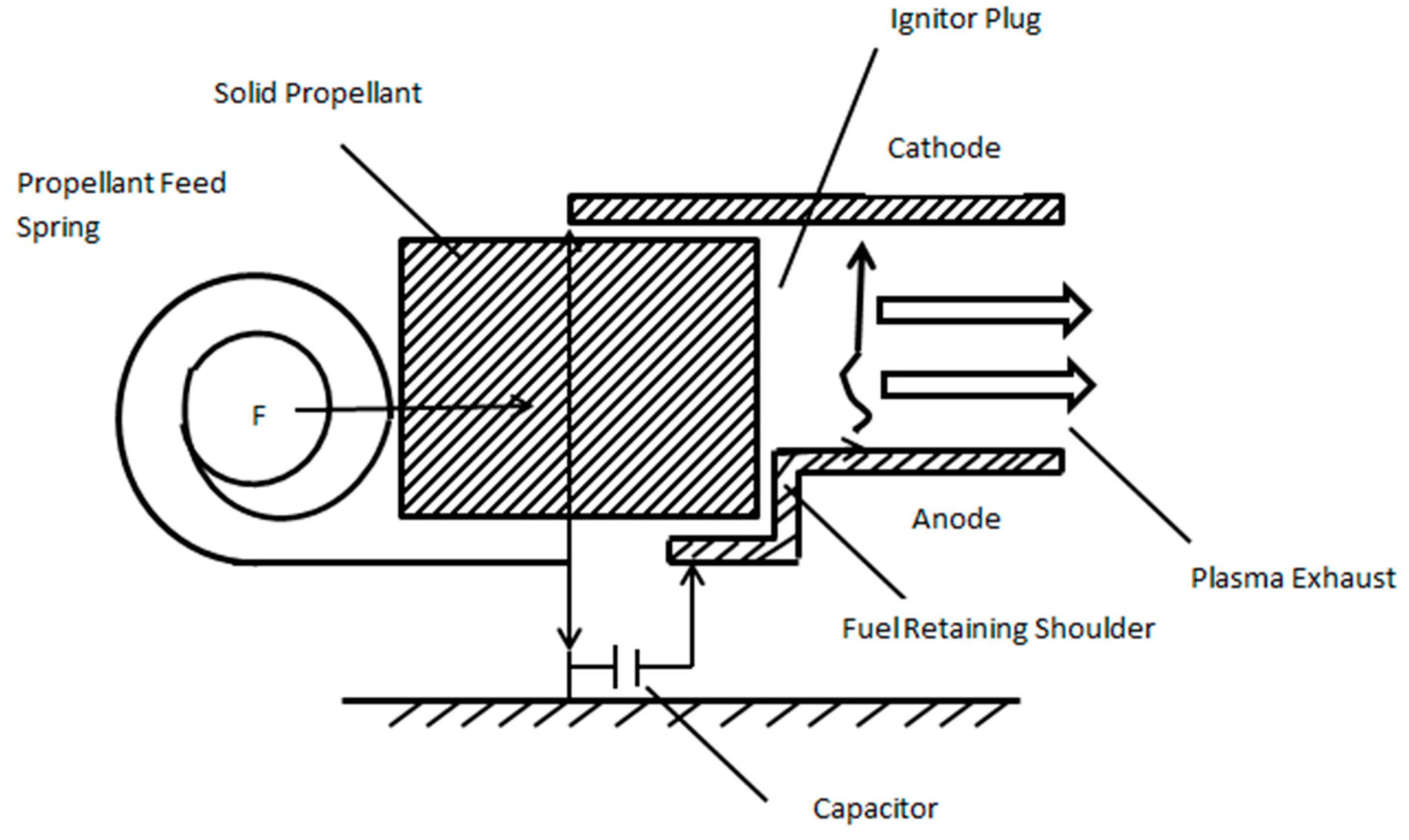
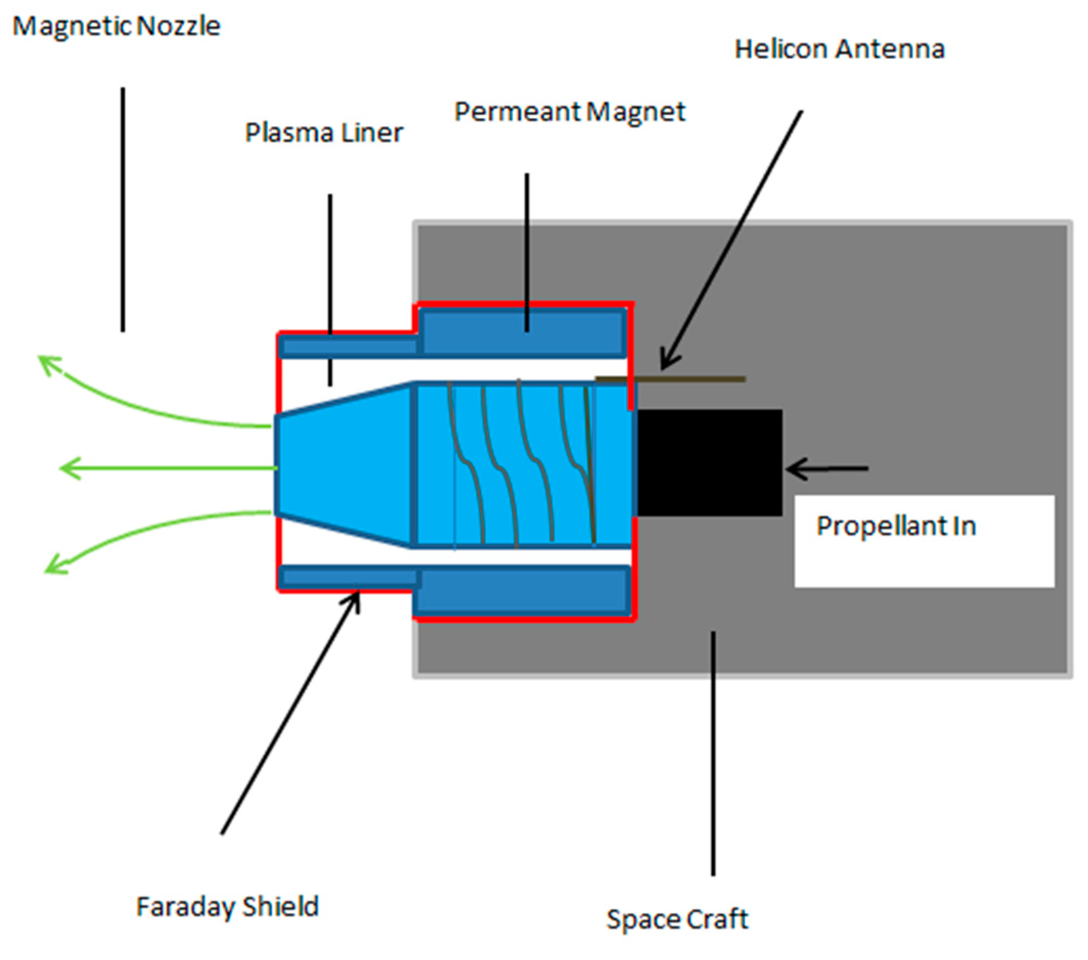
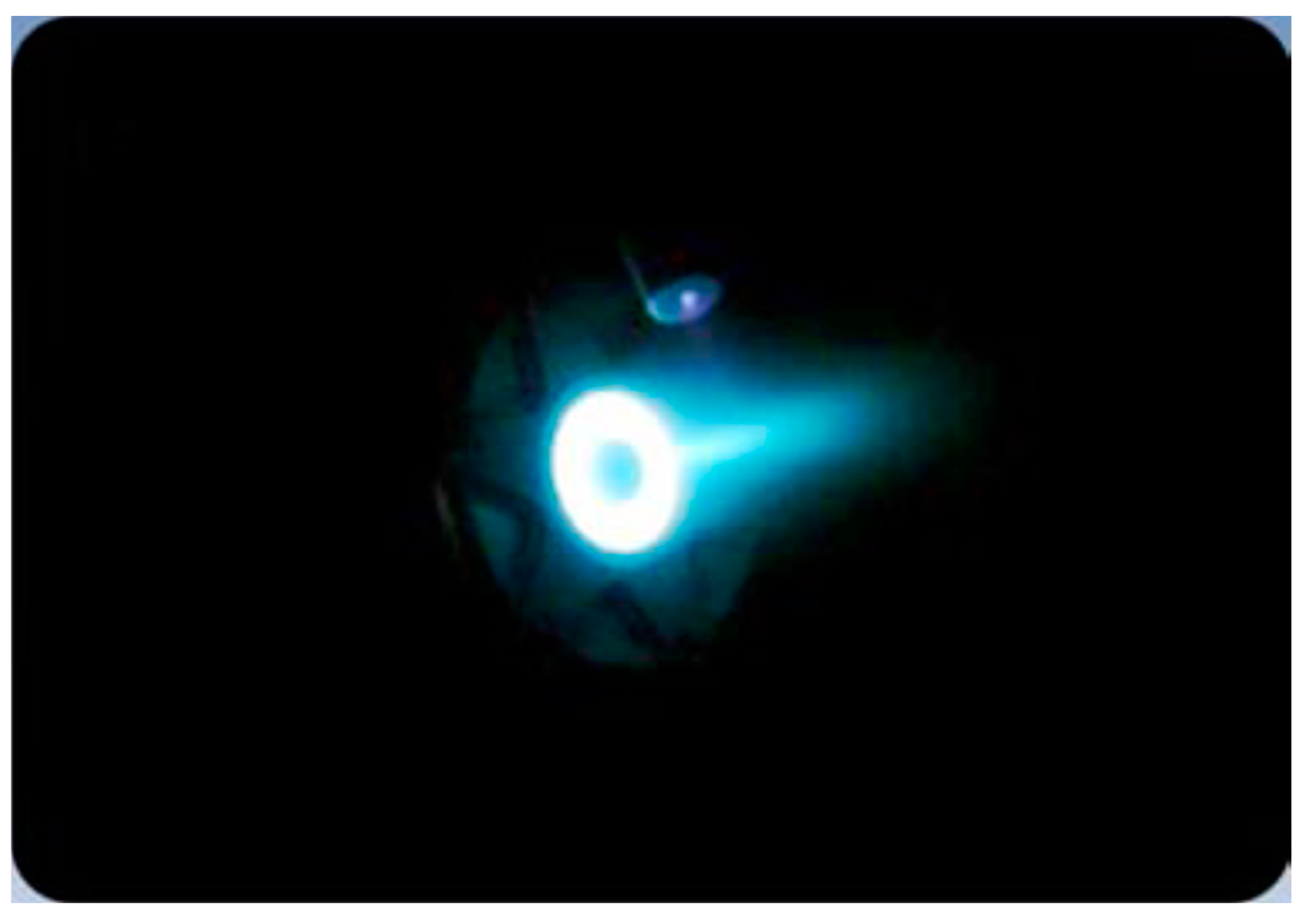
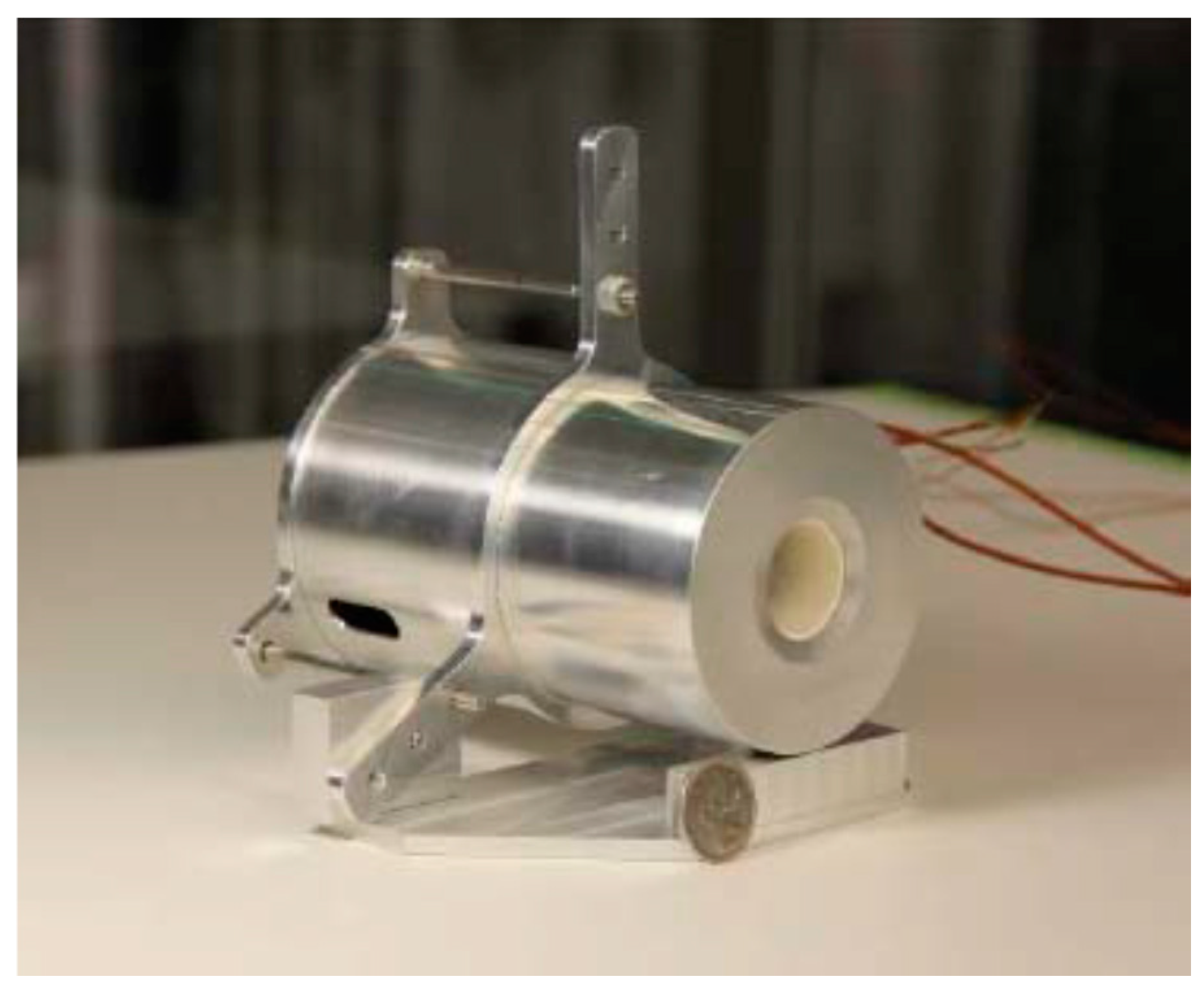
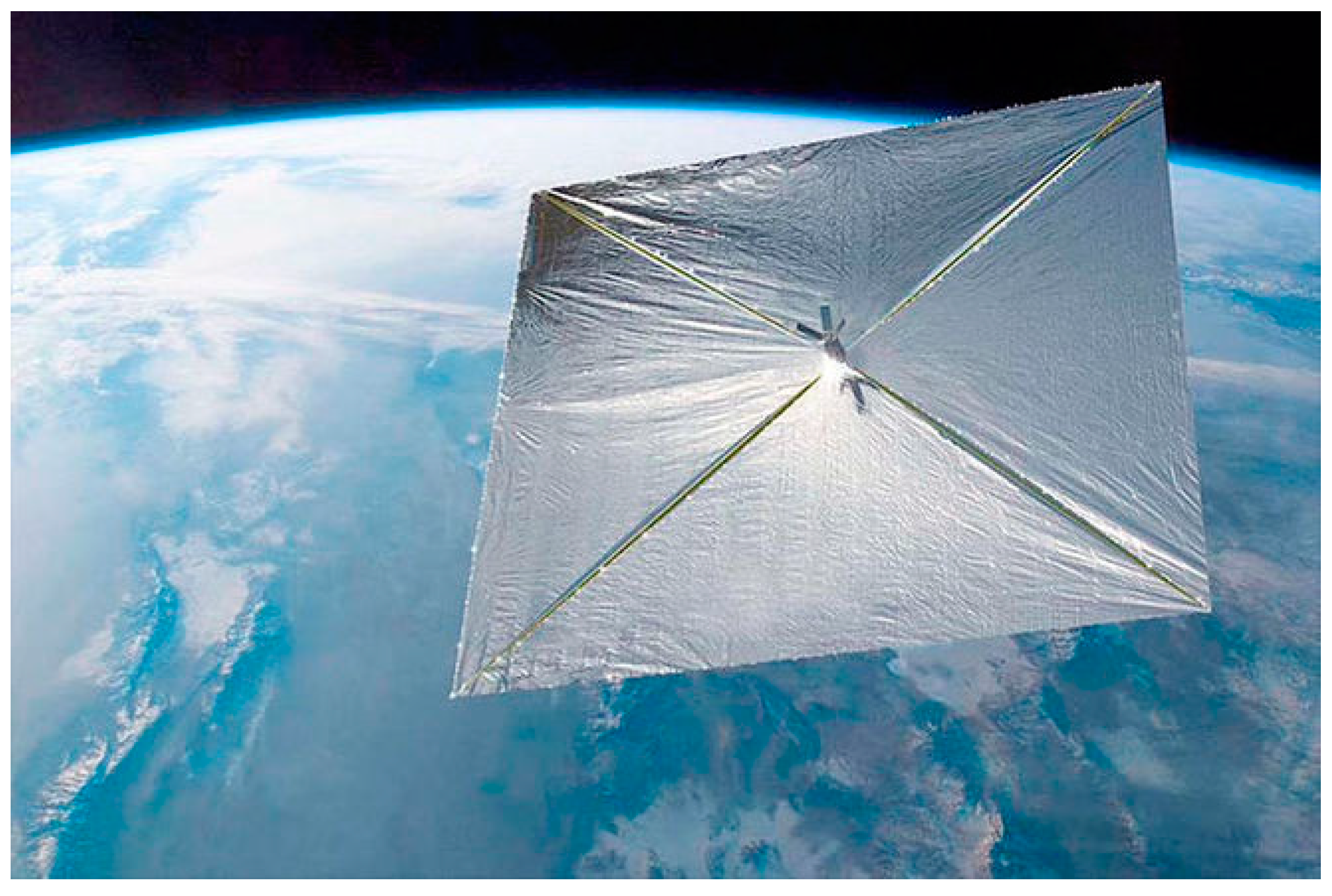
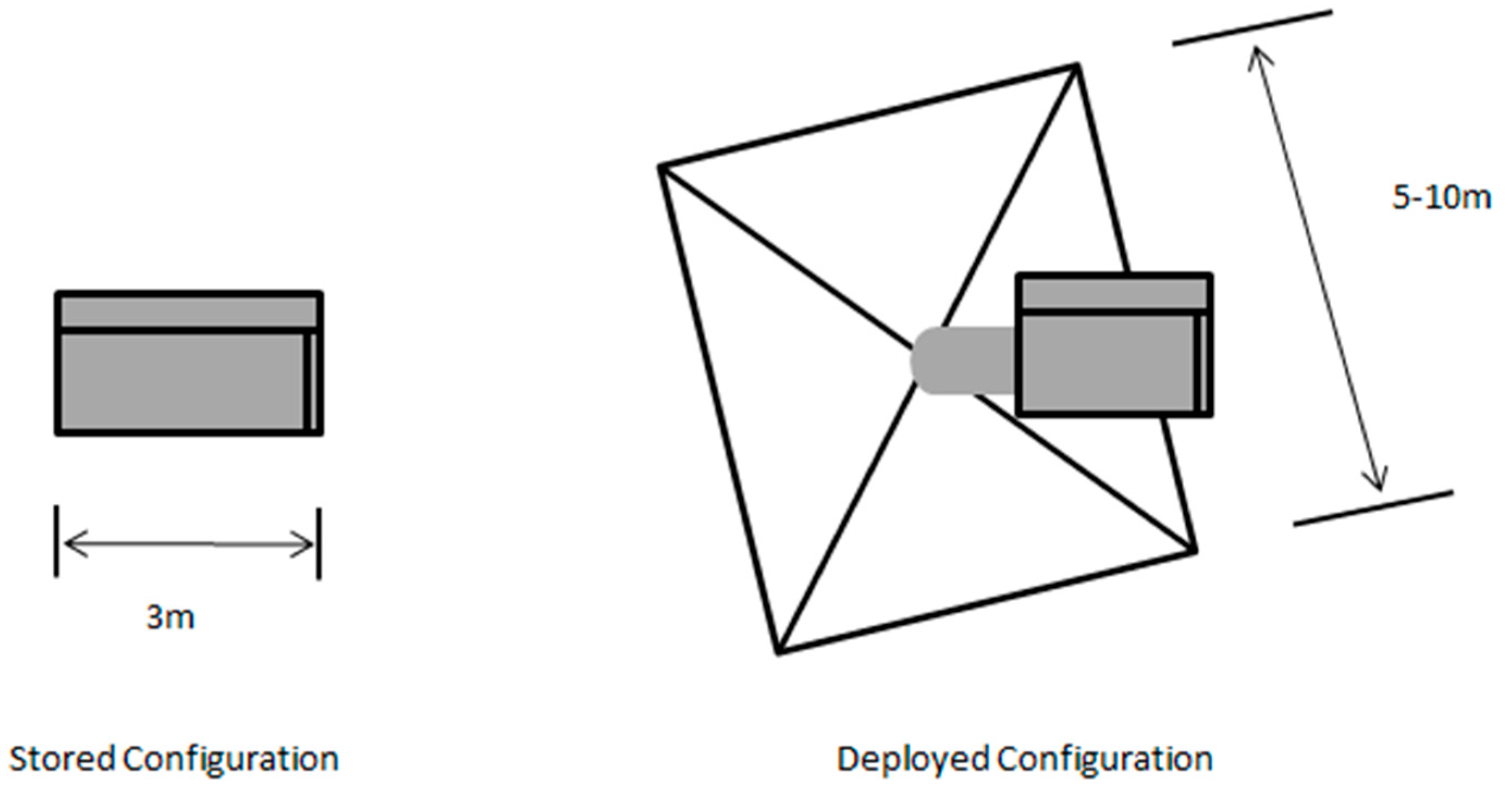
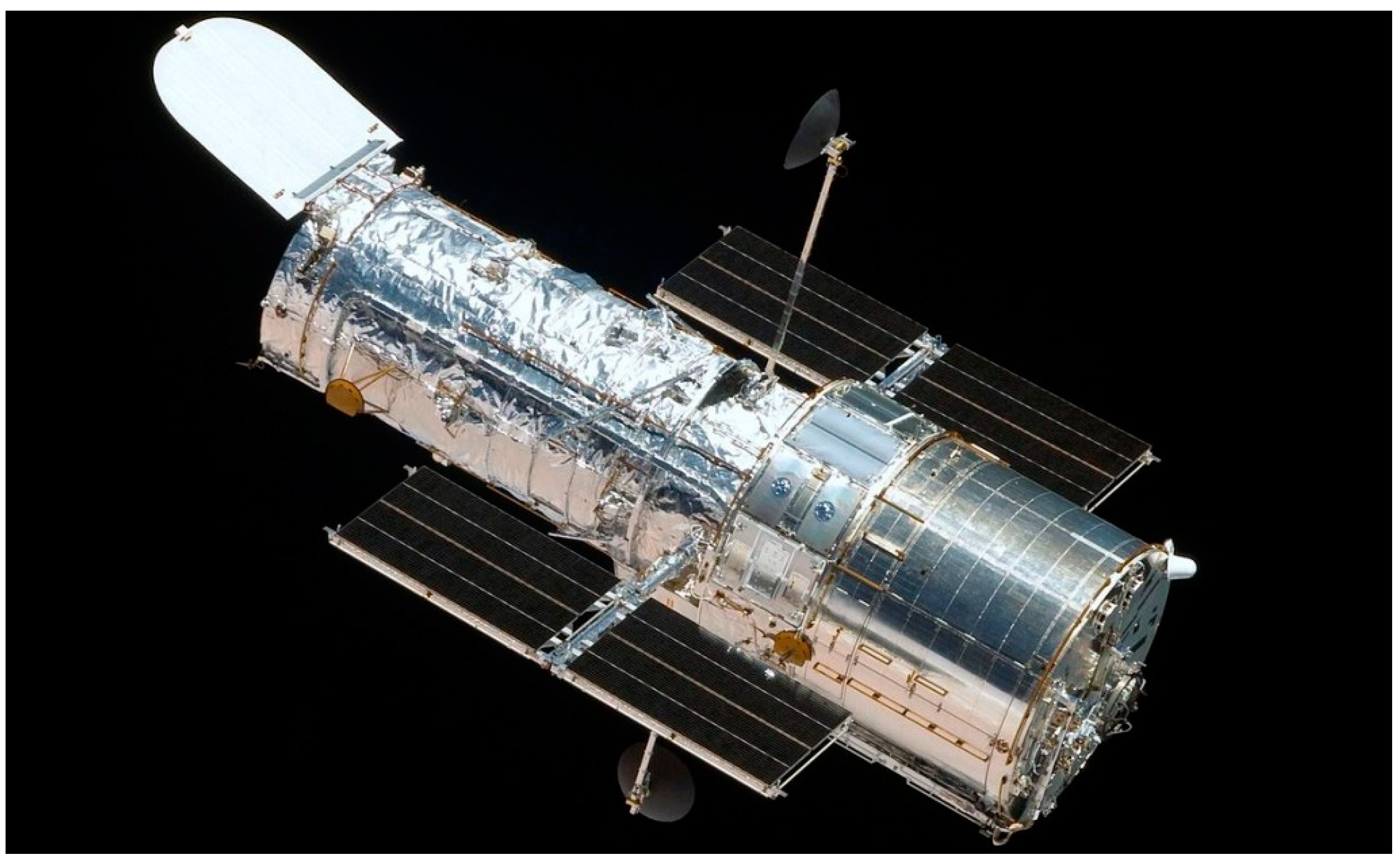
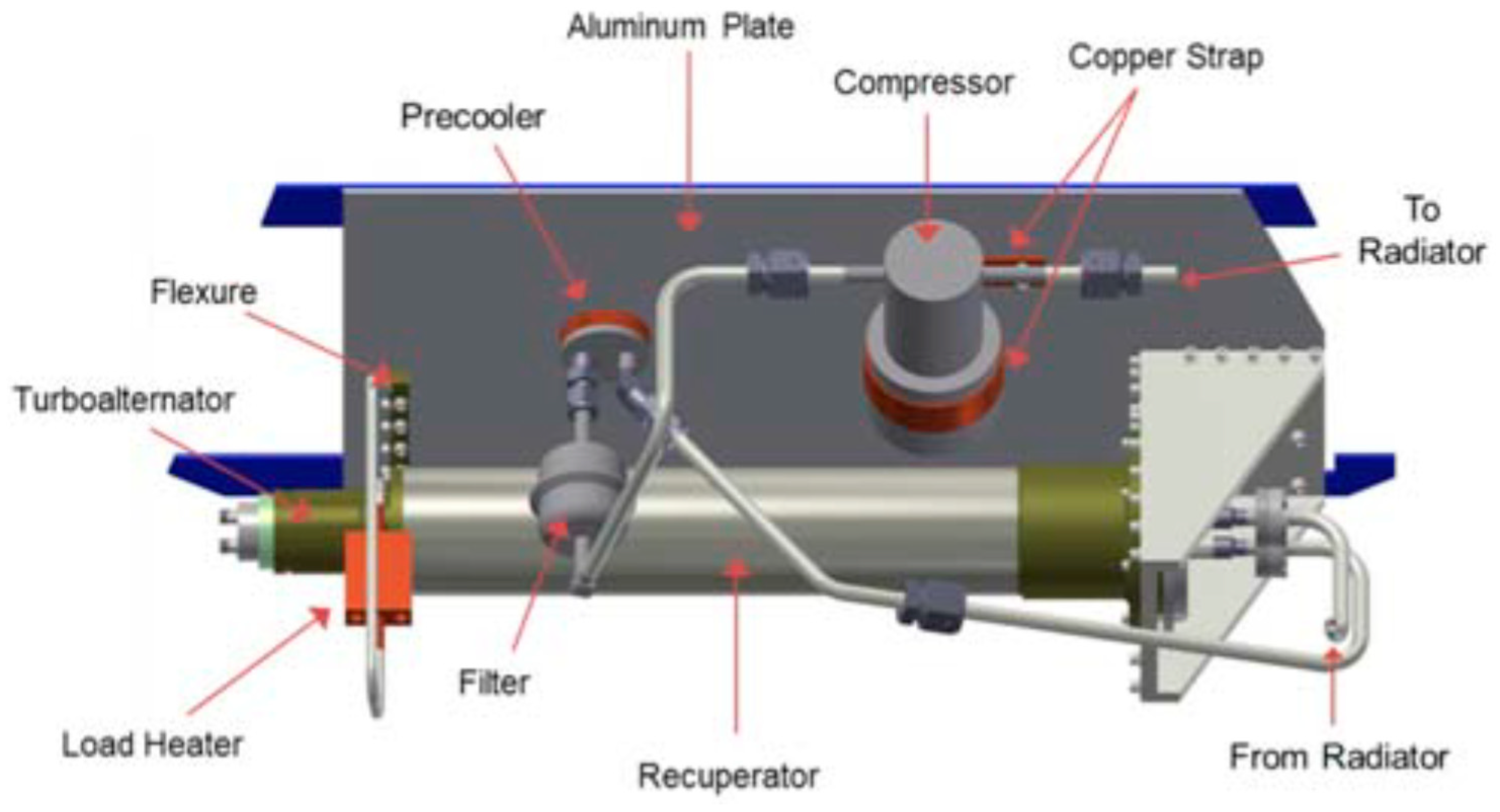
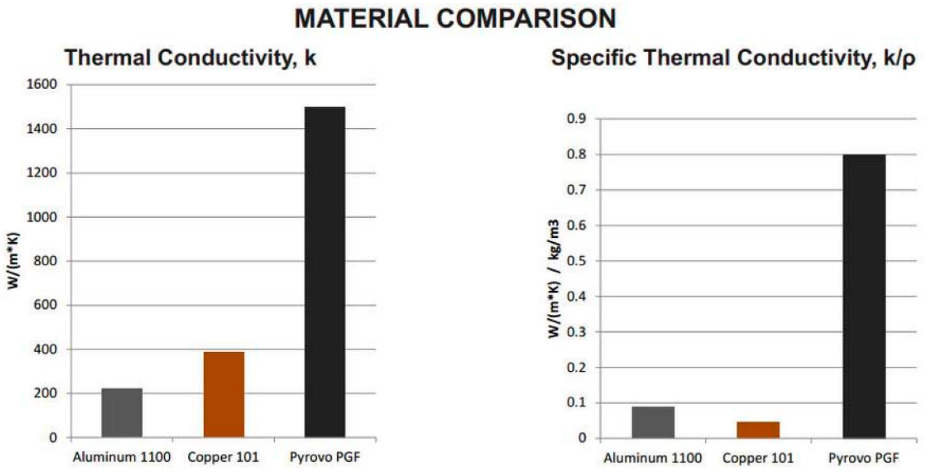
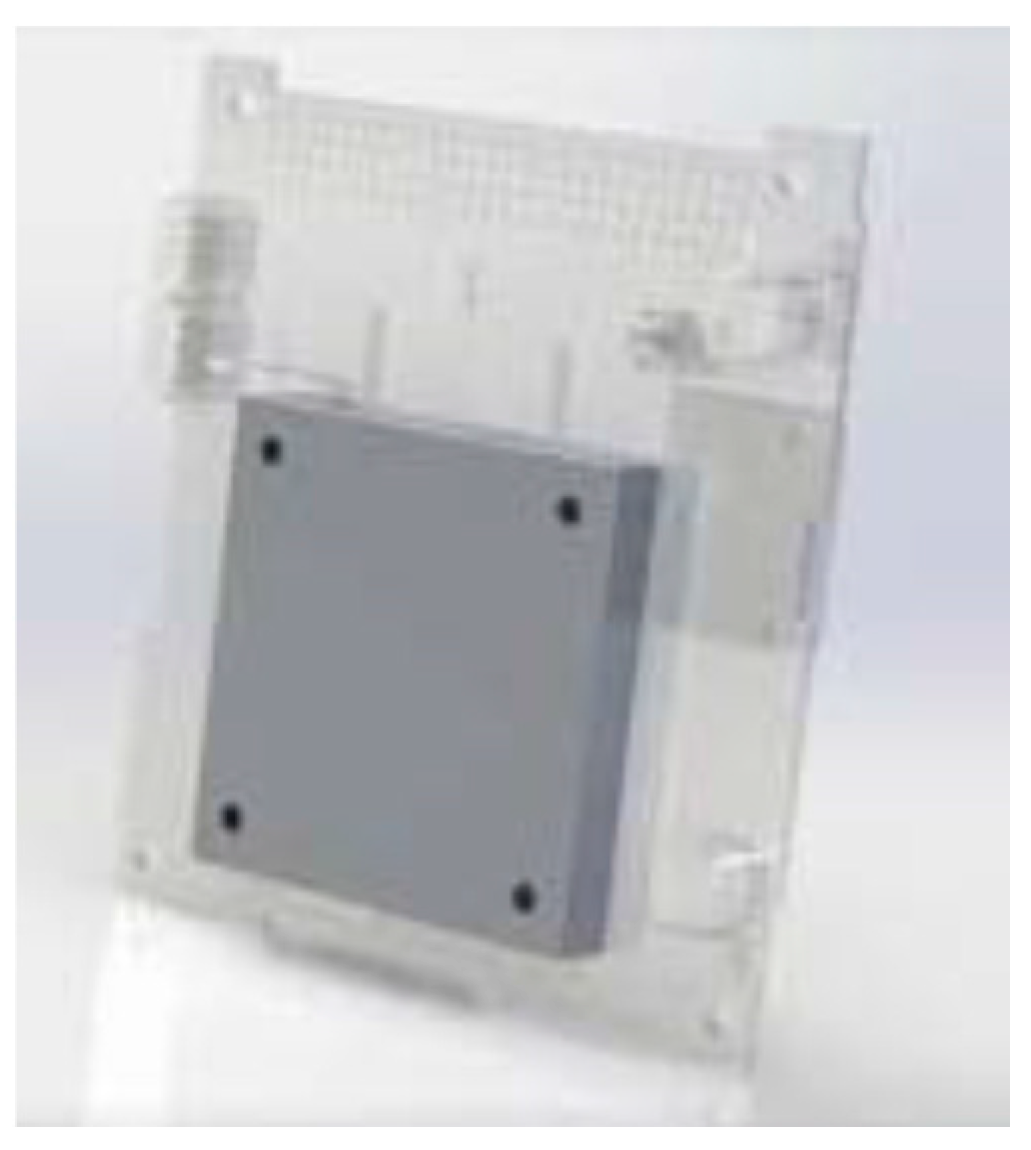
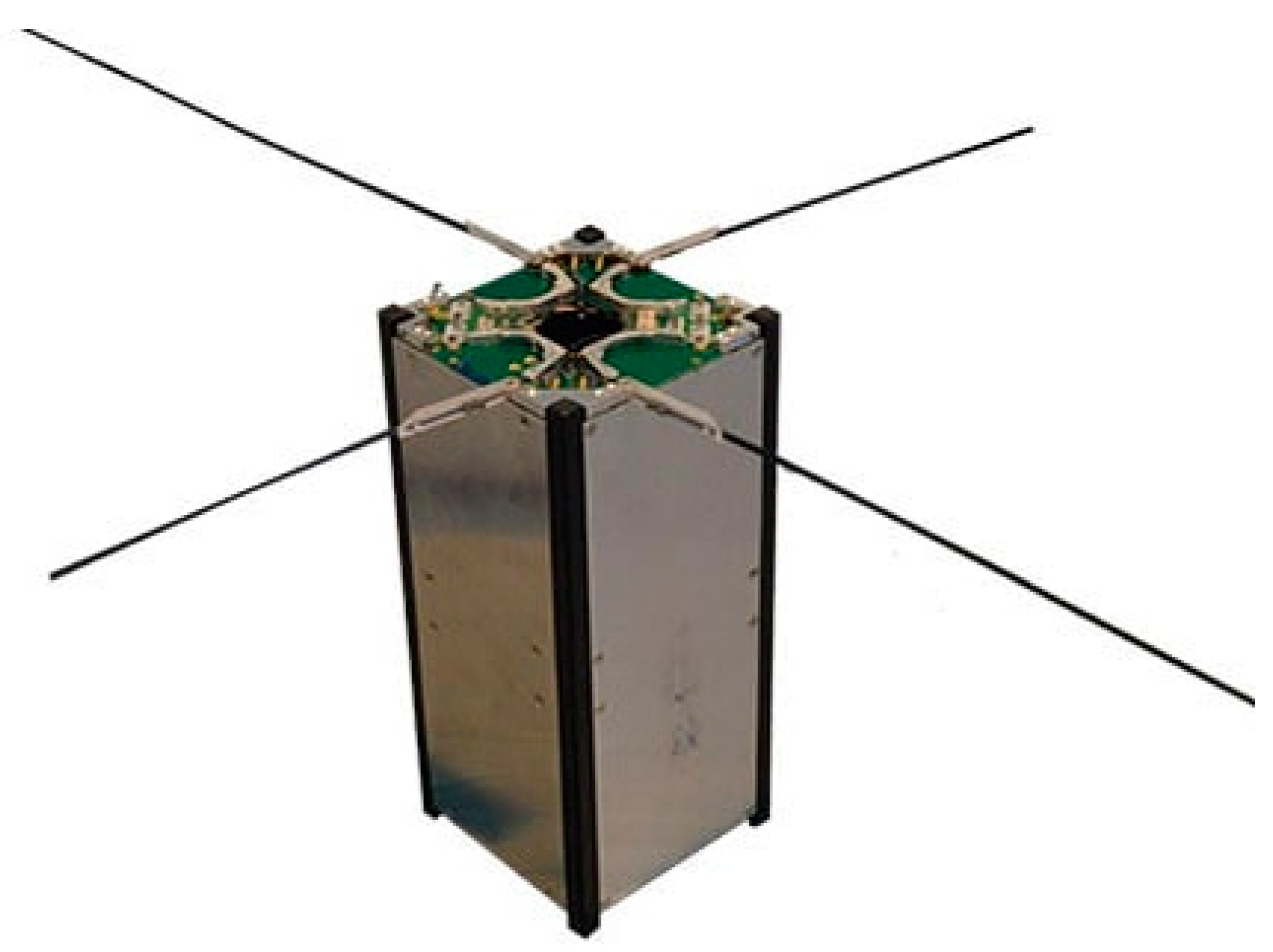
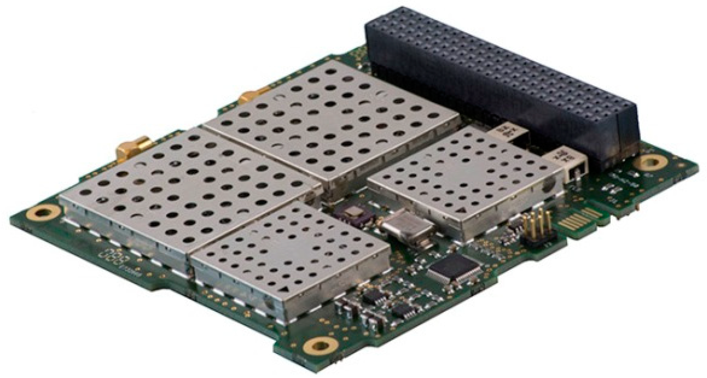
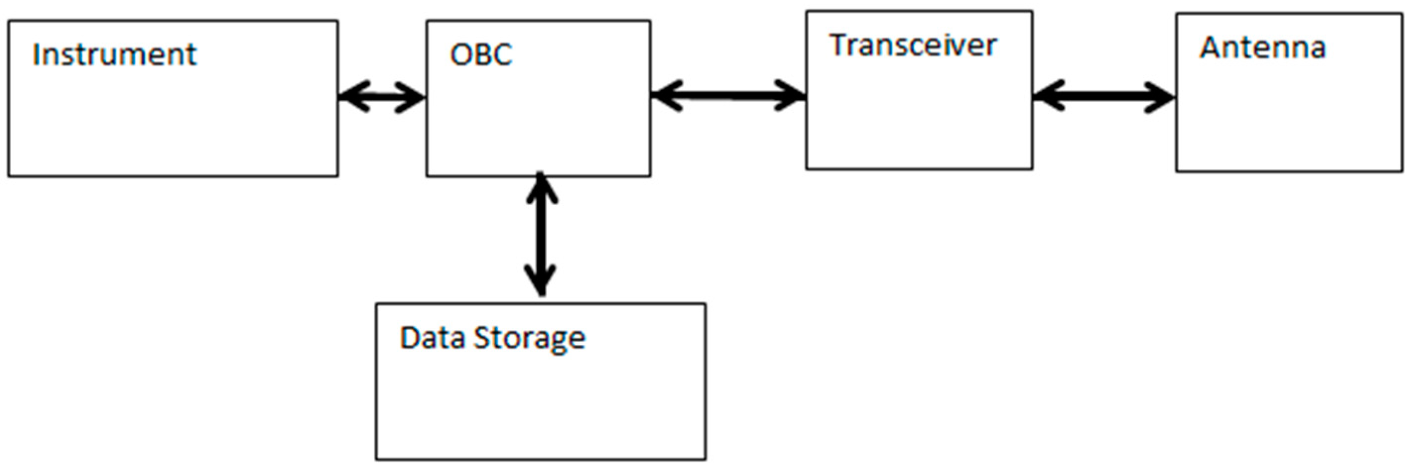
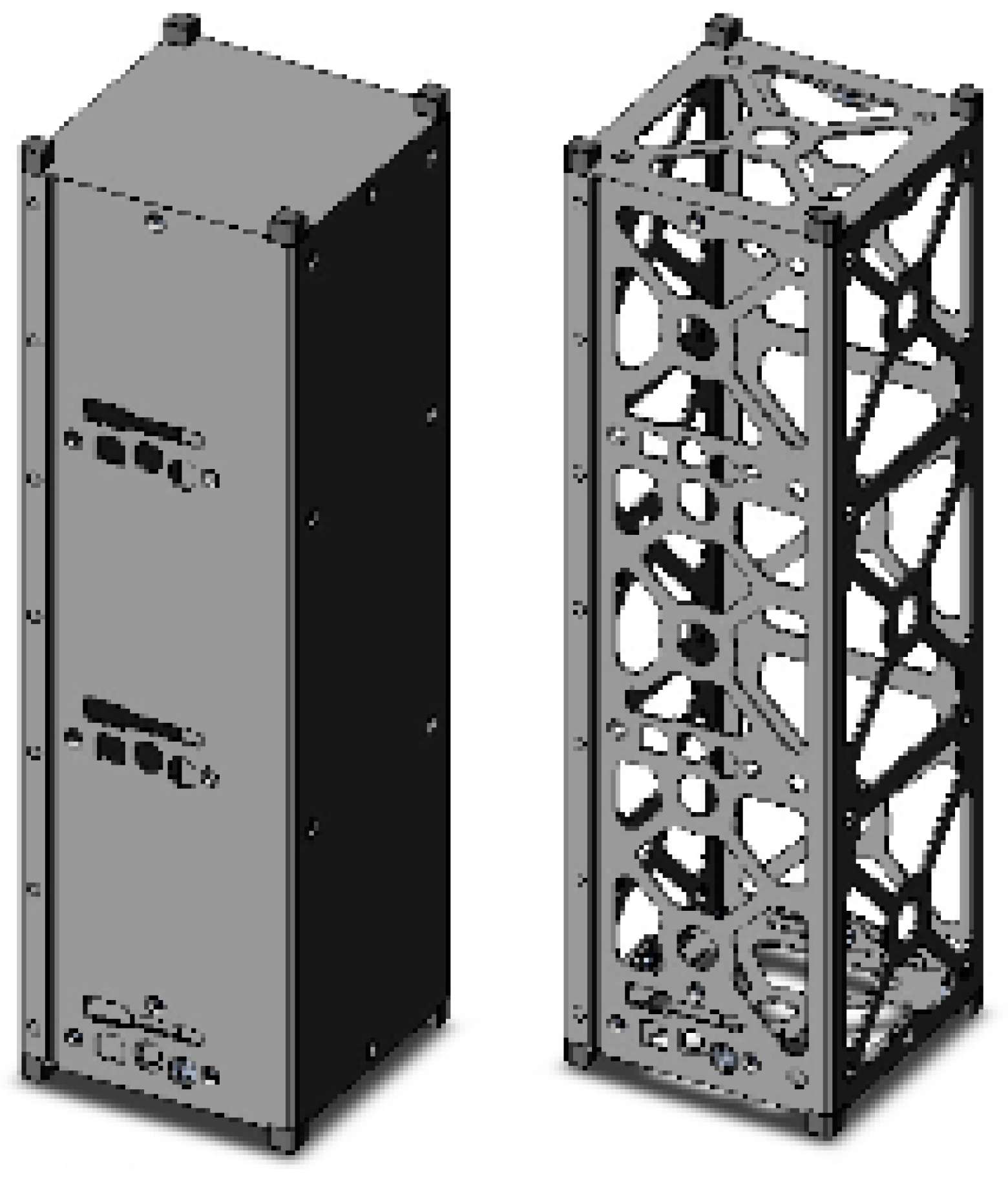
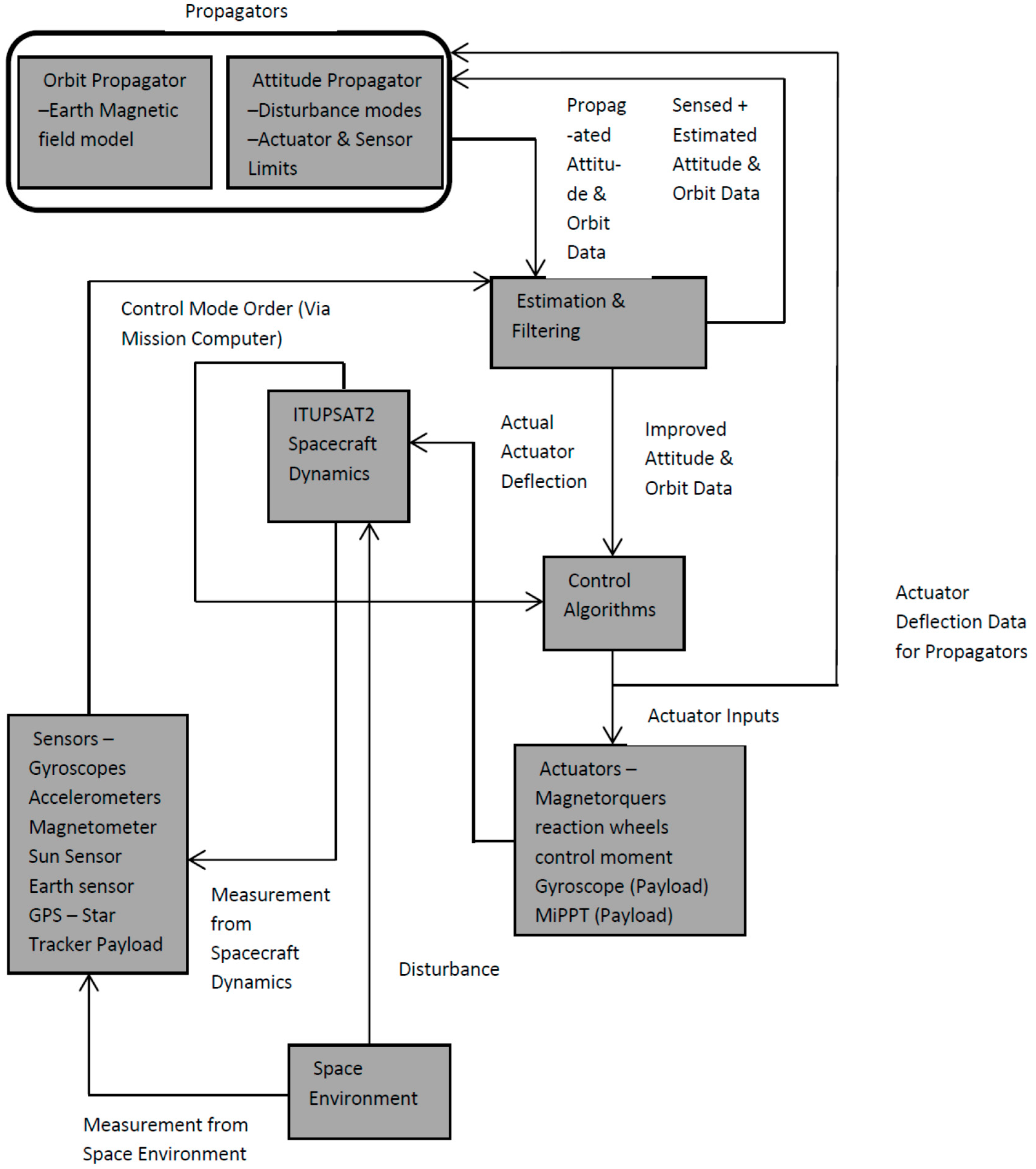
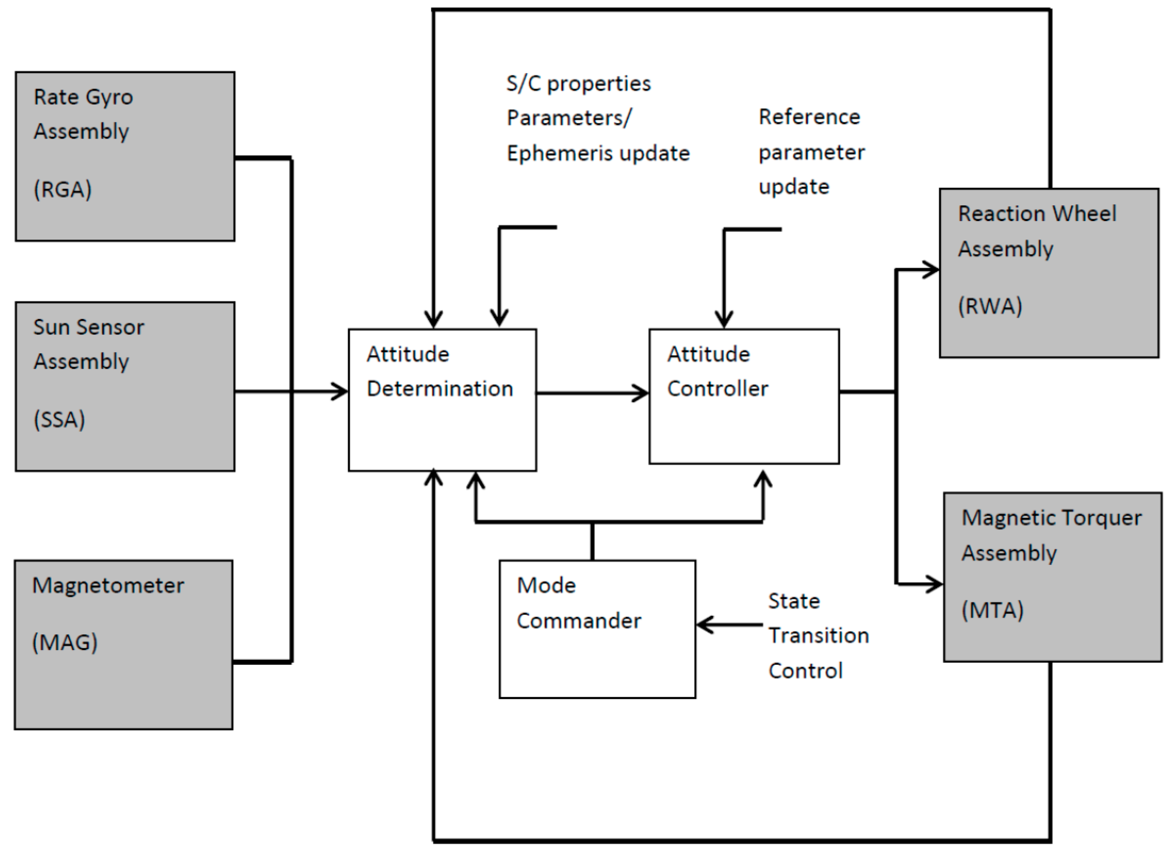
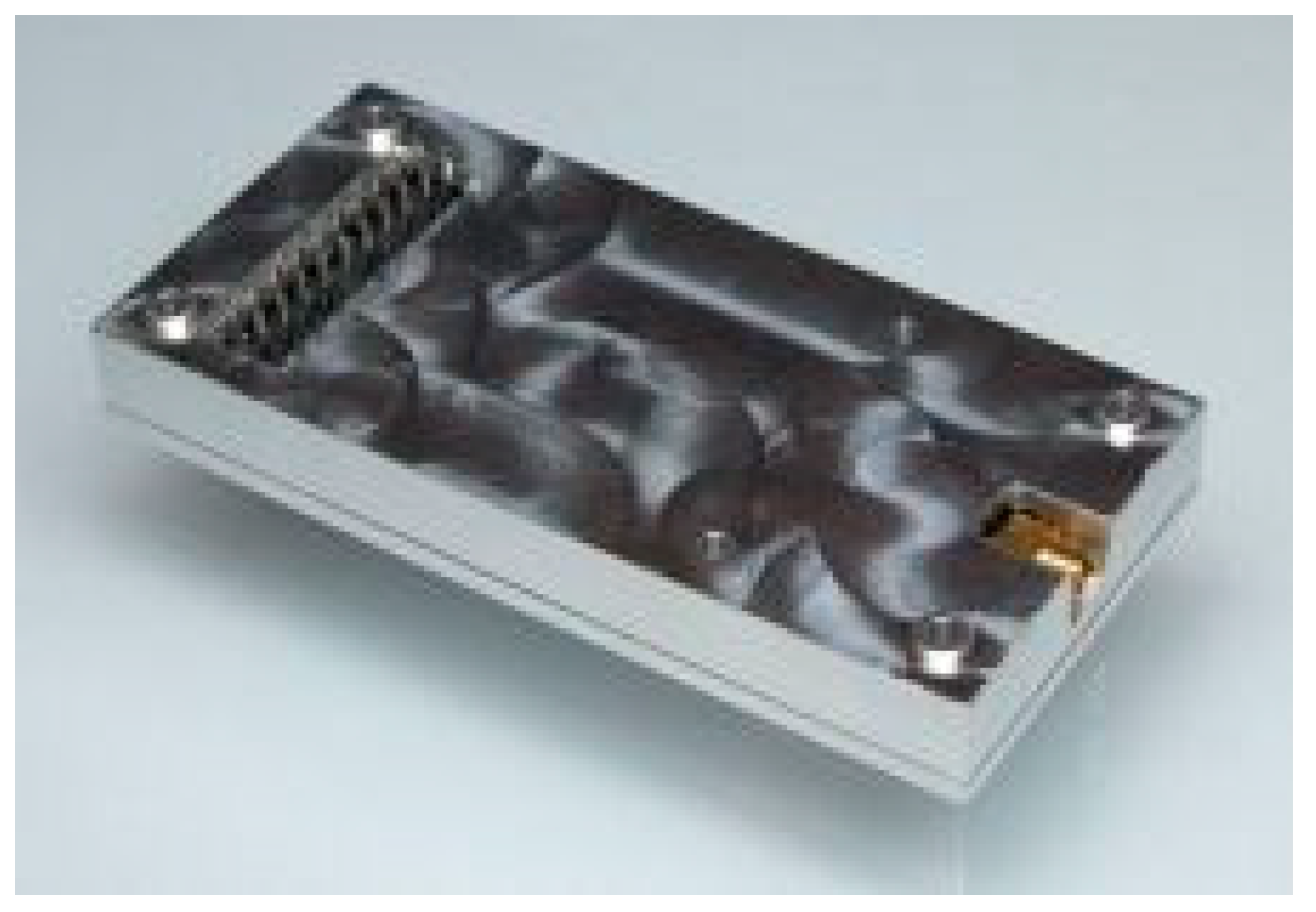
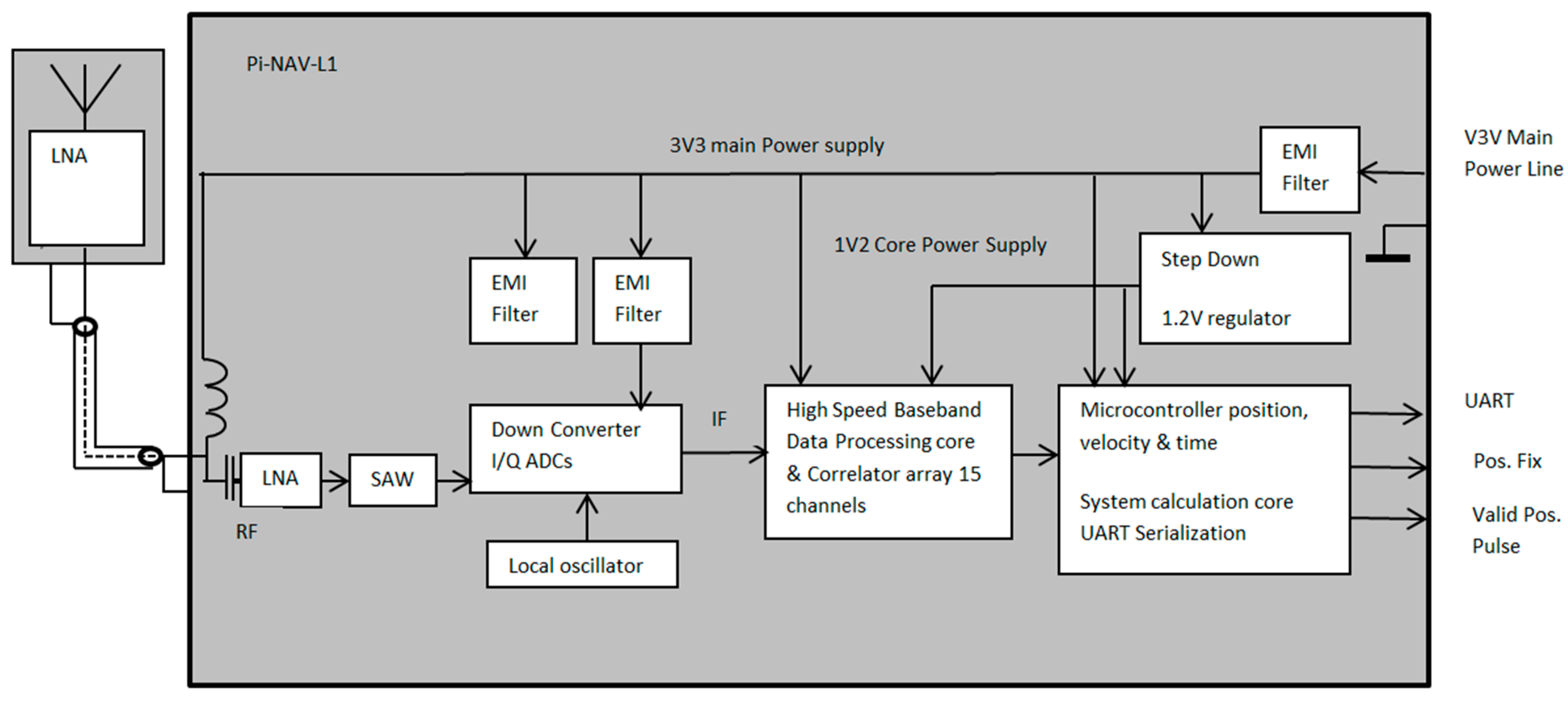
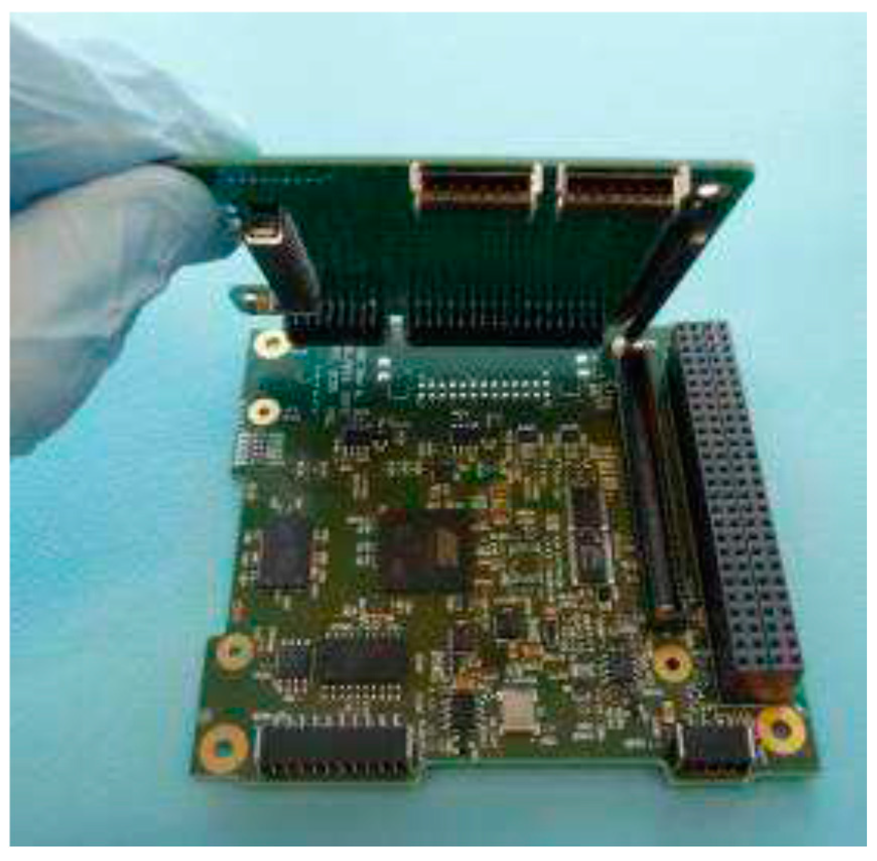
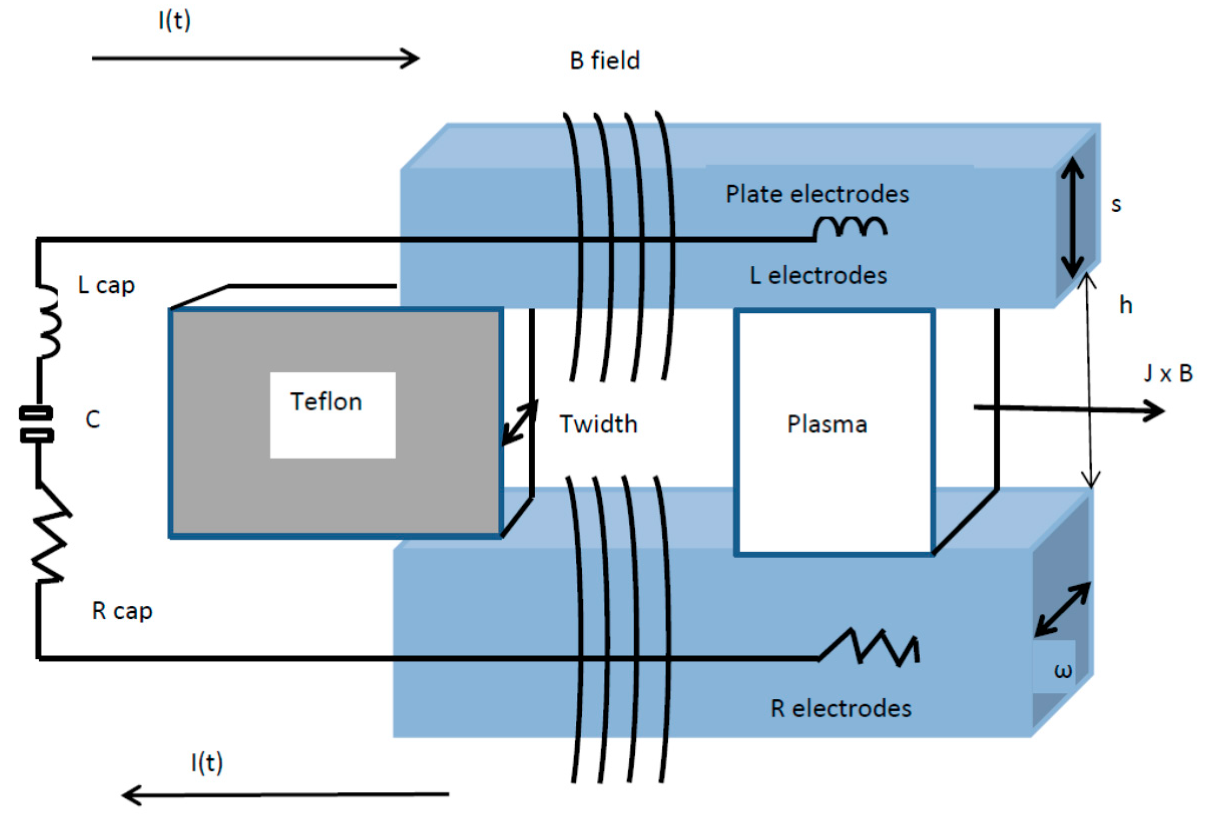
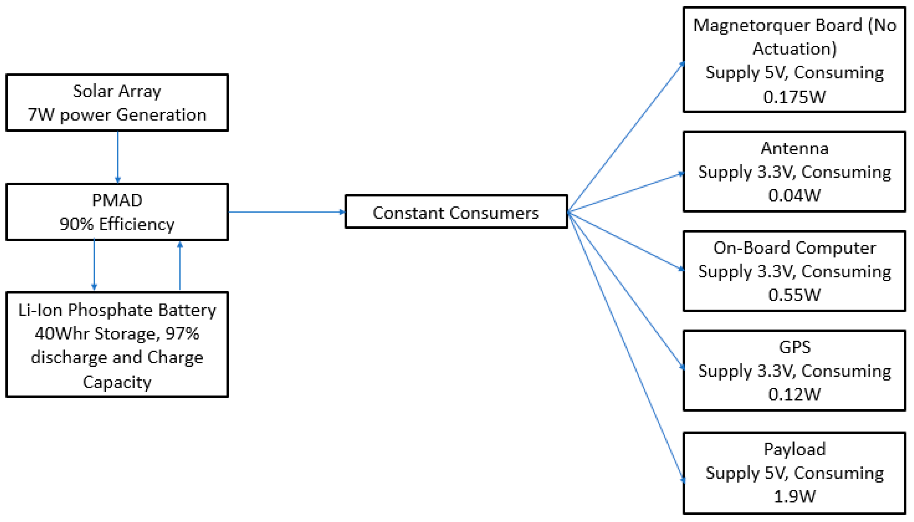
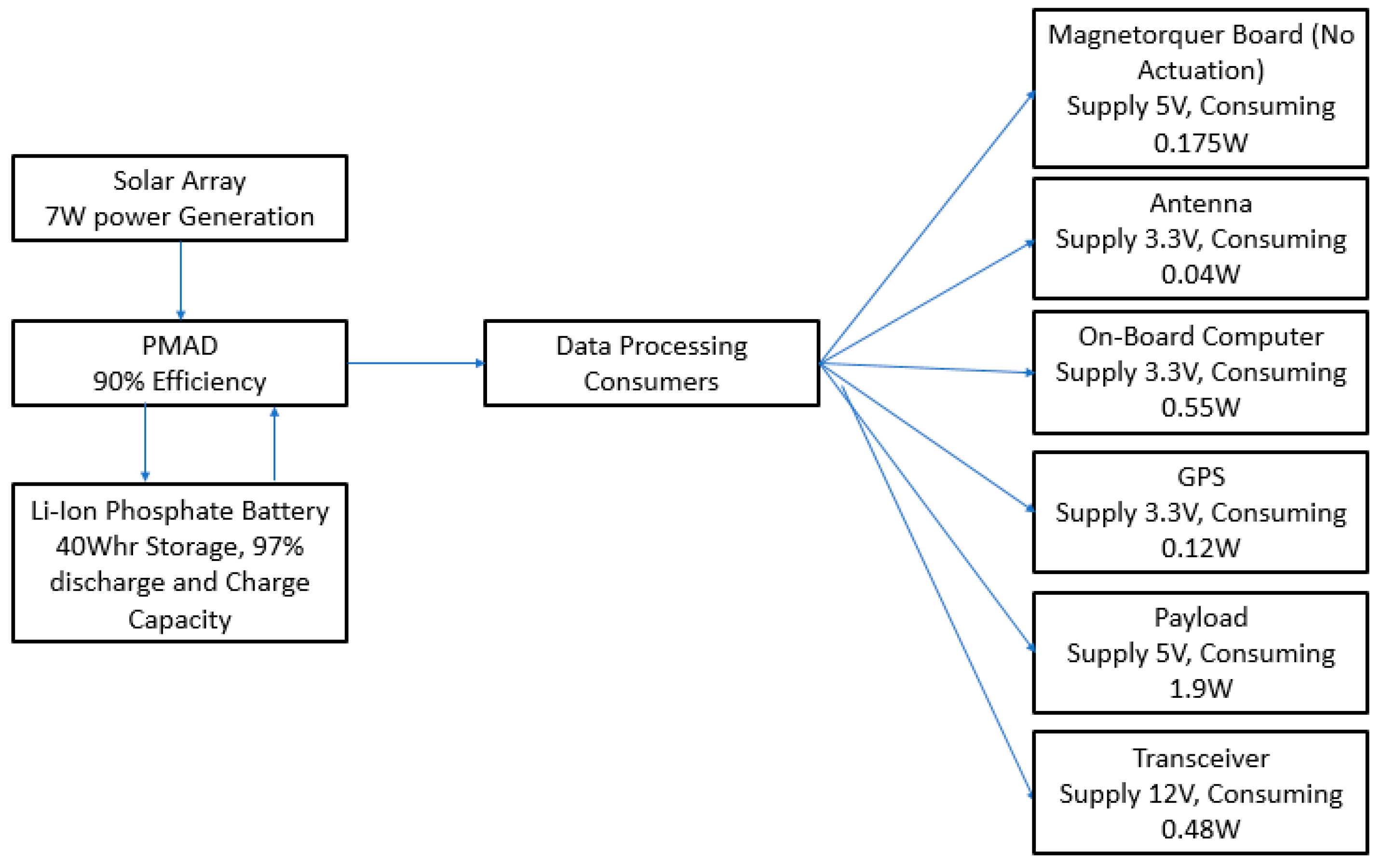
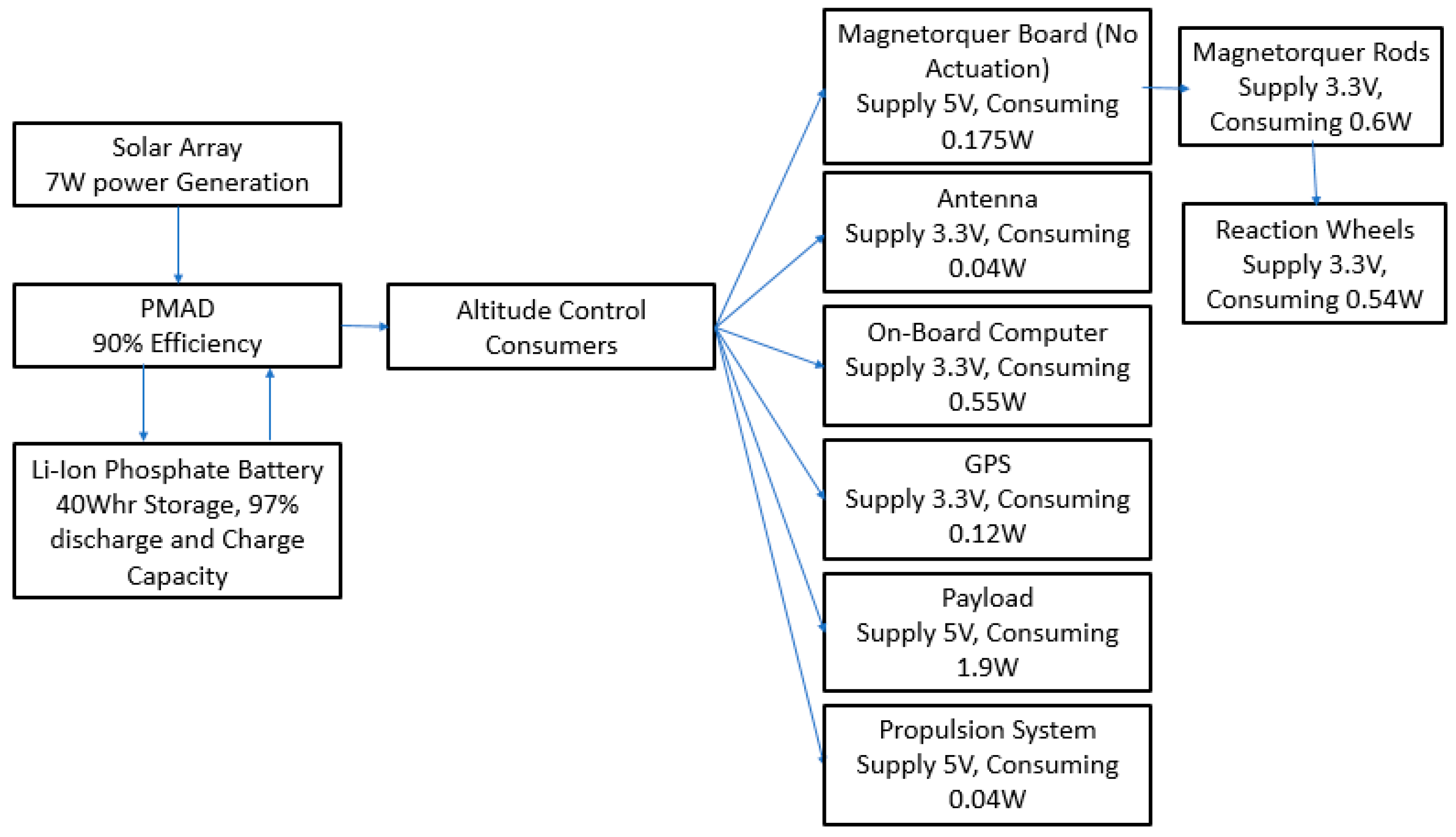
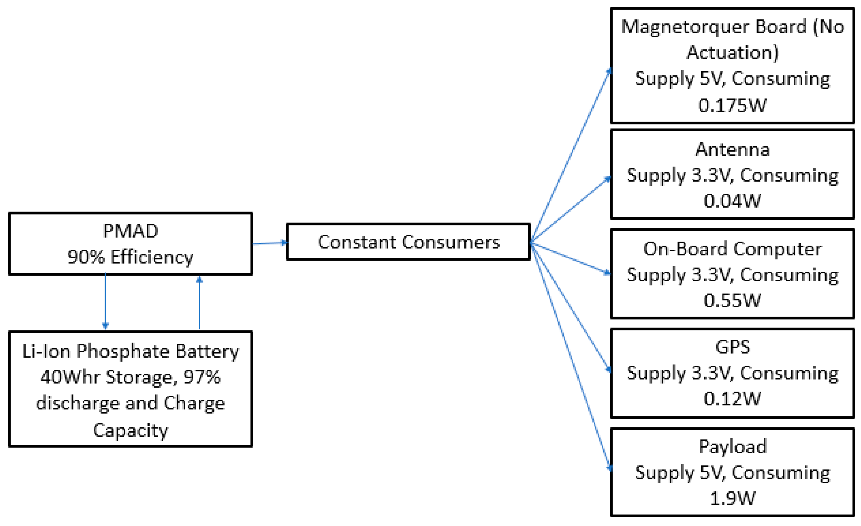
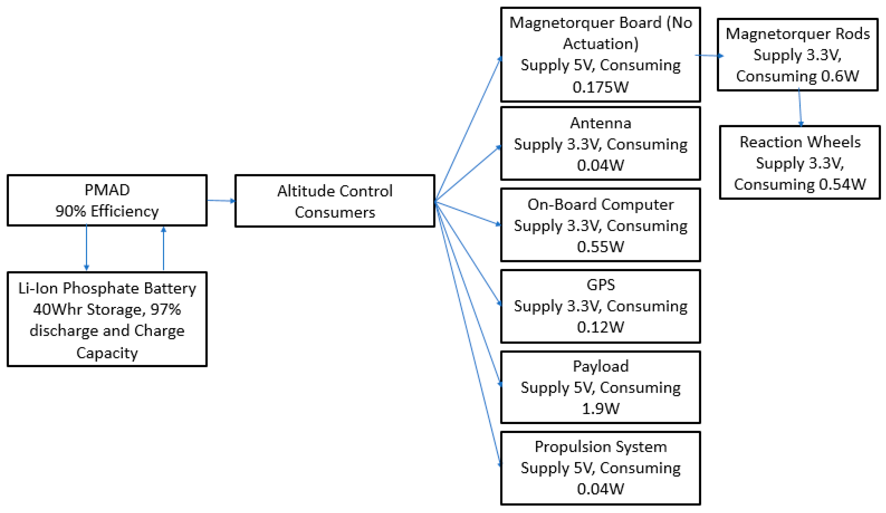
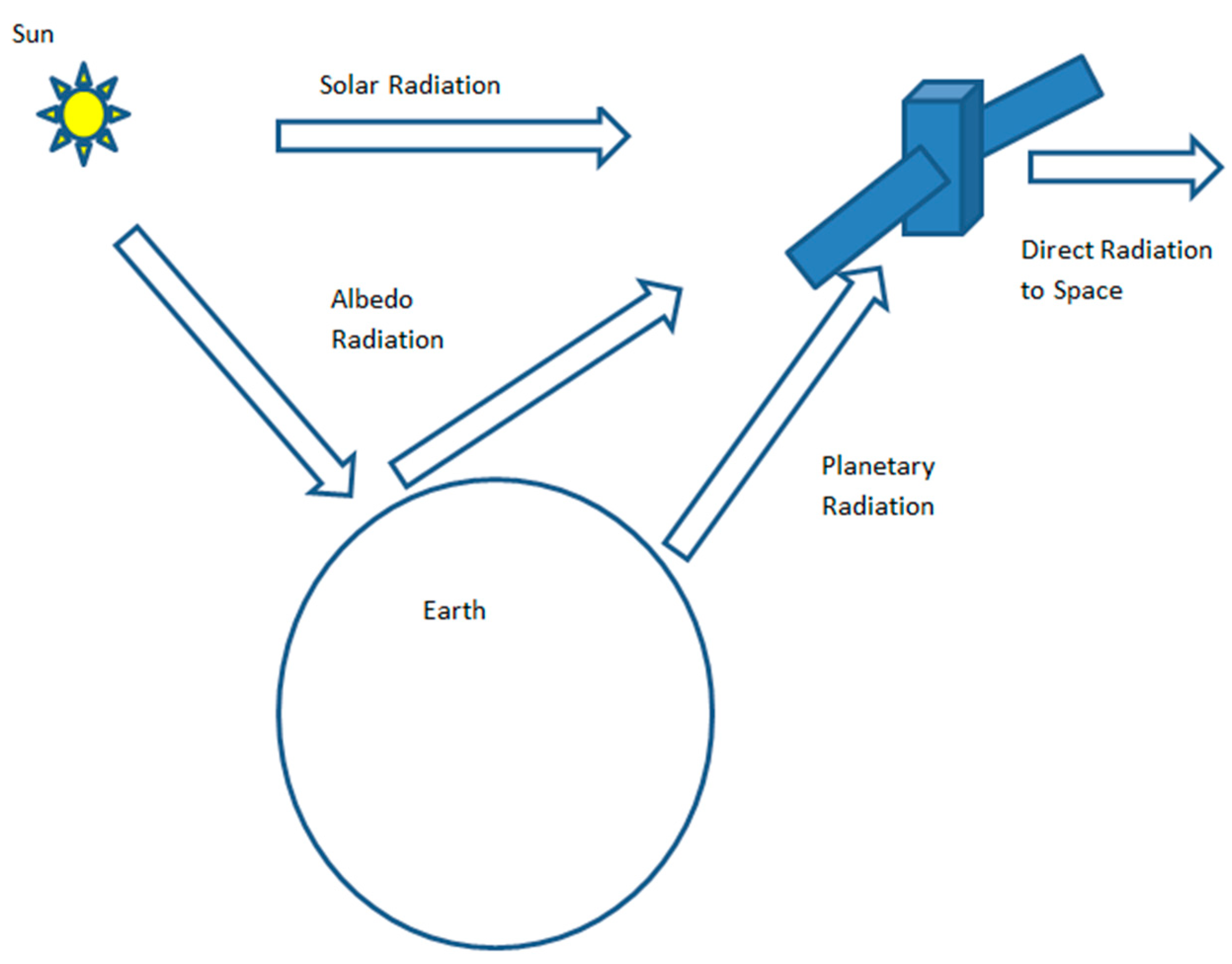
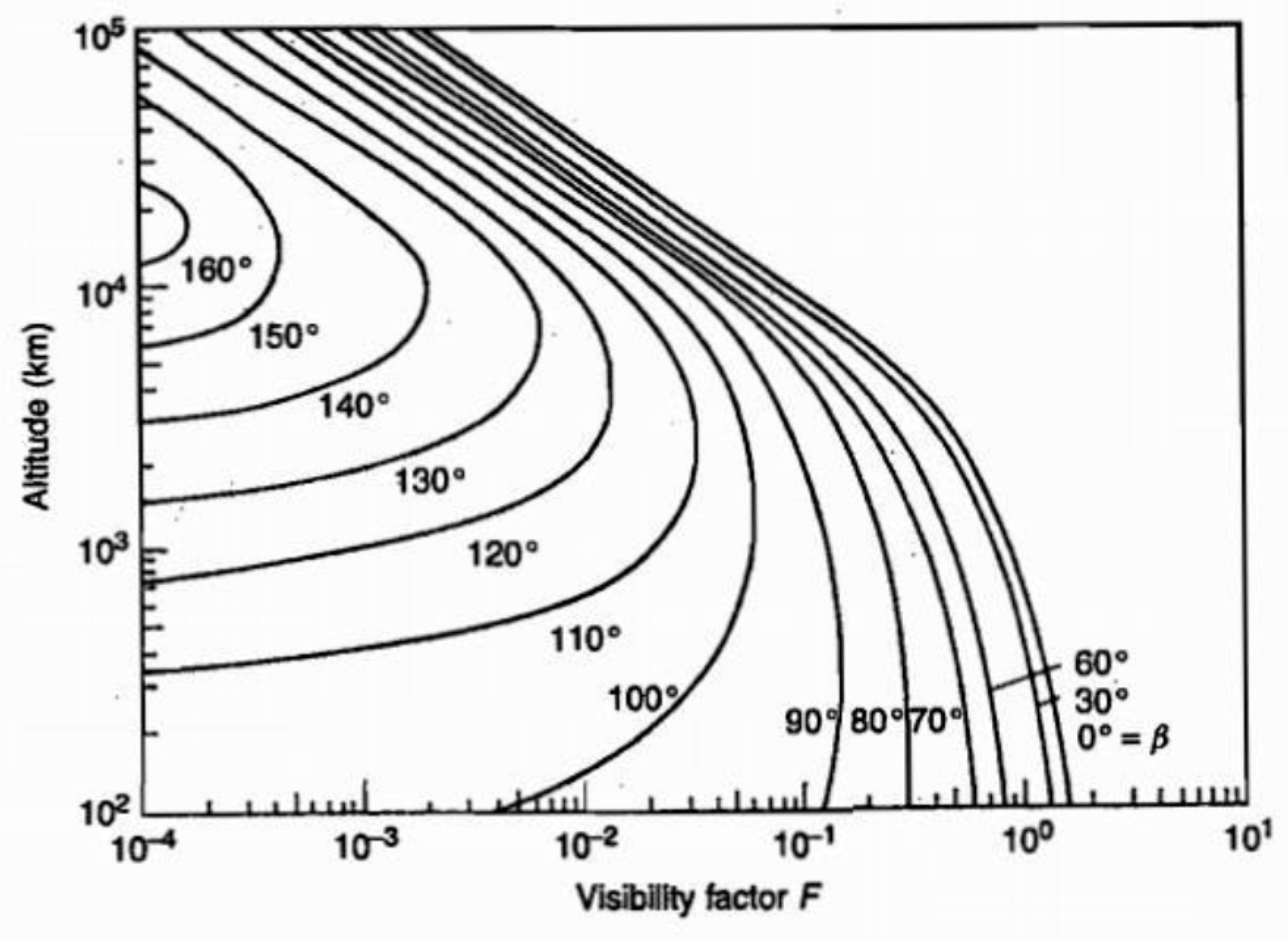
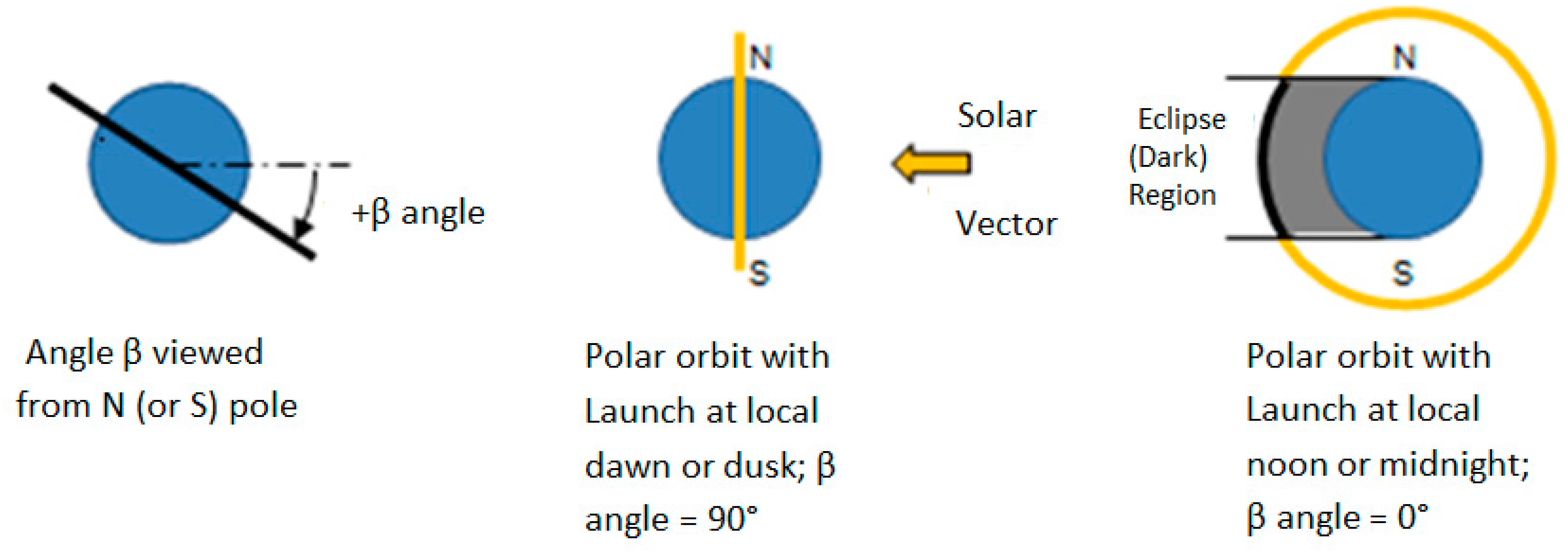
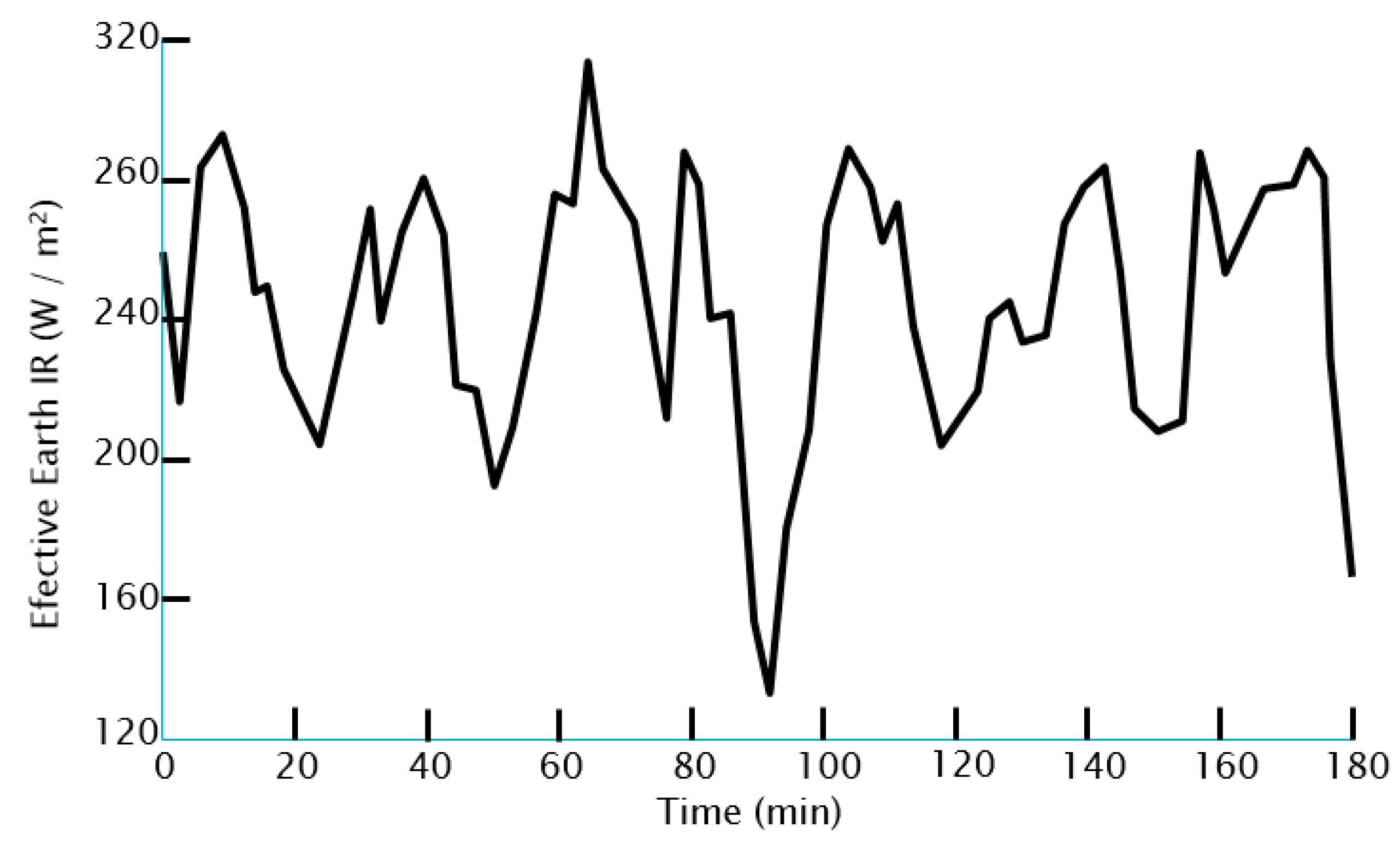
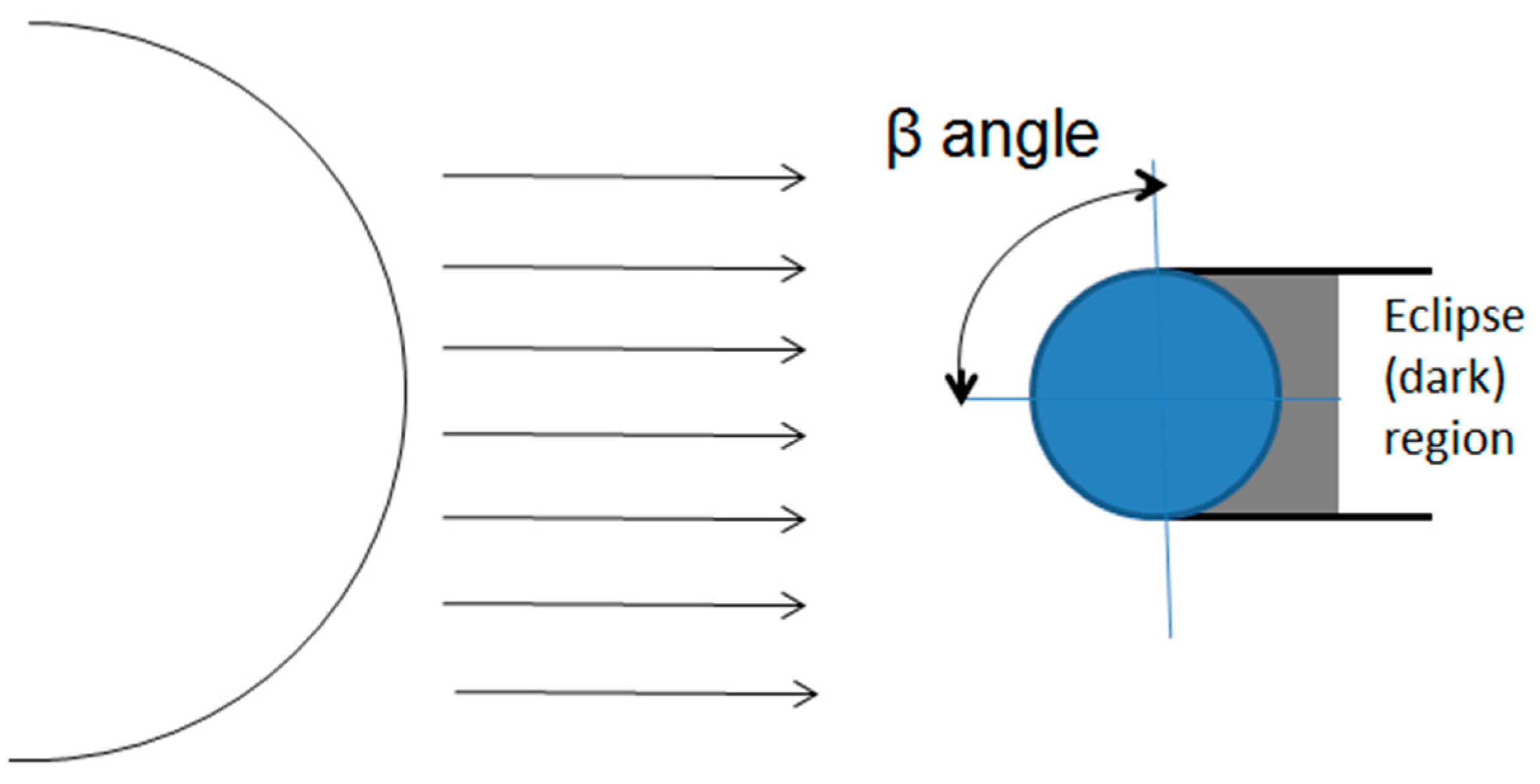
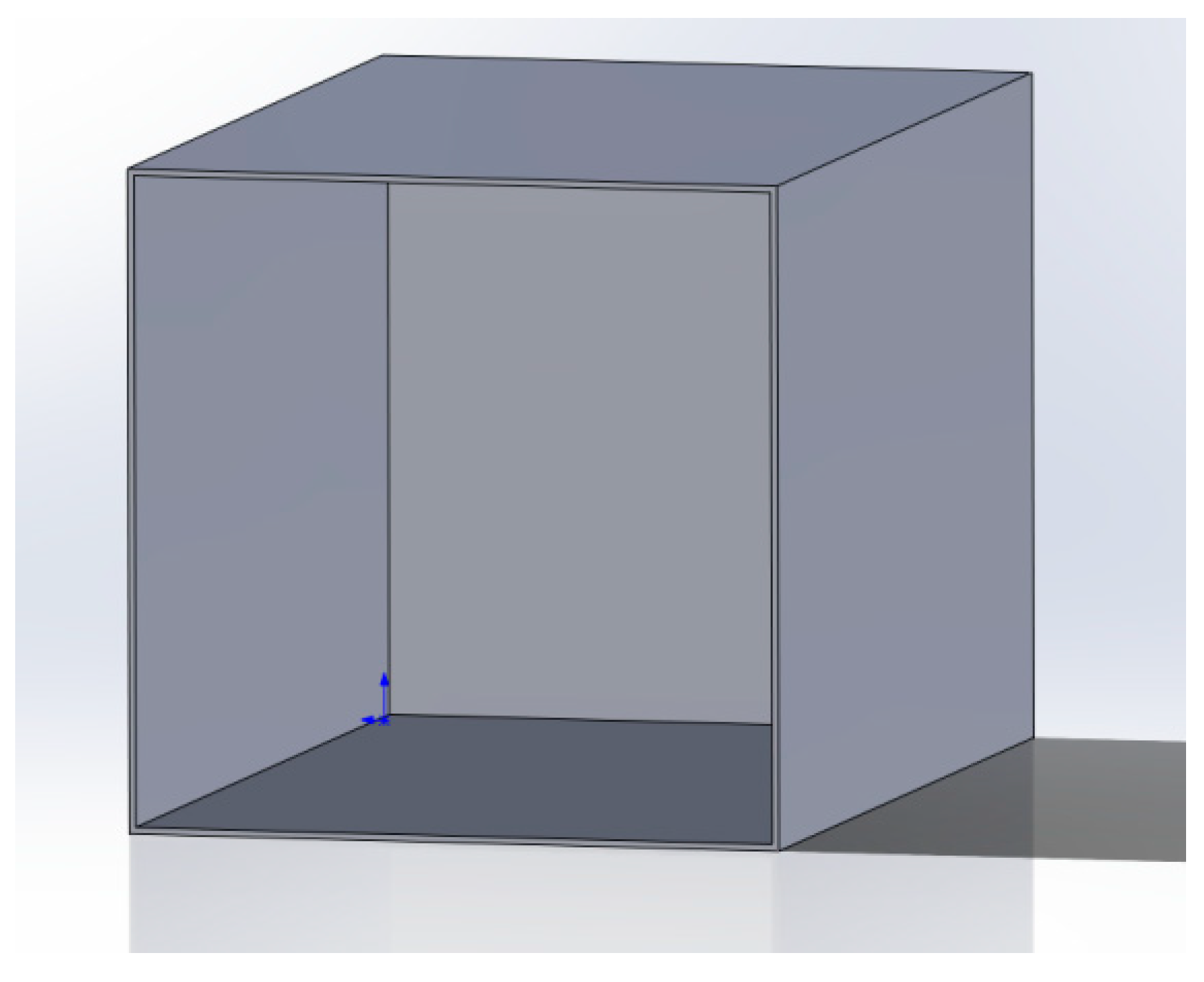
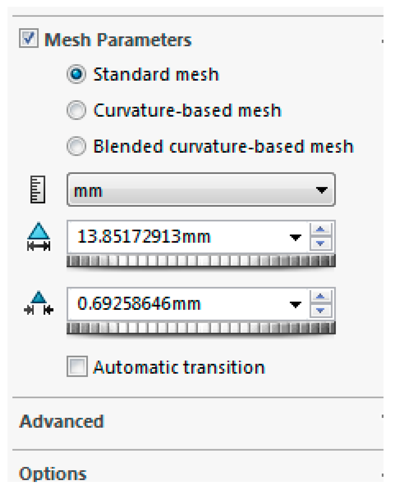
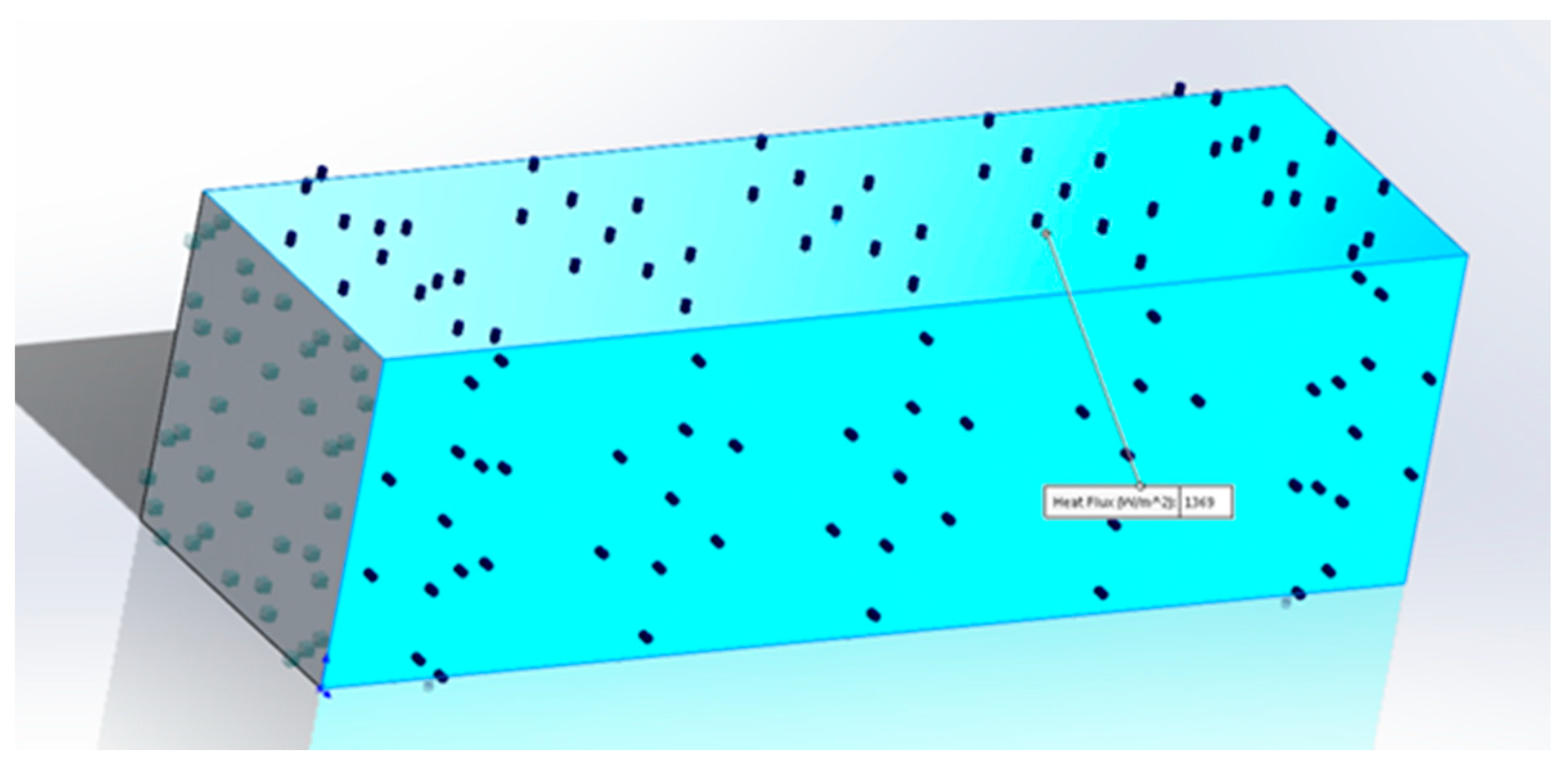
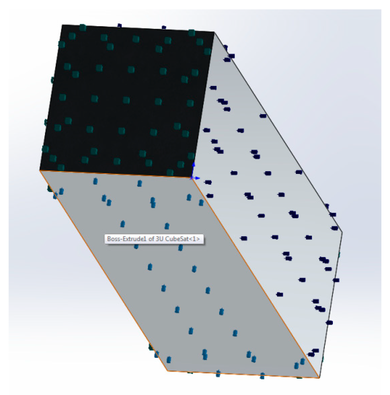
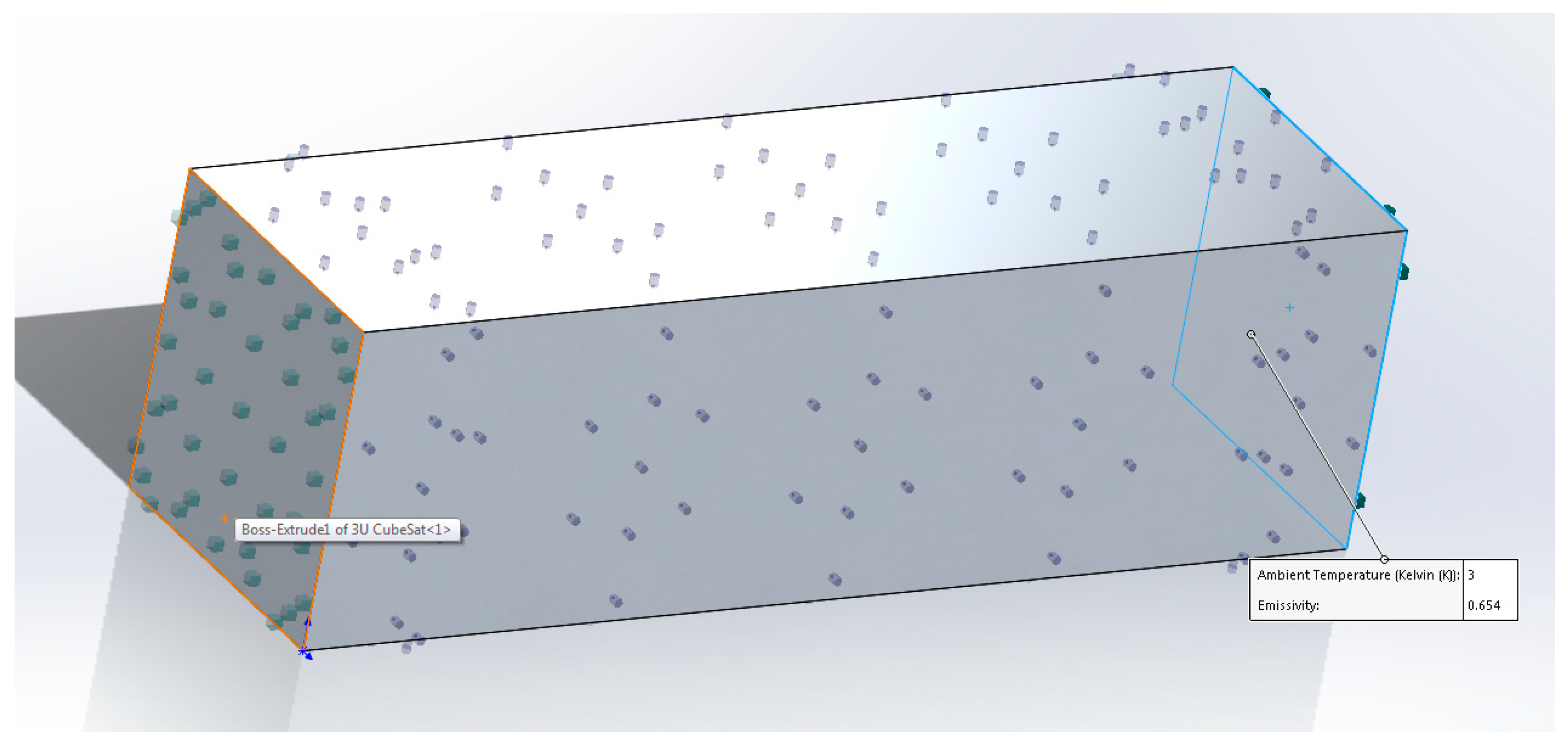
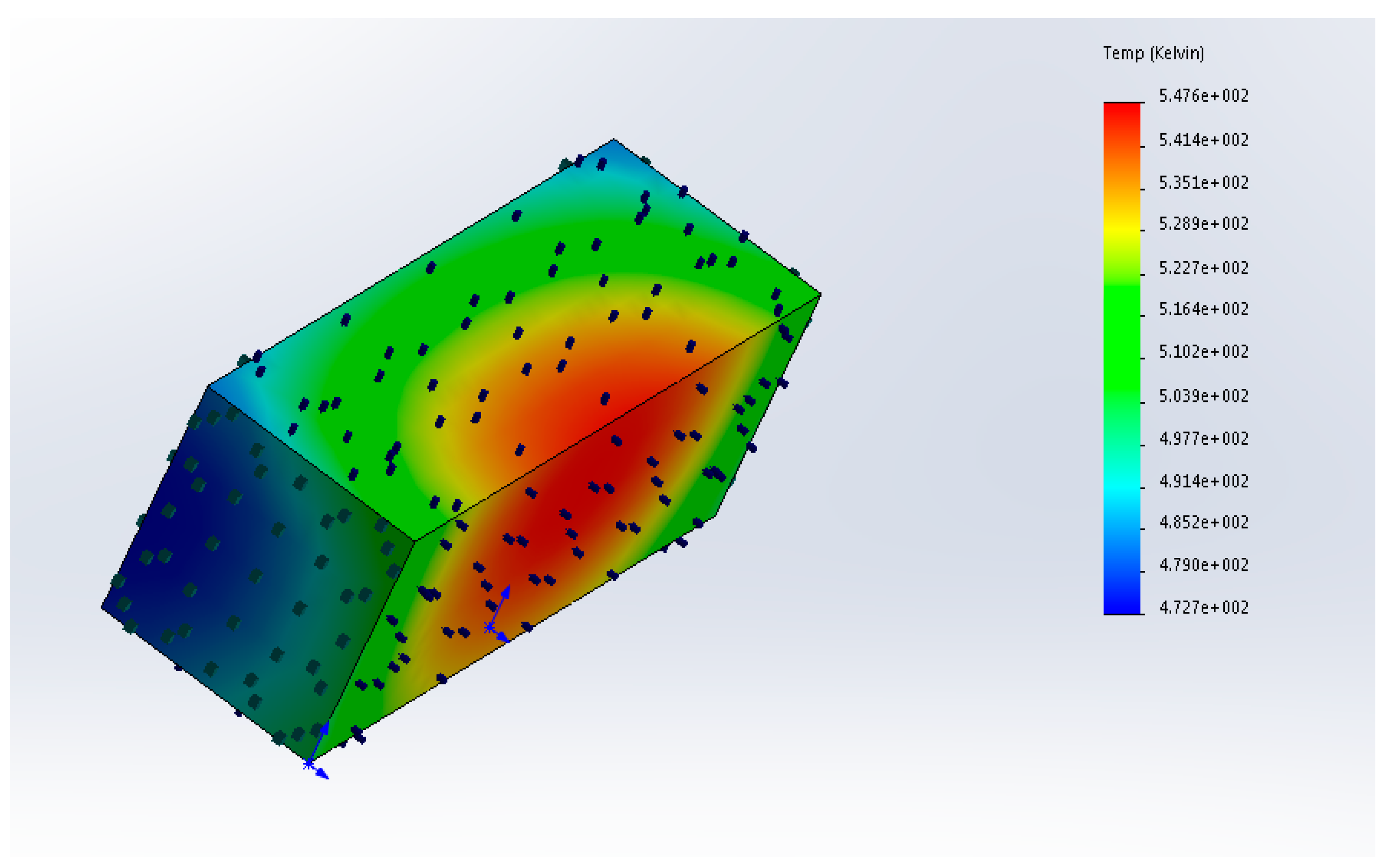
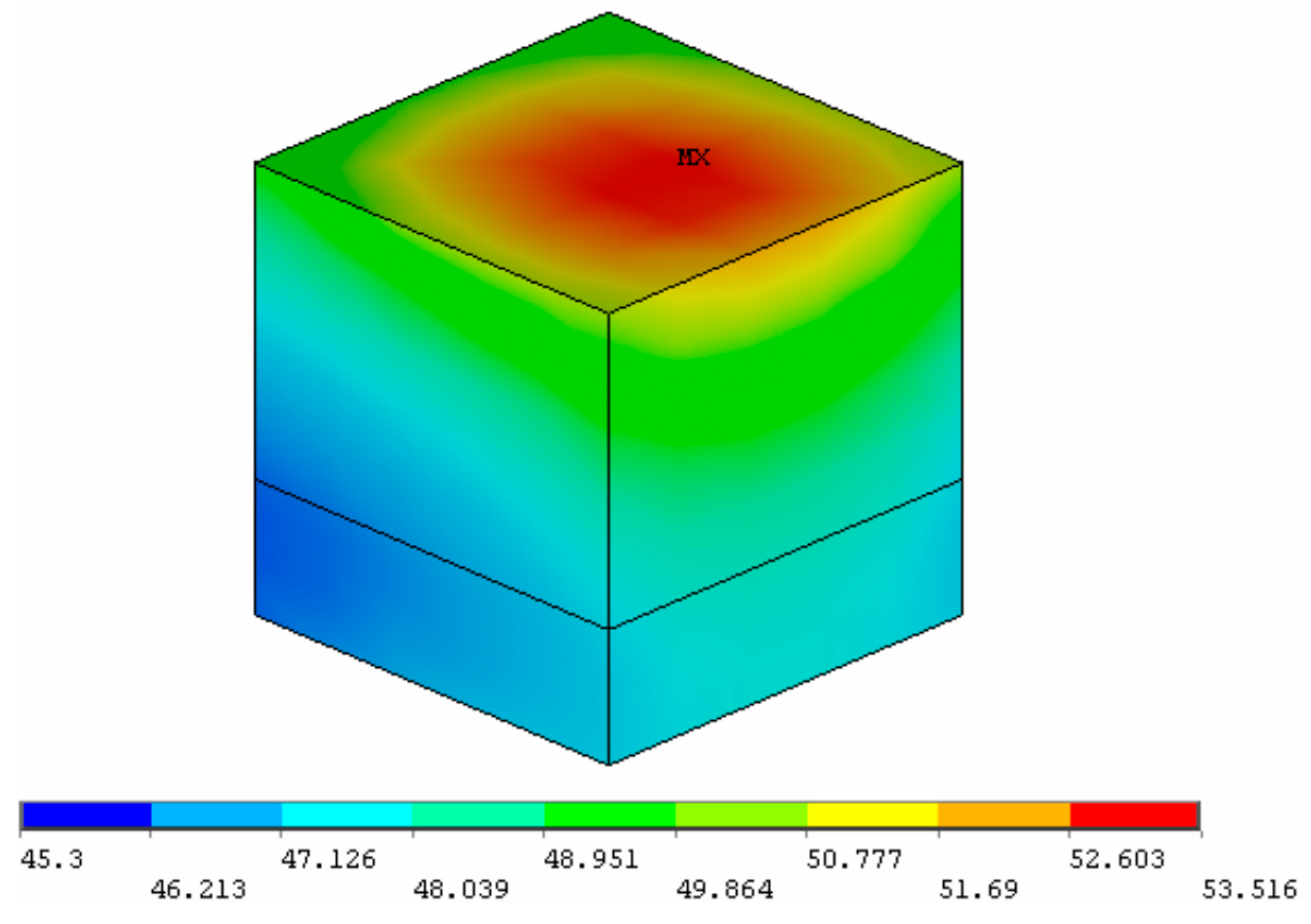
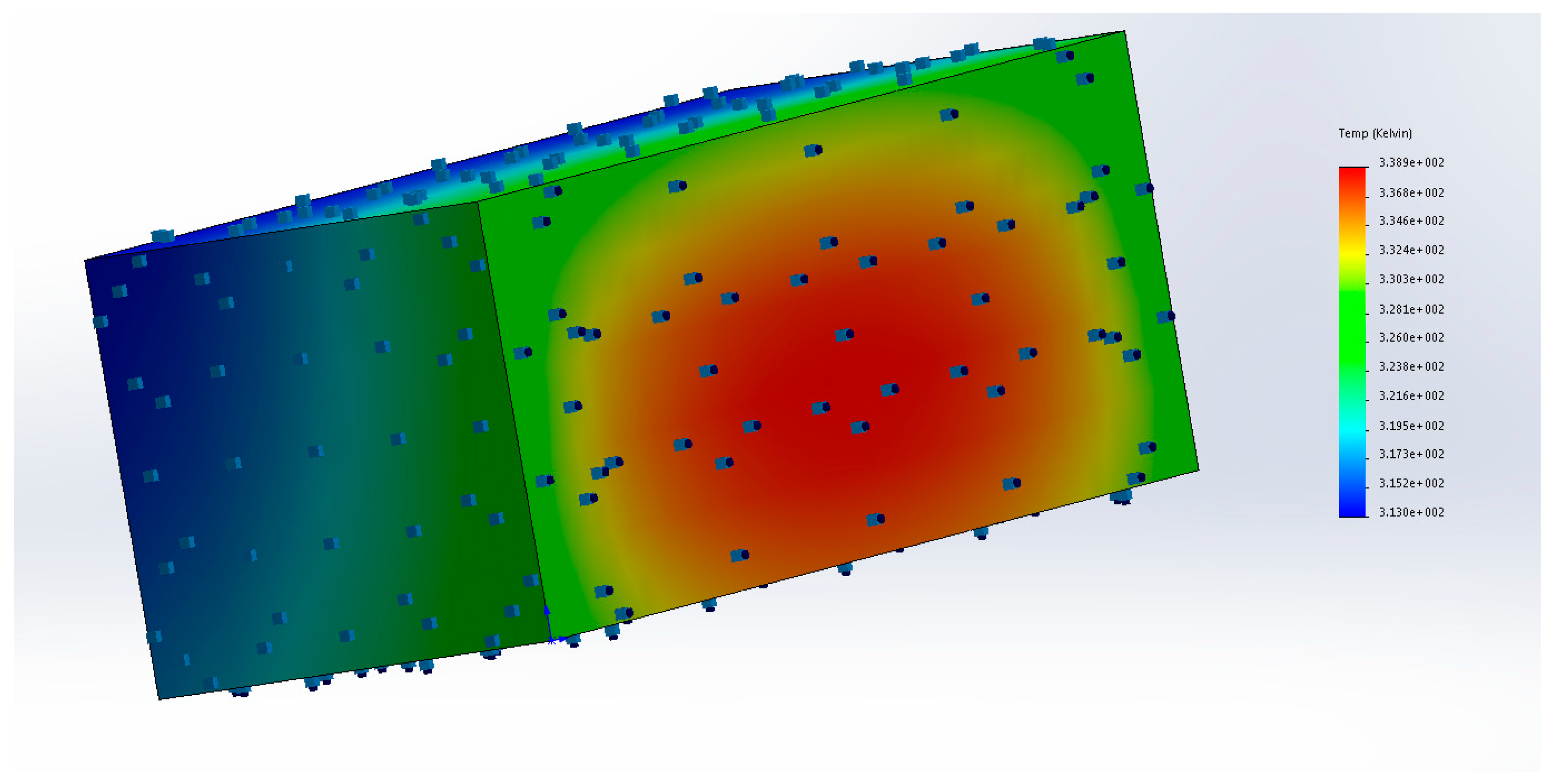
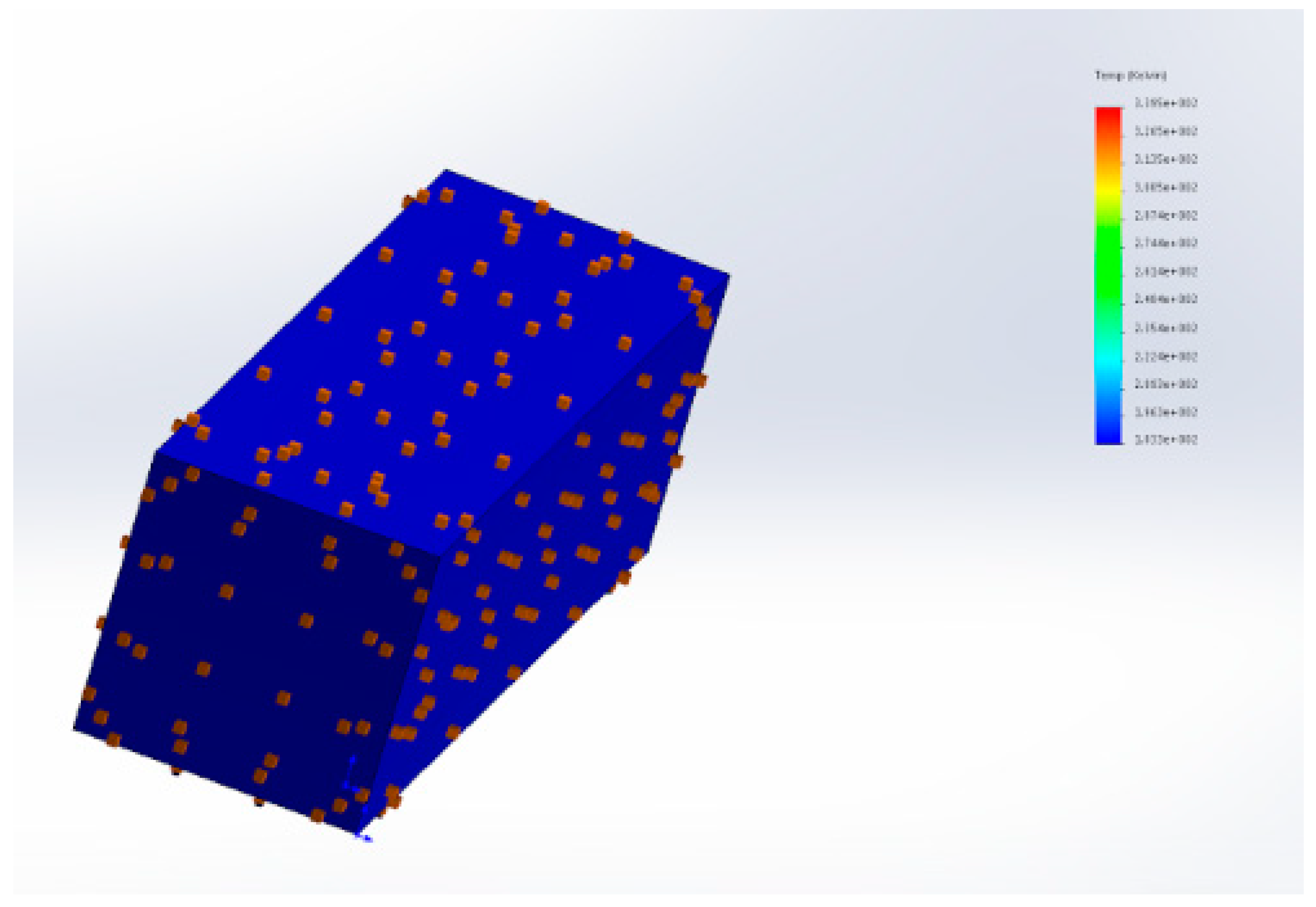
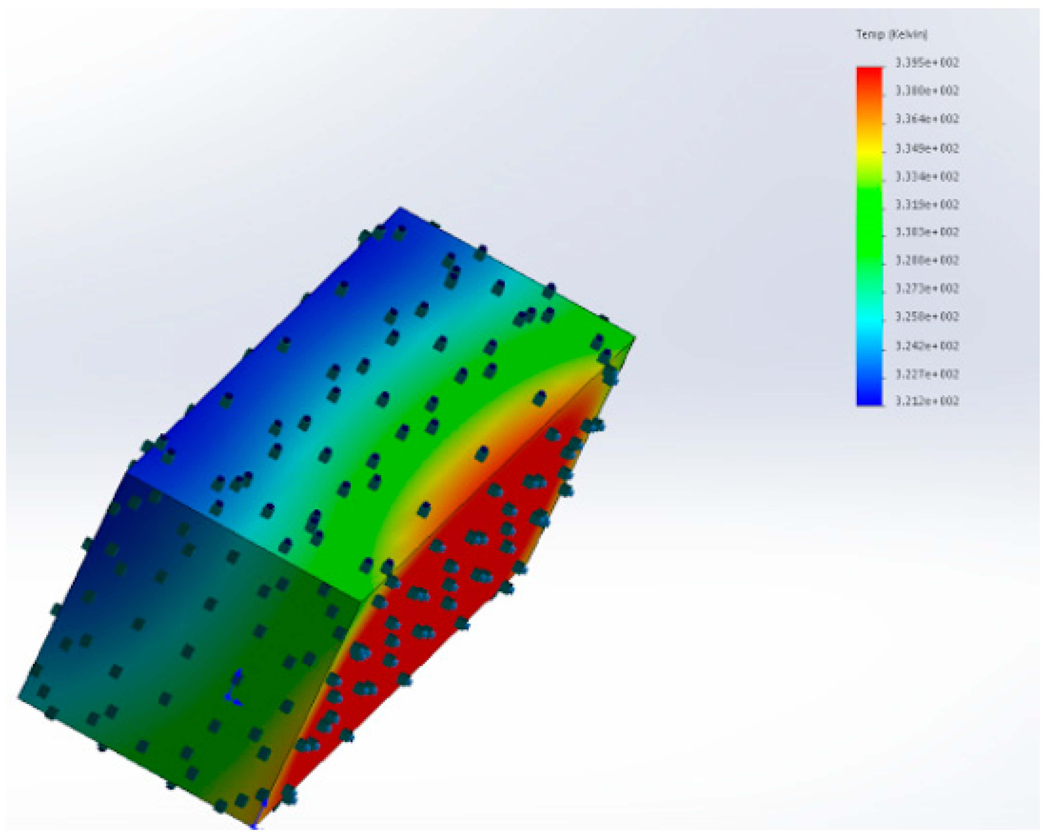
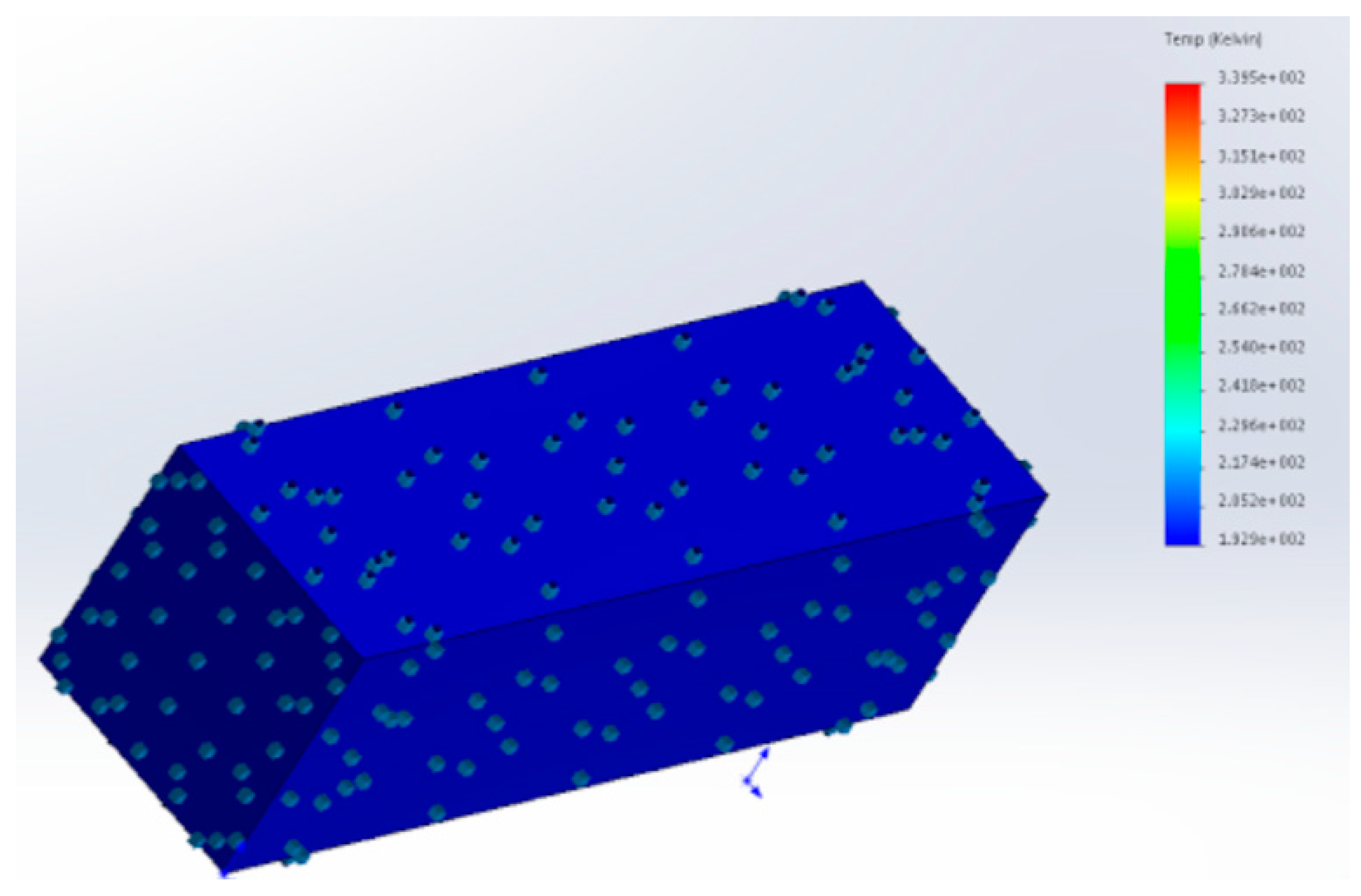
Table 1.
Summarizes the key numerical values presented in Section 2.4, Mission and Payload Specification.
Table 1.
Summarizes the key numerical values presented in Section 2.4, Mission and Payload Specification.
| Operational Requirement | Stated Value |
|---|---|
| Operational Altitude | Average 600 km, min value 550 km |
| Mission Duration | Minimum 6 Months–1 year |
| Payload Mass | 1 kg |
| Payload Power Draw | 1.9 W |
| Payload Dimensions | 100 × 100 × 100 mm (1U Dimensions) |
| Inclination | 98 degrees |
| β | 0 degrees |
Table 2.
Atmospheric Properties at a 600 km Altitude [10].
Table 2.
Atmospheric Properties at a 600 km Altitude [10].
| Property | Value at 600 km (Low Solar Activity) |
|---|---|
| Background Space Temperature | 3 K |
| Density | 1.03 × 10⁻¹⁴ kg/m3 |
| Pressure | 1.09 × 10⁻⁸ Pa |
| Molar Weight | 5.5149 kg/mol |
Table 3.
Atmospheric Properties at a 600 km Altitude with mean solar activity [10].
Table 3.
Atmospheric Properties at a 600 km Altitude with mean solar activity [10].
| Property | Value at 600 km (Mean Solar Activity) |
|---|---|
| Background Space Temperature | 3 K |
| Density | 1.56 × 10⁻¹³ kg/m3 |
| Pressure | 1.09 × 10⁻⁸ Pa |
| Molar Weight | 13.0389 kg/mol |
Table 4.
3U CubeSat Dimensions [1].
Table 4.
3U CubeSat Dimensions [1].
| CubeSat Size | 3U |
|---|---|
| X and Y Dimensions (mm) | 100 ± 0.1 |
| Z Dimension (mm) | 340.5 ± 0.3 |
| Rail Width (mm) | 8.5 by 8.5 (Minimum) |
| Rail Contact with P-POD (75% of Z Dimension, mm) | 255.4 (Minimum) |
| Component Protrusion Normal to CubeSat Surface (mm) | 6.5 (Maximum) |
| Mass (g) | 4000 (maximum) |
Table 5.
Propulsion Systems for Small Spacecraft [23].
Table 5.
Propulsion Systems for Small Spacecraft [23].
| Thruster Type | Average Thrust Output | Average Specific Impulse (s) | Status |
|---|---|---|---|
| Hydrazine | 0.5–4 N | 150–250 | TRL6 |
| Cold Gas | 10 mN–10 N | 65–70 | GN2/Butane TRL9 |
| Non-Toxic Propulsion | 0.1–27 N | 220–250 | HAN TRL8, ADN TRL6 |
| Pulsed Plasma and Vacuum arc | 1–15 mN | 500–3000 | Teflon TRL8, Titanium TRL7 |
| Electrospray | 10–120 µN | 500–5000 | TRL6 |
| Hall Effect | 10–50 mN | 1000–2000 | Xenon TRL8, Iodine TRL4 |
| Ion Engines | 1–10 mN | 1000–3500 | Xenon TRL8, Iodine TRL4 |
| Solar Sail | 0.25–0.6 mN | N/A | TRL6, TRL7 |
Table 6.
CHAMPS Performance Specification.
| Performance Criteria | CHAMPS Performance Per Thruster |
|---|---|
| Dimensions | 100 × 100 × 113.5 mm (1U) |
| Mass | 1.3 kg dry, 1.6 kg wet |
| Operating Temperature Range | 5–50 degrees Celsius |
| Power Consumption | 4 W Start-up, 1 W operation |
| Operational Voltage | 5 V Nominal |
| Thrust | 0.26–2.79 N |
| Minimum Impulse | 0.00484 s |
Table 7.
Cold and Warm Gas Propulsion Systems [23].
Table 7.
Cold and Warm Gas Propulsion Systems [23].
| Product | Manufacturer | Thrust | Specific Impulse | Propellant | Status |
|---|---|---|---|---|---|
| Micro-Thruster | Marotta, Montville, NJ, USA | 0.05–2.36 N | 65 s | Nitrogen | TRL9 |
| Butane | SSTL, Guildford, UK | 0.5 N | 80 s | Butane | TRL9 |
| MEMS | NanoSpace, Uppsala, Sweden | 0.01–1 mN | 50–75 s | Butane | TRL8 |
| POPSAT | MicroSpace, Singapore | 0.083–1.1 mN | 32–43 s | Argon | TRL8 |
| HIP1-CNAPS | UTIAS/SFL, Toronto, ON, Canada | 12.5–40 mN | 40 s | Sulphur Hexafluoride | TRL9 |
| CPOD | VACCO, South El Monte, CA, USA | 25 mN | 40 s | R134a | TRL6 |
Table 8.
Green Propellant Propulsion Systems (NASA, 2015) [23].
Table 8.
Green Propellant Propulsion Systems (NASA, 2015) [23].
| Product | Manufacturer | Thrust | Specific Impulse | Status |
|---|---|---|---|---|
| GR-1 | Aerojet Rocketdyne, Sacramento, CA, USA | 0.26–1.42 N | 231 s | TRL6 |
| GR-22 | Aerojet Rocketdyne, Sacramento, CA, USA | 5.7–26.9 N | 248 s | TRL5 |
| 1 N HPGP | ECAPS, Solna, Sweden | 0.25–1.00 N | 204–235 s | TRL8 |
| HYDROS | Tethers Inc., Bothel, WA, USA | 0.2–0.6 N | 258 s | TRL5 |
| BGT-X5 | Busek, Natick, MA, USA | 0.5 N | 220 s | TRL5 |
Table 9.
Solid Rocket Motor Performance [23].
Table 9.
Solid Rocket Motor Performance [23].
| Product | Manufacturer | Total Mass | Average Thrust | Specific Impulse | Status |
|---|---|---|---|---|---|
| ISP 30 Sec Motor | Industrial Solid Propulsion, Cedar City, UT, USA | 0.95 kg | 37 N | 187 s | TRL7 |
| STAR 4G | Orbital ATK, Dulles, VA, USA | 1.5 kg | 258 N | 277 s | TRL6 |
| CAPS-3 | DSSP, Reno, NV, USA | 2.33 kg | 0.3 N | 900 s | TRL8 |
Table 10.
Busek Ammonia Micro-Resistojet Performance [36].
Table 10.
Busek Ammonia Micro-Resistojet Performance [36].
| Performance Category | Achieved Value |
|---|---|
| Dimensions | 100 × 100 × 113.5 mm (1U) |
| Power Consumption | 15 W |
| Weight | 1.25 kg |
| Thrusts | 10 mN |
| ΔV (assuming 4 kg weight) | 60 m/s |
Table 11.
Electrospray Thruster Performance data [23].
Table 11.
Electrospray Thruster Performance data [23].
| Product | Manufacturer | Thrust | Power | Specific Impulse | Status |
|---|---|---|---|---|---|
| S-iEPS | MIT, Cambridge, MA, USA | 74 µN | 1.5 W | 1160 s | TRL6 |
| IMPACT | Accion Systems Inc., Boston, MA, USA | 60 µN | 0.75 W | 1200 s | TRL5 |
| MAX-1 | Accion Systems Inc., Boston, MA, USA | 120 µN | 1.6 W | 2000 s | TRL5 |
| 1 mN Electrospray | Busek, Natick, MA, USA | 0.7 mN | 15 W | 800 s | TRL5 |
| 100 µN Electrospray | Busek, Natick, MA, USA | 0.1 mN | 5 W | 2300 s | TRL5 |
| Product | Manufacturer | Thrust | Power | Specific Impulse | Propellant | Status |
|---|---|---|---|---|---|---|
| PPTCUP | Mars Space, Southampton, UK, and Clyde Space, Glasgow, UK | 40 µN | 2 W | 655 s | PTFE | TRL6 |
| NanoSat PPT | Mars Space and Clyde Space | 90 µN | 5 W | 640 s | PTFE | TRL5 |
| µCAT | GWU, Washington, DC, USA, and USNA, Annapolis, MD, USA | 1–50 µN | 2–14 W | 2500–3000 s | Titanium | TRL7 |
| BmP-220 | Busek | 20 µN-s | 1.5 W | 536 s | PTFE | TRL5 |
| MPACS | Busek | 80 µN-s | 10 W | 827 s | PTFE | TRL8 |
| P4 RFT | Phase Four, El Segundo, CA, USA | 1–15 mN | 3 W | 500–1000 s | PTFE | TRL9 |
Table 13.
Radio Frequency Operating Bands [23].
Table 13.
Radio Frequency Operating Bands [23].
| Radio Band | Operating Frequency |
|---|---|
| Very High-Frequency (VHF) | 30 to 300 MHz |
| Ultra High-Frequency (UHF) | 300 MHz to 3 GHz |
| L | 1 to 2 GHz |
| S | 2 to 4 GHz |
| C | 4 to 8 GHz |
| X | 8 to 12 GHz |
| Optical Laser Communication | 100 to 800 THz |
Table 14.
Typically, Implemented Guidance, Control, and Navigation Technologies [23].
Table 14.
Typically, Implemented Guidance, Control, and Navigation Technologies [23].
| Subsystem | Performance |
|---|---|
| Reaction Wheels | 0.1 Nm Peak Torque, 1.5 N m s storage |
| Magnetorquers | 5 A m2 Peak Dipole |
| Star Trackers | 25 arcsec pointing Knowledge |
| Sun Sensors | 0.1 deg accuracy |
| Earth Sensors | 0.25 deg accuracy |
| Gyroscopes | 1 deg h−1 bias stability, 0.1 deg h−1/2 Random walk |
| GPS Receivers | 1.5 m position accuracy |
| Integrated Unites | 0.007 deg pointing capability |
Table 15.
Small Space Craft Reaction Wheel Performance Data [23].
Table 15.
Small Space Craft Reaction Wheel Performance Data [23].
| Product | Manufacturer | Mass (kg) | Peak Torque (N m) | Momentum Capacity (N m s) | Radiation Tolerance (Krad) | Status |
|---|---|---|---|---|---|---|
| 10SP-M | Surry Satellite Technology, Guildford, UK | 0.96 | 0.011 | 0.42 | 5 | TRL9 |
| 100SP-O | Surry Satellite Technology | 2.6 | 0.11 | 1.5 | 5 | TRL9 |
| RW-0.03 | Sinclair Interplanetary, Toronto, ON, Canada | 0.185 | 0.002 | 0.04 | 20 | TRL9 |
| Performance Criteria | Delivered Performance |
|---|---|
| Magnetic Moment | >0.2 A m2 |
| Linearity | ±5% across operating design range |
| Residual Moment | <0.001 A m2 |
| Operating Temperature Range | −35 °C to +75 °C |
| Power Draw | 200 mW from 5 V supply |
| Random Vibration | 14 g rms |
| Mass | 30 g |
| Dimensions | 70 mm length × 9 mm Diameter |
| Lifetime | 10 years |
Table 17.
Magnetorquer Performance Data [23].
Table 17.
Magnetorquer Performance Data [23].
| Product | Manufacturer | Mass (kg) | Peak Dipole (A m2) | Radiation Tolerance (Krad) | Status |
|---|---|---|---|---|---|
| MTR-5 | Surry Satellite Technology | 0.5 | 5 | 5 | TRL9 |
| MT0.1-1 | ZARM, Bremen, Germany | 0.060 | 1 | 5 | TRL9 |
| TQ-15-28-0-1-1 | Space Flight Industries, Seattle, WA, USA | 0.727 | 15 | 5 | TRL9 |
| Product | Manufacturer | Mass (kg) | Resolution | Orthogonality | Radiation Tolerance (Krad) | Status |
|---|---|---|---|---|---|---|
| Magnetometer | New Space Systems, Somerset West, South Africa | 0.2 | 6.5 nT | <1 deg | 10 | TRL9 |
| MicroMag3 | PNI Corp, Santa Rosa, CA, USA | 0.2 | 15 nT | <1 deg | 10 | TRL9 |
| Magnetometer | Surry Satellite Technology | 0.19 | 10 nT | <1 deg | 5 (Si) | TRL9 |
Table 19.
Sun Sensor Performance Data [23].
Table 19.
Sun Sensor Performance Data [23].
| Product | Manufacturer | Mass (kg) | Accuracy | Radiation Tolerance (Krad) | Status |
|---|---|---|---|---|---|
| Fine (Digital) Sun Sensor | New Space System | 0.035 | 0.1 deg | 10 | TRL9 |
| Analog Sun Detector | Adcole, Marlborough, MA, USA | 0.068 | 0.75 deg | 10 | TRL9 |
| CSS-01 | Space Micro, San Diego, CA, USA | 0.0414 | 5 deg | 10 | TRL9 |
Table 20.
Earth Sensor Performance Data [23].
Table 20.
Earth Sensor Performance Data [23].
| Product | Manufacturer | Mass (kg) | Accuracy | Status |
|---|---|---|---|---|
| Static Earth Sensor | Maryland Aerospace, Crofton, MD, USA | 0.033 | 0.25 deg | TRL9 |
| Mini Digital HCI | Servo, Westbury, NY, USA | 0.050 | 0.75 deg | TRL9 |
Table 21.
Gyroscope Performance Data [23].
Table 21.
Gyroscope Performance Data [23].
| Product | Manufacturer | Type | Mass (kg) | Bias Stability | Random Walk | Radiation Tolerance (Krad) | Status |
|---|---|---|---|---|---|---|---|
| MIRAS-01 | Surry Satellite Technology | 3 axis MEMS | 2.8 | 10 deg h−1 | 0.6 deg h−1/2 | 5 | TRL9 |
| LN200-S | Northrop Grumman, Dulles, VA, USA | 3 axis FOG | 0.75 | 1 deg h−1 | 0.1 deg h−1/2 | 10 | TRL9 |
| ADIS16405 | Analog Devices, Norwood, MA, USA | 3 axis MEMS | 0.016 | 25 deg h−1 | 2.0 deg h−1/2 | 10 | TRL9 |
Table 22.
3U CubeSat Product Design Specification.
| Component System Category | Sub-Category | Specification | Suggested Component | Wish/Demand |
|---|---|---|---|---|
| Structure | Dimensions | The structure must conform to the CubeSat Specification | 100 × 100 × 340 mm | D |
| Mass | The mass should aim to be as low as possible to ensure the CubeSat does not exceed 4 kg | 0.5 kg | W | |
| Construction | Part must easily assemble/integrate with the design | W | ||
| Materials | Suitable for expected stresses/temperatures and meet CubeSat regulations | Aluminum 6061-T6/7071 | D | |
| Thermal System | Management | A thermal management system must be integrated to prevent component failure and ensure a safe operating temperature range | Multi-Layer Insulation (MLI), Thermal Coatings, Passive systems over active | D |
| Mechanical | Altitude Control | The CubeSat must be able to maintain a 600 km altitude, and perform orbital maneuvers | ISIS Magnetorquer Board/Rod, Propulsion System, GPS | D |
| Connections | The CubeSat must have connectors for installation and support on Earth and P-POD | D | ||
| Internal Layout | Ensure all required components fit, and maximize payload space | W | ||
| Sidewalls | Connect/Support external and internal components | D | ||
| Payload | Class | The payload’s dimensions must not be greater than 1U | W | |
| Type | Fully developed and useable Carbon Imbalance System | NASA RAVAN | D | |
| Antenna | Communications | Design must include an antenna for data transfer with ground station and other CubeSats | Deployable “thermal knife” system operating in UHF/VHF range | D |
| Power Supply | Power Storage | Electrical system must be able to store power to power sub-systems, particularly in the eclipse phase | Battery | D |
| Power Generation | CubeSat must generate power to maintain sub-systems and charge storage device | Spectrolab XTJ Solar Cell (GaAs) | D | |
| Power Management | System must incorporate a PMAD to transform voltage and efficiently manage the electrical power supply | Clyde Space PMAD | D | |
| Power Consumption | Components on board the satellite must draw the minimum amount of power possible | W |
Table 23.
Orbital Maneuvers Required for the RAVAN Payload [59].
Table 23.
Orbital Maneuvers Required for the RAVAN Payload [59].
| Mode | Configuration, Purpose |
|---|---|
| Normal | Nadir (Earth Completely within FOV), VACNT Radiometers only, Normal air data collection |
| Solar | Point at Sun, absolute calibration |
| Deep Space | Point at Deep Space, offset calibration |
| Internal | Doors closed, calibration with gallium blackbody |
| Inter-Calibration | Both doors open, intercompare VACNT and cavity radiometers |
Table 24.
Comparison of typical Cold Gas Thruster and Pulsed Plasma Thrusters [3].
Table 24.
Comparison of typical Cold Gas Thruster and Pulsed Plasma Thrusters [3].
| Propulsion System Type | Total Mass (kg) | Specific Impulse (s) | Impulse Bit (µN s) | Thrust (mN) | Propellant Mass Per ΔV (g s/m) | ΔV time Duration (s2/m) | Energy Per ΔV (J s/m) | Peak Power (W) |
|---|---|---|---|---|---|---|---|---|
| µPPT | 3.8 | 500 | 70 | 0.14 | 2 | 1.43 × 10⁵ | 17.9 × 10⁶ | 12.5 |
| Cold Gas | 4.58 | 65 | 100 | 4.5 | 16 | 2.22 × 10³ | 1~5 × 10⁴ | 10.1 |
Table 25.
ESA CubeSat Propulsion System Requirements [4].
Table 25.
ESA CubeSat Propulsion System Requirements [4].
| Description | ESA CubeSat Requirement |
|---|---|
| Micro thruster module dry mass budget (kg) | 0.150–1.0 |
| Number of micro thruster per CubeSat | 1–6 |
| Power required by full assembly (W) | 1–10 |
| Buss Voltage (V) | 5–8 |
| Volume required by full assembly (m3) | 0.0001–0.0125 |
| Thrust Range in (micro N) | 1–1000 |
| Minimum impulse bit (Micro Ns) | 5 |
| Specific impulse (s) | 60–1000 |
| ΔV (m s−1) | 1–60 |
Table 26.
PPTCUP Performance Specification [62].
Table 26.
PPTCUP Performance Specification [62].
| Performance Category | Delivered Value |
|---|---|
| Mass | 280 kg |
| Power | 2 W nominal |
| Impulse | 40 μN s |
| Thrust | 40 μN |
| Specific Impulse | 600 s |
| Total Impulse | 44 Ns |
| Power draw to regulate altitude at 600 km | 0.04 W |
| Percentage life increase compared to natural orbit | 44%, 6-year life |
Table 27.
Typical Operating temperatures for CubeSat Sub Systems (Clyde-Space, 2017) (Pumpkin Incorporated, 2015) [21,48].
| Component | Typical Operating Temperature Range (Degrees Celsius) |
|---|---|
| RAVAN Payload | 0 to 60 |
| Electronics (Clyde-Space, 2017) | −40 to 85 |
| Battery (Clyde-Space, 2017) | 5 to 20 |
| Structure (Pumpkin Incorporated, 2015) | −40 to 65 |
| Solar Cells (GaAs Material) (Spectrolab, 2010) | −100 to 100 |
Table 28.
Material Properties Outer Face Materials [10].
Table 28.
Material Properties Outer Face Materials [10].
| Property | Al 6061-T6 | GaAs Solar Cells | Nextel Velvet Coating |
|---|---|---|---|
| Emissivity | 0.08 | 0.85 | 0.90 |
| Absorptivity | 0.379 | 0.92 | 0.97 |
| Density (kgm−3) | 2700 | 2100 | - |
| Conductivity (W/mK) | 166.9 | 200 | - |
| Specific Heat (J/kgK) | 980 | 1600 | - |
Table 29.
Material Selection for the CubeSat Faces.
| Cube Surface Number | Emissivity (ε) | Absorptivity (α) | Material Composition |
|---|---|---|---|
| 1 (100 mm × 300 mm) Sun-facing | 0.62 | 0.76 | 70% Solar Cell, 30% Aluminum |
| 2 (100 mm × 300 mm) Exposed to Background Space, 3 K radiation | 0.654 | 0.7927 | 70% Black Paint, 30% Aluminum |
| 3 (100 mm × 300 mm) Earth-facing, Exposed to IR and Albedo | 0.08 | 0.379 | 100% Aluminum |
| 4 (100 mm × 300 mm) Exposed to Background Space, 3 K radiation | 0.654 | 0.7927 | 70% Black Paint, 30% Aluminum |
| 5 (100 mm × 100 mm) Antenna Face | 0.654 | 0.7927 | 70% Black Paint, 30% Aluminum |
| 6 (100 mm × 100 mm) Thruster Exhaust | 0.08 | 0.379 | 100% Aluminum |
Table 30.
Initial Material Properties for Steady-state Analysis.
| Material Configuration | Averaged Emissivity | Averaged Absorptivity |
|---|---|---|
| 70% Solar Cell, 30%, Aluminum | 0.62 | 0.76 |
| 100% Aluminum Face | 0.08 | 0.379 |
| 70% Black Paint, 30% Aluminum | 0.654 | 0.7927 |
© 2018 by the authors. Licensee MDPI, Basel, Switzerland. This article is an open access article distributed under the terms and conditions of the Creative Commons Attribution (CC BY) license (http://creativecommons.org/licenses/by/4.0/).
Share and Cite
MDPI and ACS Style
Claricoats, J.; Dakka, S.M. Design of Power, Propulsion, and Thermal Sub-Systems for a 3U CubeSat Measuring Earth’s Radiation Imbalance. Aerospace 2018, 5, 63. https://doi.org/10.3390/aerospace5020063
AMA Style
Claricoats J, Dakka SM. Design of Power, Propulsion, and Thermal Sub-Systems for a 3U CubeSat Measuring Earth’s Radiation Imbalance. Aerospace. 2018; 5(2):63. https://doi.org/10.3390/aerospace5020063
Chicago/Turabian StyleClaricoats, Jack, and Sam M. Dakka. 2018. "Design of Power, Propulsion, and Thermal Sub-Systems for a 3U CubeSat Measuring Earth’s Radiation Imbalance" Aerospace 5, no. 2: 63. https://doi.org/10.3390/aerospace5020063
Note that from the first issue of 2016, this journal uses article numbers instead of page numbers. See further details here.