1. Introduction
In recent years, renewable energy sources have emerged as a major alternative to conventional sources of energy. Among the renewable energy sources, photovoltaic (PV) cell energy has distinct features of lower carbon emissions and low maintenance [
1,
2,
3].
Voltage output obtained from PV arrays is considerably less as compared to the voltage rating of most other networks, hence a DC-DC boost converter is used to improve the voltage output of PV cells. In this paper, an intelligent control method fuzzy logic controller (FLC) is applied to maximum power point tracking (MPPT) controller to control the duty cycle of DC-DC boost converter and the obtained results are compared with those of the conventional perturbation & observation (P&O) method. The boosted output voltage from the DC-DC boost converter needs to be converted to AC for commercial purposes because most of the loads are AC loads.
Various multilevel inverter (MLI) topologies have been introduced and studied in the literature for DC to AC conversion such as diode clamped, flying capacitor and cascaded H-Bridge multilevel inverter (CHB-MLI) [
4,
5,
6,
7]. Diode clamped (neutral point inverter) needs more number of diodes and the number of capacitors required is more in the flying capacitor inverter because of voltage balancing requirement. On the other hand, CHB-MLI generates less harmonic components in output voltage. Increasing the number of output levels in CHB-MLI increases the voltage output quality step by step. In the application of PV arrays, CHB-MLIs are more suitable because in CHB-MLI each PV panel has separate DC voltage source and all H-bridge cells can be in a single module [
7,
8].
To extract maximum power from PV array, usually an MPPT controller is required [
1,
2,
4]. In recent years, various type of MPPT methods are reported in literature [
2,
3]. Among these techniques P&O is broadly used owing to easy execution and thus resulting effortlessness [
4]. P&O is an iterative method [
9] in which operating point at regular interval is perturbed and it thus oscillates around the point
dP/dV = 0 that is, maximum power point (MPP). On the other hand, FLC technique has also attracted attention of various researchers recently in the field of power electronics application. The FLC is easy to apply with imprecise inputs also [
10,
11]. In this paper, performance comparison is also presented for the work performed on single phase 9-level CHB-MLI for PV power generation using MPPT methods P&O and FLC for cases of without boost converter, with boost converter, without filter and with filter. In this work, the membership function shapes of the FLC are adjusted in terms of gap between MPP and operating point.
One of the main problems while attempting to reduce lower order harmonics is that output voltage is staircase and is not purely sinusoidal. It contains a number of odd order harmonics. The higher order harmonics can be reduced by using filters but the lower order dominant harmonics are difficult to reduce. Elimination of harmonics from cascaded multilevel inverters is one of the main challenges in applications like drives and smart grid. For this, researchers have proposed many traditional control schemes such as Newton-Raphson sequential quadratic programming, mathematical theory of resultants, pulse width modulation (sinusoidal/space vector/selective harmonic elimination) and so forth [
5,
12,
13,
14,
15]. The conventional iterative method like Newton-Rephson requires an initial guess of switching angles close to the exact solution [
5,
12,
15]. However, optimized selected harmonic elimination based control schemes also have emerged as the feasible alternative to the traditional control schemes. Thus, bio inspired optimization methods such as GA (Genetic Algorithm) and PSO (Practical Swarm Optimization) based selected harmonic elimination may also be used to increase the system robustness [
12].
In three-phase system applications like the induction motor, the triple harmonics get cancelled by themselves [
12]. The authors of [
16,
17] have considered the design of single-phase system with the consideration that in the application of interest of three-phase system, the triplen harmonics in each phase need not be canceled as they automatically cancel in the line-to-line voltages. A topology for single phase H-bridge inverter is also reported by [
15] and mentioned therein that in three-phase systems the self-suppressing feature of zero-sequence harmonics gives a computational advantage as no additional measure with respect to these harmonic components is necessary. Transcendental equations can be solved subsequently through applying an appropriate optimization algorithm to obtain desired solutions. However, triplen harmonics and some other odd harmonics depending on level of inverter can also be considered for elimination besides 5th, 7th and 9th harmonics. In this paper, work on selected harmonic elimination (SHE) of lower order harmonics (5th, 7th and 9th) from the output voltage of CHB-MLI is reported using Genetic Algorithm, by obtaining optimized switching angles of 9-level CHB-MLI targeting minimum of total harmonic distortion (THD) [
5].
The organization of this paper is as follows:
Section 2 describes the structure of PV solar cell and its modelling.
Section 3 describes DC-DC boost converter configuration. PV MPPT methods P&O and FLC are described in
Section 4 and
Section 5, respectively. PV based 9-level CHB-MLI configuration and switching schemes are described in
Section 6. Optimization problem for selective harmonic elimination is described in
Section 7, which involves fitness function (total harmonic distortion), constraints of the problem and other intermediate mathematical equations for computation of switching angles of PV based CHB-MLI. GA based optimization procedure used in the work reported in this paper to obtain the optimal values of switching angles by selective elimination of harmonics (5th, 7th and 9th) is described in
Section 8. Results of comparison obtained using two methods of MPPT that is, P&O and FLC for single phase PV based 9-level CHB-MLI without boost converter, with boost converter, without filter and with filter cases are presented in
Section 9. The results are obtained using MATLAB software (8.0.0.783, R2012b).
Section 10 presents the conclusion.
2. Modeling of Photovoltaic Solar Cell
The structure of the PV solar cell is mainly silicon p-n junction and directly converts absorbed solar energy into electrical energy [
8,
9,
10,
18]. The PV array has number of PV cells allied in series and/or parallel [
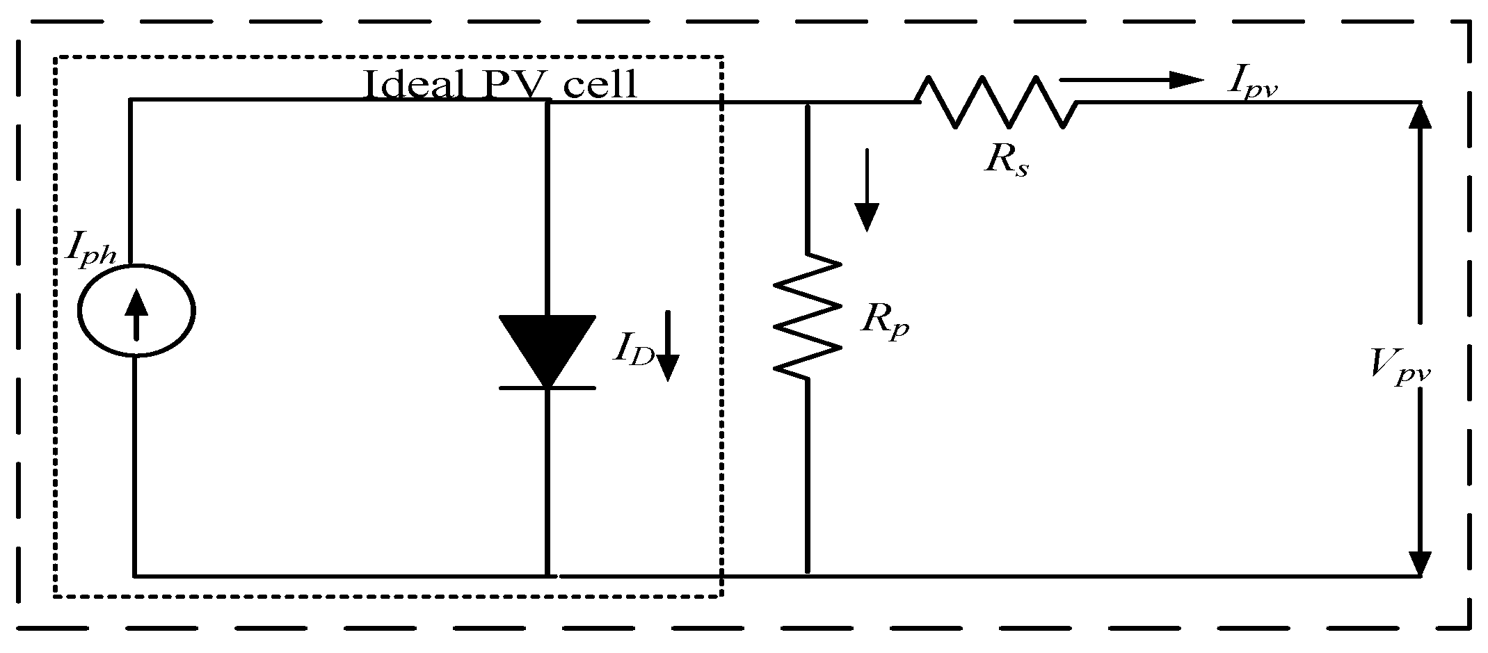
11]. When it is exposed to light, it releases electrons across the closed electric circuit. The symbolic structure of a PV solar cell is depicted in
Figure 1. When electrons collide with photons, cells attain higher levels of energy and electrons become free to move across the junction to produce current. The photo current
Ipv produced through the PV cell is dependent on solar illumination level [
10,
18].
Applying Kirchhoff’s current law in
Figure 1, PV cell output current (
Ipv) can be expressed as under [
18]:
Generated current through photon (
Iph) is proportional to the solar irradiation,
ID is diode current and
Ish is shunt resistor current. The PV module characteristic equation can be described as:
where, saturation current is
Io, PV module voltage output is
Vpv, series resistance is
Rs, shunt resistance is
Rsh, no. of cells in series is
Cs, no. of cells in parallel is
Cp, electron charge is
q, identity factor of diode is
Z, Boltzmann constant is
K and
T is the cell temperature.
Iph and
Io are expressed in Equations (4) and (5), respectively as under:
where
Iscc is PV module standard test short circuit current at conduction (STC) 25 °C with 1000 W/m
2, short circuit current coefficient temperature is
Ki, reference temperature is
Tr in Kelvin,
G is the solar irradiation,
Gr is reference solar irradiation,
Isc is the current saturated at 25 °C and
Ego is the band gap.
4. Perturbation and Observation (P&O) MPPT
The MPPT method automatically finds the current or voltage at which a PV array should work to extract the maximum output power under given temperature and irradiance conditions [
20]. The P&O algorithm is very common and suitable for practical applications [
19,
21,
22]. This algorithm is based on the system perturbation by the decreasing or increasing duty cycle and the results are seen on PV output panel. The operational voltage of the PV module is perturbed with a small increment and the consequential change in power (∆
P) is observed. If ∆
P is positive, it is considered that operating point is reaching towards the MPP. If the ∆
P is negative, the operating point moves away from the MPP. As a result, the reverse perturbation direction is needed in the next perturbation cycle. The process is repetitive and duty cycle is generated to feed to the DC-DC boost converter. This algorithm is especially suitable during constant or slow-varying atmospheric conditions [
2,
8]. However, FLC helps to reduce the operating voltage response time, consequently minimizing the loss of power inside the PV system [
19]. FLC based MPPT is discussed in the next section.
5. Fuzzy Logic Control (FLC) Based MPPT
Conventional method P&O may give error in results that is, when solar irradiance is increased, the algorithm moves in the direction of high power and it fixes the operating point, which is not maximum power point (MPP) [
22]. The FLC method is applied in this work in pursuit of improving the control performance of MPP through simulation and modelling based fuzzy logic rule [
8]. FLC technique controller response is faster and also improves the system stability while attempting to reach MPP [
8,
19]. The search process of MPP based on FLC is a heuristic rule and results in being adaptive stepwise, sensorless with respect to sunlight, and convergence is quick with a change in temperature [
8,
10,
11,
23].
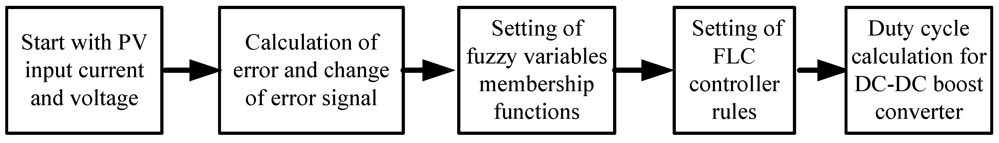
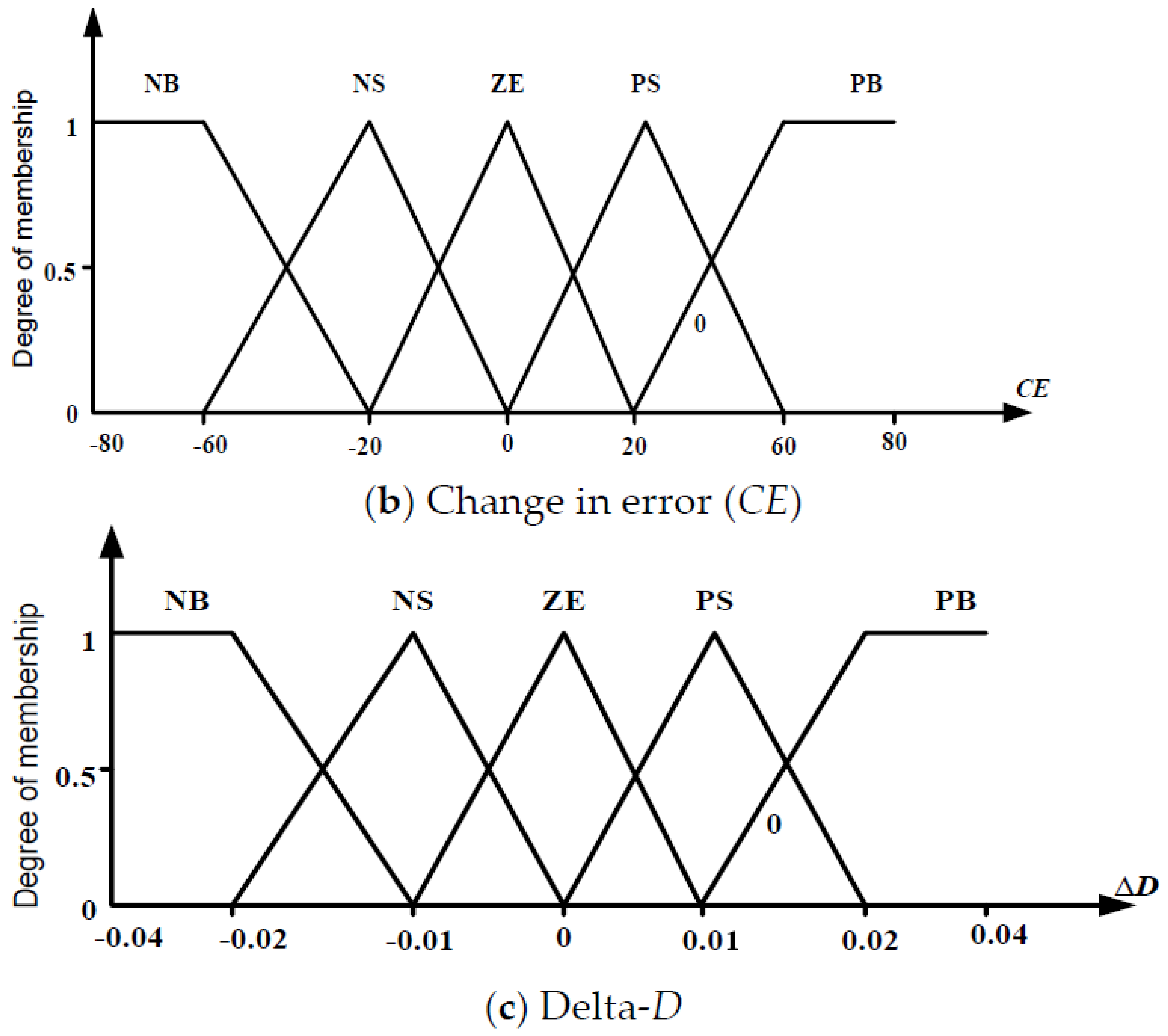
Figure 3 represents the basic concept of FLC based MPPT controller.
The inputs to FLC MPPT are usually an error E and a change in error ΔE. Both are defined in this section. The FLC consists of a functional block, that is, fuzzification, a fuzzy controller algorithm rule and defuzzification. Description of these is presented below:
Fuzzification: The FLC requires input variables for control rules in the form of fuzzy set information with linguistic labels. Actual voltage of the PV array (
V) and current (
I) are measured constantly to calculate power. The control basis is two input variables that is, error
E and change of this error (
CE) at the sampling time
K [
7]. The expressions of variables
E and
CE are as follows:
Here
P(
K) and
I(
K) are the power and current for the PV array, respectively. By using fuzzification of the input variables in
Figure 4a,b and thus obtaining the output of
Figure 4c, they can be compared with pre-defined target values from the fuzzy toolbox. If at the instant
K the input
E(
K) is the operating point located on the left or on the right of the MPP of the
P-
I characteristic, the input error
CE(
K) expresses route of displacement of operating point. The use of the DC-DC converter is to modify the duty ratio delta-
D as the output of the projected controller. Consequently, according to slope
E(
K), by varying the duty ratio control the point is brought back to the point where the slope is zero.
Algorithm Rules (Inference Engine): Inference engine consists of fuzzy rule base and sub-block of fuzzy implication. In this process fuzzifed inputs are fed to the interface engine to apply fuzzy rules. The rule settings of FLC MPPT, different number of subset has been used block view of the fuzzy logic algorithm in Simulink window. In this paper five linguistic variable are used such as negative big (NB), negative small (NS), zero (ZE), positive small (PS) and positive big (PB) at MATLAB fuzzy toolbox. Membership functions of basic five subsets of fuzzy input and output variables are shown in
Figure 4.
Table 1 shows the control rules of fuzzy associative memory, where the matrix entries are fuzzy sets of error (
E), change of error (
CE) and change in duty ratio (∆
D) to the DC-DC boost converter.
In general, fuzzy control uses methods such as Max-Prod, Somme-Prod and Max-Min interface technique [
7,
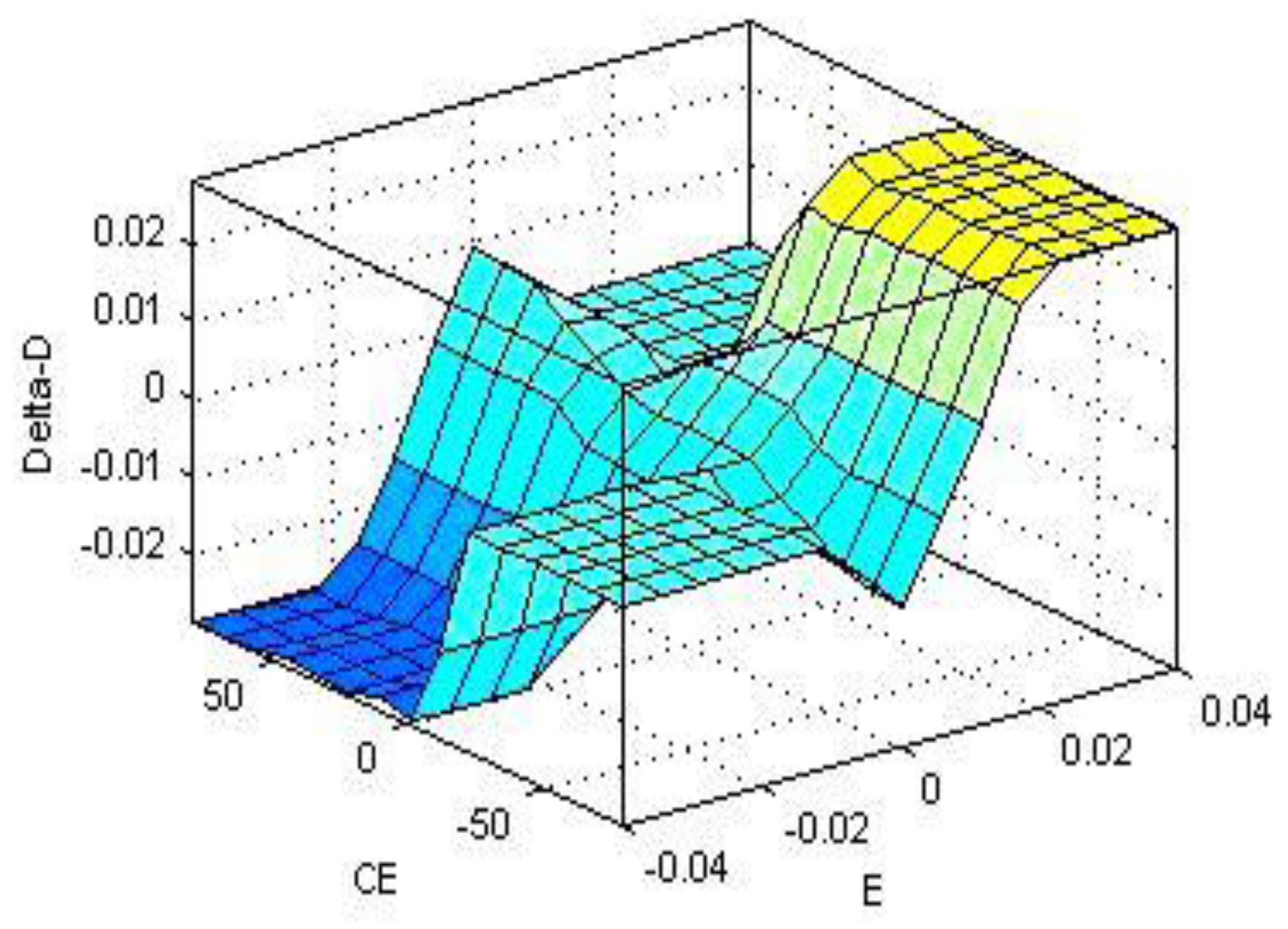
11]. In this paper, the work on the fuzzy technique is performed using the Mamdani inference method, which is an under max-min interface technique of fuzzy combination. The fuzzy control surface for 25 fuzzy control rules on graphical form is presented in
Figure 5.
The output rule viewer of FLC system in MATLAB window is shown in
Figure 6, where the value of error (
E), change in error (
CE) and duty ratio are 0.04, 10.2 and 0.0183, respectively.
Defuzzification: After evaluation of rules, the fuzzy control algorithm calculates the crisp output of the fuzzy controller by performing defuzzification. In this paper, center of gravity method is used for defuzzification [
7,
8]. The center of gravity defuzzification method in a system of rules is formally given by:
where
n is the maximum number of effective rules and
wi is the weighting factor. The output of fuzzy controller ∆
D(
K) is obtained from defuzzification process by Equation (9). Actual duty ratio
D(
K) is obtained as under by making use of gain
SG∆D.
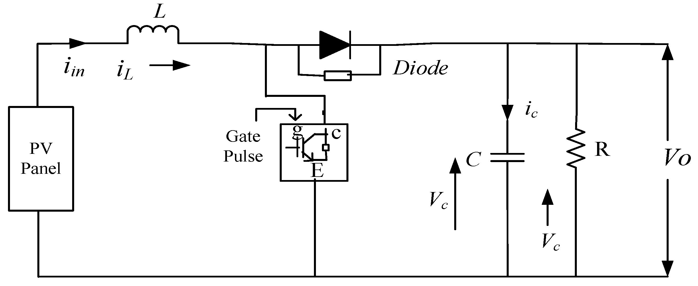
Using the steps mentioned above, the fuzzy controller is implemented for MPPT. Generated output pulse of FLC is used to manage the insulated-gate bipolar transistor (IGBT) switch of DC-DC boost converter.
6. Photovoltaic Based CHB-MLI Configuration and Switching Scheme
CHB-MLI consists of series combination of two or more single phase H-Bridge inverters, where H-bridge is arrangement using switches such as IGBT, metal-oxide-semiconductor field-effect transistor (MOSFET) and so forth [
24,
25,
26,
27,
28,
29]. CHB-MLI has the benefits of “one converter per panel”, such as enhanced operation per PV module, mixing capability of different sources and redundancy of the system. Through the separate DC links voltage control of multilevel inverter is possible independently. As a result, individual MPPT control of each PV panel can be achieved and the harvested energy from PV panel can be maximized. Thus, the modularity and low cost of CHB-MLI makes it a major contender for its proficient, robust and reliable application in solar power electronics [
26]. In the work reported in this paper on single phase 9-level CHB-MLI for PV power generation using MPPT methods, this paper addresses the issues of requirement of individual MPPT to solve mismatch issues of PV panels and in doing so a control scheme with intelligent MPPT (FLC) is also proposed. If each PV panel is not controlled separately, the overall efficiency of PV system will be decreased [
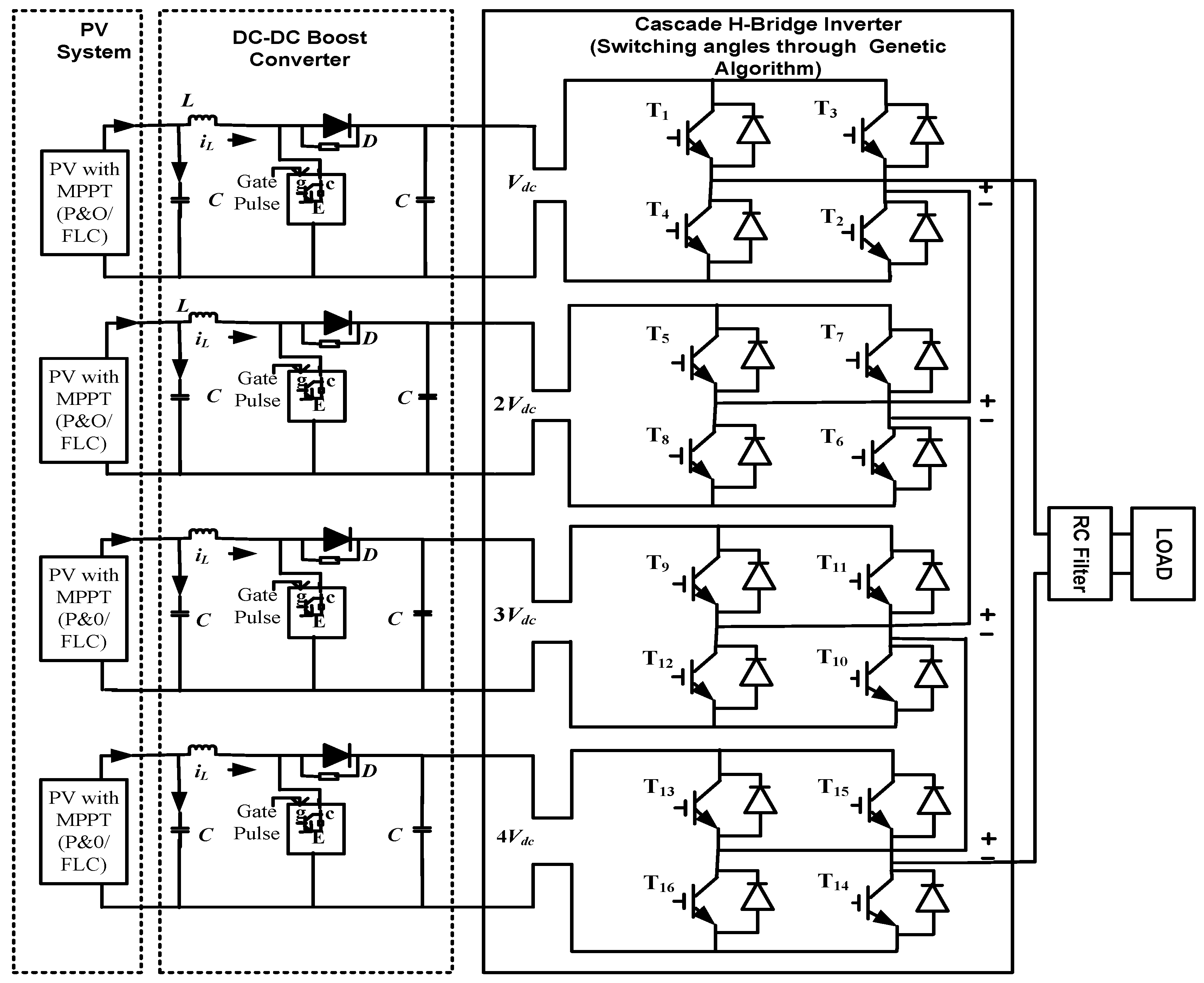
26]. A single phase 9-level CHB-MLI with PV system and DC-DC boost converter configuration is shown in
Figure 7.
The major advantages of the CHB-MLI are that the regulation of the DC buses is easy and it has modularity control [
30,
31,
32].
Table 2 presents the switching schemes of PV system based 9-level single phase CHB-MLI output voltage making use of 16 switches (T
1 to T
16).
Inverter having equal steps was considered in the work of [
15]; however, some investigators may try to provide an optimization of voltage levels of unequal magnitude as shown in
Figure 8 as per reference [
12]. Output waveform pattern with unequal DC source of single phase 9-level CHB-MLI is shown in
Figure 8. The entire output voltage of MLI is specified by
V =
Vdc + 2
Vdc + 3
Vdc + 4
Vdc.
Four switching angles
α1,
α2,
α3 and
α4 are calculated by solving non-linear equating by GA to minimize the THD and resulting output waveform pattern with non-equal DC source of single phase 9-level CHB-MLI is shown in
Figure 8 [
12].
7. Optimization Method for Selected Harmonic Elimination (SHE)
Currently SHE technique is being prominently used to synthesize output voltage of multilevel inverters [
5,
27,
33]. By applying Fourier series analysis, the staircase output voltage of cascaded multilevel inverter with non-equal DC sources can be described as [
15]:
where
Vn is the magnitude of the
nth harmonic. The even order components are equal to zero for such quarter-wave symmetrical signals. Therefore, Equation (11) can be expanded based on the magnitude of each harmonic order as follows. So, the new equation of output voltage becomes as mentioned below:
where
Vdc is the base voltage and
Ki is the ratio of
Vdci to
Vdc. For example,
Vdc1 =
Vdc ×
K1.
Low-order harmonics are generally the targets to reduced using GA technique is concerned. For given voltage levels and switching angles,
F unknown variables should be solved to settle the equation set. Fundamental component forms the Equation (11) as indicated in (13)
where
M is defined as under:
.
Consideration of elimination of triplen harmonics has been described in
Section 1. In this work, targeting the 5th, 7th & 9th harmonics, the four non-linear equations for the solution of the problem are taken as under:
By solving above non-linear equations are targeted to eliminate the 5th, 7th and 9th order harmonics. When conventional technique such as Newton Raphson (NR), resultants methods and so forth are tried to eliminate 5th, 7th and 9th order harmonics, it is known that they have disadvantage of involving high computation time in solving complicated non-linear equation. In this paper, GA approach is used to obtain the optimal value of switching angles of PV based 9-level CHB-MLI considering the total harmonic distortion (THD) an objective function by elimination of 5th, 7th and 9th order harmonics at different value of switching angles. Switching angles are in the range under:
To check the quality of voltage waveform, THD can be defined and calculated as follows
where,
is the voltage of particular harmonics.
8. Genetic Algorithm (GA) Based Optimization Technique for Calculation of Switching Angle
GA is generally used to produce high quality results to complex search problems. The GA based is on relying bio-inspired processes such as crossover, mutation and selection [
34,
35]. It is capable of solving constrained and unconstrained optimization problems based on proper selection of initial population and frequently modifying this individual population for solutions. By selection of individual solutions from each generation, over successive generation multiple individual solutions in this case (switching angle) are selected from the existing inhabitants and the selected solutions are taken in next iteration of the algorithm. The search ends when a final set of solutions for the problem by consecutive generations from a large population is achieved, based on some terminating criteria. Four switching angles are calculated in the present work to achieve the minimum THD keeping the harmonics within the limits as mentioned in Equation (15). In the GA toolbox, graphical user interface allows using GA at MATLAB platform without working at the command line [
5,
34]. The nonlinear equations involved in the present problems are solved with the help of GA toolbox where fitness function, four variables with their range, non-linear constraints and terminating criteria are required to solve the problem [
36]. The detail of these is given below:
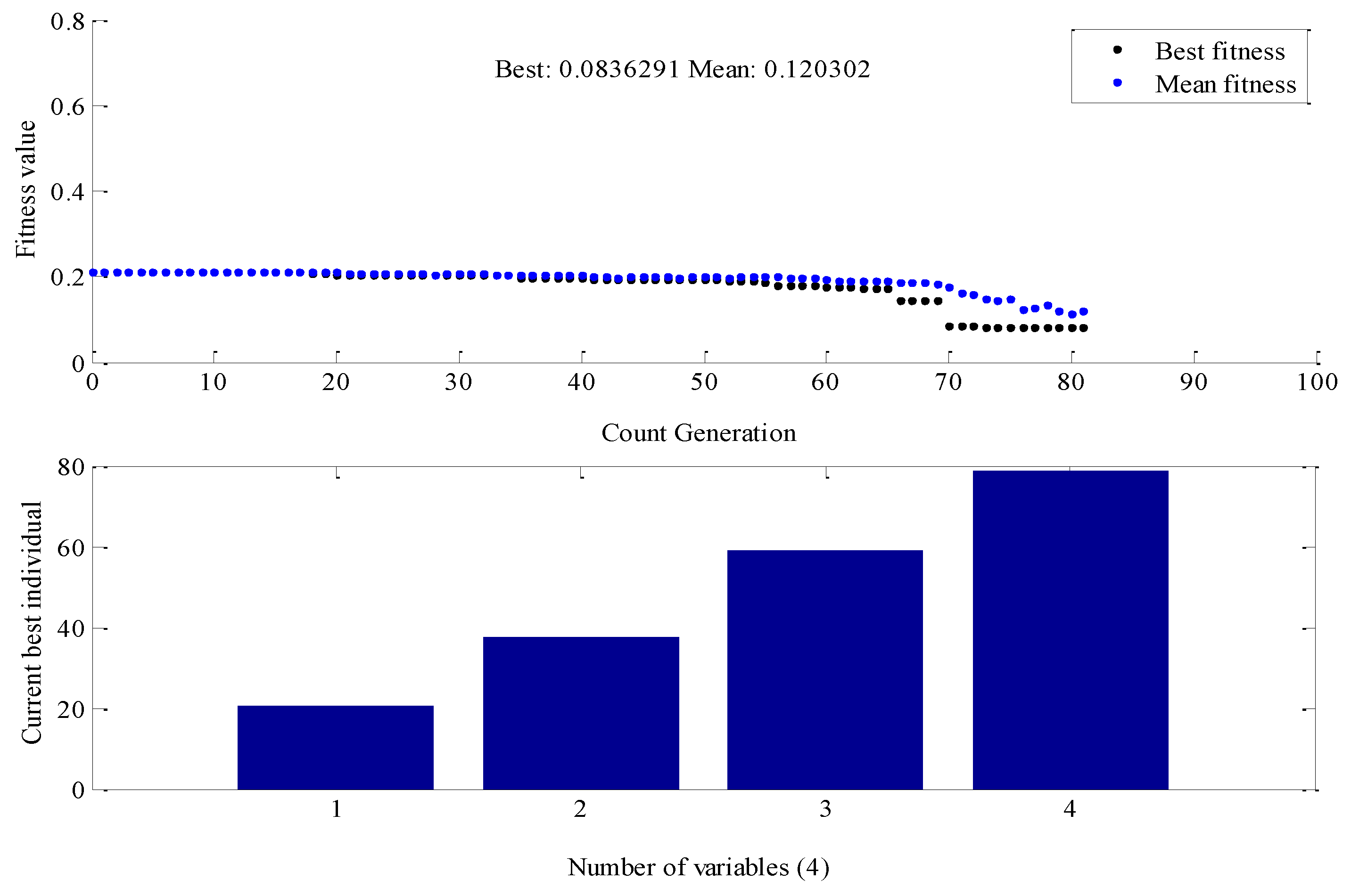
In the work reported in this paper for the design of PV based 9-level CHB-MLI, four switching angles are taken. The best fitness and number of variables obtained using GA toolbox is shown in
Figure 9.
Switching angles of IGBTs are applied through pulse generators. In this GA work, no. of iterations as 100 are selected at GA toolbox. Results of switching angles obtained from GA toolbox are shown in
Table 3.
9. Results and Analysis
Simulation was performed for two cases viz. for PV based boost converter with P&O MPPT incorporated CHB-MLI and for PV based boost converter with FLC MPPT CHB-MLI. Results for both cases are compared for changed temperature and irradiation level. The FLC based algorithm performs fairly well when climate changes. Also, the DC output of each PV panel has less response time and is suitable for input CHB-MLI.
Each solar panel is connected to a separately DC-DC boost converter in order to evaluate the performance of the P&O and FLC MPPTs under changing temperature and irradiation. FLC method can rapidly track the MPP under quickly varying irradiation and temperature with small change in oscillation, while the P&O fails to reach MPP under fast environmental changes. They suffer from high oscillation around MPP and more power loss [
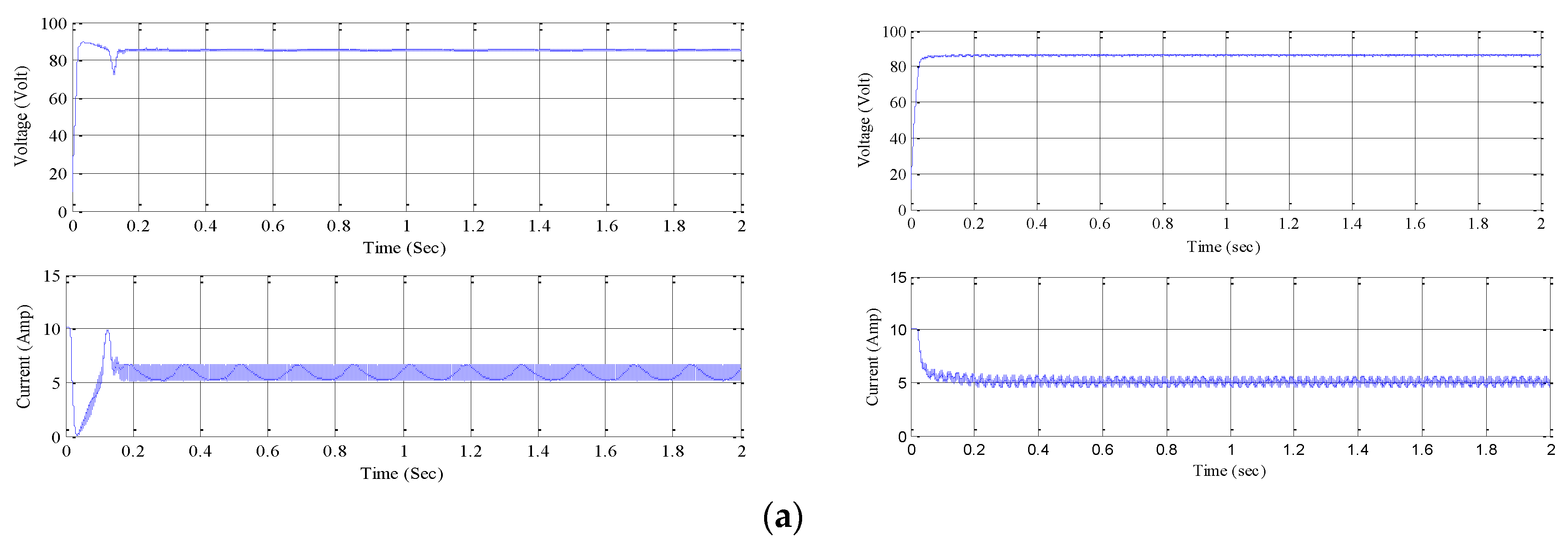
21]. FLC MPPT technique based solar PV system gives much more output voltage as compared to P&O MPPT. Some results of comparison between output voltage and current for each of four panels without boost converter using P&O MPPT and FLC technique are in
Figure 10a–d.
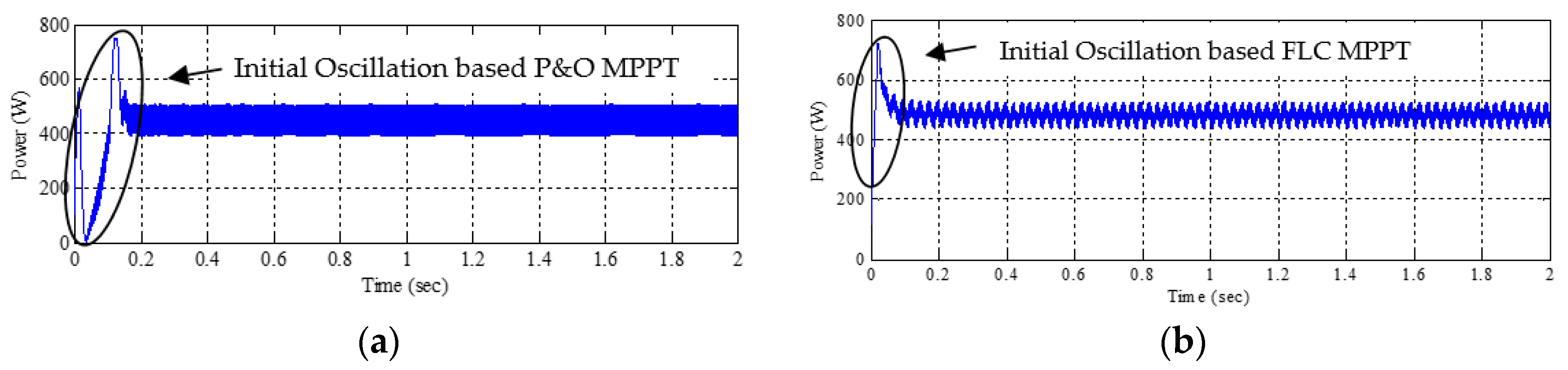
The comparison of output power of panel
1 without boost converter is shown in
Figure 11. The average power of panel
1 without boost converter obtained from both MPPT techniques are approximately equal but FLC based technique produces less oscillation and less power loss as compared to P&O technique.
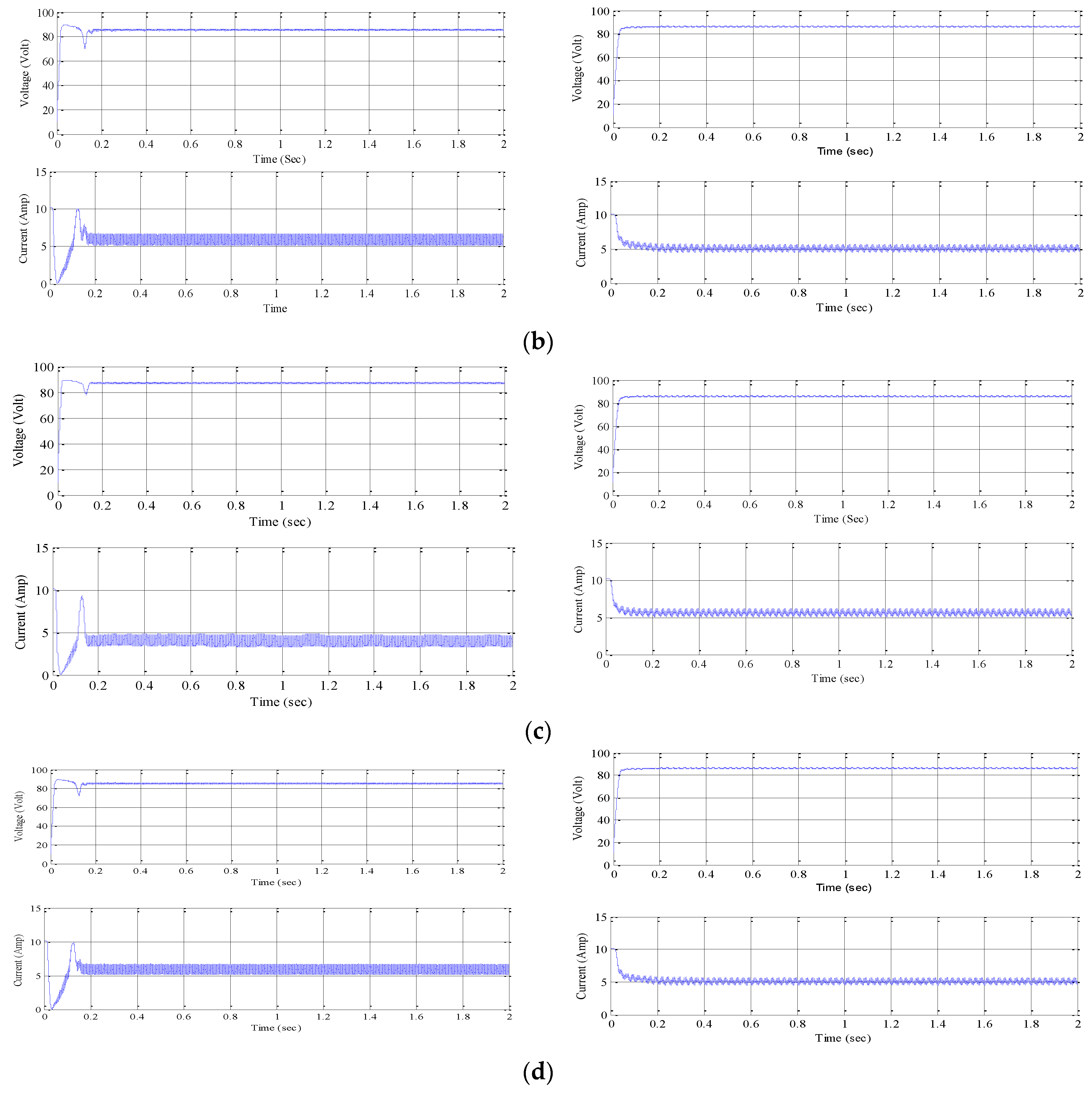
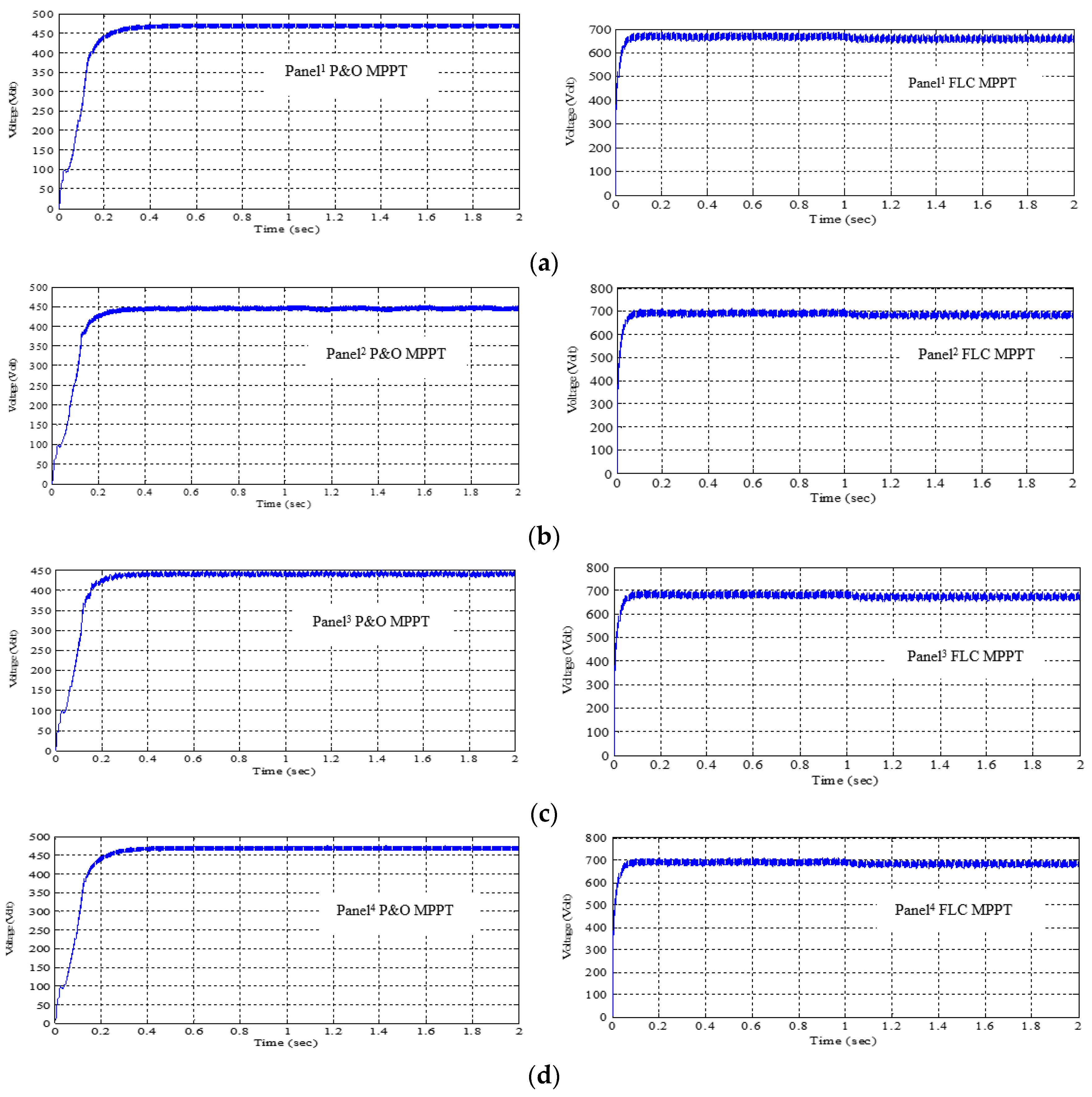
To increase the PV output voltage boost converter is used. Thus, the obtained boosted output voltage from the solar PV arrays is suitable for network voltage rating. The comparison of output voltage for each PV panel using boost converter obtained from P&O and FLC technique is shown in
Figure 12. It can be observed that stability of system is high and output voltage produced is more with less response time (convergence speed) using FLC based MPPT technique as compared to P&O MPPT technique using boost converter.
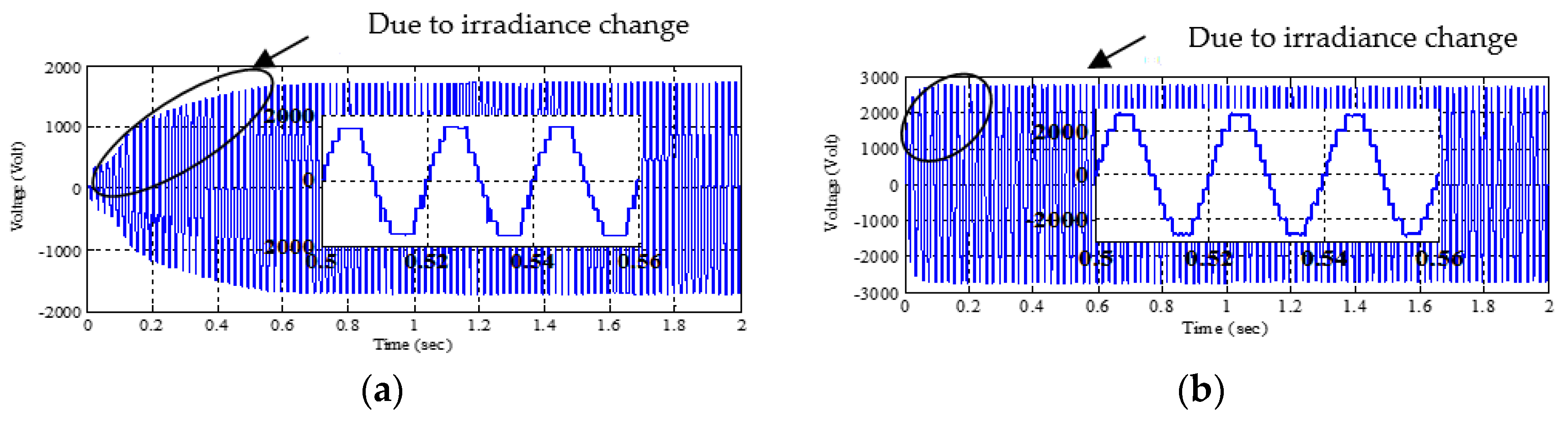
The obtained output voltage of each panel with boost converter is given to 9-level CHB-MLI. Switching angles of IGBTs are applied through pulse generators. In performance optimization using GA to obtain the optimal values of switching angles number of iteration as 100 is selected as it was observed that in doing so with successive generations making use of applied GA method the optimal values were obtained. The comparison of CHB-MLI output voltage without filter, obtained with optimal switching angles fed to inverter IGBTs and using both MPPT methods P&O and FLC based boost converter is shown in
Figure 13. A simple R-L load is connected to the inverter and the output voltage of PV based inverter with boost converter using FLC MPPT technique is more and has less oscillation as compared to P&O MPPT based inverter.
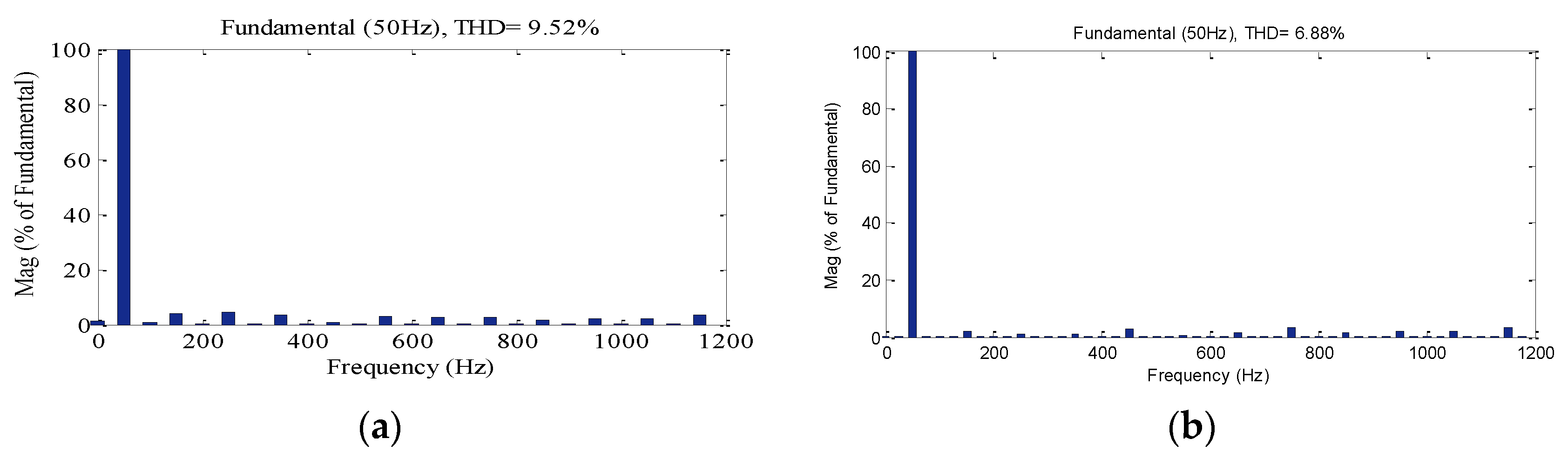
FFT analysis of THD present in the output voltage of CHB-MLI, using both methods, is shown in
Figure 14. The % THD obtained from P&O MPPT technique is 9.52% and from FLC MPPT is 6.88%. Thus, it is observed that FLC MPPT based CHB-MLI technique shows improved performance.
From
Figure 14 it can be observed that lower order harmonics are almost eliminated for both PV based boost converter by P&O MPPT technique as well as PV based boost converter with FLC MPPT technique.
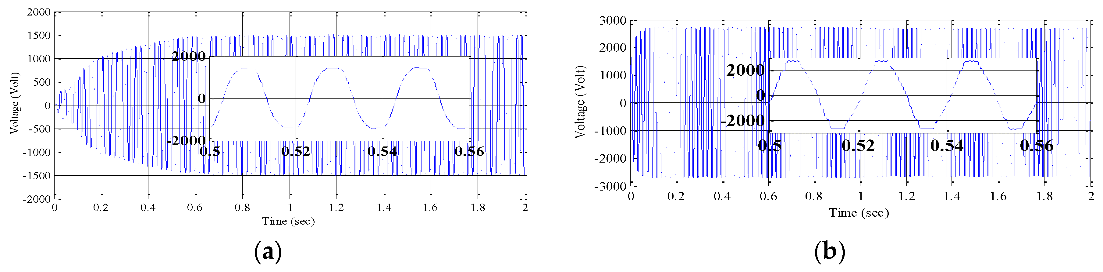
To obtain the sinusoidal output voltage waveform from multilevel inverter use of filter circuit was also attempted in this work. Resistor-capacitor (RC) filter circuit was used to obtain output voltage with less distortion for both MPPT techniques based multilevel inverter.
Figure 15 shows the comparison of output voltage waveform with filter circuit obtained for PV based boost converter using P&O MPPT and using FLC MPPT methods.
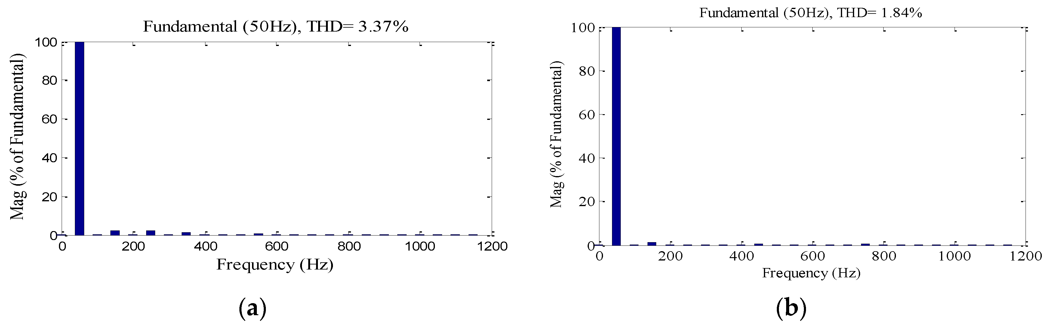
Figure 16a,b shows the comparison of FFT analysis of output voltage THD with filter circuit corresponding to cases of
Figure 15a,b.
Thus, it is observed that for the 9-level PV based CHB-MLI boost converter with FLC MPPT technique the output voltage is more and THD is less, as compared to that obtained using the P&O MPPT technique. A comparison of CHB-MLI performance obtained using P&O and FLC MPPT techniques is shown in
Table 4.
10. Conclusions
This paper presents the work performed on single-phase 9-level PV based CHB-MLI using two MPPT techniques that is, P&O and FLC. Results of comparison obtained using P&O and FLC methods without boost converter, with boost converter, without filter and with filter cases are also presented. By used filter circuit the staircase output voltage waveform of CHB-MLI is improved. Using boost converter with regard to voltage output oscillations, P&O method seems to have just little edge over FLC method; however, FLC method controller response time (convergence speed) for voltage output continued to be lower as compared to P&O method both with & without boost converter. Thus, this work describes that in similar environmental conditions, FLC MPPT based CHB-MLI is capable of increasing the output voltage, reducing power loss, reducing response time of voltage output and reducing THD.
Genetic algorithm is also used in this work targeting selective elimination of harmonics (5th, 7th and 9th) from output voltage to obtain the optimal values of switching angles of single-phase 9-level CHB-MLI corresponding to the minimum of THD. From the obtained results from GA it can be concluded that selective harmonic elimination can be useful for PV based CHB-MLI. The results are obtained using MATLAB software.


