
Highly Sensitive Plasmonic Sensor with Au Bow Tie Nanoantennas on SiO2 Nanopillar Arrays

1
Faculty of Engineering, New York University, Saadiyat Island, Abu Dhabi P.O. Box 129188, United Arab Emirates
2
Department of Mechanical Engineering, New York University, Brooklyn, NY 11201, USA
*
Author to whom correspondence should be addressed.
Chemosensors 2023, 11(2), 121; https://doi.org/10.3390/chemosensors11020121
Submission received: 29 November 2022
/
Revised: 12 January 2023
/
Accepted: 20 January 2023
/
Published: 7 February 2023
(This article belongs to the Special Issue Optical Chemical Sensors and Spectroscopy)
Abstract
:We report on plasmonic sensors based on arrays of metallic bow tie nanoantennas with high sensitivity and an enhanced figure of merit. In the present sensing device, each gold nanoantenna is positioned on the upper surface of a SiO2 nanopillar that is placed on a quartz substrate. The presence of the nanopillar significantly reduces the coupling of the enhanced electromagnetic field generated at the plasmon resonance to the substrate. The simulated results show that the sensitivity of the device to refractive index sensing is 612 nm/RIU, calculated by the resonance wavelength shift per refractive index unit due to the change in the ambient medium index, while the full width at half maximum is calculated at around 10 nm with a figure of merit of 61. The proposed sensor thus has a great potential for sensing and detection applications.
1. Introduction
When light is incident on a metal nanoparticle at the resonant frequency, the conduction electrons are excited, resulting in collective oscillations known as localized surface plasmon resonances (LSPR) [1,2]. The excitation of LSPRs enables the subwavelength localization and enhancement of electromagnetic fields, which are determined by the dielectric properties of the metal and the surrounding medium [3] and by the nanoparticle size and shape [4,5]. Metallic nanoantennas have recently gained much popularity due to their potential to localize and trap electromagnetic fields in nano regimes, attained by the coupling of LSPRs [6]. The recent development in micro-nano fabrication and characterization technologies has led to rapid advancement in improving the performance of the nanoantennas for a variety of applications, such as biological and chemical sensing with enhanced efficiency and sensitivity [7,8,9], wireless communication in nanophotonic chips [10], energy harvesting [11], nanoscale nonlinear optics [12], etc. Single or paired metallic nanoparticles are the most fundamental geometry of a plasmonic antenna. Amongst the other designs, bow tie nanoantennas, made of two gold triangles in a tip-to-tip configuration, provide much stronger electric field localization and enhancement because of the coupling across the gap and the lightning rod effect [13,14,15].
Periodic arrays of metal nanoantennas can generate plasmonic lattice resonances (PLR), arising from the coupling between diffracted waves from the periodic array and the localized surface plasmons of the metal nanoantennas [16,17,18,19,20,21,22]. The coupling generates an enhanced electric field around the nanostructures that can be employed in plasmonic sensors that rely on shifts in their lattice resonant wavelength prompted by an alteration in the refractive indices of the ambient media [23,24,25,26,27]. The performance of a sensor based on such periodic metal arrays is determined by the figure of merit (FOM), which is the ratio of the sensitivity, defined as the shift in the wavelength of PLR per refractive index unit (RIU) to the full width at half maximum (FWHM) [28]. There have been several such geometries arranged in a periodic manner, like L-shaped gold nanobars [29,30], MIM nanograting structures [31], etc., with a higher FOM and sensitivity. In practice, however, any periodic metal arrays require a substrate to be supported. Such substrate-supported nanostructures suffer from the intrinsic drawback that a portion of the electromagnetic field around the structure is transferred to the substrate due to the high refractive index of the latter [32]. This weakens the intensity of the lattice resonance owing to the difference in material properties between the superstrate (air) and the substrate, and thus its FWHM. The detection of resonance shifts of several nanometers in sensitivity studies will thus be hindered, resulting in a reduced FOM of the periodic metal array sensors.
The substrate effect can be overcome by separating the periodic metal arrays from the substrate. One such method is lifting the metal arrays by using dielectric nano-separators such as nanopillars, as has been shown in the literature [33,34]. The refractive index difference between the air and the substrate is reduced because of the lower equivalent index of SiO2 nanopillars, thereby providing a more uniform dielectric environment for the metal arrays. This can increase the efficiency of the PLR formation of the periodic metal arrays as well as the related sensitivity. However, the FWHM of the plasmonic lattice resonance is still relatively wide, and the FOM should be further increased.
Previous studies on overcoming the substrate effect have considered simple metallic nanoparticles in spherical and cylindrical (dielectric pillar) shapes [33,34] or gold caps on photoresists pillars in geometries like plasmonic mushroom arrays [35]. In the present work, we study a geometry combining plasmon-enhanced structures in the form of metallic bow-tie nanoantennas and dielectric pillars to decrease the FWHM of the lattice resonance and improve the FOM. Here, each metallic nanoantenna is placed on top of the dielectric pillar, which in turn is placed on the quartz substrate. The dielectric pillar arrays provide more homogenous surroundings for the nanoantennas, resulting in the formation of the PLRs. This, together with the much-enhanced fields at the gap of metallic nanoantennas, will reduce the FWHM of the lattice resonances. It is shown that the PLRs generated by the present design configuration are more sensitive to the ambient medium, thereby improving the performance of the sensor device, especially in comparison to the previously reported structures [34].
2. Materials and Methods
Figure 1 shows the plasmonic system under study, consisting of an array of Au nanoantennas on SiO2 nanopillar arrays, placed on the surface of a quartz substrate. Each SiO2 nanopillar has a diameter d and height h1. P is the period of the arrays in the x and y directions. A three-dimensional finite difference time domain (3D-FDTD) method implemented in a commercial software from Lumerical Inc. (Canada) is used to conduct the simulations.
Before considering the nanoantennas placed on dielectric pillars, an optimization study of a nanoantenna placed directly on a quartz substrate is conducted to find the geometrical parameters that give the maximum field enhancement at the gap. These parameter optimizations of Au nanoantennas are conducted using FDTD, thereby fixing the geometry of nanoantennas in the subsequent calculations, which is found to be height h2 = 50 nm, the length and width of each nanotriangle in the bow tie = 70 and 150 nm, respectively, and gap distance between the tips of the two nano triangles in the bow tie = 5 nm. Here, the width is the base of the isosceles triangle, and the length is the distance of the perpendicular from the base to the opposite vertex. Each SiO2 nanopillar has a diameter (d) of 200 nm to support the chosen geometry of the nanoantenna on the top of the pillar.
Cartesian coordinates are used to represent the geometry of the device. The x and y axes are in the plane, and the z axis is perpendicular, i.e., parallel to the axis of the cylindrical nanopillars. In all simulations, the mesh size is 2 nm along the three axes. Perfectly matched layers (PML) are kept in the z axis, and periodic Bloch boundary conditions are kept in the x and y axes. Electromagnetic fields in the vicinity of the nanoantennas are simulated presuming plane wave illumination, with wavelengths changing between 500 nm and 1000 nm. The FDTD calculations are performed for the incident electric field with TE (transverse electric) polarization along the axis of the nano antennas. The optical refractive indices (wavelength dependent) of Au and SiO2 are taken from literature [36], and those of the quartz substrate are taken to be constant (ns = 1.46). The refractive index, n, of the ambient media varies from 1.0 to 1.3.
3. Results and Discussions
In a periodic array of metallic nanostructures, different orders of diffraction can be generated if the wavelength of the incident light is comparable to the period of the structures [18]. The projection of the wave vector into the x-y plane is calculated as [18]
where and are components of the wave number along x and y directions, are reciprocal lattice vectors along x and y directions, and and are integers corresponding to diffraction orders. Here, the zeroth-order diffracted wave propagates in the z direction, and the first order propagates horizontally, parallel to the surface. When the incident wavelength is lesser than the period, the zeroth order continues to propagate in the vertical z direction, whereas the first order propagates at an angle to the x-y plane. As the incident wavelength gets longer than the period, the first order vanishes while the zeroth order waves propagate in the z direction. The wavevector component in the z direction is determined as [18]
where is the wave vector magnitude in a medium of refractive index, n.
However, in a periodic array of metallic bow tie nanoantennas, the transmission is influenced by diffraction and also by localized surface plasmon resonance. When the incident wavelength is comparable to the period of the array, the diffraction waves are stronger, and the localized field around the nanoantennas is converted into diffraction waves. This dampens the resonance of the nanostructures, thus increasing the transmission. The threshold wavelength above which this phenomenon happens is the Rayleigh anomaly wavelength [37,38] as follows
where P is the period of the array.
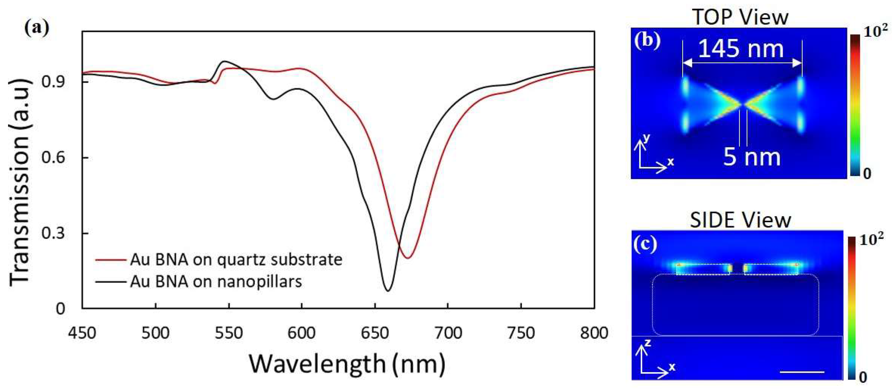
Rayleigh anomaly in the present configuration is observed in the transmission curve for a representative geometry in Figure 2. In Figure 2a, the excitation of the localized plasmons and the diffractive surface waves in periodic Au nanoantenna arrays result in a fan-like shape in transmission. The transmittance varies from the highest, around 550 nm, to the lowest, around 670 nm, in a small range of the spectrum. The highest value of transmittance is generated by the Rayleigh anomaly when a diffraction order appears or disappears [37]. When the incident wavelength rises beyond the period, the first-order wave disappears, but diffraction in the substrate doesn’t die out, and the plasmonic field around the metallic bow tie nanoantennas still dissipates through it. This is the reason for the weakened PLR when the metallic nanoantennas are placed directly on the substrate, as seen in the red curve in Figure 2a. The PLR corresponds to the minimum transmittance, toward the higher wavelength side of the Rayleigh anomaly. The black curve in Figure 2a shows the transmission for Au bow tie nanoantennas on 500 nm high nanopillars, which are placed on the quartz substrate.
The presence of SiO2 nanopillars reduces the line width of the plasmonic lattice resonance, as the former have a similar equivalent refractive index to the air and furnish Au nanoantennas with a homogeneous environment. This reduces the unevenness of the diffraction in the superstrate and in the substrate and facilitates the generation of narrower resonances [39,40]. These resonances will be sensitive to variations in different structural parameters. We now show how the period and height of the SiO2 nanopillars can influence the efficient generation of plasmonic lattice resonances.
3.1. Change in Height of the Nanopillar
Figure 3a shows the transmission spectra of Au bow tie nanoantennas on SiO2 nanopillars for different heights of the nanopillars. When the distance between the quartz substrates and Au nanoantennas is lower, the first-order diffracted waves of the quartz substrate take away the energy from the nanoantennas, leading to a radiative damping of the resonance [33,41]. This weakens the PLR of Au nanoantennas, resulting in a broadening of the resonances.
As the height of the nanopillar is increased, the impact of the quartz substrate on the diffraction is reduced because of the more homogeneous surroundings of the Au nanoantennas. This lowers the transmission at the dip position, allowing more energy to be gathered around the nanoantennas and thus optimizing the PLR. The strength of the diffraction decreases rapidly as the height of the nanopillar is increased, resulting in a rapid decrease in the transmittance in the height range of 350 nm–450 nm of SiO2 nanopillars. The diffraction in the substrate is reduced when the pillar is higher than 500 nm, thereby resulting in a slow reduction of transmission, as is observed as flattening out in Figure 3b. As the height of the pillars is varied, there can also be a periodic change in the reflection from the substrate surface, resulting in constructive and destructive interference with the resonance of the nanostructures and being observed as oscillations in the curve.
3.2. Change in Periodicity of the Arrays
Figure 4a shows the transmission spectra of Au nanoantennas on SiO2 nanopillars for different array periods. When the array period is increased (with other parameters held constant), the PLR wavelength position is red-shifted and the transmission at the PLR wavelength is increased as is observed in Figure 4a. This is because of the red-shifting of the wavelengths of surface diffraction waves, or the Rayleigh anomaly (that propagate in the direction parallel to the substrate surface), which is relative to the period of the arrays and the refractive index of the surrounding medium [37], as is seen in Equation (3). The wavelength shifting of the surface diffraction waves weakens the coupling between the diffracted waves and the localized surface plasmons, resulting in a reduced PLR intensity.
3.3. Sensitivity Studies
Figure 5a shows the transmission spectra of the present sensor in various media environments. Since the wavelength of the diffraction waves is redshifted as per the Rayleigh anomaly [37,39], as the refractive index of the ambient medium increases, the lattice resonant wavelength linearly shifts towards red. Thus, the variation in the refractive index of the ambient medium can be measured by observing the transmission near the resonance wavelength. It can be seen in Figure 5b that as the refractive index of the ambient medium increases from 1.0 to 1.5, the lattice resonance wavelength of the structure with nanopillars predominantly shifts linearly from 653 nm to 959 nm. The sensitivity of the proposed structure, which is the shift of the wavelength of PLR per RIU change, is thereby calculated as 612 nm/RIU.
Moreover, it can be observed from Figure 5a that the FWHM of the PLR is around 10 nm and that it is not susceptible to the refractive index of the ambient medium. The figure of merit (FOM) is calculated as the ratio of sensitivity to FWHM and is thus obtained as 61, which is larger than the previously communicated periodic nanoparticle arrays [42]. In addition, it can be observed from Figure 5b that the presence of SiO2 nanopillar arrays has significantly improved the sensitivity performance of the present device in comparison to the device having nanoantenna arrays directly placed on a quartz substrate.
Previous studies based on the same principle of lifting the nanostructures from the substrate using nanopillars have used different geometries of metallic nanoparticles. Ag nanospheres on silica pillar arrays [43] and Ag/Si/SiO2 nanopillar arrays [34] have demonstrated sensitivities of 460 nm/RIU and 450 nm/RIU, respectively. As noted before, our geometry using metallic bow tie nanoantennas on silica pillar arrays has a sensitivity of 612 nm/RIU with a comparable FOM. This sensitivity is 33% higher than these previously reported values from the literature [34,43].
4. Conclusions
In conclusion, a plasmonic sensor device is developed consisting of Au bow tie nanoantennas on SiO2 nanopillar arrays with a reduced FWHM of the plasmonic lattice resonance of 10 nm (for n = 1.3, P = 550 nm, d = 200 nm, h1 = 500 nm, h2 = 50 nm). The presence of the nanopillars provides a more homogenous surrounding for Au nanoantennas, generating ambient-sensitive PLRs. The effects of different structural parameters, including the height and period of the nanopillar arrays and the ambient medium, on the PLRs generated by the proposed structure are systematically investigated. The calculated refractive index sensitivity of the optimized structure is 612 nm/RIU, which is significantly higher compared to approximately 300 nm/RIU for arrays of Au nanoantennas placed directly on quartz substrates, as well as 450–460 nm/RIU for metallic nanoparticles on silica pillar arrays. The higher sensitivity and narrow FWHM of this device provide potential advantages in improving the development and deployment of plasmonic array sensors in different applications. Our plasmonic system with a high field enhancement at the gap of Au nanoantennas can also be used as a SERS (surface enhanced Raman scattering) sensor [44]. By coupling SERS tags onto the plasmonic sensor chip, SERS sensors can be developed [45]. This sensor configuration, with a more homogenous environment around the nanoantennas, is expected to have an outstanding capability to perform chemical analysis and imaging with the measurement of a wide range of biomolecules.
Author Contributions
Both authors contributed equally to the research and the writing of the manuscript. All authors have read and agreed to the published version of the manuscript.
Funding
This research received no external funding.
Institutional Review Board Statement
Not applicable.
Informed Consent Statement
Not applicable.
Data Availability Statement
The data underlying the results presented in this paper are not publicly available at this time but may be obtained from the authors upon reasonable request.
Conflicts of Interest
The authors declare no conflict of interest.
References
- Rivera, V.; Ferri, F.; Marega, E. Localized Surface Plasmon Resonances: Noble Metal Nanoparticle Interaction with Rare-Earth Ions. In Plasmonics; Young, K.K., Ed.; IntechOpen: Rijeka, Croatia, 2012; Chapter 11. [Google Scholar]
- Mayer, K.M.; Hafner, J.H. Localized Surface Plasmon Resonance Sensors. Chem. Rev. 2011, 111, 3828–3857. [Google Scholar] [CrossRef]
- Hong, R.; Shao, W.; Sun, W.; Deng, C.; Tao, C.; Zhang, D. The influence of dielectric environment on the localized surface plasmon resonance of silver-based composite thin films. Opt. Mater. 2018, 83, 212–219. [Google Scholar] [CrossRef]
- Sandu, T. Shape effects on localized surface plasmon resonances in metallic nanoparticles. J. Nanopart. Res. 2013, 14, 905. [Google Scholar] [CrossRef]
- Ringe, E.; Zhang, J.; Langille, M.; Sohn, K.; Cobley, C.; Au, L.; Xia, Y.; Mirkin, C.; Huang, J.; Marks, L.; et al. Effect of Size, Shape, Composition, and Support Film on Localized Surface Plasmon Resonance Frequency: A Single Particle Approach Applied to Silver Bipyramids and Gold and Silver Nanocubes. MRS Proc. 2010, 1208, 52–57. [Google Scholar] [CrossRef]
- Bharadwaj, P.; Deutsch, B.; Novotny, L. Optical Antennas. Adv. Opt. Photon. 2009, 1, 438–483. [Google Scholar] [CrossRef]
- Biagioni, P.; Huang, J.-S.; Hecht, B. Nanoantennas for visible and infrared radiation. Rep. Prog. Phys. 2012, 75, 024402. [Google Scholar] [CrossRef]
- Venugopalan, P.; Mousavi, N.S.S.; Dabirian, A.; Kumar, S. Ultrasensitive biosensing based on plasmonic nanostructures. In Proceedings of the SPIE Micro + Nano Materials, Devices, and Applications 2019, Melbourne, Australia, 8–12 December 2019. [Google Scholar] [CrossRef]
- Kumawat, N.; Varma, M.; Kumar, S. Phase sensitive diffraction sensor for high sensitivity refractive index measurement. In Proceedings of the SPIE BIOS Optical Diagnostics and Sensing XVIII: Toward Point-of-Care Diagnostics, San Francisco, CA, USA, 27 January–1 February 2018. [Google Scholar] [CrossRef]
- Alù, A.; Engheta, N. Wireless at the Nanoscale: Optical Interconnects using Matched Nanoantennas. Phys. Rev. Lett. 2010, 104, 213902. [Google Scholar] [CrossRef]
- Cao, L.; Fan, P.; Vasudev, A.P.; White, J.S.; Yu, Z.; Cai, W.; Schuller, J.A.; Fan, S.; Brongersma, M.L. Semiconductor Nanowire Optical Antenna Solar Absorbers. Nano Lett. 2010, 10, 439–445. [Google Scholar] [CrossRef] [PubMed]
- Chen, P.-Y.; Argyropoulos, C.; Alù, A. Enhanced nonlinearities using plasmonic nanoantennas. Nanophotonics 2012, 1, 221–233. [Google Scholar] [CrossRef]
- Fromm, D.P.; Sundaramurthy, A.; Schuck, P.J.; Kino, G.; Moerner, W.E. Gap-Dependent Optical Coupling of Single “Bowtie” Nanoantennas Resonant in the Visible. Nano Lett. 2004, 4, 957–961. [Google Scholar] [CrossRef]
- Patel, S.K.; Argyropoulos, C. Plasmonic nanoantennas: Enhancing light-matter interactions at the nanoscale. EPJ Appl. Metamater. 2015, 2, 4. [Google Scholar] [CrossRef]
- Morshed, M.; Khaleque, A.; Hattori, H. Multi-layered bowtie nano-antennas. J. Appl. Phys. 2017, 121, 133106. [Google Scholar] [CrossRef]
- Sadeghi, S.M.; Gutha, R.R.; Wing, W.J. Turning on plasmonic lattice modes in metallic nanoantenna arrays via silicon thin films. Opt. Lett. 2016, 41, 3367–3370. [Google Scholar] [CrossRef]
- Böhm, M.; Uhlig, T.; Derenko, S.; Eng, L.M. Mechanical tuning of plasmon resonances in elastic, two-dimensional gold-nanorod arrays. Opt. Mater. Express 2017, 7, 1882–1897. [Google Scholar] [CrossRef]
- ANikitin, A.G.; Kabashin, A.; Dallaporta, H. Plasmonic resonances in diffractive arrays of gold nanoantennas: Near and far field effects. Opt. Express 2012, 20, 27941–27952. [Google Scholar] [CrossRef]
- Kravets, V.G.; Schedin, F.; Grigorenko, A.N. Extremely Narrow Plasmon Resonances Based on Diffraction Coupling of Localized Plasmons in Arrays of Metallic Nanoparticles. Phys. Rev. Lett. 2008, 101, 087403. [Google Scholar] [CrossRef] [PubMed]
- Humphrey, A.D.; Barnes, W.L. Plasmonic surface lattice resonances in arrays of metallic nanoparticle dimers. J. Opt. 2016, 18. [Google Scholar] [CrossRef]
- Offermans, P.; Schaafsma, M.C.; Rodriguez, S.R.K.; Zhang, Y.; Crego-Calama, M.; Brongersma, S.H.; Rivas, J.G. Universal Scaling of the Figure of Merit of Plasmonic Sensors. ACS Nano 2011, 5, 5151–5157. [Google Scholar] [CrossRef]
- Venugopalan, P.; Kumar, S. Plasmonic properties of gold nanostructures on Hf-doped ZnO film and its application for refractive index sensing with a high figure of merit. Opt. Mater. Express 2022, 12, 2127. [Google Scholar] [CrossRef]
- Su, W.; Ding, Y.; Luo, Y.; Liu, Y. A high figure of merit refractive index sensor based on Fano resonance in all-dielectric metasurface. Results Phys. 2019, 16, 102833. [Google Scholar] [CrossRef]
- Sasi, S.; Francis, S.M.; Jacob, J.; Thomas, V.I. A Tunable Plasmonic Refractive Index Sensor with Ultrabroad Sensing Range for Cancer Detection. Plasmonics 2021, 16, 1705–1717. [Google Scholar] [CrossRef]
- Zhang, Z.; Yang, J.; He, X.; Zhang, J.; Huang, J.; Chen, D.; Han, Y. Plasmonic Refractive Index Sensor with High Figure of Merit Based on Concentric-Rings Resonator. Sensors 2018, 18, 116. [Google Scholar] [CrossRef] [PubMed]
- Butt, M.A.; Khonina, S.N.; Kazanskiy, N.L. Plasmonic refractive index sensor based on metal–insulator-metal waveguides with high sensitivity. J. Mod. Opt. 2019, 66, 1038–1043. [Google Scholar] [CrossRef]
- Butt, M.A.; Kazanskiy, N.L.; Khonina, S.N. Highly Sensitive Refractive Index Sensor Based on Plasmonic Bow Tie Configuration. Photon-Sens. 2020, 10, 223–232. [Google Scholar] [CrossRef]
- Liu, J.; Xu, B.; Zhang, J.; Song, G. Double Plasmon-Induced Transparency in Hybrid Waveguide-Plasmon System and Its Application for Localized Plasmon Resonance Sensing with High Figure of Merit. Plasmonics 2013, 8, 995–1001. [Google Scholar] [CrossRef]
- Khan, A.D. Refractive index sensing with fano resonant L-shaped metasurface. Opt. Mater. 2018, 82, 168–174. [Google Scholar] [CrossRef]
- Li, G.; Hu, H.; Wu, L. Tailoring Fano lineshapes using plasmonic nanobars for highly sensitive sensing and directional emission. Phys. Chem. Chem. Phys. 2019, 21, 252–259. [Google Scholar] [CrossRef]
- Ye, H.-Y.; Huang, X.-Q.; Wen, K.-H.; Xue, J.-C.; Zhou, J.-Y.; Meng, Z.-M. Near-infrared narrow plasmonic resonances for high-performance optical sensing in a sodium-based nanograting. Results Phys. 2022, 38, 105566. [Google Scholar] [CrossRef]
- Martinsson, E.; Otte, M.A.; Shahjamali, M.M.; Sepulveda, B.; Aili, D. Substrate Effect on the Refractive Index Sensitivity of Silver Nanoparticles. J. Phys. Chem. C 2014, 118, 24680–24687. [Google Scholar] [CrossRef]
- Huang, X.; Lou, C.; Zhang, H.; Pribat, D. Plasmonic Lattice Mode Formed by Ag Nanospheres on Silica Pillar Arrays. Plasmonics 2019, 14, 241–245. [Google Scholar] [CrossRef]
- Huang, X.; Zhang, B.; Wang, Y.; Zhu, M.; Shao, G. Reduced resonance line-width and enhanced figure of merit in Ag/Si/SiO2 nanopillar array sensors. Results Phys. 2020, 19, 103612. [Google Scholar] [CrossRef]
- Shen, Y.; Zhou, J.; Liu, T.; Tao, Y.; Jiang, R.; Liu, M.; Xiao, G.; Zhu, J.; Zhou, Z.-K.; Wang, X.; et al. Plasmonic gold mushroom arrays with refractive index sensing figures of merit approaching the theoretical limit. Nat. Commun. 2013, 4, 2381. [Google Scholar] [CrossRef]
- Johnson, P.B.; Christy, R.W. Optical Constants of the Noble Metals. Phys. Rev. B 1972, 6, 4370. [Google Scholar] [CrossRef]
- Maradudin, A.A.; Simonsen, I.; Polanco, J.; Fitzgerald, R.M. Rayleigh and Wood anomalies in the diffraction of light from a perfectly conducting reflection grating. J. Opt. 2016, 18. [Google Scholar] [CrossRef]
- Hessel, A.; Oliner, A.A. A New Theory of Wood’s Anomalies on Optical Gratings. Appl. Opt. 1965, 4, 1275–1297. [Google Scholar] [CrossRef]
- Meier, M.; Wokaun, A.; Liao, P.F. Enhanced fields on rough surfaces: Dipolar interactions among particles of sizes exceeding the Rayleigh limit. J. Opt. Soc. Am. B 1985, 2, 931–949. [Google Scholar] [CrossRef]
- Carron, K.T.; Fluhr, W.; Meier, M.; Wokaun, A.; Lehmann, H.W. Resonances of two-dimensional particle gratings in surface-enhanced Raman scattering. J. Opt. Soc. Am. B 1986, 3, 430–440. [Google Scholar] [CrossRef]
- Huang, X.; Lou, C.; Zhang, H. Experimentally demonstrating plasmonic lattice mode in periodic Ag nanoparticle arrays on quartz trapezoidal pillars. J. Phys. D Appl. Phys. 2018, 51, 465101. [Google Scholar] [CrossRef]
- Kuznetsov, A.; Evlyukhin, A.; Gonçalves, M.R.; Reinhardt, C.; Koroleva, A.; Arnedillo, M.L.; Kiyan, R.; Marti, O.; Chichkov, B. Laser Fabrication of Large-Scale Nanoparticle Arrays for Sensing Applications. ACS Nano 2011, 5, 4843–4849. [Google Scholar] [CrossRef]
- Huang, X.; Lou, C.; Zhang, H.; Yang, H. Effects of different structural parameters and the medium environment on plasmonic lattice resonance formed by Ag nanospheres on SiO2 nanopillar arrays. Chin. Opt. Lett. 2020, 18, 033601. [Google Scholar] [CrossRef]
- Hatab, N.A.; Hsueh, C.-H.; Gaddis, A.L.; Retterer, S.T.; Li, J.-H.; Eres, G.; Zhang, Z.; Gu, B. Free-Standing Optical Gold Bowtie Nanoantenna with Variable Gap Size for Enhanced Raman Spectroscopy. Nano Lett. 2010, 10, 4952–4955. [Google Scholar] [CrossRef] [PubMed]
- Li, M.; Cushing, S.K.; Liang, H.; Suri, S.; Ma, D.; Wu, N. Plasmonic nanorice antenna on triangle nanoarray for surface-enhanced Raman scattering detection of hepatitis B virus DNA. Anal. Chem. 2013, 85, 2072–2078. [Google Scholar] [CrossRef] [PubMed]
Figure 1.
(a) A schematic view of the periodic array of Au bowtie nanoantennas (BNA) on SiO2 nanopillar arrays placed on a quartz substrate; (b) A two-dimensional view of the plasmonic system under investigation (the final optimized geometrical dimensions are shown).
Figure 1.
(a) A schematic view of the periodic array of Au bowtie nanoantennas (BNA) on SiO2 nanopillar arrays placed on a quartz substrate; (b) A two-dimensional view of the plasmonic system under investigation (the final optimized geometrical dimensions are shown).

Figure 2.
(a) The transmission spectra of the plasmonic structures depicted in Figure 1, with P = 550 nm and n = 1. The black curve is for Au bow tie nanoantennas on SiO2 nanopillars, which are placed on the quartz substrate. The red curve is for Au bow tie nanoantennas directly placed on the quartz substrate. Electric field distribution, abs (E/E0) (in a linear scale), of the structure with Au bow tie nanoantennas on nanopillar, which is placed on the quartz substrate (b) top view (c) side view.

Figure 3.
(a) The transmission spectra of Au nanoantennas on SiO2 nanopillars for different heights of the nanopillars, for a geometry depicted in Figure 1. (b) The variation of the transmission dip with a periodic increase in the height of the nanopillars.
Figure 3.
(a) The transmission spectra of Au nanoantennas on SiO2 nanopillars for different heights of the nanopillars, for a geometry depicted in Figure 1. (b) The variation of the transmission dip with a periodic increase in the height of the nanopillars.

Figure 4.
(a) The transmission spectra of Au nanoantennas on SiO2 nanopillar arrays for different periods, for a geometry depicted in Figure 1. (b) PLR wavelength versus array period.
Figure 4.
(a) The transmission spectra of Au nanoantennas on SiO2 nanopillar arrays for different periods, for a geometry depicted in Figure 1. (b) PLR wavelength versus array period.

Figure 5.
(a) The transmission spectra of Au nano antennas on SiO2 nanopillars placed on the quartz substrate in different ambient media (b) Comparison of the sensitivity response for the plasmonic systems with (black dotted line) and without nanopillars (red dotted line).
Figure 5.
(a) The transmission spectra of Au nano antennas on SiO2 nanopillars placed on the quartz substrate in different ambient media (b) Comparison of the sensitivity response for the plasmonic systems with (black dotted line) and without nanopillars (red dotted line).

Disclaimer/Publisher’s Note: The statements, opinions and data contained in all publications are solely those of the individual author(s) and contributor(s) and not of MDPI and/or the editor(s). MDPI and/or the editor(s) disclaim responsibility for any injury to people or property resulting from any ideas, methods, instructions or products referred to in the content. |
© 2023 by the authors. Licensee MDPI, Basel, Switzerland. This article is an open access article distributed under the terms and conditions of the Creative Commons Attribution (CC BY) license (https://creativecommons.org/licenses/by/4.0/).
Share and Cite
MDPI and ACS Style
Venugopalan, P.; Kumar, S. Highly Sensitive Plasmonic Sensor with Au Bow Tie Nanoantennas on SiO2 Nanopillar Arrays. Chemosensors 2023, 11, 121. https://doi.org/10.3390/chemosensors11020121
AMA Style
Venugopalan P, Kumar S. Highly Sensitive Plasmonic Sensor with Au Bow Tie Nanoantennas on SiO2 Nanopillar Arrays. Chemosensors. 2023; 11(2):121. https://doi.org/10.3390/chemosensors11020121
Chicago/Turabian StyleVenugopalan, Priyamvada, and Sunil Kumar. 2023. "Highly Sensitive Plasmonic Sensor with Au Bow Tie Nanoantennas on SiO2 Nanopillar Arrays" Chemosensors 11, no. 2: 121. https://doi.org/10.3390/chemosensors11020121
Note that from the first issue of 2016, this journal uses article numbers instead of page numbers. See further details here.