Article

In-Situ Formation of NiFe-MOF on Nickel Foam as a Self-Supporting Electrode for Flexible Electrochemical Sensing and Energy Conversion

1
College of Geography and Environmental Sciences, Zhejiang Normal University, Jinhua 321004, China
2
College of Chemistry and Materials Science, Zhejiang Normal University, Jinhua 321004, China
*
Authors to whom correspondence should be addressed.
These authors contributed equally to this work.
Chemosensors 2023, 11(4), 242; https://doi.org/10.3390/chemosensors11040242
Submission received: 4 March 2023 / Revised: 29 March 2023 / Accepted: 30 March 2023 / Published: 13 April 2023
(This article belongs to the Special Issue Recent Advances in Electrode Materials for Electrochemical Sensing)

Abstract

:
Ni- and Fe-based metal-organic frameworks (NiFe-MOFs) have abundant valence states and have the potential to be used as bifunctional electrode materials. However, unannealed NiFe-MOFs are still not widely used in electrode materials, including electrochemical sensing, supercapacitors, and overall water splitting. In addition, the direct growth of active material on a conductive carrier has been developed as a binder-free strategy for electrode preparation. This strategy avoids the use of insulating binders and additional electrode treatments, simplifies the preparation process of the NiFe-MOFs, and improves the conductivity and mechanical stability of the electrode. Therefore, in this study, we employed a simple solvothermal method combined with an in situ growth technique to directly grow NiFe-MOF-X (X = 4, 8, 12) nanomaterials of different sizes and morphologies on nickel foam at low reaction temperatures and different reaction times. The NiFe-MOF-8 electrode exhibited high capacitive properties, with an area-specific capacitance of 5964 mF cm−2 at 2 mA cm−2 and excellent durability. On the other hand, NiFe-MOF-12 exhibited strong catalytic activity in electrocatalytic tests performed in a 1 M KOH aqueous solution, demonstrating hydrogen evolution reaction (η10 = 150 mV) and oxygen evolution reaction (η50 = 362 mV) activities. The electrochemical sensing tests demonstrated a good response to BPA. Overall, our results suggest that the direct growth of NiFe-MOFs on nickel foam using a simple solvothermal method combined with an in situ growth technique is a promising strategy.

Graphical Abstract

1. Introduction

Environmental protection has led to the increasing global demand for green-efficient energy, and economically sustainable energy sources have become an important object of exploration and research [1,2,3]. Renewable energy sources, such as wind, solar, and tidal energy, are considered to be an effective solution to the fossil fuel crisis and the greenhouse effect [4,5]. However, their intermittent usage makes them require reliable electrochemical devices for practical application. The development of conversion and energy storage devices, such as water electrolysis devices and supercapacitors (SCs), is particularly important [6,7]. Among the many electrochemical energy storage devices, supercapacitors have shown great potential as a new and superior energy storage device due to their extraordinary power density, long-lasting cycle protection, and their ability to act as a bridge between conventional supercapacitors and lithium-ion batteries [8]. However, their low energy density limits the large-scale application of supercapacitors.
Meanwhile, electrochemical water splitting is a simple technology for the production of high-purity hydrogen and is considered one of the most promising production methods for sustainable hydrogen production [9]. Both half-reactions of the processes of OER and HER are limited by the high reaction energy barrier and the large overpotential caused by the slow reaction kinetics of the electrocatalytic process [10]. More efficient catalysts can reduce the reaction onset potential and overpotential, which, in turn, increases the energy conversion efficiency of water electrolysis [11]. Currently, noble metal-based materials are the preferred active catalysts [12,13], but their expensive cost and rarity have prevented their industrial breakthrough. Additionally, electrochemical sensing is a promising monitoring method due to its fast response, high sensitivity, and low cost. However, the performance of electrochemical sensors or supercapacitors and electrochemical water splitting is largely determined by the active materials, especially those with high activity and low-cost electrode materials [14,15,16]. Metal-organic frameworks (MOFs) [17], consisting of organic ligands and metal ions, have numerous redox active sites [18]. Among them, Ni-, Co-, and Fe-based MOFs with d-band electrons, which have high corrosion resistance and abundant valence changes, thus have the potential to be a bifunctional electrode material [19]. However, MOFs prepared without further annealing treatment are still not widely used as electrode materials, including electrochemical sensing, SCs, and water electrolysis [20].
In addition, the direct growth of active materials on conductive carriers has been developed as a binder-free strategy in electrode preparation, where the synthesis and loading of active materials and their construction on collectors (conductive carriers) are carried out simultaneously in a single process without involving insulating binders and additional electrode processing [21,22,23]. This not only simplifies the preparation of electrodes for MOFs but also electrode conductivity and mechanical stability are improved. In this study, NiFe-MOF-X (X = 4, 8, and 12) of different sizes and morphologies that were grown on nickel foam were synthesized by a simple solvothermal method at lower reaction temperatures and different reaction times. The self-supported NiFe-MOF-8 samples show high capacitive properties with an area-specific capacitance of 5964 mF cm−2 at 2 mA cm−2 and stable durability. In contrast, NiFe-MOF-12 exhibited strong catalytic activity in electrocatalytic tests performed in a 1 M KOH aqueous solution (HER (η10 = 150 mV) and OER (η50 = 362 mV)).

2. Experimental Section

2.1. Experimental Medicines

Nickel (II) nitrate hexahydrate, iron (III) chloride hexahydrate (FeCl3·H2O), N, N-dimethylacetamide (DMA), potassium hydroxide (KOH) and anhydrous ethanol, terephthalic acid (PTA).

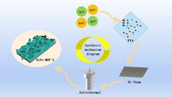
2.2. Synthesis of NiFe-MOF-X

As shown in Figure 1, 124.6 mg of PTA, 109.05 mg of Ni(NO3)2·6H2O, and 101.36 mg of FeCl3·6H2O were dissolved in a mixture of 32 mL of DMA and 2 mL of anhydrous ethanol during the synthesis, which was stirred continuously for 30 min until completely dispersed. The mixture was then transferred to a hydrothermal reactor, and two pieces of nickel foam (2 cm × 1 cm) were placed and reacted at 150 °C for 4, 8, and 12 h. After cooling to room temperature, the powder was collected by centrifugation, washed with water and anhydrous ethanol, and dried overnight at 80 °C under a vacuum. The nickel foam containing the active component was also rinsed several times, then dried and set aside. To investigate the effect of reaction time on the NiFe bimetallic MOF material, the reaction time was adjusted to 4, 8, and 12 h. Other conditions were kept constant, and the products obtained were named NiFe-MOF-X (X = 4, 8, and 12).

2.3. Materials Characterization

The surface microstructure of the material was characterized using a GeminiSEM 300 with an accelerating voltage of 5 kV, and elemental distribution maps was obtained for different reaction times. The chemical bonds and functional groups in the metal-organic framework were analyzed using Fourier transform infrared spectroscopy (FT-IR, Thermo Nicolet, NEXUS 670, Singapore). The crystal structure of the material was obtained by powder XRD (XRD, Bruker, D8-Advance, Billerica, MA, USA) analysis. Raman spectra were obtained by a confocal laser microprobe (Autosorb-mi-MP, Quantachrome, Boynton Beach, FL, USA) system to reveal the molecular vibrations of the electrode materials. XPS (Thermo Fisher Scientific, ESCALAB 250Xi, Waltham, MA, USA) was used to characterize the elemental composition, chemical valence state, and content.

2.4. Electrochemical Measurements

The electrocatalytic performance was tested using a standard three-electrode system in 1.0 M KOH electrolyte with a CHI660E electrochemical workstation (CH Instruments, Inc., Shanghai). During the testing, the synthesized NiFe-MOF-X (X = 4, 8, 12) was used as the working electrode, a platinum sheet as the counter electrode, and a saturated calomel electrode as the reference electrode. Prior to the formal testing, multiple cyclic voltammetry (CV) tests were performed until the curve showed a stable trend. Then, the polarization curve was recorded using linear sweep voltammetry (LSV) with a scan rate of 2 mV s−1. The obtained potential in this work can be calibrated to be consistent with the standard reversible hydrogen electrode (RHE) using the following formula:
ERHE = E(vs SCE) + 0.0591pH + 0.244
The cyclic stability was tested at multiple current densities of 10, 20, 50, 80, and 100 mA cm−2. The chrono-potential (CP) was used to characterize the stability of the electrode material in OER and HER at the same current density (10 mA cm−2).
For the full water splitting test, NiFe-MOF-X was separately used as the anode and cathode to assemble a simple electrochemical water splitting device, and the polarization curve of LSV was obtained with a scan rate of 2 mV s−1. The cyclic stability of the device was evaluated by reacting at a current density of 10 mA cm−2 for 12 h.

3. Results and Discussion

3.1. Conformational Characterization of NiFe-MOF-X

The NiFe-MOF-X was grown directly in situ on nickel foam substrates by a facile and inexpensive solvothermal method, and it exhibited versatile electrochemical properties. The SEM images of the NiFe-MOF-X electrode materials synthesized at different reaction times are shown in Figure 2. Under the same temperature and change in the reaction time, it can be seen that the morphology of NiFe-MOF grown in situ on nickel foam substrates was significantly changed. Specifically, when the reaction time is short (4 h), the reaction may not be complete and sufficient, and NiFe-MOF-4 consists of small particles tightly clustered together with a rougher surface, as shown in Figure 2a,b. After an extended reaction time, the NiFe-MOF-8 morphology changes to a melon-like structure and is not as tightly packed (Figure 2c,d), which is particularly important for faster electrolyte transport and improved charge storage capacity. After extending the reaction time to 12 h, NiFe-MOF-12 can be clearly seen in Figure 2e,f as interlocking smooth nanosheet shapes loaded on a nickel foam substrate and showing ultrathin properties. The large specific surface area of NiFe-MOF-12 enhances the electrochemical catalytic activity of the material by providing more open channels and enabling access to the active sites. Furthermore, by looking at the element mapping images, it can be seen that the four elements, C, O, Fe, and Ni, are evenly distributed across the electrode material (Figure 2g). Since the directly grown NiFe bimetallic MOF has strong adhesion to nickel foam, the above interconnected arrangement and the strong adhesion of the nickel foam substrate can reduce resistance to charge transfer and ion diffusion during the electrochemical reaction [24,25,26], promising good electrochemical properties.

3.2. Structural Characterization of NiFe-MOF-X

Figure 3a shows the X-ray diffraction (XRD) patterns of NiFe-MOF-X (X = 4, 8, and 12). The characteristic diffraction peaks of all three samples are observed to be consistent with those of MIL-53(Fe), indicating that the prepared samples are MIL-53(Fe). Furthermore, it can be concluded that changing the reaction time has a minimal effect on the crystal structure of the material. The Raman spectra in Figure 3b show similar characteristic peaks at 860, 1140, 1440, and 1610 cm−1 for NiFe-MOF at different reaction times, further demonstrating the successful synthesis of NiFe-MOF. Figure 3c,d show the IR spectra, which were used to reveal the chemical bonding in the metal-organic framework. NiFe-MOF-X (X = 4, 8, and 12) also had similar characteristic peaks, demonstrating that the molecular structures of the three samples were essentially identical. The absorption peaks at 1382 cm−1, 1589 cm−1, and 752 cm−1 in the amplified FT-IR spectra at wave numbers from 600 to 2000 cm−1 are attributed to the stretching vibration of the benzene ring C=C, the symmetric and asymmetric vibration of COOH, and the bending vibration of CH on the benzene ring, respectively (Figure 3d) [2]. Meanwhile, a broad and strong peak around 3000 cm−1 is due to the presence of physiosorbed water, and the peak at 1618 cm−1 is also due to the presence of water. All the above results are good evidence that NiFe-MOF was successfully synthesized.
X-ray photoelectron spectroscopy (XPS) reflects the composition and electronic states of materials. The full XPS spectrum in Figure S4 is consistent with the elemental distribution results and also indicates the presence of four elements: C, O, Fe, and Ni. In order to further determine the chemical bonding states of the C, O, Fe, and Ni elements, the NiFe-MOF-X electrode material was analyzed using refined XPS spectra. Figure 4a shows the two compositions of carbon atoms in different functional groups. For the C 1 s spectrum, the peak at 284.7 eV is attributed to C sp2, which enhances the material’s wettability, thereby accelerating the permeation of electrolyte ions [26]. Additionally, the peak at 288.7 eV corresponds to O-C=O, which is favorable for redox reactions and increases the capacitance of the electrode material. In the O 1s XPS spectrum, the peak at 531.7 eV is attributed to lattice oxygen (Figure 4b) [27]. The peaks at 881.5 and 863.9 eV indicate the presence of Ni2+ in the sample. The characteristic peaks at 878.9 and 860.6 eV suggest the existence of Ni3+ (Figure 4c) [28,29]. Similarly, the Fe 2p spectrum can be analyzed (Figure 4d), where the characteristic peaks of Fe 2p3/2 and Fe 2p1/2 appear at 711.6 eV and 724.9 eV, respectively, indicating the presence of Fe3+ and Fe2+ in the electrode material [30]. However, when the reaction time is short, there are no characteristic peaks at 727.8 eV and 714.8 eV for NiFe-MOF-4, indicating that the Fe in this sample exists only in the divalent chemical state.

3.3. Electrochemical Properties of NiFe-MOF-X

The effect of different solvothermal reaction times on the electrocatalytic performance of NiFe-MOF-X was tested in a three-electrode system. Figure 5a shows the OER linear scanning voltammetry curves for the three samples at different reaction times, and it can be seen that the overpotentials of NiFe-MOF-8 and NiFe-MOF-12 are closer to approximately 362 mV at a current density of 50 mA cm−2, with both being lower than NiFe-MOF-4 (480 mV). Notably, an oxidation peak between 1.35 V and 1.5 V appears on the LSV curve, which may be attributed to the redox of the Ni material [31]. Meanwhile, the HER performance of the three samples was explored. The HER polarization curves of NiFe-MOF-4, NiFe-MOF-8, and NiFe-MOF-12 are shown in Figure 5b, from which it can be seen that NiFe-MOF-12 has the best HER catalytic activity, requiring only 150 mV compared to NiFe-MOF-8 and NiFe-MOF-4. The required overpotentials of 192 and 206 mV are much lower, which suggests that increasing the length of the reaction time is beneficial for improving the electrocatalytic performance of the material. Figure 5b,c show the calculated Tafel slopes corresponding to the LSV, from which it can be learned that the Tafel slopes of NiFe-MOF-4, NiFe-MOF-8, and NiFe-MOF-12 are 203, 180, and 134 mV dec−1. The relatively smaller Tafel slope of NiFe-MOF-12 indicates its fast HER kinetics and more efficient electron transport [32]. Similarly, electrochemical impedance tests (Figure 5d) demonstrate that, in general, the smaller semicircles formed in the Nyquist diagram correspond to better electrocatalytic performance and higher Faraday efficiency [33]. From Figure 5d it can be observed that NiFe-MOF-12 exhibits smaller semicircles than NiFe-MOF-8 and NiFe-MOF-4, implying a smaller charge transfer resistance (Rct) for NiFe-MOF-12. in Figure 5e, the tested HER cycling stability of NiFe-MOF-4 and NiFe-MOF-12 at a current density of 10 mA cm−2 shows good stability. Figure 5f shows the HER cycling curves for NiFe-MOF-4 and NiFe-MOF-12 for multiple current steps, and it is found that the samples move from lower current densities to higher current densities and finally back to lower current densities with negligible differences between the overpotential and the initial potential, and NiFe-MOF-12 exhibits a lower overpotential than NiFe-MOF-4 at any current density, further demonstrating the excellent HER cycling stability of NiFe-MOF-12. The superior electrocatalytic activity of NiFe-MOF-12 may be due to its 3D mesh-like nanosheets intertwined and connected, which have a larger specific surface area and an increased number of exposed reactive sites.
Based on the good electrocatalytic OER and HER performance of all samples, the materials were assembled as cathodes and anodes, respectively, in a two-electrode electrolyzer system, where the electrolyte remains an aqueous 1.0 M KOH solution. H2 and O2 are produced on the electrode surface during the reaction. The experimental results show that the NiFe-MOF-12 electrode requires only 1.61 V to achieve a current density of 10 mA cm−2 (Figure 6a), which is less than the 1.64 V of NiFe-MOF-4. Figure 6b shows the stability of the device for electrocatalytic hydrodecomposition at a current density of 10 mA cm−2, where the NiFe-MOF-12 device voltage remains stable after 12 h of continuous hydrodecomposition, as can be seen from the timing potential curve, which was not very significant (Figure 6a). From these results, it can be seen that the electrochemical catalytic decomposition of water using NiFe-MOF-12 as an electrode exhibited good mechanical stability.
In order to explore the performance of NiFe-MOF-X (X = 4, 8, and 12) electrodes as supercapacitor materials, electrochemical evaluations, such as CV, GCD, EIS, and cycling stability tests of the materials, were performed. The CV curves are of NiFe-MOF-4, NiFe-MOF-8, and NiFe-MOF-12 at a scan rate of 5 mV s−1. Instead of a similar standard rectangular shape, the CV curves of the three materials show a Faraday redox peak that can be clearly observed, indicating the typical pseudocapacitance characteristics of the materials. In addition, we can also know that the CV curve area of NiFe-MOF-8 is larger than the other two materials, indicating that NiFe-MOF-8 can store more charge as a supercapacitor anode material. The CV curves of NiFe-MOF-4, NiFe-MOF-8, and NiFe-MOF-12 are shown in Figure S5a–c, where an increase in the scan rate will increase the area of the corresponding CV curve. When the scan rate reaches 50 mV s−1, the redox peak potentials in the CV curves undergo a slight positive or negative shift [34]. The GCD of NiFe-MOF-4, NiFe-MOF-8, and NiFe-MOF-12 as electrode materials was analyzed in depth by GCD tests at different current densities. The GCD curves for all three materials have a voltage window of 0–0.34 V, the curves are all nearly symmetrical and nonlinear in shape (Figure S5d–f), once again demonstrating their pseudocapacitive properties [35]. NiFe-MOF-8 has the longest discharge time, implying a higher specific capacitance, which is in agreement with the conclusions drawn from the CV curves. NiFe-MOF-8 has the largest area-specific capacitance of 5964, 5329, 4458, 3671, 3074, and 2343 mF cm−2. NiFe-MOF-8 has specific capacitances of 5964, 5329, 4458, 3671, 3074, and 2343 mF cm−2 at current densities of 2, 3, 5, 8, 10, and 15 mA cm−2, respectively.
In order to investigate the electrical conductivity of the electrode material in depth, the impedance of the material (EIS) was tested, as shown in Figure 5d. The Nyquist curves for the different samples were all straight lines close to 90°, and all samples had no significant semicircle, indicating a smaller charge transfer resistance. The fact that NiFe-MOF-8 has the largest slope in the low-frequency region indicates the ability of the electrolyte ions to transfer rapidly between the active materials. It is well known that the phase angle of a capacitor is a measure of the capacitive behavior of a supercapacitor and that an ideal capacitor has a phase angle of 90° [36]. The excellent conductivity of NiFe-MOF-8 is further demonstrated by the phase angle versus frequency plots, from which we can conclude that the phase angles of the three electrode materials, NiFe-MOF-4, NiFe-MOF-8, and NiFe-MOF-12, are 80.3°, 81.5° and 81.1°, and NiFe-MOF-8 has a phase angle closer to 90°. This result indicates that the electrochemical behavior of NiFe-MOF-8 is very close to that of an ideal supercapacitor. The melon-like morphology and nanosheet structure of NiFe-MOF-8 and NiFe-MOF-12 effectively avoid agglomeration of nanoparticles and prevent their overgrowth. Thus, by varying the time of the solvothermal reaction and modulating the surface morphology and electronic structure of the NiFe bimetallic MOFs, the conductivity of the materials can be increased to further promote the electron transport capacity. In addition to the electrochemical assessment of the electrode materials described above, cycling durability is also an indicator of supercapacitor performance. Under the current density of 10 mA cm−2, the cycle stability test results after 3000 times of repeated charging and discharging show that NiFe-MOF-8 can still retain 88.54% of the initial capacitance.
In order to confirm the charge storage mechanism, logarithmic calculations based on the NiFe-MOF-8 anode and cathode peak currents in Figure 7a at sweep rates from 5 to 50 mV s−1 yielded b values of 0.45 and 0.41 (b < 0.5) for the anode and cathode peaks, respectively, and the sample was diffusion-control dominated for charge storage; the electrochemical behavior of the material was pure cell behavior.
Another strategy for determining the electrochemical behavior of the reaction process is that the CV curves can be processed and analyzed according to the above equations, as shown in Figure 7b for the NiFe-MOF-8 capacitance and diffusion control contributions at a scan rate of 5 mV s−1, where it is clear that the capacitance control only accounts for a small fraction. By separating the capacitive control component at either voltage from the total current response in the CV curve, the proportion of NiFe-MOF-8 capacitive control at different scan rates can be derived (Figure 7c). The proportion of capacitive control increases gradually with increasing sweep rate, but overall diffusion control dominates. Similarly, the electrochemical behavior of the NiFe-MOF-4 and NiFe-MOF-12 electrodes was quantitatively evaluated according to the method described above. It is not difficult to find that the NiFe-MOF-4 and NiFe-MOF-12 electrodes are also mainly influenced by diffusion control during the charge storage process.
Figure 7d shows a plot between the NiFe-MOF-4, NiFe-MOF-8, and NiFe-MOF-12 peak currents versus the square root of the scan rate. The linear relationship between the two shows that diffusion control determines the electrochemical reaction rate. From the above equation, it is clear that the diffusion coefficient of the reactants is proportional to the slope of the straight line in the graph. This, therefore, indicates that the electrolyte ions have a faster diffusion rate on the NiFe-MOF-8 surface, which facilitates the contact between the electrolyte ions and the electrode material, thus increasing the specific capacity of the electrode material.
The differences in the properties of NiFe-MOF-8 and NiFe-MOF-12 may be attributed to differences in their material structure, surface properties, and catalytic activity. Firstly, there is a difference in the morphology of NiFe-MOF-8 and NiFe-MOF-12, which affects their electrochemical properties and applications. Specifically, NiFe-MOF-8 has a melon-like aggregate structure, while NiFe-MOF-12 has an interlocking smooth nanosheet structure. Due to these structural differences, the two materials exhibit differences in properties such as specific surface area, pore size, and pore structure. Based on these differences, NiFe-MOF-8 has been shown to be an excellent pseudocapacitive supercapacitor electrode material, with high specific surface area and reversible redox reactions. NiFe-MOF-12, on the other hand, is more suitable for use as an electrocatalyst due to the presence of abundant Fe(III) ions in its structure, which exhibit good catalytic activity and selectivity in water-splitting reactions. Additionally, although both NiFe-MOF-8 and NiFe-MOF-12 contain Ni(III) ions, their content and ratio are different, which is also one of the reasons for the differences in their applications. In NiFe-MOF-8, the content of Ni(III) ions is relatively low, and their catalytic activity in electrocatalytic hydrogen production is relatively poor. In NiFe-MOF-12, the content of Ni(III) ions is higher, which may contribute to its improved catalytic activity in electrocatalytic hydrogen production.
The electrochemical behavior of NiFe-MOF-X electrode in a 0.010 mol/L phosphate-buffered solution (PBS, pH = 7.4) with the addition of 50.0 μmol/L BPA was studied using differential pulse voltammetry (DPV), and its electrochemical sensing response to bisphenol A (BPA) was tested as shown in Figure 8. A low peak current was observed in NiFe-MOF-4, indicating slow electron transfer between BPA and the electrode. The oxidation peak of NiFe-MOF-12 appeared at 0.39 V, indicating a significant increase. Compared to other electrodes, Fe-MOF-8 had the highest peak current with its oxidation peak at 0.48 V, indicating the highest detection sensitivity and fastest BPA response.

4. Conclusions

In summary, this study synthesized NiFe-MOF-X (X = 4, 8, and 12) electrode materials directly on nickel foam and varied the reaction time to study the effect of different morphologies and structures on their electrochemical properties. The excellent electrochemical performance exhibited by the NiFe-MOF-8 and NiFe-MOF-12 electrode materials may be attributed to three factors. Firstly, the interwoven melon-like structure and ultrathin 3D-nanosheet structure effectively prevent the agglomeration of nanoparticles and facilitate electrolyte penetration and transport. Secondly, the NiFe bimetallic has multiple valence states, which can provide sufficient reactive sites for redox reactions and increase the material’s specific capacitance, and Fe3+ acts as an efficient promoter for electrochemical OER catalytic reactions. Thirdly, the large, specific surface area of the electrode material can provide more open channels and increase the accessibility of the active sites, thereby enhancing the overall electrochemical performance of the material.

Supplementary Materials

The following supporting information can be downloaded at: https://www.mdpi.com/article/10.3390/chemosensors11040242/s1, Figure S1: EDS mapping images for C, O, Fe and Ni elements of NiFe-MOF-12 nanosheets; Figure S2: Comparison of electrochemical properties of samples with different reaction times: (a) cyclic voltammetry (CV) curves at 5 mV s−1 (b) galvanostatic charge-discharge (GCD) curves at 2 mA cm−2 (c) specific capacitances derived from the discharge profiles at different current densities (d) Nyquist plots of impedance (e) phase angle versus frequency plots (f) cyclic stability test of NiFe-MOF-8; Figure S3: NiFe-MOF-4 and NiFe-MOF-12: (a,d) Logarithmic relationship of peak current and scanning rate (b,e) contribution of the capacitive and diffusion process (c,f) comparison of contribution ratios between capacitive contribution and diffusion-controlled at different scan rates. Figure S4: Measurement of NiFe-MOF-X (X = 4, 8, 12) with different reaction times in a three-electrode system: (a–c) CV curves at different scan rates (d–f) GCD curves at different current densities. Figure S5: XPS spectra of NiFe-MOF-X: survey spectrum; Table S1: The comparison of hydrogen evolution reaction (HER) catalytic activities of Ni/Fe-MOF and other metal catalysts at 10 mA cm−2. References [37,38,39,40,41,42,43,44,45,46,47,48,49,50,51] cited in Supplementary Materials.

Author Contributions

Conceptualization, S.W. and Q.A.; methodology, S.W.; software, Q.A.; validation, Y.J., J.C. and Y.X.; formal analysis, S.W.; investigation, Q.A.; resources, S.W.; data curation, Q.A.; writing—original draft preparation, Q.A. and S.W.; writing—review and editing, Y.J. and J.C.; visualization, Q.A. and S.W.; supervision, Y.J.; project administration, Y.X. and J.C.; funding acquisition, Y.X. and J.C. All authors have read and agreed to the published version of the manuscript.

Funding

This research was funded by [Natural Science Foundation of Zhejiang Province] grant number [LY22E080002].

Institutional Review Board Statement

Not applicable.

Informed Consent Statement

Not applicable.

Data Availability Statement

The data presented in this study are available on request from the corresponding author. The data are not publicly available due to privacy.

Conflicts of Interest

The authors declare no conflict of interest.

References

  1. Li, S.L.; Xu, Q. Metal-organic frameworks as platforms for clean energy. Energy Environ. Sci. 2013, 6, 1656–1683. [Google Scholar] [CrossRef]
  2. Kazemi, S.H.; Karimi, B.; Aghdam, S.A.; Behzadnia, H.; Kiani, M.A. Polyaniline-ionic liquid derived ordered mesoporous carbon nanocomposite: Synthesis and supercapacitive behavior. RSC Adv. 2015, 5, 69032–69041. [Google Scholar] [CrossRef]
  3. Kishore babu, S.; Jayachandran, M.; Maiyalagan, T.; Vijayakumar, T.; Gunasekaran, B. Metal-organic framework (MOF-5) incorporated on NiCo2O4 as electrode material for supercapacitor application. Mater. Lett. 2021, 302, 130338. [Google Scholar] [CrossRef]
  4. Raza, W.; Ali, F.; Raza, N.; Luo, Y.; Kim, K.H.; Yang, J.; Kumar, S.; Mehmood, A.; Kwon, E.E. Recent advancements in supercapacitor technology. Nano Energy 2018, 52, 441–473. [Google Scholar] [CrossRef]
  5. Yan, J.; Wang, Q.; Wei, T.; Fan, Z. Recent advances in design and fabrication of electrochemical supercapacitors with high energy densities. Adv. Energy Mater. 2014, 4, 1300816. [Google Scholar] [CrossRef]
  6. Li, P.Y.; Jiao, Y.; Yao, S.Y.; Wang, L.X.; Chen, G. Dual role of nickel foam in NiCoAl-LDH ensuring high-performance for asymmetric supercapacitors. New J. Chem. 2019, 43, 3139–3145. [Google Scholar] [CrossRef]
  7. Saikia, B.K.; Benoy, S.M.; Bora, M.; Tamuly, J.; Pandey, M.; Bhattacharya, D. A brief review on supercapacitor energy storage devices and utilization of natural carbon resources as their electrode materials. Fuel 2020, 282, 118796. [Google Scholar] [CrossRef]
  8. Huang, Y.; Zeng, Y.; Yu, M.; Liu, P.; Tong, Y.; Cheng, F.; Lu, X. Recent smart methods for achieving high-energy asymmetric supercapacitors. Small Methods 2018, 2, 1700230. [Google Scholar] [CrossRef]
  9. Yu, J.; Dai, Y.; He, Q.; Zhao, D.; Shao, Z.; Ni, M. A mini-review of noble-metal-free electrocatalysts for overall water splitting in non-alkaline electrolytes. Mater. Rep. Energy 2021, 1, 100024. [Google Scholar] [CrossRef]
  10. Zou, X.; Zhang, Y. Noble metal-free hydrogen evolution catalysts for water splitting. Chem. Soc. Rev. 2015, 44, 5148–5180. [Google Scholar] [CrossRef]
  11. Xu, X.M.; Shao, Z.P.; Jiang, S.P. High-Entropy Materials for Water Electrolysis. Energy Technol. 2022, 10, 2200573. [Google Scholar] [CrossRef]
  12. Park, J.; Lee, S.; Kim, H.E.; Cho, A.; Kim, S.; Ye, Y.; Han, J.W.; Lee, H.; Jang, J.H.; Lee, J. Investigation of the support effect in atomically dispersed Pt on WO3-x for utilization of Pt in the hydrogen evolution reaction. Angew. Chem. Int. Ed. Engl. 2019, 58, 16038–16042. [Google Scholar] [CrossRef]
  13. Du, L.; Sun, Y.; You, B. Hybrid water electrolysis: Replacing oxygen evolution reaction for energy-efficient hydrogen production and beyond. Mater. Rep. Energy 2021, 1, 100004. [Google Scholar] [CrossRef]
  14. Urbain, F.; Du, R.; Tang, P.; Smirnov, V.; Andreu, T.; Finger, F.; Divins, N.J.; Llorca, J.; Arbiol, J.; Cabot, A.; et al. Upscaling high activity oxygen evolution catalysts based on CoFe2O4 nanoparticles supported on nickel foam for power-to-gas electrochemical conversion with energy efficiencies above 80%. Appl. Catal. B Environ. 2019, 259, 118055. [Google Scholar] [CrossRef] [Green Version]
  15. Hu, Y.Y.; Yan, C.S.; Chen, D.H.; Lv, C.D.; Jiao, Y.; Chen, G. One-dimensional Co3O4 nanonet with enhanced rate performance for lithium ion batteries: Carbonyl-beta-cyclodextrin inducing and kinetic analysis. Chem. Eng. J. 2017, 321, 31–39. [Google Scholar] [CrossRef]
  16. Kou, T.; Wang, S.; Hauser, J.L.; Chen, M.; Oliver, S.R.J.; Ye, Y.; Guo, J.; Li, Y. Ni foam-supported Fe-doped β-Ni(OH)2 nanosheets show ultralow overpotential for oxygen evolution reaction. ACS Energy Lett. 2019, 4, 622–628. [Google Scholar] [CrossRef]
  17. Xu, Y.C.; Jiao, Y.; Shen, L.G.; Chen, J.R.; Lin, H.J. Ultrathin graphene layer activated dendritic alpha-Fe2O3 for high performance asymmetric supercapacitors. J. Alloy Compd. 2019, 780, 212–219. [Google Scholar] [CrossRef]
  18. Deng, T.; Shi, X.; Zhang, W.; Wang, Z.; Zheng, W. Unlocking the potential of metal organic frameworks for synergized specific and areal capacitances via orientation regulation. Nanotechnology 2021, 32, 075402. [Google Scholar] [CrossRef]
  19. Yuan, C.; Wu, H.B.; Xie, Y.; Lou, X.W. Mixed transition-metal oxides: Design, synthesis, and energy-related applications. Angew. Chem. Int. Ed. Engl. 2014, 53, 1488–1504. [Google Scholar] [CrossRef]
  20. Zhao, C.; Ding, Y.; Zhu, Z.; Han, S.; Zhao, C.; Chen, G. One-pot construction of highly oriented Co-MOF nanoneedle arrays on Co foam for high-performance supercapacitor. Nanotechnology 2021, 32, 395606. [Google Scholar] [CrossRef]
  21. Chen, Q.; Lei, S.; Deng, P.; Ou, X.; Chen, L.; Wang, W.; Xiao, Y.; Cheng, B. Direct growth of nickel terephthalate on Ni foam with large mass-loading for high-performance supercapacitors. J. Mater. Chem. A 2017, 5, 19323–19332. [Google Scholar] [CrossRef]
  22. Wang, J.; Zhong, Q.; Zeng, Y.; Cheng, D.; Xiong, Y.; Bu, Y. Rational construction of triangle-like nickel-cobalt bimetallic metal-organic framework nanosheets arrays as battery-type electrodes for hybrid supercapacitors. J. Colloid Interface Sci. 2019, 555, 42–52. [Google Scholar] [CrossRef] [PubMed]
  23. Nagaraju, G.; Sekhar, S.C.; Ramulu, B.; Hussain, S.K.; Narsimulu, D.; Yu, J.S. Ternary MOF-based redox active sites enabled 3D-on-2D nanoarchitectured battery-type electrodes for high-energy-density supercapatteries. Nanomicro. Lett. 2020, 13, 17. [Google Scholar] [CrossRef] [PubMed]
  24. Wu, J.; Gao, X.; Yu, H.; Ding, T.; Yan, Y.; Yao, B.; Yao, X.; Chen, D.; Liu, M.; Huang, L. A Scalable Free-Standing V2O5/CNT Film Electrode for Supercapacitors with a Wide Operation Voltage (1.6 V) in an Aqueous Electrolyte. Adv. Funct. Mater. 2016, 26, 6114–6120. [Google Scholar] [CrossRef]
  25. Zhang, L.L.; Zhao, X.S. Carbon-based materials as supercapacitor electrodes. Chem. Soc. Rev. 2009, 38, 2520–2531. [Google Scholar] [CrossRef] [PubMed]
  26. Lin, M.X.; Shao, F.Q.; Weng, S.T.; Xiong, S.S.; Liu, S.A.; Jiang, S.Y.; Xu, Y.C.; Jiao, Y.; Chen, J.R. Boosted charge transfer in oxygen vacancy-rich K+ birnessite MnO2 for water oxidation and zinc-ion batteries. Electrochem. Acta 2021, 378, 138147. [Google Scholar] [CrossRef]
  27. Yao, S.Y.; Jiao, Y.; Sun, S.F.; Wang, L.X.; Li, P.Y.; Chen, G. Vertically Co-oriented Mn-Metal-Organic Framework Grown on 2D Cation-Intercalated Manganese Oxide via a Self-sacrificing Template Process for a High-Performance Asymmetric Supercapacitor. ACS Sustain. Chem. Eng. 2018, 42, 4175–4181. [Google Scholar] [CrossRef]
  28. Youn, D.H.; Park, Y.B.; Kim, J.Y.; Magesh, G.; Jang, Y.J.; Lee, J.S. One-pot synthesis of NiFe layered double hydroxide/reduced graphene oxide composite as an efficient electrocatalyst for electrochemical and photoelectrochemical water oxidation. J. Power Sources 2015, 294, 437–443. [Google Scholar] [CrossRef]
  29. Li, J.; Song, J.; Li, X. Rational designing Ni3-xFexS2 nanosheet arrays on Ni foam to enhance supercapacitor performance. Ionics 2020, 26, 3677–3683. [Google Scholar] [CrossRef]
  30. Yamashita, T.; Hayes, P. Analysis of XPS spectra of Fe2+ and Fe3+ ions in oxide materials. Appl. Surf. Sci. 2008, 254, 2441–2449. [Google Scholar] [CrossRef]
  31. Wang, J.; Yang, Z.; Zhang, M.; Gong, Y. Vertically stacked bilayer heterostructure CoFe2O4@Ni3S2 on a 3D nickel foam as a high-performance electrocatalyst for the oxygen evolution reaction. New J. Chem. 2020, 44, 1455–1462. [Google Scholar] [CrossRef]
  32. Du, C.; Shang, M.; Mao, J.; Song, W. Hierarchical MoP/Ni2P heterostructures on nickel foam for efficient water splitting. J. Mater. Chem. A 2017, 5, 15940–15949. [Google Scholar] [CrossRef]
  33. Qu, S.; Huang, J.; Yu, J.; Chen, G.; Hu, W.; Yin, M.; Zhang, R.; Chu, S.; Li, C. Ni3S2 nanosheet flowers decorated with CdS quantum dots as a highly active electrocatalysis electrode for synergistic water splitting. ACS Appl. Mater. Interfaces 2017, 9, 29660–29668. [Google Scholar] [CrossRef] [PubMed]
  34. Kumar, D.R.; Prakasha, K.R.; Prakash, A.S.; Shim, J.J. Direct growth of honeycomb-like NiCo2O4@Ni foam electrode for pouch-type high-performance asymmetric supercapacitor. J. Alloys Compd. 2020, 836, 155370. [Google Scholar] [CrossRef]
  35. Xu, H.; Cao, Y.; Li, Y.; Cao, P.; Liu, D.; Zhang, Y.; Li, Q. High-loading Co-doped NiO nanosheets on carbon-welded carbon nanotube framework enabling rapid charge kinetic for enhanced supercapacitor performance. J. Energy Chem. 2020, 50, 240–247. [Google Scholar] [CrossRef]
  36. Hastak, R.S.; Sivaraman, P.; Potphode, D.D.; Shashidhara, K.; Samui, A.B. All solid supercapacitor based on activated carbon and poly [2, 5-benzimidazole] for high temperature application. Electrochim. Acta 2012, 59, 296–303. [Google Scholar] [CrossRef]
  37. Xuan, C.; Wang, J.; Xia, W.; Peng, Z.; Wu, Z.; Lei, W.; Xia, K.; Xin, H.L.; Wang, D. Porous structured Ni–Fe–P nanocubes derived from a prussian blue analogue as an electrocatalyst for efficient overall water splitting. ACS Appl. Mater. Interfaces 2017, 9, 26134–26142. [Google Scholar] [CrossRef]
  38. Yuan, Q.; Yu, Y.; Gong, Y.; Bi, X. Three-dimensional N-doped carbon nanotube frameworks on Ni foam derived from a metal–organic framework as a bifunctional electrocatalyst for overall water splitting. ACS Appl. Mater. Interfaces 2019, 12, 3592–3602. [Google Scholar] [CrossRef]
  39. Luo, J.; Im, J.H.; Mayer, M.T.; Schreier, M.; Nazeeruddin, M.K.; Park, N.G.; Tilley, S.D.; Fan, H.J.; Grätzel, M. Water photolysis at 12.3% efficiency via perovskite photovoltaics and Earth-abundant catalysts. Science 2014, 345, 1593–1596. [Google Scholar] [CrossRef]
  40. Zhao, X.; Pachfule, P.; Li, S.; Simke, J.R.J.; Schmidt, J.; Thomas, A. Bifunctional Electrocatalysts for Overall Water Splitting from an Iron/Nickel-Based Bimetallic Metal-Organic Framework/Dicyandiamide Composite. Angew. Chem. Int. Ed. Engl. 2018, 57, 8921–8926. [Google Scholar] [CrossRef]
  41. Cheng, N.; Wang, N.; Ren, L.; Casillas-Garcia, G.; Liu, N.; Liu, Y.; Xu, X.; Hao, W.; Dou, S.X.; Du, Y. In-situ grafting of N-doped carbon nanotubes with Ni encapsulation onto MOF-derived hierarchical hybrids for efficient electrocatalytic hydrogen evolution. Carbon 2020, 163, 178–185. [Google Scholar] [CrossRef]
  42. Qiao, H.; Yang, Y.; Dai, X.; Zhao, H.; Yong, J.; Yu, L.; Luan, X.; Cui, M.; Zhang, X.; Huang, X. Amorphous (Fe) Ni-MOF-derived hollow (bi) metal/oxide@ N-graphene polyhedron as effectively bifunctional catalysts in overall alkaline water splitting. Electrochim. Acta 2019, 318, 430–439. [Google Scholar] [CrossRef]
  43. Yu, J.; Lv, C.; Zhao, L.; Zhang, L.; Wang, Z.; Liu, Q. Reverse Microemulsion-Assisted Synthesis of NiCo2S4 Nanoflakes Supported on Nickel Foam for Electrochemical Overall Water Splitting. Adv. Mater. Interfaces 2018, 5, 1701396. [Google Scholar] [CrossRef]
  44. Sun, X.; Shao, Q.; Pi, Y.; Guo, J.; Huang, X. A general approach to synthesise ultrathin NiM (M = Fe, Co, Mn) hydroxide nanosheets as high-performance low-cost electrocatalysts for overall water splitting. J. Mater. Chem. A 2017, 5, 7769–7775. [Google Scholar] [CrossRef]
  45. Kong, F.; Fan, X.; Kong, A.; Zhou, Z.; Zhang, X.; Shan, Y. Covalent phenanthroline framework derived FeS@ Fe3C composite nanoparticles embedding in N-S-codoped carbons as highly efficient trifunctional electrocatalysts. Adv. Funct. Mater. 2018, 28, 1803973. [Google Scholar] [CrossRef]
  46. Dai, X.; Liu, M.; Li, Z.; Jin, A.; Ma, Y.; Huang, X.; Sun, H.; Wang, H.; Zhang, X. Molybdenum polysulfide anchored on porous Zr-metal organic framework to enhance the performance of hydrogen evolution reaction. J. Phys. Chem. C 2016, 120, 12539–12548. [Google Scholar] [CrossRef]
  47. Yan, J.; Ren, C.E.; Maleski, K.; Hatter, C.B.; Anasori, B.; Urbankowski, P.; Sarycheva, A.; Gogotsi, Y. Flexible MXene/graphene films for ultrafast supercapacitors with outstanding volumetric capacitance. Adv. Funct. Mater. 2017, 27, 1701264. [Google Scholar] [CrossRef]
  48. Augustyn, V.; Come, J.; Lowe, M.A.; Kim, J.W.; Taberna, P.L.; Tolbert, S.H.; Hercule, K.M.; Abruna, H.D.; Simon, P.; Dunn, B.; et al. High-rate electrochemical energy storage through Li+ intercalation pseudocapacitance. Nat. Mater. 2013, 12, 518–522. [Google Scholar] [CrossRef] [Green Version]
  49. Owusu, K.A.; Qu, L.; Li, J.; Wang, Z.; Zhao, K.; Yang, C.; Hercule, K.M.; Lin, C.; Shi, C.; Wei, Q.; et al. Low-crystalline iron oxide hydroxide nanoparticle anode for high-performance supercapacitors. Nat. Commun. 2017, 8, 14264. [Google Scholar] [CrossRef] [Green Version]
  50. Askari, M.B.; Salarizadeh, P.; Beheshti-Marnani, A.; Di Bartolomeo, A. NiO-Co3O4-rGO as an efficient electrode material for supercapacitors and direct alcoholic fuel cells. Adv. Mater. Interfaces 2021, 8, 2100149. [Google Scholar] [CrossRef]
  51. Weng, Z.; Su, Y.; Wang, D.W.; Li, F.; Du, J.; Cheng, H.M. Graphene–cellulose paper flexible supercapacitors. Adv. Energy Mater. 2011, 1, 917–922. [Google Scholar] [CrossRef]
Figure 1. Diagrammatic drawing of synthesis process of NiFe-MOF-X (X = 4, 8, 12).
Chemosensors 11 00242 g001
Figure 2. Morphology characterization: SEM images of (a,b) NiFe-MOF-4; (c,d) NiFe-MOF-8; (e,f) NiFe-MOF-12 at various multiples; (g) the elemental mapping pictures of NiFe-MOF-8.
Chemosensors 11 00242 g002
Figure 3. Structure and composition of the samples: (a) XRD patterns; (b) Raman spectrum; (c) FT−IR spectrum; (d) 600~2000 cm−1 enlarged FT−IR spectrum.
Chemosensors 11 00242 g003
Figure 4. XPS spectra of NiFe-MOF-X: High-resolution XPS spectra of (a) C 1s; (b) O 1s; (c) Ni 2p; and (d) Fe 2p.
Chemosensors 11 00242 g004
Figure 5. Comparison of electrocatalytic performance of NiFe-MOF-X (X = 4, 8, 12): (a) OER polarization curves; (b) HER polarization curves; (c) relevant Tafel slopes; (d) Nyquist diagram; (e) chronopotentiometry curves at 10 mA cm−2; and (f) galvanostatic test curves for HER under different current densities for NiFe-MOF-4 and NiFe-MOF-12.
Chemosensors 11 00242 g005
Figure 6. Electrochemical properties of overall water decomposition: (a) LSV curves of initial and after 12 h cycles of NiFe-MOF-4 and NiFe-MOF-12; (b) chronopotentiometry curves for NiFe-MOF-4 and NiFe-MOF-12 at a current density of 10 mA cm −2.
Chemosensors 11 00242 g006
Figure 7. Charge storage mechanism of NiFe-MOF-8: (a) relationship between logarithm peak current and logarithm scan rates; (b) contribution of the capacitive and diffusion process at scan rates of 5 mV s−1 (blue for capacitive contribution); (c) comparison of contribution ratios between capacitive contribution and diffusion-controlled at different scan rates; (d) the relationship between the cathodic and anodic peak currents versus square root of scan rates.
Chemosensors 11 00242 g007
Figure 8. DPVs of NiFe-MOF-X.
Chemosensors 11 00242 g008
Disclaimer/Publisher’s Note: The statements, opinions and data contained in all publications are solely those of the individual author(s) and contributor(s) and not of MDPI and/or the editor(s). MDPI and/or the editor(s) disclaim responsibility for any injury to people or property resulting from any ideas, methods, instructions or products referred to in the content.

