
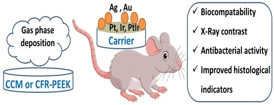
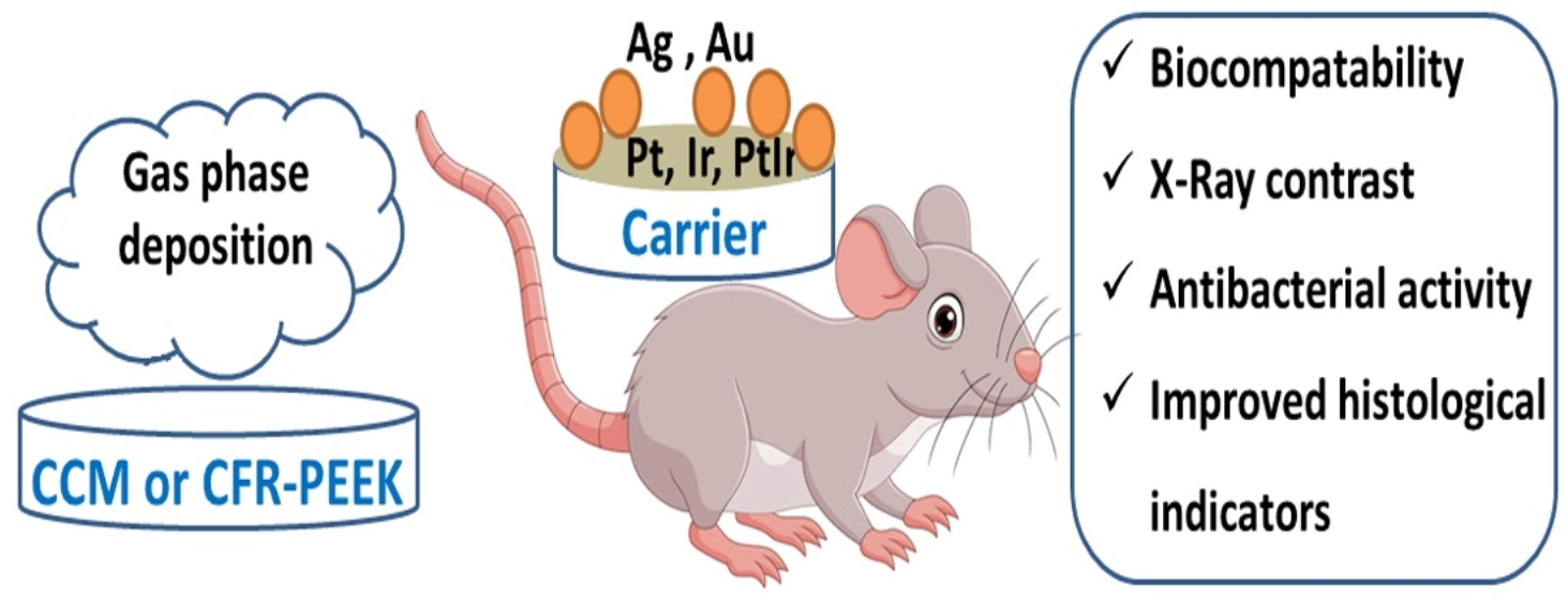
Biological Studies of New Implant Materials Based on Carbon and Polymer Carriers with Film Heterostructures Containing Noble Metals
 ,
,  ,
,  , and
, and 
Abstract
:
1. Introduction
2. Materials and Methods
2.1. Synthesis and Characterization of MOCVD Precursors
2.2. Carrier Materials and Their Characterization
2.3. Deposition of Ir, Pt, PtIr Metal Films and Au, Ag Nanoparticles
2.4. X-ray Diffraction Analysis
2.5. Microscopy
2.6. X-ray Photoelectron Spectroscopy
2.7. Atomic Emission Spectroscopy
2.8. Radiopacity Study
2.9. Biological Studies
2.9.1. Cytotoxicity Studies of Samples
2.9.2. Investigation of Antibacterial Properties of Samples
2.9.3. In Vivo Biocompatibility and Histological Studies
2.9.4. Statistical Analysis
3. Results and Discussion
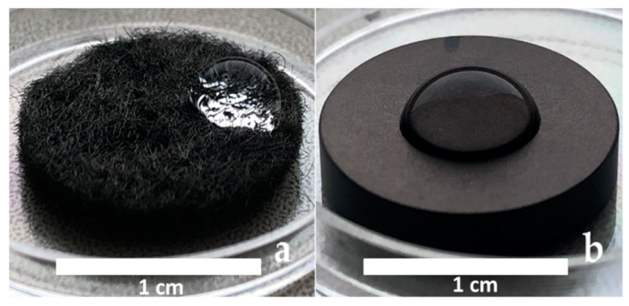
3.1. CCM and CFR-PEEK Carriers
3.2. Deposition and Characterization of Ir, Pt, and PtIr Films
3.2.1. Ir Films
3.2.2. Pt Films
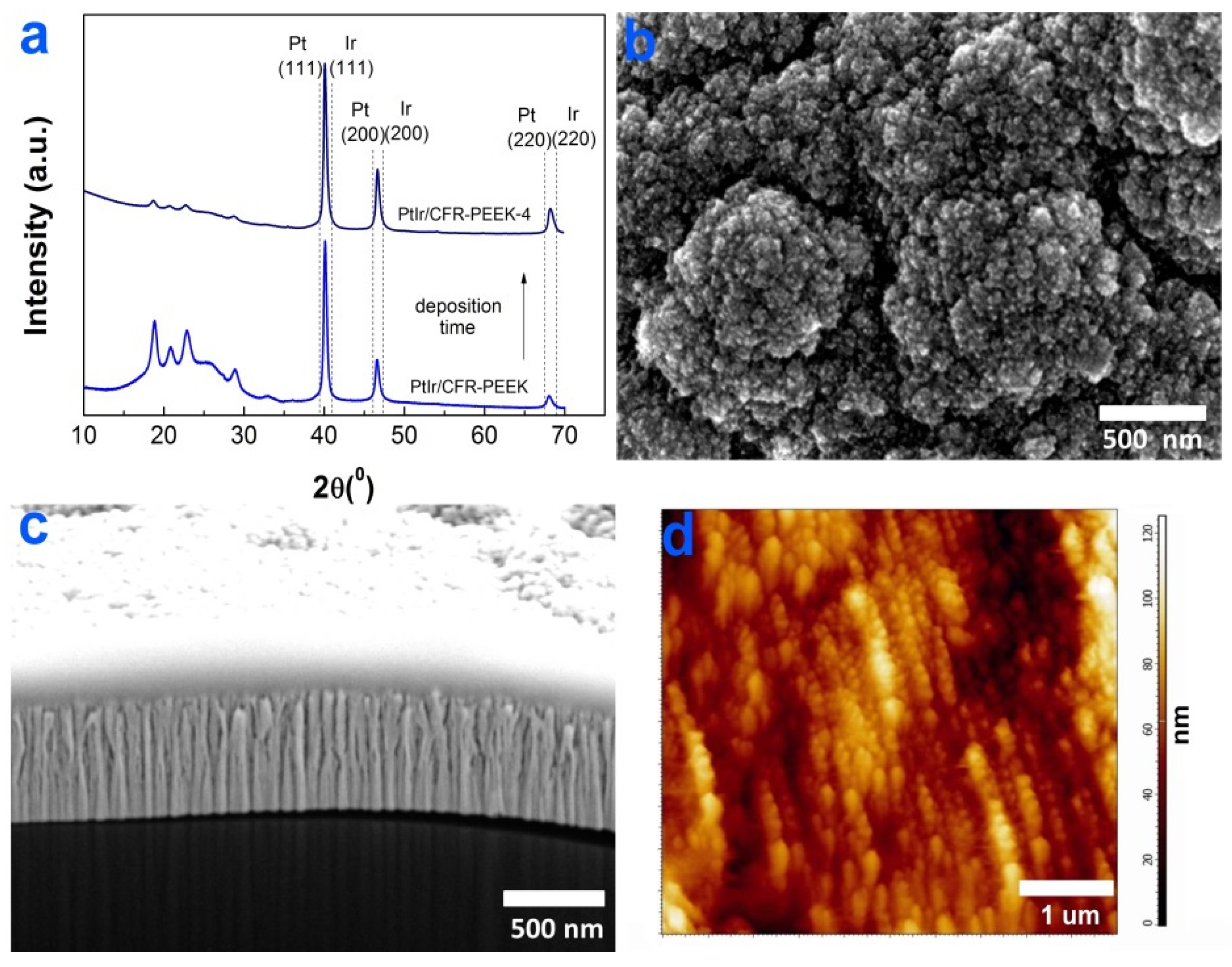
3.2.3. PtIr Films
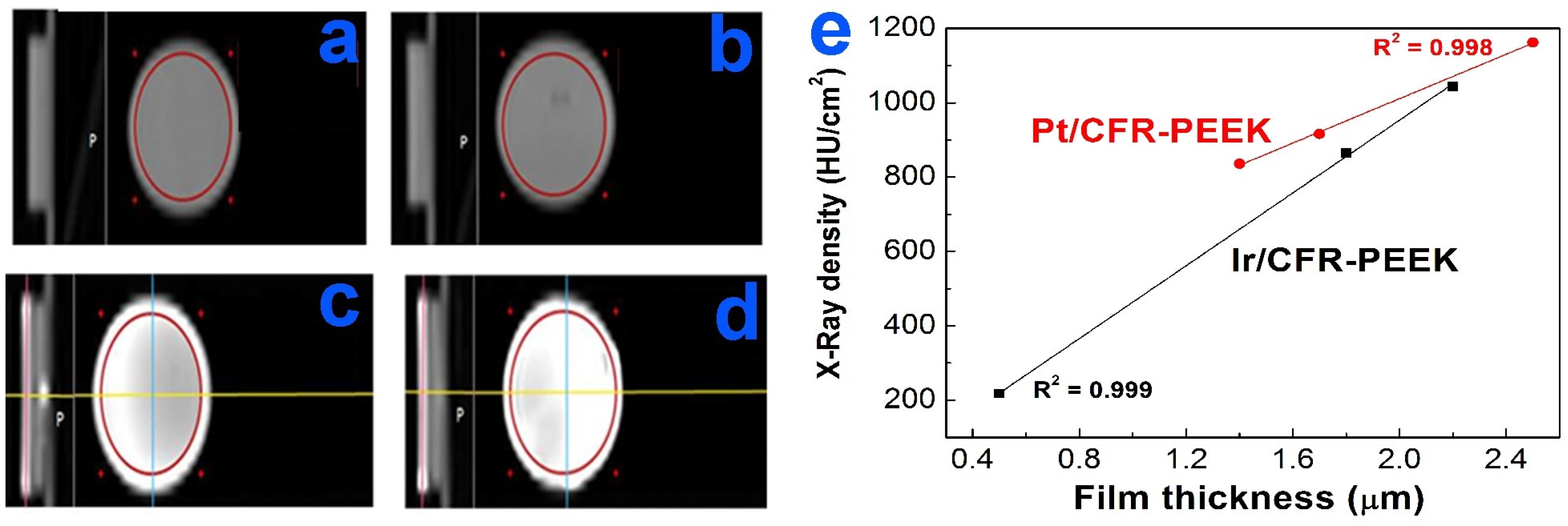
3.3. Radiopacity Study of Ir- and Pt-Coated CFR-PEEK Samples
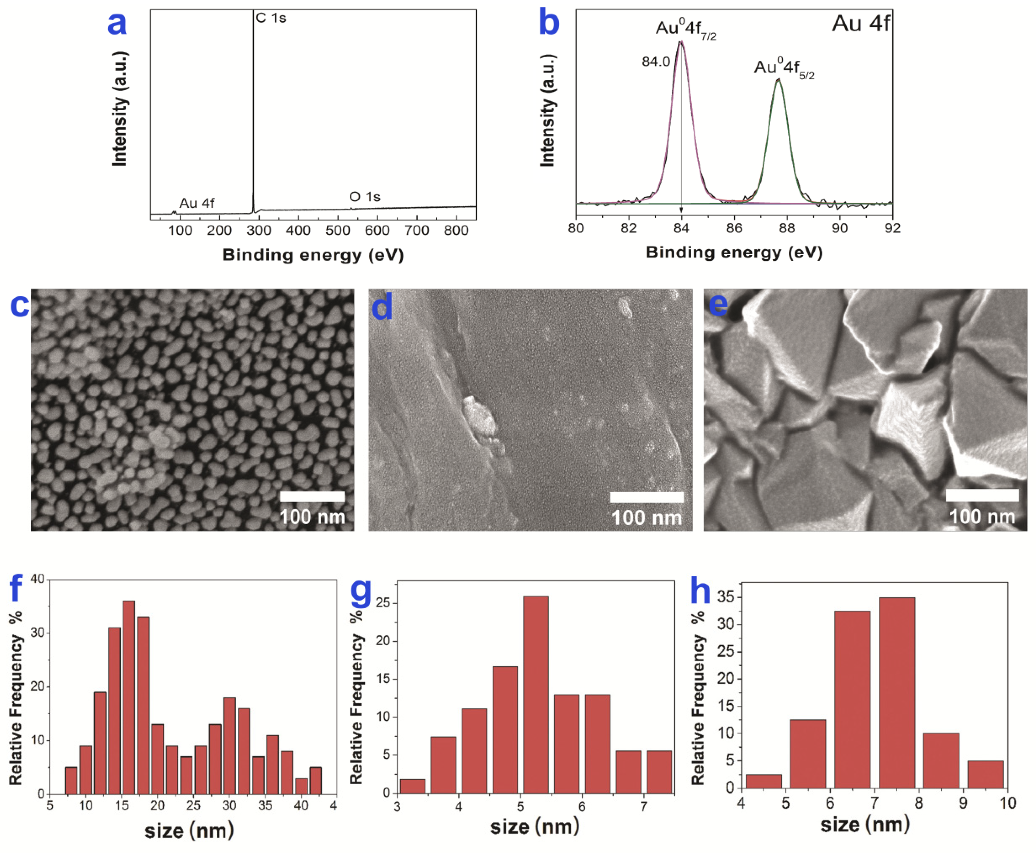
3.4. Ir, Pt and PtIr Coatings Modified with Au Nanoparticles
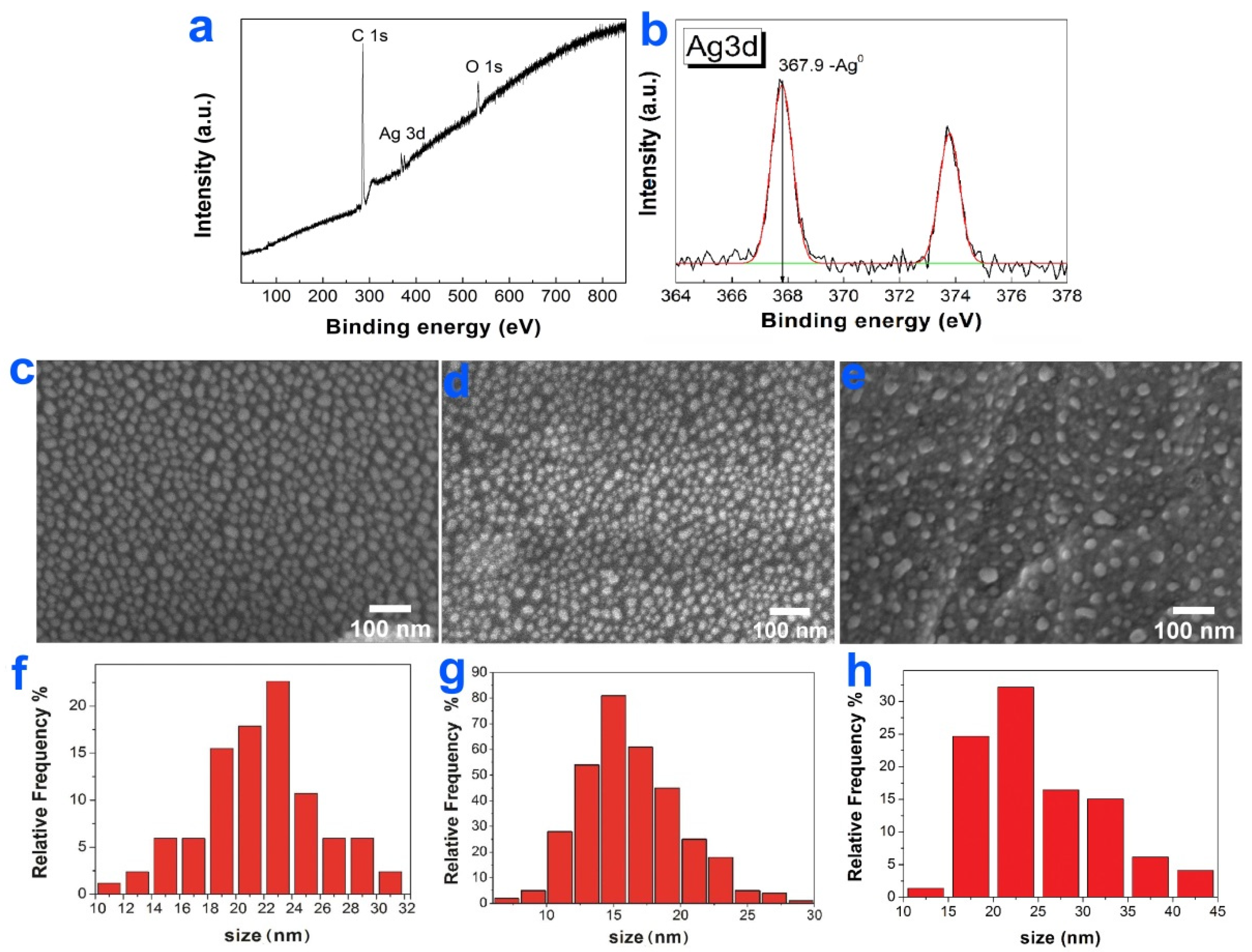
3.5. Ir, Pt, and PtIr Coatings Modified with Ag Nanoparticles
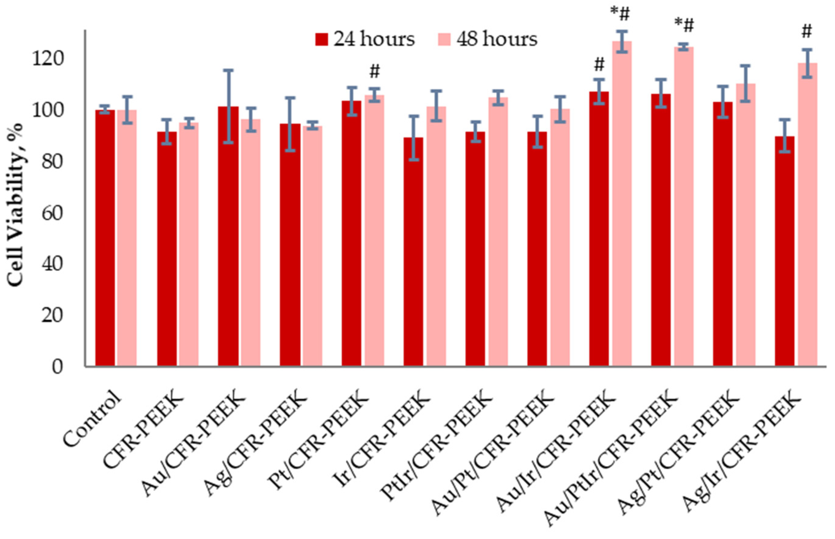
3.6. Cytotoxic Activity
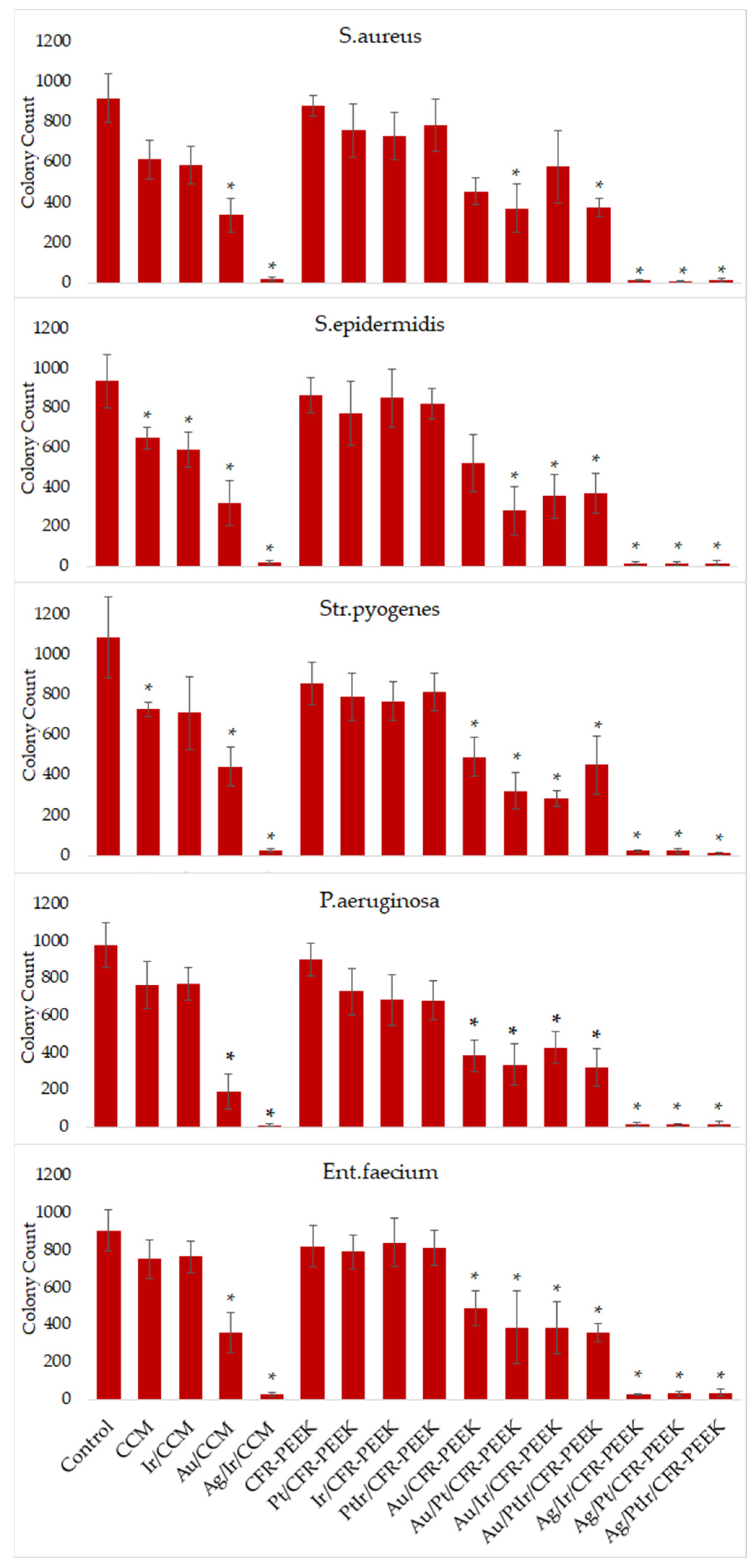
3.7. Antibacterial Activity
- Total growth of bacterial colonies (colony counts ≥ 700, Figure 12a): control, CFR-PEEK, Pt/CFR-PEEK, Ir/CFR-PEEK, PtIr/CFR-PEEK;
- Slightly stunted growth (colony counts = 500–700, Figure 12b): CCM, Ir/CCM;
- Strongly stunted growth (colony counts = 300–500, Figure 12c): Au/CCM, Au/CFR-PEEK, Au/Ir/CFR-PEEK, Au/Pt/CFR-PEEK, Au/PtIr/CFR-PEEK;
- No growth (colony counts = 0–300): Ag/Ir/CCM, Ag/Ir/CFR-PEEK, Ag/Pt/CFR-PEEK, Ag/PtIr/CFR-PEEK.
3.8. Histological Studies
3.8.1. Heterostructures on CCM
3.8.2. Heterostructures on CFR-PEEK
4. Conclusions
Supplementary Materials
Author Contributions
Funding
Institutional Review Board Statement
Informed Consent Statement
Data Availability Statement
Acknowledgments
Conflicts of Interest
References
- Azizi-Lalabadi, M.; Hashemi, H.; Feng, J.; Jafari, S.M. Carbon nanomaterials against pathogens; the antimicrobial activity of carbon nanotubes, graphene/graphene oxide, fullerenes, and their nanocomposites. Adv. Colloid Interface Sci. 2020, 284, 102250. [Google Scholar] [CrossRef]
- Wang, W.; Zhu, Y.; Liao, S.; Li, J. Carbon Nanotubes Reinforced Composites for Biomedical Applications. Biomed. Res. Int. 2014, 2014, 518609. [Google Scholar] [CrossRef]
- Bryan, J.M.; Sumner, D.R.; Hurwitz, D.E.; Tompkins, G.S.; Andriacchi, T.P.; Galante, J.O. Altered load history affects periprosthetic bone loss following cementless total hip arthroplasty. J. Orthop. Res. 1996, 14, 762–768. [Google Scholar] [CrossRef]
- Salgado, A.J.; Coutinho, O.P.; Reis, R.L. Bone tissue engineering: State of the art and future trends. Macromol. Biosci. 2004, 4, 743–765. [Google Scholar] [CrossRef]
- Scholz, M.-S.; Blanchfield, J.P.; Bloom, L.D.; Coburn, B.H.; Elkington, M.; Fuller, J.D.; Gilbert, M.E.; Muflahi, S.A.; Pernice, M.F.; Rae, S.I.; et al. Review. Compos. Sci. Technol. 2011, 71, 1791–1803. [Google Scholar] [CrossRef]
- Patel, N.; Gohil, P. A Review on Biomaterials: Scope, Applications & Human Anatomy Significance. Int. J. Emerg. Technol. Adv. Eng. 2012, 2, 91–101. [Google Scholar]
- Petersen, R. Carbon Fiber Biocompatibility for Implants. Fibers 2016, 4, 1. [Google Scholar] [CrossRef]
- Jeys, L.M.; Kulkarni, A.; Grimer, R.J.; Carter, S.R.; Tillman, R.M.; Abudu, A. Endoprosthetic Reconstruction for the Treatment of Musculoskeletal Tumors of the Appendicular Skeleton and Pelvis. JBJS 2008, 90, 1265–1271. [Google Scholar] [CrossRef]
- Henderson, E.R.; Groundland, J.S.; Pala, E.; Dennis, J.A.; Wooten, R.; Cheong, D.; Windhager, R.; Kotz, R.I.; Mercuri, M.; Funovics, P.T.; et al. Failure mode classification for tumor endoprostheses: Retrospective review of five institutions and a literature review. J. Bone Jt. Surg. Am. 2011, 93, 418–429. [Google Scholar] [CrossRef]
- Eliaz, N. Corrosion of Metallic Biomaterials: A Review. Materials 2019, 12, 407. [Google Scholar] [CrossRef]
- Migliorini, F.; La Padula, G.; Torsiello, E.; Spiezia, F.; Oliva, F.; Maffulli, N. Strategies for large bone defect reconstruction after trauma, infections or tumour excision: A comprehensive review of the literature. Eur. J. Med. Res. 2021, 26, 118. [Google Scholar] [CrossRef] [PubMed]
- Dorozhkin, S. V Bioceramics of calcium orthophosphates. Biomaterials 2010, 31, 1465–1485. [Google Scholar] [CrossRef] [PubMed]
- Ramakrishna, S.; Mayer, J.; Wintermantel, E.; Leong, K.W. Biomedical applications of polymer-composite materials: A review. Compos. Sci. Technol. 2001, 61, 1189–1224. [Google Scholar] [CrossRef]
- Kurtz, S.M.; Devine, J.N. PEEK biomaterials in trauma, orthopedic, and spinal implants. Biomaterials 2007, 28, 4845–4869. [Google Scholar] [CrossRef] [PubMed]
- Hak, D.J.; Mauffrey, C.; Seligson, D.; Lindeque, B. Use of carbon-fiber-reinforced composite implants in orthopedic surgery. Orthopedics 2014, 37, 825–830. [Google Scholar] [CrossRef] [PubMed]
- Li, C.S.; Vannabouathong, C.; Sprague, S.; Bhandari, M. The Use of Carbon-Fiber-Reinforced (CFR) PEEK Material in Orthopedic Implants: A Systematic Review. Clin. Med. Insights. Arthritis Musculoskelet. Disord. 2015, 8, 33–45. [Google Scholar] [CrossRef]
- Anju, S.; Prajitha, N.; Sukanya, V.S.; Mohanan, P.V. Complicity of degradable polymers in health-care applications. Mater. Today Chem. 2020, 16, 100236. [Google Scholar] [CrossRef]
- Boriani, S.; Tedesco, G.; Ming, L.; Ghermandi, R.; Amichetti, M.; Fossati, P.; Krengli, M.; Mavilla, L.; Gasbarrini, A. Carbon-fiber-reinforced PEEK fixation system in the treatment of spine tumors: A preliminary report. Eur. Spine J. 2018, 27, 874–881. [Google Scholar] [CrossRef]
- Khonsari, R.H.; Berthier, P.; Rouillon, T.; Perrin, J.-P.; Corre, P. Severe infectious complications after PEEK-derived implant placement: Report of three cases. J. Oral Maxillofac. Surg. Med. Pathol. 2014, 26, 477–482. [Google Scholar] [CrossRef]
- Bosco, R.; Van Den Beucken, J.; Leeuwenburgh, S.; Jansen, J. Surface engineering for bone implants: A trend from passive to active surfaces. Coatings 2012, 2, 95–119. [Google Scholar] [CrossRef]
- Raphel, J.; Holodniy, M.; Goodman, S.B.; Heilshorn, S.C. Multifunctional coatings to simultaneously promote osseointegration and prevent infection of orthopaedic implants. Biomaterials 2016, 84, 301–314. [Google Scholar] [CrossRef] [PubMed] [Green Version]
- Basova, T.V.; Vikulova, E.S.; Dorovskikh, S.I.; Hassan, A.; Morozova, N.B. The use of noble metal coatings and nanoparticles for the modification of medical implant materials. Mater. Des. 2021, 204, 109672. [Google Scholar] [CrossRef]
- Medellin, M.R.; Fujiwara, T.; Clark, R.; Stevenson, J.D.; Parry, M.; Jeys, L. Mechanisms of failure and survival of total femoral endoprosthetic replacements. Bone Joint J. 2019, 101, 522–528. [Google Scholar] [CrossRef] [PubMed]
- Dorovskikh, S.I.; Vikulova, E.S.; Chepeleva, E.V.; Vasilieva, M.B.; Nasimov, D.A.; Maksimovskii, E.A.; Tsygankova, A.R.; Basova, T.V.; Sergeevichev, D.S.; Morozova, N.B. Noble Metals for Modern Implant Materials: MOCVD of Film Structures and Cytotoxical, Antibacterial, and Histological Studies. Biomedicines 2021, 9, 851. [Google Scholar] [CrossRef]
- Karakovskaya, K.I.; Dorovskikh, S.I.; Vikulova, E.S.; Ilyin, I.Y.; Zherikova, K.V.; Basova, T.V.; Morozova, N.B. Volatile Iridium and Platinum MOCVD Precursors: Chemistry, Thermal Properties, Materials and Prospects for Their Application in Medicine. Coatings 2021, 11, 78. [Google Scholar] [CrossRef]
- File, P.D. Release 2010; International Centre for Diffraction Data: Newtown Square, PA, USA.
- Kraus, W.; Nolze, G. POWDER CELL—A program for the representation and manipulation of crystal structures and calculation of the resulting X-ray powder patterns. J. Appl. Crystallogr. 1996, 29, 301–303. [Google Scholar] [CrossRef]
- Doniach, S.; Sunjic, M. Many-electron singularity in X-ray photoemission and X-ray line spectra from metals. J. Phys. C Solid State Phys. 1970, 3, 285–291. [Google Scholar] [CrossRef]
- Shirley, D.A. High-Resolution X-ray Photoemission Spectrum of the Valence Bands of Gold. Phys. Rev. B 1972, 5, 4709–4714. [Google Scholar] [CrossRef]
- ISO 10993-5: 2009; Biological Evaluation of Medical Devices: Part 5: Tests for In Vitro Cytotoxicity. International Organization for Standardization: Geneva, Switzerland, 2009.
- Köller, M.; Bellova, P.; Javid, S.M.; Motemani, Y.; Khare, C.; Sengstock, C.; Tschulik, K.; Schildhauer, T.A.; Ludwig, A. Antibacterial activity of microstructured sacrificial anode thin films by combination of silver with platinum group elements (platinum, palladium, iridium). Mater. Sci. Eng. C 2017, 74, 536–541. [Google Scholar] [CrossRef]
- Banerjee, A.; Ravikumar, M.K.; Jalajakshi, A.; Kumar, P.S.; Gaffoor, S.A.; Shukla, A.K. Substrate integrated Lead-Carbon hybrid ultracapacitor with flooded, absorbent glass mat and silica-gel electrolyte configurations. J. Chem. Sci. 2012, 124, 747–762. [Google Scholar] [CrossRef]
- Doumeng, M.; Makhlouf, L.; Berthet, F.; Marsan, O.; Delbé, K.; Denape, J.; Chabert, F. A comparative study of the crystallinity of polyetheretherketone by using density, DSC, XRD, and Raman spectroscopy techniques. Polym. Test. 2021, 93, 106878. [Google Scholar] [CrossRef]
- Vikulova, E.S.; Karakovskaya, K.I.; Koretskaya, T.P.; Korolkov, I.V.; Chepeleva, E.V.; Asanov, I.P.; Tsygankova, A.R.; Maksimovskii, E.A.; Marchenko, E.S.; Lantsukhay, Y.A.; et al. MOCVD of Noble Metal Film Materials for Medical Implants: Microstructure and Biocompatibility of Ir and Au/Ir Coatings on TiNi. Coatings 2021, 11, 638. [Google Scholar] [CrossRef]
- Louette, P.; Bodino, F.; Pireaux, J.-J. Poly(ether ether ketone) (PEEK) XPS Reference Core Level and Energy Loss Spectra. Surf. Sci. Spectra 2005, 12, 149–153. [Google Scholar] [CrossRef]
- Thurier, C.; Doppelt, P. Platinum OMCVD processes and precursor chemistry. Coord. Chem. Rev. 2008, 252, 155–169. [Google Scholar] [CrossRef]
- Denton, A.R.; Ashcroft, N.W. Vegard’s law. Phys. Rev. A 1991, 43, 3161–3164. [Google Scholar] [CrossRef]
- Stockert, J.C.; Horobin, R.W.; Colombo, L.L.; Blázquez-Castro, A. Tetrazolium salts and formazan products in Cell Biology: Viability assessment, fluorescence imaging, and labeling perspectives. Acta Histochem. 2018, 120, 159–167. [Google Scholar] [CrossRef]
- Ginzburg, A.L.; Truong, L.; Tanguay, R.L.; Hutchison, J.E. Synergistic Toxicity Produced by Mixtures of Biocompatible Gold Nanoparticles and Widely Used Surfactants. ACS Nano 2018, 12, 5312–5322. [Google Scholar] [CrossRef]
- Surapaneni, S.K.; Bashir, S.; Tikoo, K. Gold nanoparticles-induced cytotoxicity in triple negative breast cancer involves different epigenetic alterations depending upon the surface charge. Sci. Rep. 2018, 8, 12295. [Google Scholar] [CrossRef]
- Li, C.; Li, Z.; Zhang, Y.; Fathy, A.H.; Zhou, M. The role of the Wnt/β-catenin signaling pathway in the proliferation of gold nanoparticle-treated human periodontal ligament stem cells. Stem Cell Res. Ther. 2018, 9, 214. [Google Scholar] [CrossRef]
- Valcourt, D.M.; Dang, M.N.; Wang, J.; Day, E.S. Nanoparticles for Manipulation of the Developmental Wnt, Hedgehog, and Notch Signaling Pathways in Cancer. Ann. Biomed. Eng. 2020, 48, 1864–1884. [Google Scholar] [CrossRef]
- Oladipo, A.O.; Iku, S.I.I.; Ntwasa, M.; Nkambule, T.T.I.; Mamba, B.B.; Msagati, T.A.M. Doxorubicin conjugated hydrophilic AuPt bimetallic nanoparticles fabricated from Phragmites australis: Characterization and cytotoxic activity against human cancer cells. J. Drug Deliv. Sci. Technol. 2020, 57, 101749. [Google Scholar] [CrossRef]
- Groessner-Schreiber, B.; Neubert, A.; Müller, W.-D.; Hopp, M.; Griepentrog, M.; Lange, K.-P. Fibroblast growth on surface-modified dental implants: An in vitro study. J. Biomed. Mater. Res. Part A 2003, 64A, 591–599. [Google Scholar] [CrossRef] [PubMed]
- Khalili, A.A.; Ahmad, M.R. A Review of Cell Adhesion Studies for Biomedical and Biological Applications. Int. J. Mol. Sci. 2015, 16, 18149. [Google Scholar] [CrossRef]
- Imlay, J.A. The Mismetallation of Enzymes during Oxidative Stress. J. Biol. Chem. 2014, 289, 28121–28128. [Google Scholar] [CrossRef]
- Lemire, J.A.; Harrison, J.J.; Turner, R.J. Antimicrobial activity of metals: Mechanisms, molecular targets and applications. Nat. Rev. Microbiol. 2013, 11, 371–384. [Google Scholar] [CrossRef]
- Lemire, J.A.; Turner, R.J. Mechanisms Underlying the Antimicrobial Capacity of Metals. In Stress and Environmental Regulation of Gene Expression and Adaptation in Bacteria; Wiley Online Books; John Wiley & Sons, Inc.: Hoboken, NJ, USA, 2016; pp. 215–224. ISBN 9781119004813. [Google Scholar]
- Tortella, G.; Rubilar, O.; Fincheira, P.; Pieretti, J.C.; Duran, P.; Lourenço, I.M.; Seabra, A.B. Bactericidal and Virucidal Activities of Biogenic Metal-Based Nanoparticles: Advances and Perspectives. Antibiot 2021, 10, 783. [Google Scholar] [CrossRef]
- Yang, L.; Yan, W.; Wang, H.; Zhuang, H.; Zhang, J. Shell thickness-dependent antibacterial activity and biocompatibility of gold@silver core–shell nanoparticles. RSC Adv. 2017, 7, 11355–11361. [Google Scholar] [CrossRef]
- Volkova, N.; Yukhta, M.; Pavlovich, O.; Goltsev, A. Application of Cryopreserved Fibroblast Culture with Au Nanoparticles to Treat Burns. Nanoscale Res. Lett. 2016, 11, 22. [Google Scholar] [CrossRef]
- Di Bella, D.; Ferreira, J.P.S.; Silva, R.d.N.O.; Echem, C.; Milan, A.; Akamine, E.H.; Carvalho, M.H.; Rodrigues, S.F. Gold nanoparticles reduce inflammation in cerebral microvessels of mice with sepsis. J. Nanobiotechnol. 2021, 19, 52. [Google Scholar] [CrossRef]
- Wang, C.-C.; Hsu, Y.C.; Su, F.C.; Lu, S.C.; Lee, T.M. Effects of passivation treatments on titanium alloy with nanometric scale roughness and induced changes in fibroblast initial adhesion evaluated by a cytodetacher. J. Biomed. Mater. Res. Part A 2009, 88A, 370–383. [Google Scholar] [CrossRef]
- Kus-Liśkiewicz, M.; Fickers, P.; Ben Tahar, I. Biocompatibility and Cytotoxicity of Gold Nanoparticles: Recent Advances in Methodologies and Regulations. Int. J. Mol. Sci. 2021, 22, 10952. [Google Scholar] [CrossRef]
- Levick, J.R. An Introduction to Cardiovascular Physiology, 5th ed.; Hodder Education Publishers: London, UK, 2010; pp. 414–472. [Google Scholar]


| Film | Carrier | Deposition Conditions | Time (h) * | Samples | |||||
|---|---|---|---|---|---|---|---|---|---|
| Precursor | Sample Mass (mg) | Temperature (°C) | Gas Flow Gas (L/h) | ||||||
| Evaporator (p Prec.., Torr [25]) | Deposition | Carrier (Ar) | Reagent (O2) | ||||||
| Ir | CCM | Ir(acac)(CO)2 | 60 | 70 (0.02) | 280 | 2 | 2 | 2 | Ir/CCM |
| CFR-PEEK | 80 | 83 (0.07) | 320 | 4 | Ir/CFR-PEEK | ||||
| 60 | 2 | Ir/CFR-PEEK-2 | |||||||
| 200 | 8 | Ir/CFR-PEEK-8 | |||||||
| 300 | 12 | Ir/CFR-PEEK-12 | |||||||
| Pt | CCM | (CH3)3Pt(acac)Py | 80 | 70 (0.06) | 280 | 2 | 1 | 2 | Pt/CCM |
| CFR-PEEK | 100 | 115 (0.15) | 320 | 4 | Pt/CFR-PEEK | ||||
| 80 | 2 | Pt/CFR-PEEK-2 | |||||||
| 200 | 6 | Pt/CFR-PEEK-6 | |||||||
| 350 | 12 | Pt/CFR-PEEK-12 | |||||||
| PtIr | CFR-PEEK | (CH3)3Pt(acac)Pyand Ir(acac)(CO)2 | 65 and 65 | 105 and 80 (0.06 and 0.06) | 310 | 2 | 1.5 | 2 | PtIr/CFR-PEEK |
| 130 and 130 | 4 | PtIr/CFR-PEEK-4 | |||||||
| Sample | Geometric Area (cm2) | Coating Thicknesses (μm) | X-ray Density * (HU/cm2) |
|---|---|---|---|
| CFR-PEEK disc | 3.14 ± 0.08 7.06 ± 0.08 | - | 184 ± 4 200 ± 4 |
| Ir/CFR-PEEK-2 | 7.06 ± 0.08 | 0.80 ± 0.04 | 324 ± 6 |
| 3.14 ± 0.08 | 0.50 ± 0.03 | 217 ± 4 | |
| Ir/CFR-PEEK-8 | 3.14 ± 0.08 | 1.80 ± 0.09 | 865 ± 17 |
| Ir/CFR-PEEK-12 | 3.14 ± 0.08 | 2.20 ± 0.11 | 1044 ± 21 |
| Pt/CFR-PEEK | 7.06 ± 0.08 | 1.40 ± 0.07 | 836 ± 17 |
| Pt/CFR-PEEK-6 | 7.06 ± 0.08 | 1.70 ± 0.09 | 916 ± 18 |
| Pt/CFR-PEEK-12 | 7.06 ± 0.08 | 2.50 ± 0.13 | 1162 ± 23 |
| Samples | Fiber Packaging | Microvessels | Macrophages | Lymphocytes | FBCs * |
|---|---|---|---|---|---|
| CCM | 2 | 0 | 3 | 2 | 1 |
| Pt/CCM | 3 | 1 | 2 | 3 | 3 |
| Ag/CCM | 1–2 | 1 | 1–2 | 2 | 2 |
| Au/Pt/CCM | 0–1 | 2 | 1 | 1–2 | 0–1 |
| Sample | Fiber Packaging | Hyperchromic Stripe | Microvessels | Lymphocytes | Mast Cells |
|---|---|---|---|---|---|
| CFR-PEEK | 3 | 3 | 0 | 2 | 0 |
| Au/CFR-PEEK | 2 | 0 | 2 | 1 | 0 |
| Pt/CFR-PEEK | 3 | 0/1 | 2 | 3 | 0 |
| PtIr/CFR-PEEK | 3 | 3 | 1 | 0 | 0 |
| Ir/CFR-PEEK | 1 | 0 | 0 | 0 | 1 |
| Au/Pt/CFR-PEEK | 2 | 1 | 0/1 | 0 | 0 |
| Au/PtIr/CFR-PEEK | 2 | 0 | 1 | 0 | 0 |
| Au/Ir/CFR-PEEK | 2 | 0 | 3 | 1 | 2 * |
| Ag/Pt/CFR-PEEK | 3 | 2 | 1 * | 0 | 1 |
| Ag/PtIr/CFR-PEEK | 2 | 1 | 2 * | 0 | 1 |
| Ag/Ir/CFR-PEEK | 3 | 2 | 0 | 0 | 3 * |
Publisher’s Note: MDPI stays neutral with regard to jurisdictional claims in published maps and institutional affiliations. |
© 2022 by the authors. Licensee MDPI, Basel, Switzerland. This article is an open access article distributed under the terms and conditions of the Creative Commons Attribution (CC BY) license (https://creativecommons.org/licenses/by/4.0/).
Share and Cite
Dorovskikh, S.I.; Vikulova, E.S.; Sergeevichev, D.S.; Guselnikova, T.Y.; Zheravin, A.A.; Nasimov, D.A.; Vasilieva, M.B.; Chepeleva, E.V.; Saprykin, A.I.; Basova, T.V.; et al. Biological Studies of New Implant Materials Based on Carbon and Polymer Carriers with Film Heterostructures Containing Noble Metals. Biomedicines 2022, 10, 2230. https://doi.org/10.3390/biomedicines10092230
Dorovskikh SI, Vikulova ES, Sergeevichev DS, Guselnikova TY, Zheravin AA, Nasimov DA, Vasilieva MB, Chepeleva EV, Saprykin AI, Basova TV, et al. Biological Studies of New Implant Materials Based on Carbon and Polymer Carriers with Film Heterostructures Containing Noble Metals. Biomedicines. 2022; 10(9):2230. https://doi.org/10.3390/biomedicines10092230
Chicago/Turabian StyleDorovskikh, Svetlana I., Evgeniia S. Vikulova, David S. Sergeevichev, Tatiana Ya. Guselnikova, Alexander A. Zheravin, Dmitriy A. Nasimov, Maria B. Vasilieva, Elena V. Chepeleva, Anatoly I. Saprykin, Tamara V. Basova, and et al. 2022. "Biological Studies of New Implant Materials Based on Carbon and Polymer Carriers with Film Heterostructures Containing Noble Metals" Biomedicines 10, no. 9: 2230. https://doi.org/10.3390/biomedicines10092230