
Reduction of Dust Emission by Monodisperse System Technology for Ammonium Nitrate Manufacturing


1
Department of Processes and Equipment of Chemical and Petroleum-Refineries, Sumy State University, Summy 40007, Ukraine
2
Department of Chemical Engineering, Tikrit University, Tikrit 42, Iraq
3
Department of Chemical and Biochemical Engineering, Western University, London, ON N6A5B9, Canada
*
Author to whom correspondence should be addressed.
Processes 2017, 5(3), 37; https://doi.org/10.3390/pr5030037
Submission received: 5 May 2017
/
Revised: 16 June 2017
/
Accepted: 27 June 2017
/
Published: 3 July 2017
(This article belongs to the Collection Process System Engineering for More Efficient Power and Chemicals Production)
Abstract
:Prilling is a common process in the fertilizer industry, where the fertilizer melt is converted to droplets that fall, cool down and solidify in a countercurrent flow of air in a prilling tower. A vibratory granulator was used to investigate liquid jet breakup into droplets. The breakup of liquid jets subjected to a forced perturbation was investigated in the Rayleigh regime, where a mechanical vibration was applied in order to achieve the production of monodispersed particles. Images of the jet trajectory, breakup, and the formed drops were captured using a high-speed camera. A mathematical model for the liquid outflow conditions based on a transient two-dimensional Navier–Stokes equation was developed and solved analytically, and the correlations between the process parameters of the vibrator and the jet pressure that characterize their disintegration mode were identified. The theoretical predications obtained from the correlations showed a good agreement with the experimental results. Results of the experiments were used to specify the values of the process parameters of the vibration system, and to test them in the production environment in a mode of monodispersed jet disintegration. The vibration frequency was found to have a profound effect on the production of monodispersed particles. The results of experiments in a commercially-sized plant showed that the granulator design based on this study provided prills with a narrower size range compared to the conventional granulators, which resulted in a substantial reduction in dust emission.
1. Introduction
Population growth has led to an increasing demand for nitrogen fertilizers to enhance agricultural production yields worldwide. The global production capacity for such fertilizers is expected to increase in coming years, and so is investment. International Fertilizer Association (IFA) experts estimate that by 2018, the consumption of nitrogen fertilizers will reach 215 million tons per year and will continue to increase 2.5–3% annually [1].
The most common methods of producing nitrogen fertilizer in the chemical industry are prilling and granulation (by layering the melt on the retour particles in a fluidized bed or plate granulator) [2,3,4,5]. The prilling method is based on the forced disintegration of the melt jets of fertilizer into droplets outflowing from a rotating perforated bucket or a static system of fixed orifices, such as a shower head spray system, into a countercurrent flow of air stream inside the prilling tower [6,7,8,9,10]. Thus, the process of droplets cooling takes place during the free fall inside the tower, which may be associated with their crystallization. These spray systems of melt jets operate under laminar conditions and have hundreds of low capacity openings that may become filled completely and generate strings of liquid that break up into the desired droplet size distribution [11]. The forced jet disintegration into droplets is a very complex phenomenon, which operates in different modes and depends on many internal and external factors [12]. The prills are generally spherical in shape. Spherical prills have the largest surface per unit volume, which is crucial considering mass transfer limitations. Their larger contact area facilitates the dissolution of the fertilizer. Spherical shapes are also superior for transportation and delivery purposes due to their high flowability.
An analysis of nitrogen-based fertilizer production processes shows that a great deal of fertilizer is lost into the atmosphere due to dust emission of the granulated substance (satellite drops) in exit air. Given an average dust content of the exit air from the prilling tower (200–250 mg/Nm3) and a typical air flow rate of 300,000 Nm3/h, the production unit of ammonium nitrate emits more than 1500 tons of the products into the atmosphere annually [13]. In addition to the economic aspects associated with the loss of product, environmental impacts such as air pollution, contamination of surface and ground water, and nitrites and nitrates accumulation in plants and reservoirs are serious issues, which may result in a big load on the ecosystem.
A reduction of emissions may be achieved by modifications to the prilling process and by using particulate removal devices located downstream of the prilling tower [14,15]. A few published studies investigated the prilling tower design and its influence on the emission of the particulates [16,17,18]. Developing a monodisperse mode of the jet disintegration creates relatively uniform droplets (with negligible satellite droplets), which can be another way of reducing emission from a prilling tower.
Usually the jet breaks into irregularly-sized droplets a short distance away from the hole exit. However, if forced oscillations at frequencies compatible with Rayleigh’s analysis are imposed on the exit plane, the drops become more regular [19]. Rayleigh’s instability is induced by surface tension amplifying a small perturbation and causing a liquid column with a uniform velocity profile to develop surface waves and break up into regularly spaced and uniform sized droplets [20].
The phenomenon of liquid jet breakup with conditions of satellite-droplet formation during liquid jet disintegration at different disintegration modes and with various openings has been investigated elsewhere [21,22]. Nonlinear dynamic aspects in the disintegration of the jet stream free surface and the appearance of the perturbations on it, which lead to different droplet structures, have been investigated [23]. Particular attention was given to the mechanism of appearance and the overlaying of perturbations on the liquid jet outflowing from the hole and the ways of their transfer on the jet [24]. However, the spontaneous jet disintegration and perturbations of long nature-modulated waves with low-frequency noise result in a low degree of droplet monodispersity.
Ammonium nitrate is a polymorphic material, which undergoes different changes in its crystalline structures during the cooling process. The crystals exist only in a certain temperature range, and the transition (polymorphic transition) is accompanied by a change in the crystal structure, volume of the crystal, and heat release. Rapid transition between various crystalline states may result in a fracturing of the crystals and lead to an increase in dust emission. The prilling towers are quite tall, and the heat transfer rate between air and crystals is very slow. Therefore, such a phenomenon does not significantly contribute to dust emission, which is of main concern in this study. The production of monodispersed crystals plays a major role in the reduction of dust emission in prilling towers. A detailed review of the ammonium nitrate polymorphic behavior and production methods for different crystals of ammonium nitrate (e.g., spherical agglomeration, co-crystallization, spherical crystallization, etc.) may be found elsewhere [25].
The present work investigates the evolution of instability that leads to the breakup of a liquid jet outflowing from holes in a thin-walled shell when applying external perturbations, which enhances the formation of monodisperse droplets. The study also includes solutions of the equations for the perturbation along the liquid jet, the breakup of a liquid jet, and the reduction of dust emissions from the tower.
2. Experimental Setup and Methods
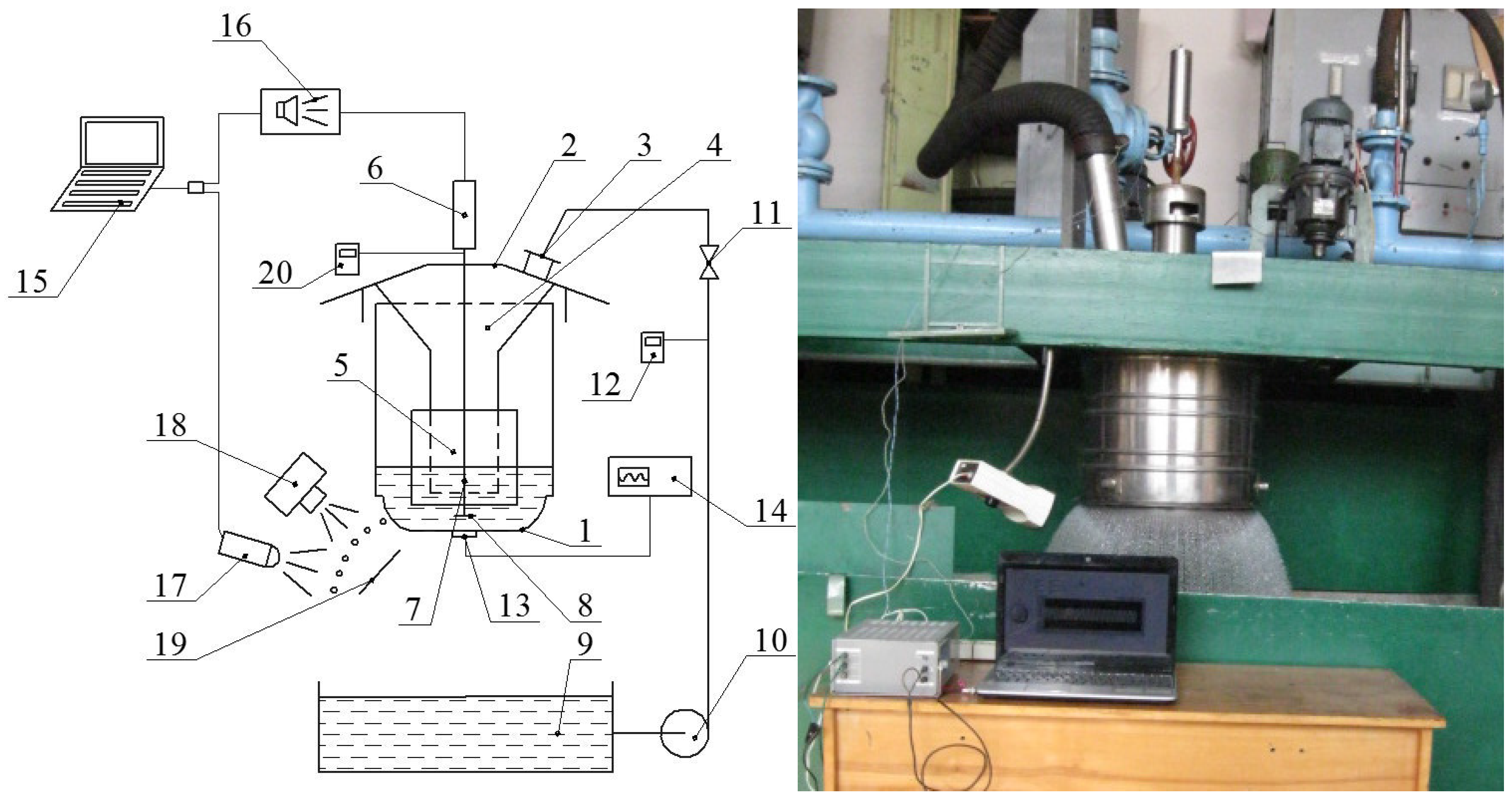
Ammonium nitrate (concentration 99 wt.%) melt at 174 °С and water at ambient condition were used in the experiments. Disintegration of both the water and the melt was investigated using stroboscopic light and a high-speed camera. It was reported that ammonium nitrate melt and water had shown similar behavior during the disintegration [26,27,28]. The experimental setup is shown in Figure 1. Study of the efflux was conducted at a single hole in a thin wall vessel.
Table 1 shows the specification of experimental setup.
Fluid is pumped from the buffer tank to the granulator nozzle. The liquid flow rate is controlled by the liquid flow meter (Metran 370). A filter is used to separate the liquid from solid impurities. The liquid level is regulated with a level gauge (Metran 100). Due to the hydrostatic pressure created by the liquid level in the perforated bottom vessel, liquid outflows from the holes. A computer program generates a signal, which is transmitted to the electromagnetic vibrator (the magnetostrictive actuator) after passing the low-frequency amplifier, making the resonator produce vibrations. The disc oscillator is positioned above the central part of the inner perforated bottom surface with a gap relative thereto. The gap provides a good hydrodynamic connection between the disc oscillator and the central part of the perforated bottom, through which waves spread in the melt in the form of elastic strains and enter the perforated bottom (Figure 2). The frequency of the perforated bottom vibrations is fixed with the vibration sensor (DN-3M1 and device PKV-02).
A stroboscope was employed for visual monitoring of the jet disintegration into droplets, and an applied frequency signal was synchronized with the wave generator. Near the jet exit from the granulator perforated bottom, there was a screen with changeable scales (with different grading) to determine the length of the jet that is not disintegrated, the diameter of the droplets formed after jet disintegration, and the distance between the droplets. A camera is located above the jet and the screen, and has a scale to monitor the jet disintegration into droplets. These pictures were analyzed by objects detection method with the search of round shapes and a software package for solving the tasks of technical computing (Matrix Laboratory). This method enables one to determine droplet sizes, the distance between them and other parameters of the jet disintegration [29]. In order to investigate the effects of vibration on the jet breakup phenomenon and further illustrate the monondisperse droplets production process, three predetermined variables related to vibration were studied, namely: liquid level (proportional to the rate of the liquid efflux from the hole), amplitude, and frequency of the forced signal. These variables are shown in Table 1. As mentioned earlier, due to the similarity of jet disintegration in water and glycerin, water disintegration was a main concern. One way to obtain forced perturbations of a liquid jet is to spread regular pressure pulses in a jet. As an option, the source of such pulses can be a disc oscillator (oscillating membrane), which produces vibrations.
3. Mathematical Model
When imposing vibrations, the disc oscillator performs a reciprocating motion and moves a quantity of liquid at one turn:
Consequently, regular perturbations in the form of contraction and expansion are imposed on the jet, outflowing from the hole and then breaking up into monodispersed drops in the locations of contraction.
The value is an important criterion of the transmission efficiency of the vibrations on the perforated bottom. The pressure vibration value that takes place in this case depends on the path velocity and amplitude of the disc. The key parameter of vibration dispersion is vibration frequency which affects the law of variation , allowing to adjust the average diameter and monodispersity range of the received drops at the time of the forced jet disintegration.
In general, the equations of viscous fluid motion [30,31,32] are used to calculate the hydrodynamic characteristics of the jet outflowing from the hole of the free surface. For simplicity and convenience, the Navier–Stokes equations describing liquid motion (jet outflow from the hole) in cylindrical coordinates are employed. It is assumed that the perturbations on the jet surface emerge under conditions of axially symmetric flow with zero tangential velocity. Such waves are called symmetric. In symmetric waves, the jet section is circular and there would be only contraction and expansion zones.
For numerical investigation and determination of the mechanism of velocity fluctuations and distribution of liquid vibrations, as well as pressure changes of outflowing jet from the perforated bottom hole, equations describing the non-stationary motion of liquid [32] were used:
Considering the melt jet hydrodynamic parameters, and its outflow from the holes of the vibration granulator perforated shell, the solution of Equation (3) for the case of non-stationary efflux is of particular interest, taking into account the changes occurring over time. Using the method of separation of variables, one can solve Equation (3), and the following solution is obtained:
In the first equation, for determination of the pressure changes along the jet, one can include a function that depends on time. The form of this function can be determined from the boundary conditions, assuming that the coordinate’s origin is aligned with the center of the hole where the melt outflows. Then for :
Assuming that in the hole, where the liquid jet outflows, pressure fluctuations are:
Then substituting Equation (5) in (6), the pressure profile along the jet axis “z”, which depends on the initial and boundary conditions of the jet and the physical properties of the liquid, can be obtained:
Equation (7), which is a solution of transient two-dimensional Navier–Stokes equations describing liquid motion, enables one to analyze pressure changes in the jet. This analysis depends on the liquid position with respect to the outlet hole and time, which can be used to predict liquid jet disintegration into separate monodisperse droplets of a given size and to choose optimal parameters of the granulator vibratory system. The forced oscillations arise due to the movement of the shaft (Figure 2), which creates an alternating pressure in the vessel and holes for liquid outflow. Alternating pressure affects the mode of the liquid jet breakup. There are four well-known breakup modes: (a) Rayleigh breakup mode, (b) first wind-induced, (c) second wind-induced, and (d) atomization. In the Rayleigh breakup mode, the surface tension between fluids amplifies the surface perturbations and leads to drop formation, whose dimensions are more uniform and significantly larger than the jet diameter. Therefore, the basic approach in generating monodisperse droplets is operating in Rayleigh breakup mode. The size of the main fraction can be changed by changing the parameters of the forced signal (frequency and amplitude of the oscillations). The higher the frequency, the smaller the diameter of the main fraction would be (generally in a narrow range). To change the size in a wider range (e.g., from 1.4–2 mm), the holes at the bottom of the bucket should be changed.
4. Results and Discussion
The vibrations of the granulator bottom were recorded and displayed on a two-channel oscilloscope in the form of a sinusoidal function graph (subject to change depending on the signal parameters). A comparative analysis of the experimental results and theoretical calculations of Equation (7) showed a discrepancy. Analysis of the results indicated that a jet was influenced by a set of perturbations, which were caused by uncontrolled outside noise and granulator construction [33], which were difficult to control. To obtain the analytical dependence of pressure changes in the jet, taking into account the noise, one needs to add a component, considering vibrations, which are caused by the external noise. Then Equation (7) becomes:
When filling the granulator-perforated bottom with liquid to the level of 380 mm at a frequency of 380 Hz and an amplitude of 50 microns, there was a wave perturbation on the jet surface with the expansion and contraction areas. Disintegration of the jet resulted in the formation of monodisperse droplets with a radius of 1.092 mm. A barely noticeable contraction occurred within every 8–10 drops, which was dissipating almost completely and preserving the symmetry. Droplet satellites were formed in the places of contractions.
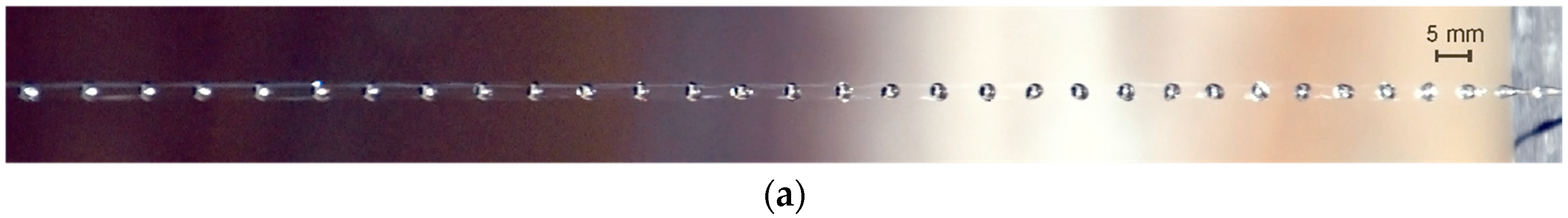
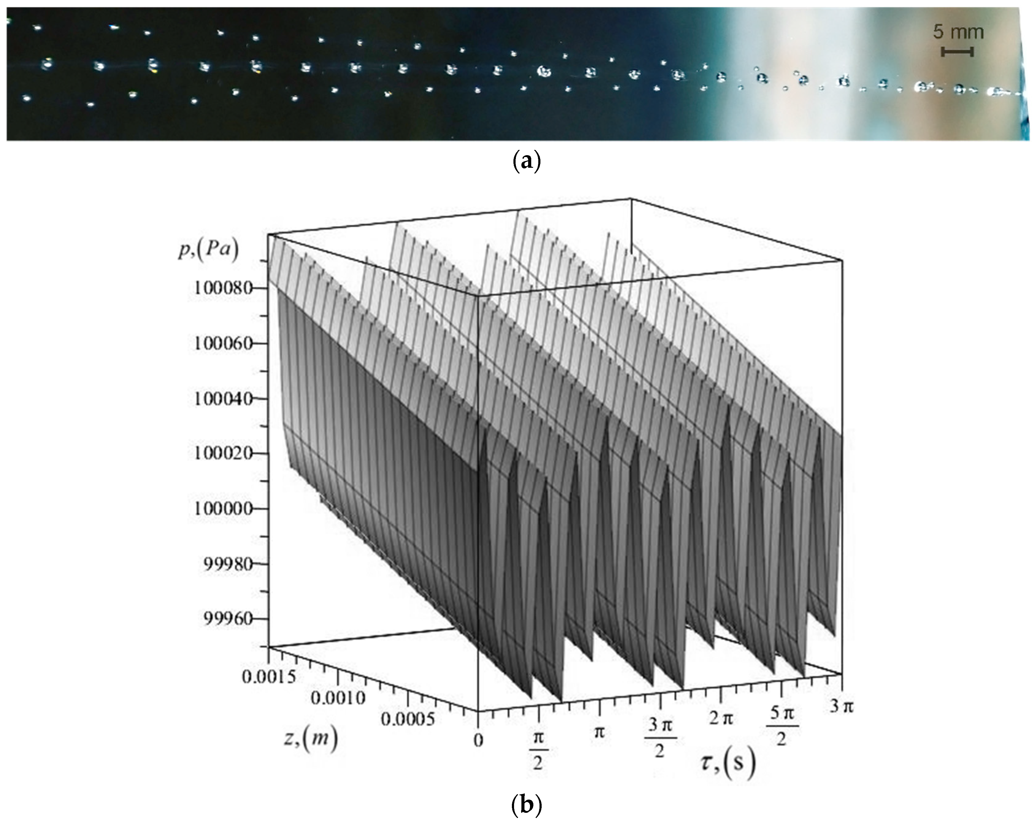
By keeping the hydro-mechanical process parameters of the forced jets disintegration and increasing only the signal amplitude up to 100 microns, the contraction disappears and the mode of monodisperse jet disintegration prevails without satellite formation (Figure 3a). When calculating pressure changes along the jet axis, one can observe pressure changes without any appreciable deviations (Figure 3b).
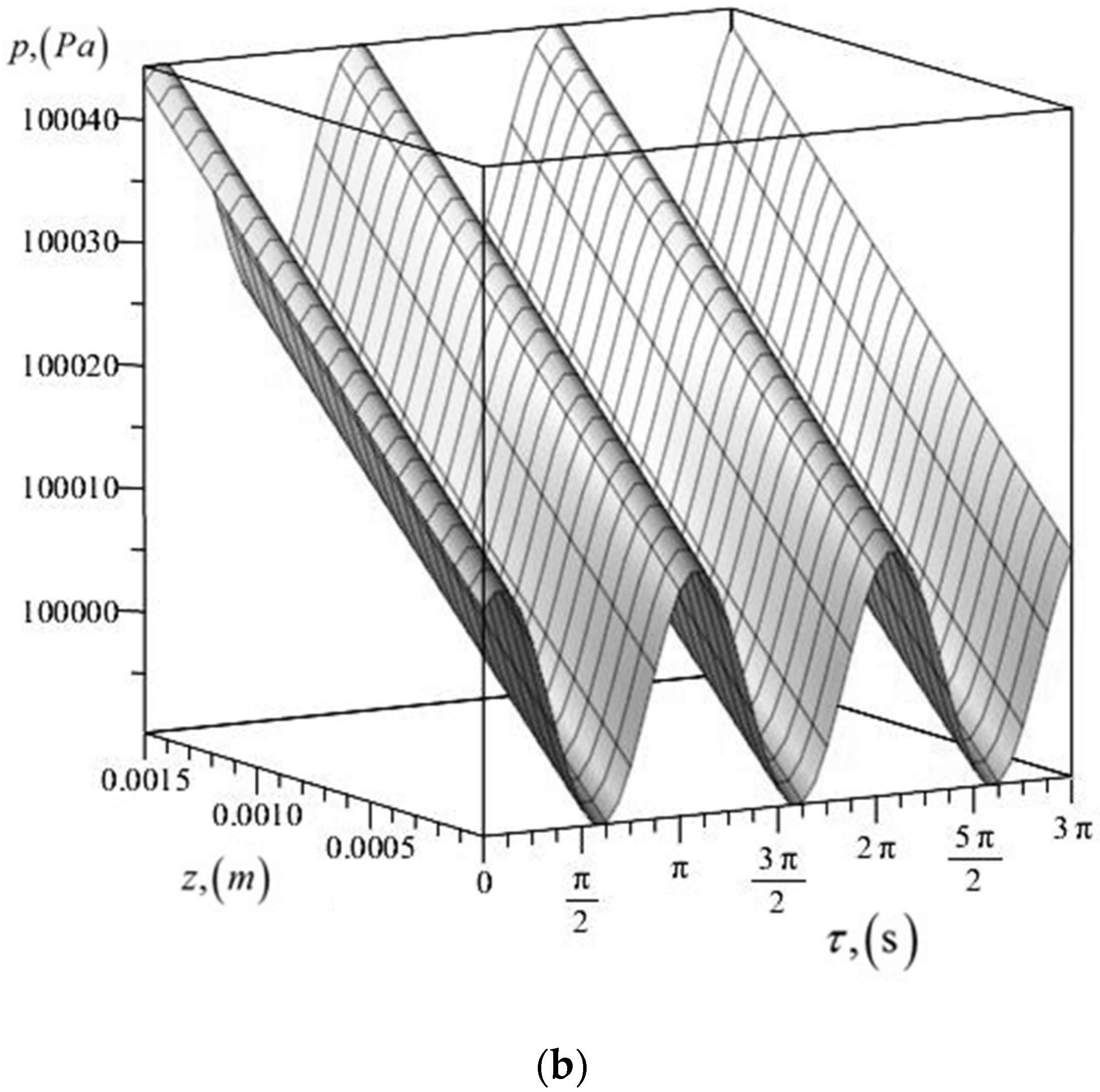
At the liquid level of 280 mm and the forced signal with an amplitude of 100 microns and frequency of 220 Hz, the jet disintegrated into droplets due to contraction, and satellites formed after breaking (Figure 4a). When analyzing perturbations on the surface of the jet, one can observe non-stationary changes of pressure along the jet. Pressure increases and decreases, which corresponds to the jet disintegration mode with the formation of satellites (Figure 4b).
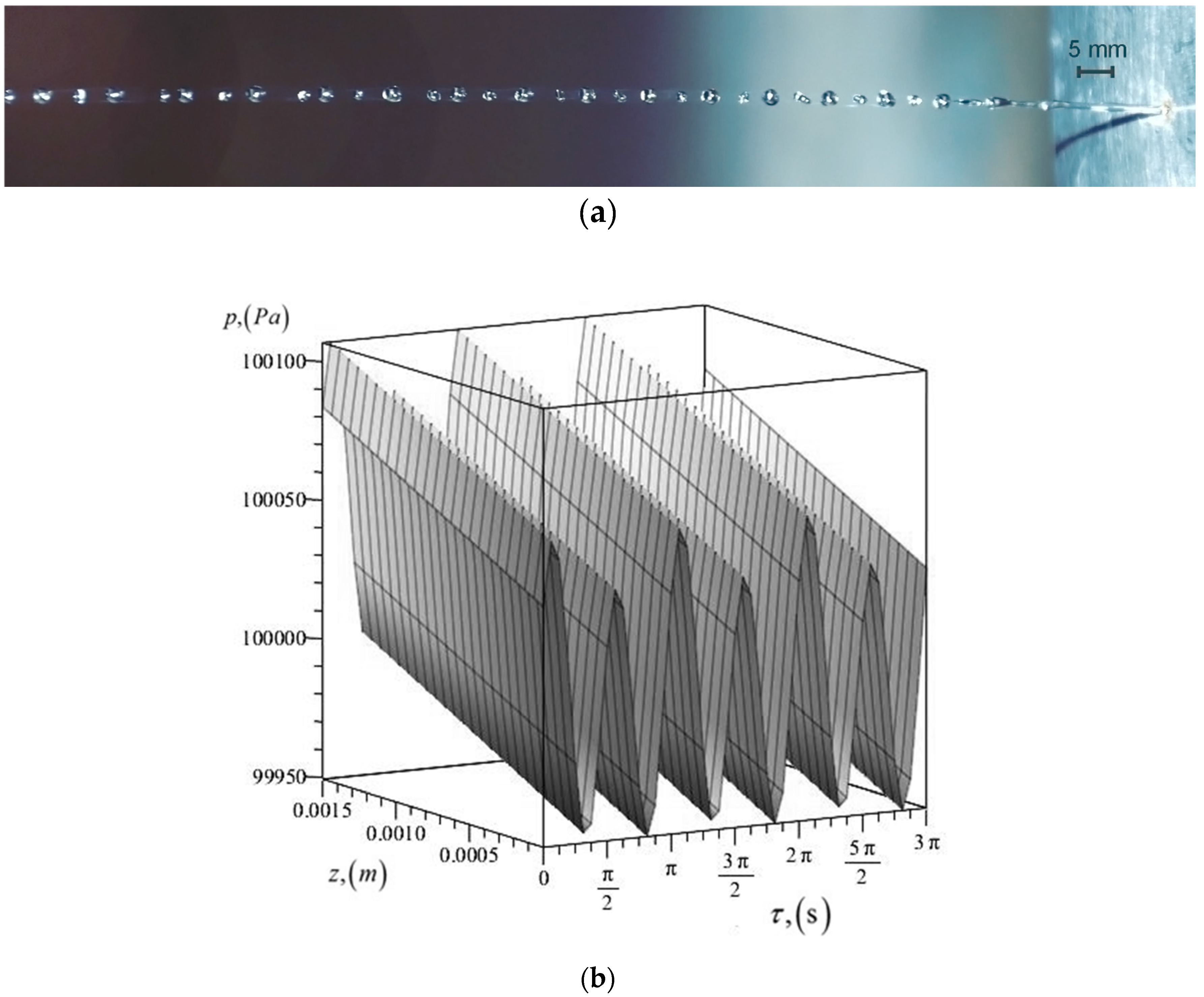
However, when the frequency was increased to 800 Hz, a polydisperse mode of jet disintegration occurred independent of signal amplitude (50–100 microns), as shown in Figure 5a. This phenomenon was also observed theoretically when pressure variation along the jet was calculated, as shown in Figure 5b.
The results of the present analysis and the experimentally determined data were in good agreement. Established regularities of the liquid jet controlled disintegration into droplets were tested during the development of the rotating vibratory priller. The forced signal frequency improved monodisperisity of the prills in a narrow range, depending on the melt level of the liquid level on the priller. Similar results have been reported elsewhere [34,35].
5. Industrial Test
The findings in this study were adopted in a test run in a commercial-size prilling tower for production of ammonium nitrate in Cuba.
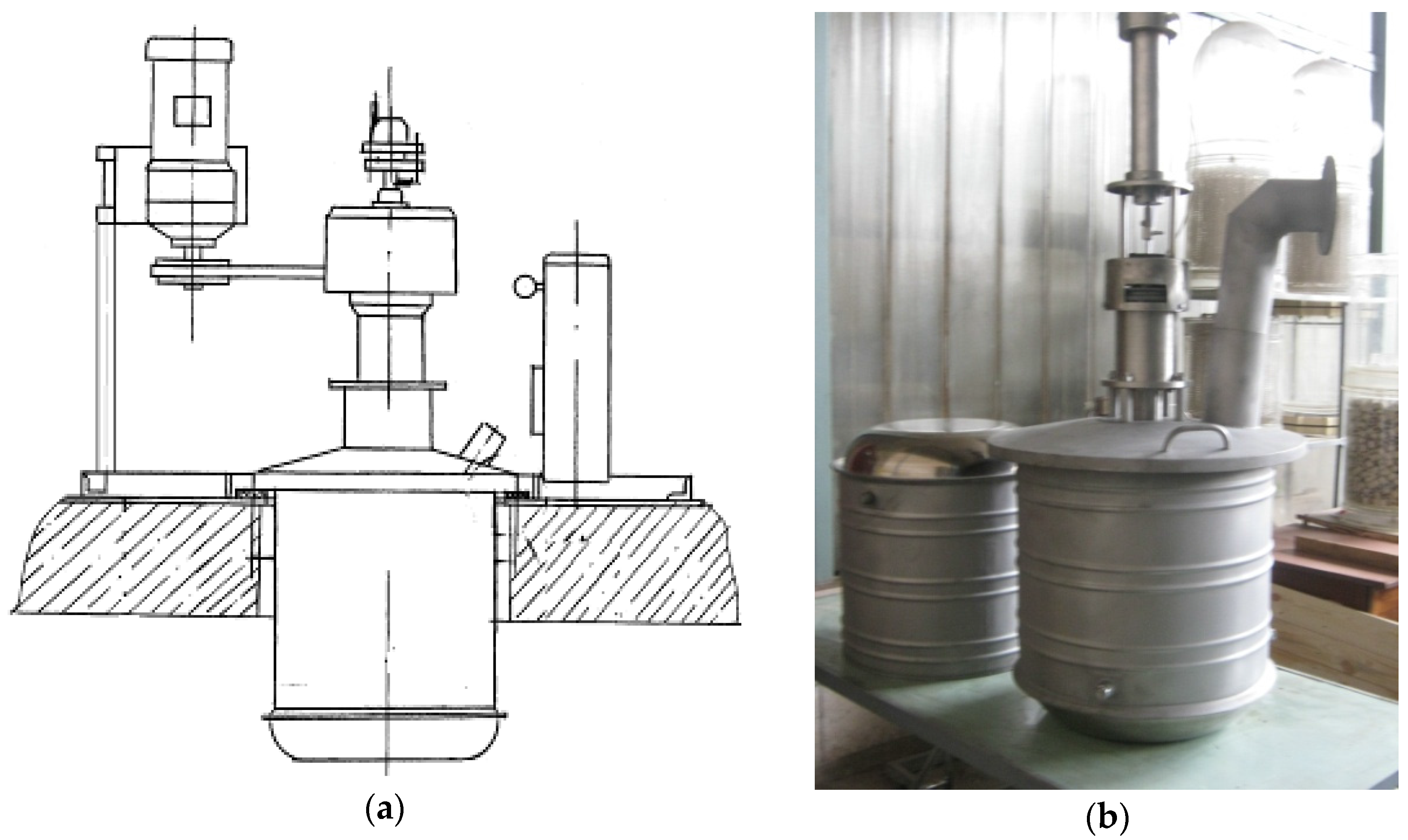
As shown in Figure 6, the commercial prilling tower has a diameter of 16 m and an effective height of 30 m. There is a priller on top of the tower, which rotates and disperses ammonium nitrate across the tower (Figure 7). The existing technological scheme was improved by installing new equipment after considering the findings in this study, including a modified rotating vibratory priller (Figure 7a), a transmission equipped with a motor-reducer (belt drive) frequency converter for induction motors (to change the speed of a rotary priller), and a vibratory system (generator of low frequency, control unit magnetostrictive actuator).
Priller rotation disperses the droplets on different trajectories, thus improving heat transfer conditions in the tower, and also increasing the resulting product’s monodispersity. Under the influence of gravitational forces, the obtained drops move downward, solidify and become prills as a result of heat transfer to the air flowing counter currently. At the bottom of the tower, almost along the entire cross-section, there is a built-in fluidized bed cooler using ambient air. Additional openings are available on top of the fluidized bed to supply additional air if needed. The operation details are summarized in Table 2.
Industrial tests were conducted according to the following procedure:
- Samples of ammonium nitrate were taken from the bottom of the tower after passing the “fluidized-bed” cooler in a steady-state condition. Size distribution of the ammonium nitrate particles was determined.
- After sampling ammonium nitrate, the operation parameters of the granulator were changed, namely, the frequency of granulator housing rotation and the forced signal frequency.
- Samples were taken at each condition at steady-state operation and the size distribution was determined for each one.
- Exhaust air samples were taken at steady-state condition for determination of ammonium nitrate dust concentration.
Figure 9 shows the size range of the product obtained by two different granulators: the new developed priller and a previously operated priller.
The difference in the product size distribution and dust content in the exhaust air from the tower was determined by replacing the granulation unit; the working conditions of the old and new equipment of the granulation unit were the same.
6. Conclusions
The controlled disintegration of melt nitrogen fertilizers into relatively monodispersed droplets was achieved using a vibratory granulator. The vibration frequency was found to have a profound effect on the production on monodispersed particles. Consequently, the heat load on the tower will be close to the optimal value, as the particles are less prone to sticking on the tower wall, which in turn reduces energy consumption and material costs. Production of off-spec product will be reduced substantially. It will also benefit from the reduction of dust emissions of ammonium fertilizers into the atmosphere, which will improve the ecological situation of the production area.
The study provides the basis for technological and engineering works on developing the modernized rotary vibrational melt granulator. Application of the newly designed granulator on a commercial scale resulted in a substantial reduction of dust in the exhaust air (up to four times) to 36 mg /Nm3 (compared to the reported average value of 200–250 mg/Nm3), which was lower than the statutory emission limit values of ammonium nitrate dust in the air established in Europe (50 mg/Nm3), in the absence of any air pollution control equipment.
Author Contributions
Maksym Skydanenko and Vsevolod Sklabinskyi conceived and designed the experiments; and the remaining parts were equally shared by all the authors.
Conflicts of Interest
The authors declare no conflict of interest.
Nomenclature
| amplitude (m) | |
| variables, depending on the physical and chemical properties of the liquid | |
| phase shift of the system vibrations (rad) | |
| disc-oscillator diameter (m) | |
| outflowing jet diameter (m) | |
| formed drops diameter (m) | |
| hole diameter (m) | |
| disc vibration frequency (Hz) | |
| quantity of liquid (kg) | |
| distance that the disc runs in one turn (m) | |
| pressure in the jet (Pa) | |
| radial distance (m) | |
| disc speed (m/s) | |
| radial component of the velocity (m/s) | |
| axial component of the velocity (m/s) | |
| axial distance (m) | |
| Greek letters | |
| time (s) | |
| liquid density (kg/m3) | |
| kinematic fluid viscosity (m2/s) | |
| cyclic frequency (rad/s) |
References
- Food and Agriculture Organization of the United Nations. World Fertilizer Trends and Outlook to 2018; FAO: Rome, Italy, 2015. [Google Scholar]
- Bruynseels, J.P. Fluid Bed Granulation of Ammonium Nitrate and Calcium Ammonium Nitrate; Proc. of the Fertiliser Society, 1985; No. 235. [Google Scholar]
- Schoemaker, I.R.; Smit, A.C.M. Criteria for a Choice between Various Granulation and Prilling Technologies for Fertilisers, 1981; Paper read before the Fertiliser Society of London.
- Ammonium Nitrate: A Comparative Analysis of Factors Affecting Global Trade; United States International Trade Commission: Washington, DC, USA, 1998; Investigation No. 332–393.
- Laurent, B. Straight ammonium nitrate fertiliser granule-prillstabilisation: Theoretical possibilities. In Proceedings of the International Fertiliser Association Technical Conference, Chennai, India, 24–27 September 2002. [Google Scholar]
- Gezerman, A.O.; Corbacioglu, B.D. A New Approach to Cooling and Prilling during Fertilizer Manufacture. Int. J. Chem. 2011, 3, 158–168. [Google Scholar] [CrossRef]
- Mehrez, A.; Ali, A.H.H.; Zahra, W.K.; Ookawara, S.; Suzuki, M. Study on Heat and Mass Transfer During Urea Prilling Process. Int. J. Chem. Eng. Appl. 2012, 3, 347–353. [Google Scholar] [CrossRef]
- Wu, Y.; Bao, C.; Zhou, Y. An Innovated Tower-fluidized Bed Prilling Process. Chin. J. Chem. Eng. 2007, 15, 424–428. [Google Scholar] [CrossRef]
- Rahmanian, N.; Homayoonfard, M.; Alamdari, A. Simulation of urea prilling process: An industrial case study. Chem. Eng. Commun. 2013, 200, 1–19. [Google Scholar] [CrossRef]
- Muhammad, A.; Pendyala, R.; Rahmanian, N. CFD Simulation of Droplet Formation Under Various Parameters in Prilling Process. Appl. Mech. Mater. 2014, 625, 394–397. [Google Scholar] [CrossRef]
- Kjaergaard, O.G. Multiple-core encapsulation: Prilling. In Microencapsulation of Food Ingredients; Vilstrup, P., Ed.; Leatherhead Publishing: Surrey, UK, 2001; pp. 197–214. [Google Scholar]
- Kozlov, V.V.; Grek, G.R.; Litvinenko, M.A.; Litvinenko, Y.A.; Kozlov, G.V. Round jet in a transverse shear flow. Vestnik NSU Ser. Phys. 2010, 5, 9–28. (In Russian) [Google Scholar]
- Renardy, Y.; Renardy, M.; Assighaou, S.; Benyahia, L. Numerical simulation of drop retraction after a strain jump. Phys. Rev. E 2009, 79, 046323. [Google Scholar] [CrossRef] [PubMed]
- Chernyshev, A.K.; Levin, B.V.; Tugolukov, A.V. Ammonium Nitrate: Properties, Manufacturing, Usage; Moscow, “INFOCHIM”, Russia, 2009. (In Russian) [Google Scholar]
- Gezerman, A.O. A practical solution to abate emission of ammonium nitrate and ammonia during prilling and granulation processes. Int. J. Mod. Chem. 2012, 2, 57–63. [Google Scholar]
- Muhammad, A.; Pendyala, R.; Rahmanian, N. Analysis of flow of urea in a perforated rotating bucket: Single orifice case. J. Appl. Sci. 2014, 14, 1252–1258. [Google Scholar]
- Hashemi, N.; Nourai, F. Study on pollution prevention through an integrated process-environmental mode in a urea prilling tower. Environ. Model. Assess. 2006, 11, 243–250. [Google Scholar] [CrossRef]
- Saleh, S.N.; Barghi, S. Reduction of fine particle emission from prilling tower using CFD simulation. Chem. Eng. Res. Des. 2016, 109, 171–179. [Google Scholar] [CrossRef]
- Daborh, E.K. Production of mondisperse sprays. Rev. Sci. Instrum. 1967, 38, 502–506. [Google Scholar] [CrossRef]
- Van Hoeve, W.; Gekle, S.; Snoeijer, J.H.; Versluis, M.; Brenner, M.P.; Lohse, D. Breakup of diminutive Rayleigh jets. Phys. Fluids 2010, 22, 122003. [Google Scholar] [CrossRef]
- Vassalo, P.; Ashgriz, N. Satellite formation and merging in liquid jet breakup. Proc. R. Soc. Lond. A Math. Phys. Eng. Sci. 1991, 433, 269–286. [Google Scholar] [CrossRef]
- Eggers, J.; Villermaux, E. Physics of Liquid Jet. Rep. Prog. Phys. 2008, 71, 036601. [Google Scholar] [CrossRef]
- Eggers, J. Nonlinear dynamics and breakup of free-surface flows. Rev. Mod. Phys. 1997, 69, 865–930. [Google Scholar] [CrossRef]
- Gezerman, A.O.; Corbacioglu, B.D. New approach for obtaining uniform- sized granules by prilling process. Chem. Eng. Elixir Chem. Eng. 2011, 40, 5225–5228. [Google Scholar]
- Lee, T.; Chen, J.W.; Lee, H.L.; Lin, T.Y.; Tsai, Y.C.; Cheng, S.L.; Lee, S.W.; Hu, J.C.; Chen, L.T. Stabilization and spheroidization of ammonium nitrate: Co-crystallization with crown ethers and spherical crystallization by solvent screening. Chem. Eng. J. 2013, 225, 809–817. [Google Scholar] [CrossRef]
- Hjhg Cholin, B.G. Influence of the regular perturbations form of the liquid jet surface on its disintegration into droplets. Proc. USSR Acad. Sci. 1970, 194, 305–308. (In Russian) [Google Scholar]
- Cholin, B.G.; Segal, R.B.; Haysinskiy, Y.F. Long-wave monodisperse disintegration of a liquid jet. Proc. USSR Acad. Sci. 1980, 253, 1074–1076. (In Russian) [Google Scholar]
- Cholin, B.G. Centrifugal granulators and quality of ammonium nitrate granules. Chem. Ind. 1971, 2, 53–56. (In Russian) [Google Scholar]
- Cholin, B.G. Vibratory granulator for obtaining the granulated ammonium nitrate and carbamide. Chem. Ind. 1970, 3, 40–41. (In Russian) [Google Scholar]
- Hahn, B.; Valentine, D. Essential Matlab for Engineers and Scientists; Academic Press: Butterworth-Heinemann:, Italy, 2010. [Google Scholar]
- Crowe, C.T. Multiphase Flow Handbook; Taylor & Francis Group, LLC: New York, NY, USA, 2006. [Google Scholar]
- Kochin, N.E.; Kibel, I.A.; Rose, N.V. Theoretical Hydromechanics; Fizmatgiz, 1963; p. 2. (In Russian) [Google Scholar]
- Saleh, S.N.; Ahmed, S.M.; Al-mosuli, D.; Barghi, S. Basic design methodology for a prilling tower. Can. J. Chem. Eng. 2015, 93, 1403–1409. [Google Scholar] [CrossRef]
- Muhammad, A.; Rahmanian, N.; Pendyala, R. Flow analysis of melted urea in a perforated rotating bucket. Appl. Mech. Mater. 2013, 372, 340–345. [Google Scholar] [CrossRef]
- Wong, D.C.Y.; Simmons, M.J.H.; Decent, S.P.; Pǎrǎu, E.; King, A.C. Break-up dynamics and drop size distributions created from spiralling liquid jets. Int. J. Multiph. Flow 2004, 30, 499–520. [Google Scholar] [CrossRef]
Figure 1.
Experimental setup of the vibratory granulator: 1—perforated bottom; 2—housing; 3—nozzle; 4—collector; 5—filter element; 6—electromagnetic vibrator; 7—stock; 8—resonator (disc); 9—buffering capacity; 10—pump; 11—valve; 12—liquid flow meter (Metran 370); 13—vibration gauge; 14—oscilloscope; 15—computer; 16—low-frequency amplifier; 17—stroboscope; 18—photo camera; 19—screen with a scale; 20—level gauge (Metran 100).

Figure 2.
Schematic diagram of disc oscillator and perforated bottom vessel.
Figure 3.
Study results of the jet at a signal frequency of 380 Hz, and amplitude of 100 µm: (a) physical experiment; (b) theoretical calculation using Equation (8).
Figure 3.
Study results of the jet at a signal frequency of 380 Hz, and amplitude of 100 µm: (a) physical experiment; (b) theoretical calculation using Equation (8).


Figure 4.
Study results of the jet at a signal frequency of 220 Hz, and amplitude of 100 µm: (a) physical experiment; (b) theoretical calculation using the Equation (8).
Figure 4.
Study results of the jet at a signal frequency of 220 Hz, and amplitude of 100 µm: (a) physical experiment; (b) theoretical calculation using the Equation (8).

Figure 5.
Comparison between jet disintegration at the signal frequency of 800 Hz, and amplitude of 50 µm: (a) physical experiment; (b) theoretical calculation using Equation (8).
Figure 5.
Comparison between jet disintegration at the signal frequency of 800 Hz, and amplitude of 50 µm: (a) physical experiment; (b) theoretical calculation using Equation (8).

Figure 6.
Prilling tower: (a) schematic diagram; (b) photo, side view of the prilling tower.
Figure 7.
Rotating vibratory priller: (a) schematic diagram; (b) photo.

Figure 8.
Prills obtained during the tests.
Figure 9.
Comparison of size distributions of ammonium nitrate prills.

Table 1.
Operating condition/specification of the experimental setup.
| Operating Condition and Physical Properties of Liquid Feed (Water) | Feed inlet temperature, °C | 20 |
| Ambient Air temperature, °C | 20 | |
| Feed density, kg/m3 | 998 | |
| Feed Dynamic Viscosity, kg/(s·m) | 1.002 × 10⁻³ | |
| Feed surface tension, N/m | 72.75 × 10⁻³ | |
| Vibration Specification | Liquid level, mm | 280; 380 |
| Frequency, Hz | 220; 380; 800 | |
| Amplitude, µm | 50; 100 | |
| Hole Specification | Hole diameter, mm | 1.1 |
| Hole length, mm | 1 | |
| Hole material, steel | 321H (AISI) or 1.4878 (EN) |
Table 2.
Operating conditions and dimensions of the prilling tower.
| Operation Conditions: | |
| Feed inlet temperature, °C; | 180 |
| Prill temperature at the tower base cones, °C; | 110–120 |
| Max. air inlet temperature, °C; | 35 |
| Air outlet temperature, °C; | 45–50 |
| No. of exhaust fans, pcs | 4 |
| Air flow rate, m3/h; | 300,000–500,000 |
| Air velocity, m/s | 0.4–0.7 |
| There is fluidized bed at the tower base, yes | |
| Ammonium nitrate from its concentrated, wt.% | 99,5 |
| Tower dimensions: | |
| Effective tower height, m; | 30 |
| Tower diameter, m; | 16 |
| Rotor priller: | |
| Diameter of the priller, m; | 0.5 |
| Number of prillers, pcs | 1 |
| Number of holes in a priller, pcs | 2300 |
| Hole diameter, mm; | 1 |
| Hole length, mm; | 2 |
| Rotational speed of the priller, rpm; | 28–60 |
| Productivity of the priller, t/h; | 22–30 |
| There is a fusion filter before priller-yes. |
Table 3.
Results of industrial experiments.
| No. | Rotational Speed of Granulator | Productivity | Frequency | Size Range of Prills, % | Static Pressure | ||||||
|---|---|---|---|---|---|---|---|---|---|---|---|
| rpm | kg/h | Hz | <1 mm | 1.0–2.0 mm | 2.0–2.83 mm | 2.83–3.15 mm | 3.15–4.0 mm | 4.0–6.0 mm | 2.0–4.0 mm | kPa | |
| 1 | 33 | 25,000 | 0 | 3.8 | 13.35 | 75.2 | 6.8 | 0.45 | 0.4 | 82.45 | 3.1 |
| 2 | 33 | 25,000 | 0 | 0.9 | 9.85 | 86.0 | 2.5 | 0.75 | 0 | 89.25 | 3.2 |
| 3 | 33 | 24,000 | 0 | 1.2 | 11.8 | 83.45 | 2.75 | 0.8 | 0 | 87.0 | 3.1 |
| 4 | 33 | 20,000 | 0 | 2.8 | 11.75 | 80.45 | 4.5 | 0.5 | 0 | 85.45 | 1.2 |
| 5 | 33 | 20,000 | 0 | 2.5 | 14.55 | 78.2 | 3.9 | 0.85 | 0 | 82.95 | 1.1 |
| 6 | 33 | 20,000 | 0 | 2.2 | 17.75 | 75.55 | 3.75 | 0.75 | 0 | 80.05 | 1.1 |
| 7 | 33 | 21,000 | 0 | 2.2 | 9.55 | 84.4 | 3.2 | 0.65 | 0 | 88.25 | 1.1 |
| 8 | 33 | 21,000 | 0 | 2.55 | 9.75 | 82.6 | 3.5 | 1.25 | 0.25 | 87.45 | 1.2 |
| 9 | 33 | 20,000 | 0 | 2.6 | 12.1 | 80.65 | 4.25 | 0.4 | 0 | 85.30 | 1.3 |
| 10 | 33 | 22,000 | 0 | 1.95 | 4.2 | 86.9 | 5.55 | 1.4 | 0 | 93.85 | 1.5 |
| 11 | 33 | 23,000 | 320 | 1.9 | 8.4 | 80.0 | 8.25 | 1.45 | 0 | 89.70 | 2.0 |
| 12 | 48 | 23,000 | 340 | 0.85 | 3.95 | 94.35 | 0.85 | 0 | 0 | 94.20 | 2.5 |
| 13 | 60 | 24,000 | 340 | 1.4 | 5.65 | 92.1 | 0.85 | 0 | 0 | 92.95 | 2.5 |
| 14 | 60 | 24,000 | 400 | 0.0 | 8.4 | 91.30 | 0.3 | 0.0 | 0.0 | 91.60 | 2.5 |
| 15 | 60 | 23,000 | 400 | 0.45 | 27.1 | 71.85 | 0.6 | 0 | 0 | 72.45 | 2.5 |
| 16 | 60 | 23,000 | 440 | 0.5 | 40.45 | 57.65 | 0.85 | 0.55 | 0 | 59.05 | 2.5 |
| 17 | 60 | 23,000 | 460 | 0.5 | 50.6 | 47.8 | 0.9 | 0.2 | 0 | 48.90 | 2.4 |
© 2017 by the authors. Licensee MDPI, Basel, Switzerland. This article is an open access article distributed under the terms and conditions of the Creative Commons Attribution (CC BY) license (http://creativecommons.org/licenses/by/4.0/).
Share and Cite
MDPI and ACS Style
Skydanenko, M.; Sklabinskyi, V.; Saleh, S.; Barghi, S. Reduction of Dust Emission by Monodisperse System Technology for Ammonium Nitrate Manufacturing. Processes 2017, 5, 37. https://doi.org/10.3390/pr5030037
AMA Style
Skydanenko M, Sklabinskyi V, Saleh S, Barghi S. Reduction of Dust Emission by Monodisperse System Technology for Ammonium Nitrate Manufacturing. Processes. 2017; 5(3):37. https://doi.org/10.3390/pr5030037
Chicago/Turabian StyleSkydanenko, Maksym, Vsevolod Sklabinskyi, Saad Saleh, and Shahzad Barghi. 2017. "Reduction of Dust Emission by Monodisperse System Technology for Ammonium Nitrate Manufacturing" Processes 5, no. 3: 37. https://doi.org/10.3390/pr5030037
Note that from the first issue of 2016, this journal uses article numbers instead of page numbers. See further details here.