Investigation of the Porosity Distribution, Permeability, and Mechanical Performance of Pervious Concretes

Geotechnical and Structural Engineering Research Center, Shandong University, Jinan 250061, China
*
Author to whom correspondence should be addressed.
Processes 2018, 6(7), 78; https://doi.org/10.3390/pr6070078
Submission received: 18 May 2018
/
Revised: 19 June 2018
/
Accepted: 20 June 2018
/
Published: 26 June 2018
(This article belongs to the Special Issue Fluid Flow in Fractured Porous Media)
Abstract
:Pervious concrete is a kind of porous and permeable material for pavements and slope protection projects, etc. In this paper, a kind of pervious concrete was prepared with Portland cement, silica fume (SF), polycarboxylate superplasticizer (SP), and limestone aggregates. The performance of concrete, such as its porosity, pore distribution, permeability coefficients, and mechanical properties, were studied through laboratory tests. The volumetric porosity was measured by the water displacement method, and the planar porosity and pore size distribution were determined using image processing technology. A permeameter with a transparent sidewall and an exact sidewall sealing method were used to measure the permeability coefficients accurately. The results show that the segregation index and flow values of pastes increased with the increase of SP and water cement ratio (W/C). The measured porosity (volumetric porosity and planar porosity) of pervious concrete with a single-size aggregate was closer to the design porosity than that with the blended aggregate. Compared with the design porosity selected in this study, aggregate size was the main factor influencing the pore distribution of pervious concrete. The standard deviation of the permeability coefficient was less than 0.03 under different hydraulic gradients. It was found that the relationships between the permeability coefficient and volumetric porosity (or effective pore size d50) approximately obey polynomial function. Based on the test results, the optimized parameters were suggested for practical engineering: W/C of 0.26–0.30; 0.5% SP content; 5% SF content; 15–21% design porosity; and aggregate sizes of 4.75–9.5 mm and 9.5–16 mm.
1. Introduction
With the rapid development of economy and the increment of urban populations, many large-scale infrastructures and impermeable roads have been built, which has caused more and more serious environmental problems, such as urban hot island phenomena and the disappearance of groundwater. Pervious concrete, also referred to as porous ecological concrete, is a porous media material which consists of cement, water, aggregates, and admixtures, etc. Pervious concrete has a large porosity and its permeability can reach up to about 2–6 mm/s [1]. Rainwater can penetrate into pervious concrete quickly, so groundwater can be replenished and stored effectively. It can also reduce city temperatures and alleviate urban hot island phenomena [2].
Pervious concrete was first invented in Britain in 1824. It was first introduced into the United States in the mid-1970s and has since been rapidly developed [3]. The Sponge City was introduced in China in approximately 2012. Because of its huge environmental benefits, it was quickly and widely emphasized and generalized in the construction of China’s Sponge City. To date, the properties of pervious concretes have been studied in many laboratories, including mixing design, conservation method, porosity characteristics, strength and durability, etc. [4,5,6]. Compared with traditional or common concrete, pervious concrete has an amount of porosity and pore structure features, which have been proven to have a great influence on the properties of pervious concretes [7,8]. Montes et al. [9] recommended using the water displacement method, based on Archimedes buoyancy principle, to obtain porosity. Neithalath et al. [8] used image analysis to analyze the pore structure features of pervious concrete. The permeability of pervious concrete is high due to the presence of high porosity, and the test methods of the permeability coefficient are especially important [10,11]. Kayhanian et al. [12] used a National Center for Asphalt Technology’s (NCAT) falling head permeameter to evaluate the permeability coefficient of pervious concrete. Montes et al. [13] evaluated permeability by using a falling head permeameter system. The system could register the total volume flowing out of the permeable material per second. At the same time, Jiang Zhengwu and Yang et al. [13,14] showed that porosity, W/C, aggregate cement ratio, and aggregate size were the main factors influencing the permeability and strength of pervious concrete. William et al. [15] studied the effect of vertical porosity distributions on the permeability coefficient. Because of the low strength of the pervious concrete prepared by common materials and methods, various admixtures and fine aggregates were introduced to expand the application scope of pervious concrete. Yang and Jiang [16] used fine aggregates, organic intensifiers, and optimized mix proportions to produce a high strength pervious concrete. Huang [17] improved the compressive strength of pervious concrete by using polymer modification and sand.
Although many researches on pervious concretes have been conducted, studies concerning the properties of paste, as well as the accurate determination of the permeability coefficient and pore structure, are still limited. The rheological property of cement paste is one of the key factors responsible for the preparation of good pervious concrete [18,19]; however, it has not been studied sufficiently. Besides, when the permeability coefficient of pervious concrete is measured, the fluid leakage through the specimen-permeameter interface is not given significant attention. In this paper, the influences of polycarboxylate superplasticizer (SP), silica fume (SF), and W/C on the fluidity of cement pastes and the segregation index of pervious concretes were discussed in detail. The effect of design porosity and aggregate size on the porosity distribution of pervious concrete was studied. A visual permeameter and an exact sidewall sealing method were established to measure the permeability coefficients accurately. The mechanical behavior, such as the compressive strength, was also measured.
2. Materials and Test Methods
2.1. Materials
P.O 42.5 ordinary Portland cement was provided by Sunnsy Group, Jinan, China, and its chemical composition ingredients are shown in Table 1. Silica fume (SF) was provided by Elkem Company, Oslo, Norway, and its chemical composition is presented in Table 1. The polycarboxylate superplasticizer (SP) was provided by Shandong Academy of Building Research, Jinan, China, and the main properties of NC-J are shown in Table 2. According to the standard of CJJ/T135-200, the literature [13,20] and requirements of construction projects, limestone gravel was used as an aggregate, and aggregate sizes followed those listed in Table 3.
2.2. Test Methods
2.2.1. Fluidity
The fluidity of cement paste was tested according to GB/T8077-2012. The truncated cone mold had a top diameter of 36 mm, a bottom diameter of 60 mm, and a height of 60 mm. Different SP contents (0.3%, 0.5%, and 0.7%), SF contents (5% and 10%), and W/C (0.22–0.32) were used to prepare the cement pastes. Then, the paste was poured into truncated cone mold which was placed on a glass pane. Next, the truncated cone mold was removed from the glass pane. The diffusion diameter of the paste was measured with a ruler in an orthogonal direction after 30 s. The average flow value was the initial diffusion diameter of the paste.
2.2.2. Mix Proportions
The mix proportion of pervious concrete was designed by the absolute volume method according to CJJ/T135-2009. The cement (mc), water (mw), and admixture (mj) were calculated as follows:
where mg is the mass of the aggregate; , , , are the apparent densities of aggregate, cement, water, and admixture, respectively; and P is the design porosity.
In the segregation tests of pervious concrete, the aggregate size was 4.75–9.5 mm and the design porosity was 15%. The W/C, SP, and SF were shown in the fluidity test.
In the porosity distribution tests, permeability tests, and mechanical performance tests of pervious concrete, the aggregate sizes were as shown in Table 3. The design porosities were 12%, 15%, 18%, 21%, 24%, and 27%; W/Cs were 0.24–0.32. The SP content was 0.5%. The SF content was 5%. As an example, the parameters of pervious concrete with a W/C of 0.28 are shown in Table 4.
2.2.3. Molding and Curing
Concrete specimen preparation procedures were as follows. Firstly, the aggregate and 70% water were mixed for 60 s. Then, the 50% cement and admixture were mixed for another 60 s. The remaining cement and water were added and mixed for 2 min. In order for the material to uniformly fill in the mold, fresh concrete was divided into two layers into the mold. Each layer of concrete was vibrated for 20 s on the vibration table, and then the concrete was compacted with 0.08 MPa compressive stress. After molding, the specimen was placed in a curing box at 20 °C with a relative humidity of 97%. The specimen was removed from the mold after 24 h, and then placed in a curing box for 3 days, 7 days, or 28 days.
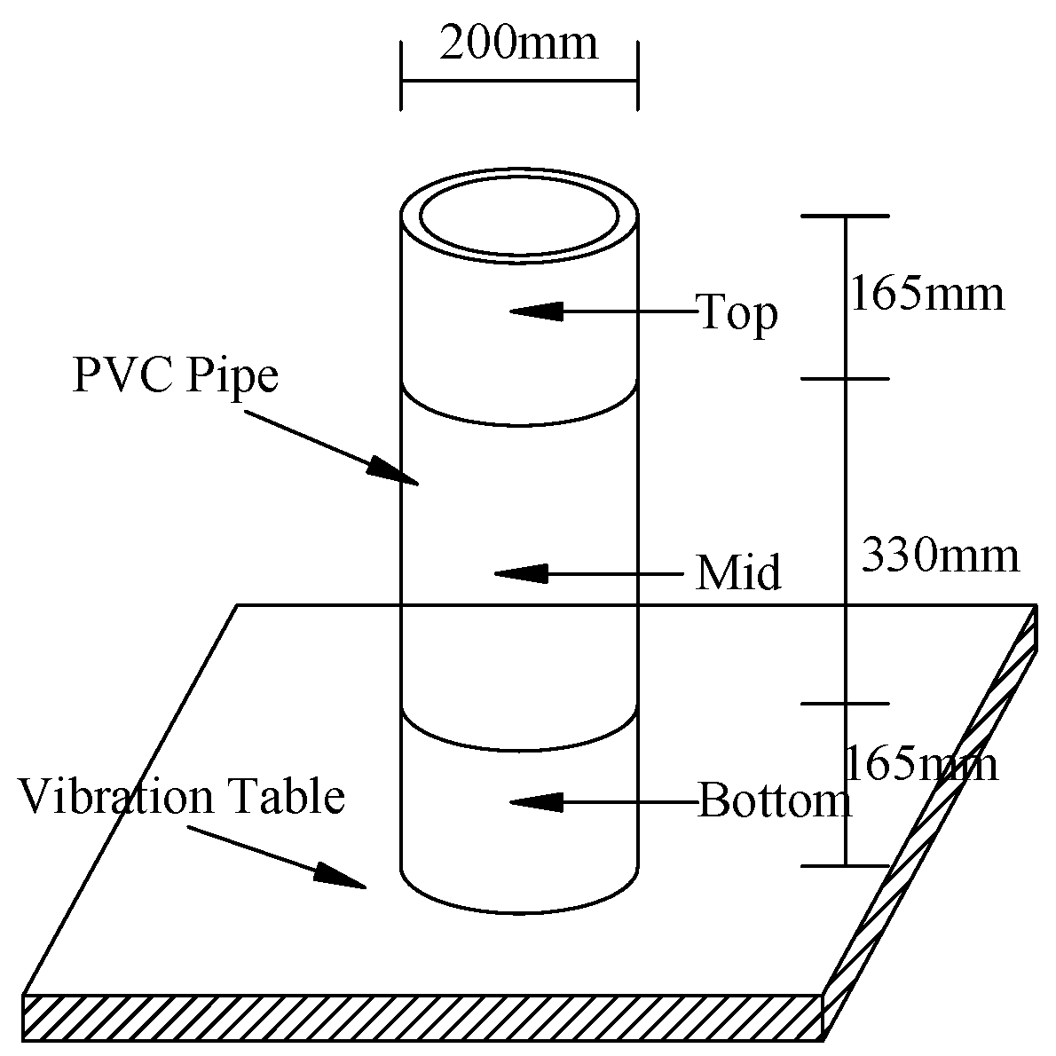
2.2.4. Segregation Index
The segregation index of the concrete was evaluated according to ASTMC1610; the test device is shown in Figure 1. The specimen was produced in a polyvinyl chloride (PVC) tube. The mass of the specimen in the top section of the column (mt) and the mass (mb) in the bottom section were measured after vibrating for 2 min on a vibration table. The segregation index (S) was calculated as follows:
2.2.5. Porosity
The volumetric porosity was measured by the water displacement method. The specimen was dried in a drying box at 110 °C for 24 h, and then put into water for 24 h, so the volume of the water (Vd) repelled by the specimen was acquired. The volume of open pores was calculated by subtracting Vd from the sample bulk volume (Vb) [21]. The volumetric porosity of the specimen was calculated as follows:
2.2.6. Pore Structure Features
The pore structure of pervious concrete was analyzed by Image-Pro Plus 6.0. For a concrete specimen, three to five cylinders were used, and the diameter and height of the specimen were 110 mm and 160 mm, respectively. In the process of the pore structure test, first of all, the specimen was sectioned into 20 mm thick slices. The surface of the specimen was grinded to obtain a flattened surface. An image of surface was captured by a camera, and the outer region of this image was cut to avoid edge effects. Finally, the image was processed by Image-Pro Plus 6.0 software, and an appropriate threshold was chosen to obtain the pore size distribution and planar porosity, according to Reference [8].
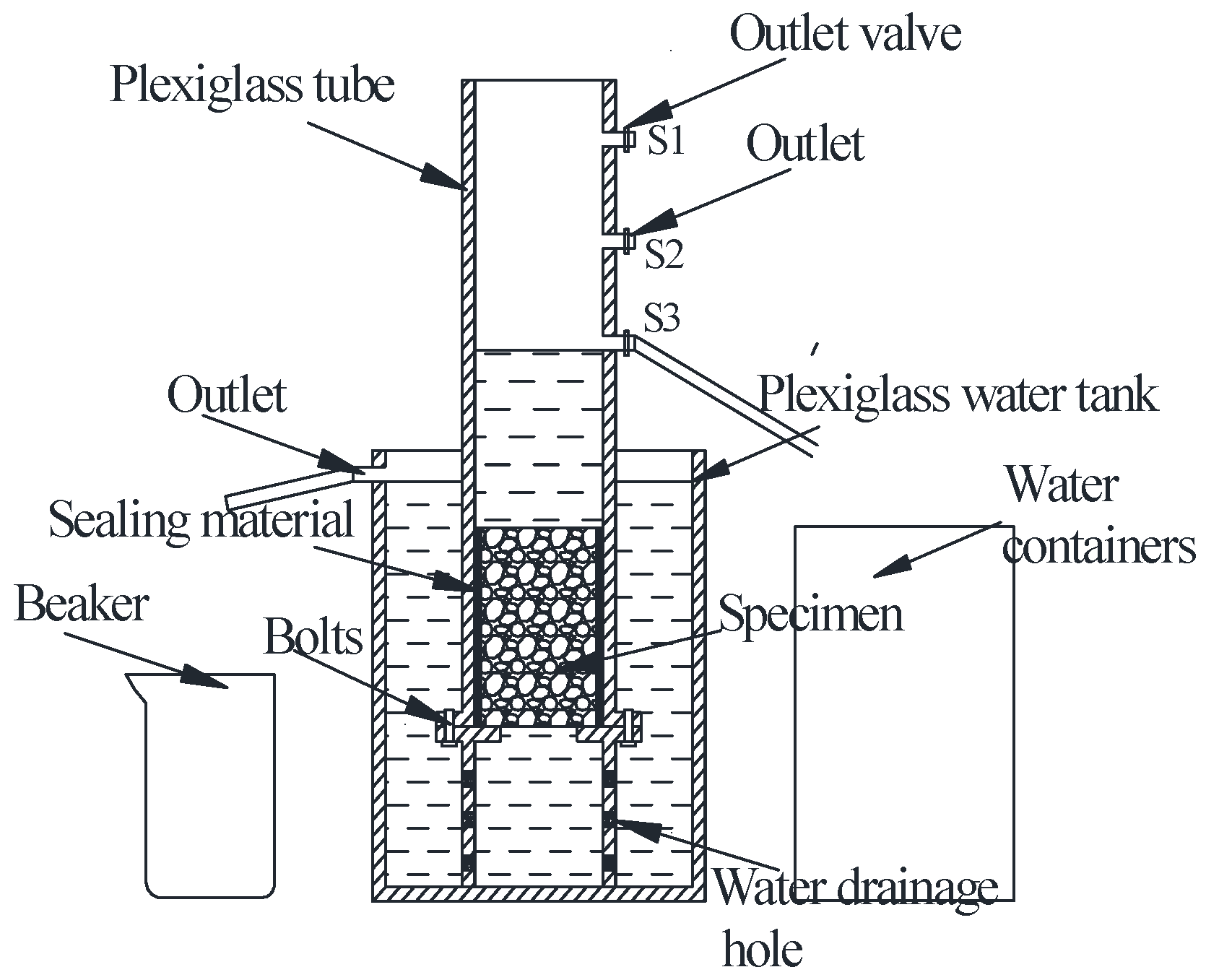
2.2.7. Permeability Coefficient
The permeability coefficient was measured by the permeameter that was designed with transparent plexiglass by our group. As shown in Figure 2, three outlets at different heights of the permeameter were installed to create different hydraulic gradients. The heights of the three outlets were 10 cm, 15 cm, and 20 cm. For a concrete specimen with same mix proportions, three cylinders were prepared, and the diameter and height of the specimen were 110 mm and 120 mm, respectively. In the process of the permeability test, the specimen was put into the permeameter, and the sidewall space between the specimen and the permeameter was sealed with Vaseline and transparent wrapping film, so it was easy to know whether there was sidewall leakage. Each specimen was tested three times under different hydraulic gradients to ensure the accuracy of the results. The permeability coefficient of pervious concrete K was calculated by Darcy’s law as follows:
where h is the specimen height (cm); H is the hydraulic gradient (cm); and A is the specimen area (cm2).
2.2.8. Mechanical Strength
The flexural strength and compressive strength of the pervious concrete were tested according to GB/T 50081-2002. The size of the specimen used in the compressive strength test was 100 mm × 100 mm × 100 mm. The size of the specimen used in the flexural strength test was 100 mm × 100 mm × 400 mm. The mechanical strength of the specimen reached 70% of its peak strength during the test, after which the test was stopped. The compressive strength and flexural strength were tested after 3 days, 7 days, and 28 days.
3. Results, Analysis, and Discussion
3.1. Fluidity Performance
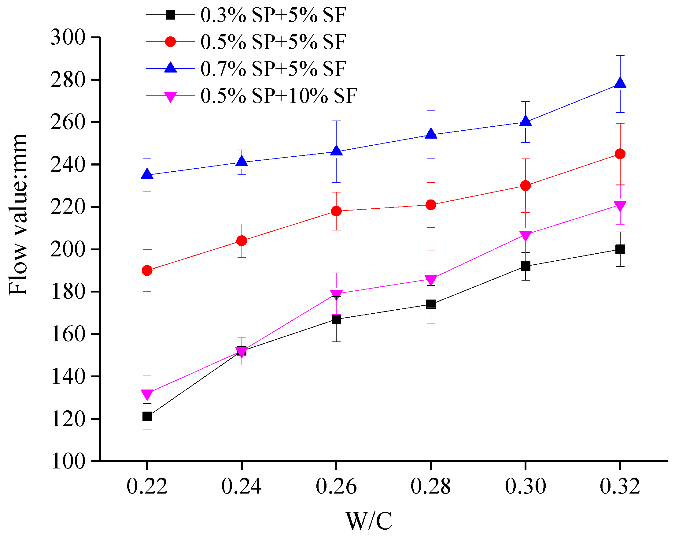
Figure 3 shows the measured flow values of pastes with different dosages of SP, SF, and W/C.
It can be seen in Figure 3 that the flow values linearly increased with increase of the W/C. SP was usually added to improve the fluidity of the paste at a low W/C. The use of SP significantly affected the flow values of the pastes; a small increase of SP could make the flow value of paste reach the desired value under a lower W/C. SF was introduced to improve strength of pervious concrete. However, because of the smaller particle size and large specific surface area of SF, the flow values of pastes significantly decreased when the content of SF increased.
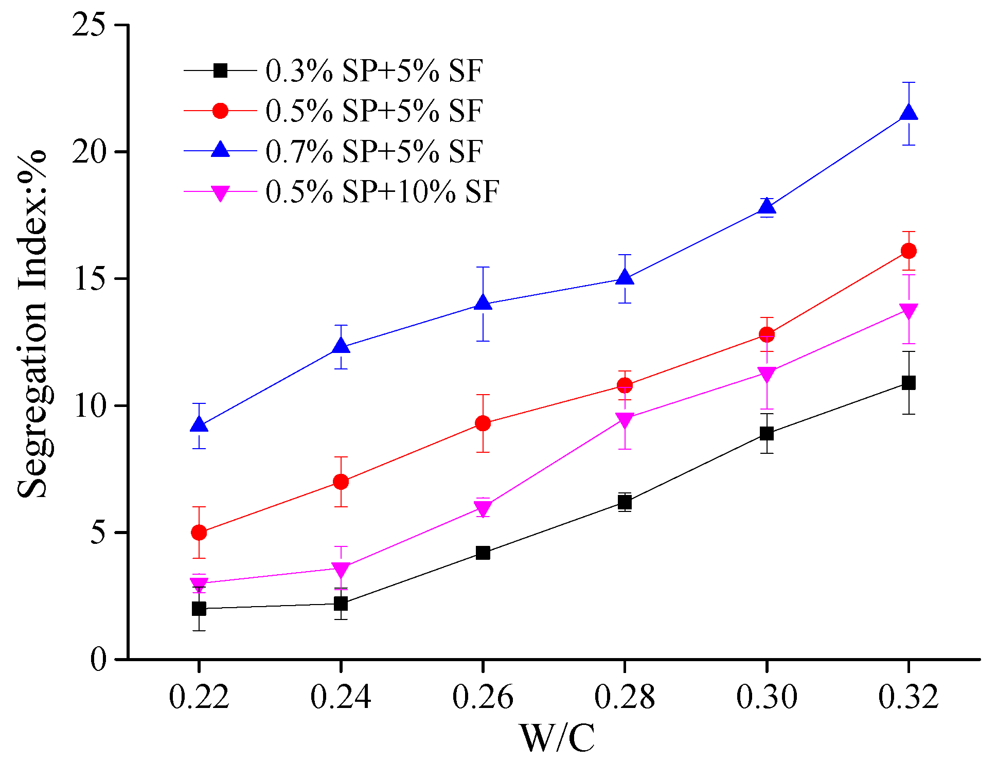
Figure 4 shows the effect of SP, SF, and W/C on the segregation index of pervious concretes, for which a 4.75–9.5 mm aggregate size was used.
In Figure 4, it was obvious that the segregation index increased as the W/C increased. When the W/C was constant, an increase of SP and a decrease of SF also increased the segregation index. The segregation index of pervious concrete with 0.7% SP and 5% SF was the largest. This was mainly related to the flow value of the paste; the increase of the flow value of the paste can increase the segregation index. Moreover, it also can be seen from Figure 3 and Figure 4 that the effects of the W/C on the flow value of the paste and segregation index of pervious concretes were found to be not so obvious compared with those of SP.
Combined with the above test and strength test, it was found that pervious concrete with 0.3% SP was difficult to mold. The paste easily flowed down and gathered in the bottom of the pervious concrete with 0.7% SP. When the SF content increased from 5% to 10%, the flow values of the pastes drastically decreased, so there were some difficulties to molding pervious concrete when the W/C was less than 0.28. At same time, the strength of the pervious concrete also decreased. For the pervious concrete with 0.5% SP and 5% SF, when the W/C was less than 0.26, the flow values of the pastes were relatively small, the cohesive force of the pervious concrete was small, and the compressive strength was low; however, when the W/C was greater than 0.30, the pastes easily flowed down and gathered in the bottom of the pervious concrete, which was unfavorable for water permeability. The flow value of the cement paste and segregation index of pervious concretes were satisfactory with a W/C of 0.26–0.30, 0.5% SP, and 5% SF. The W/C of 0.28 was emphatically selected for the following study.
3.2. Porosity and Pore Distribution of Pervious Concrete
3.2.1. Porosity of Pervious Concrete
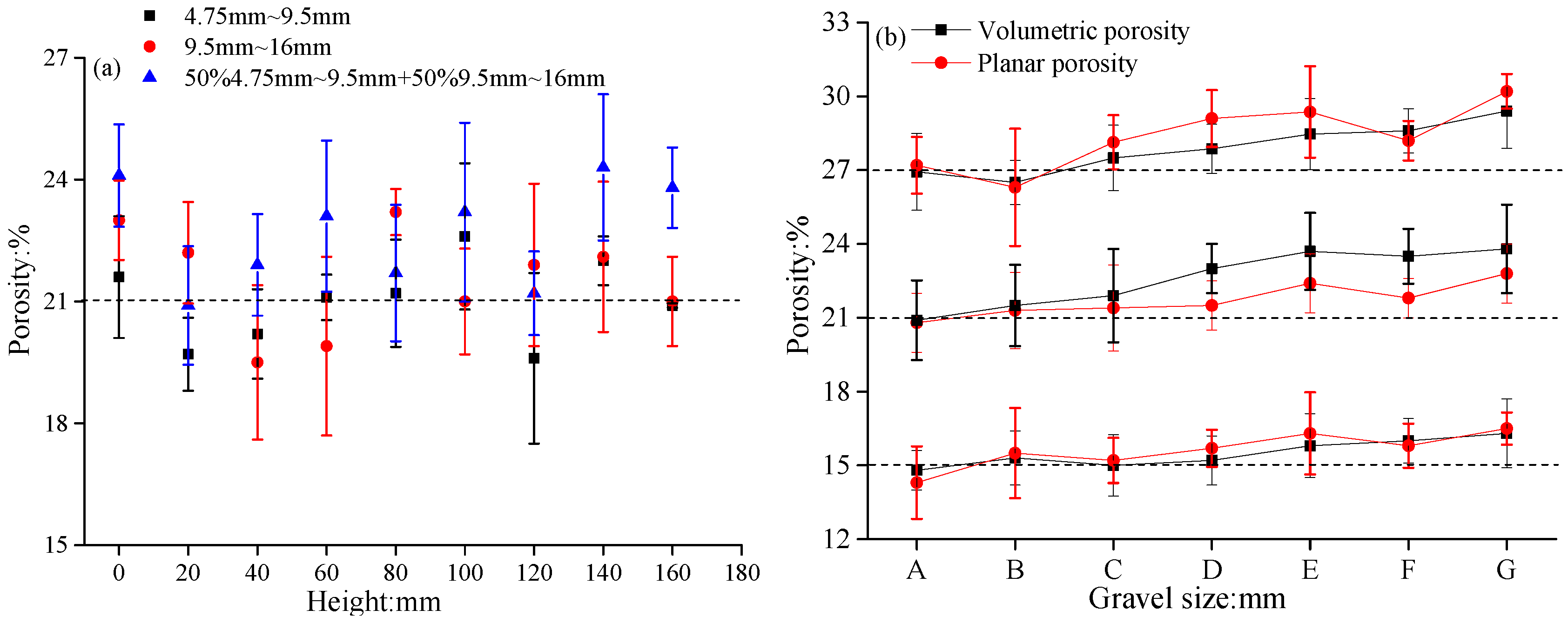
As shown by the results given in Figure 5a, three different sizes of the aggregate were used to study the effect of the specimen surface at different locations on the planar porosity. Figure 5b shows the volumetric porosity and average planar porosity of pervious concrete with different aggregate sizes.
As shown in Figure 5a, the difference value between the planar porosity and design porosity was within ±3%, so the planar porosity of the pervious concrete had less fluctuation at each cross-section. This indicated that the quality of the specimen using both the vibration and compaction method was more satisfactory. It can be seen from Figure 5b that the volumetric porosity and planar porosity increased when the design porosity increased. The difference value between the volumetric porosity and planar porosity was within ±3%. Additionally, the volumetric porosity and planar porosity of concrete with single-size aggregates were closer to the designed porosity. The pervious concretes with blended aggregates had higher porosity than those with single sizes of aggregates. The porosity of the pervious concretes with 50% 9.5–16 mm and 50% 16–19 mm aggregate sizes was the largest. The reason for this may be that a loosening effect may have occurred when big aggregates were pushed by small aggregates [18], and this increased the porosity of the pervious concretes.
3.2.2. Pore Distribution of Pervious Concrete
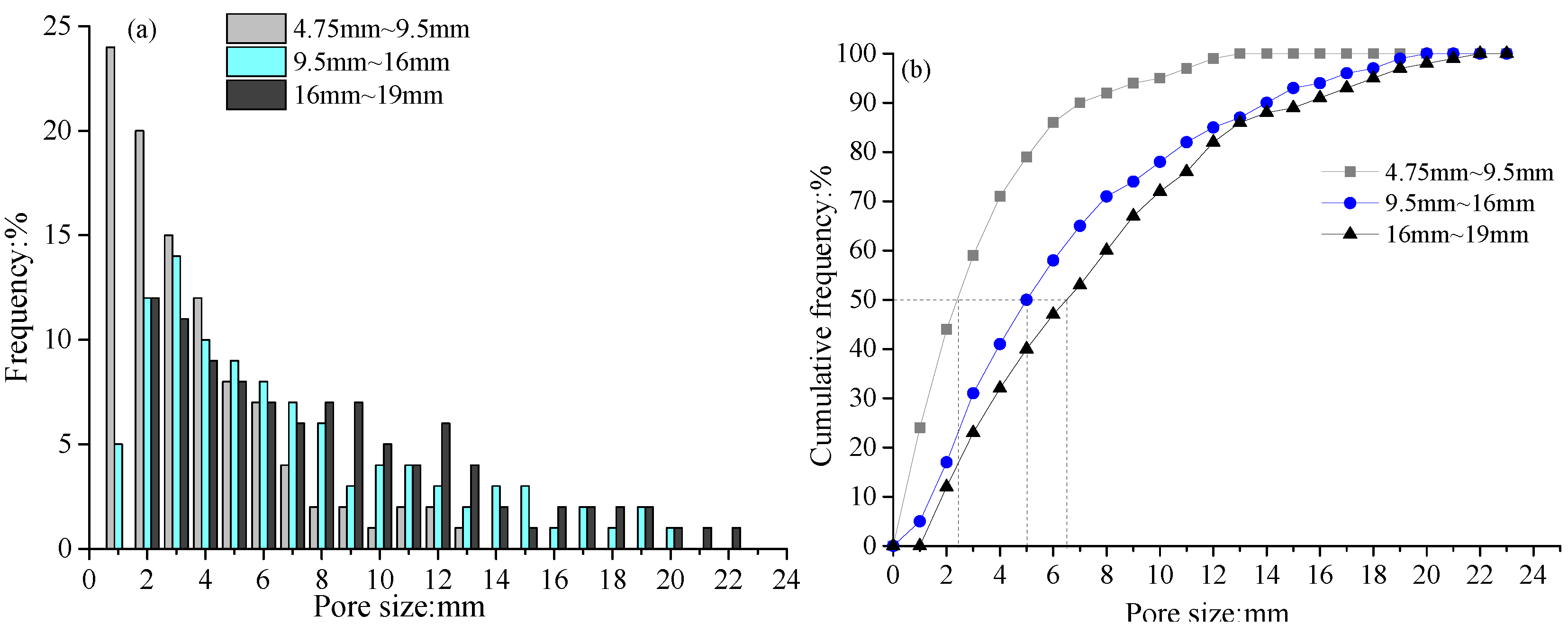
Figure 6 shows the effect of a single-size aggregate on the pore distribution of pervious concrete. Figure 6a shows the effect of a single-size aggregate on the pore size histogram. Figure 6b shows the effect of a single-size aggregate on the cumulative frequency distribution.
In Figure 6a, the pervious concrete with smaller aggregates had a higher proportion of smaller pores, whereas the pervious concrete with larger aggregates had a relatively large proportion of large pores. In Figure 6b, the pervious concrete with larger aggregates had a larger effective pore size (the pore size corresponding to 50% of the cumulative frequency distribution [8]), and its cumulative frequency curve increased more slowly. For example, when the aggregate size of concrete was 4.75–9.5 mm, the pore sizes of pervious concrete were mainly concentrated within 7 mm; 71% of the pores were smaller than 5 mm and the effective pore size was about 2.4 mm. When the aggregate size of concrete was 9.5–16 mm, the pore sizes of pervious concrete were mainly concentrated within 10 mm and the effective pore size was about 5 mm. However, 40% of the pores in the specimen with 9.5–16 mm aggregates were smaller than 5 mm, 28% of the pores were larger than 10 mm, and the effective pore size was about 6.5 mm. This was because the smaller aggregate resulted in a larger surface area and a more regular shape of the aggregate. Therefore, as the number of contact points between aggregates increased, the internal pore size decreased and the pore number increased.
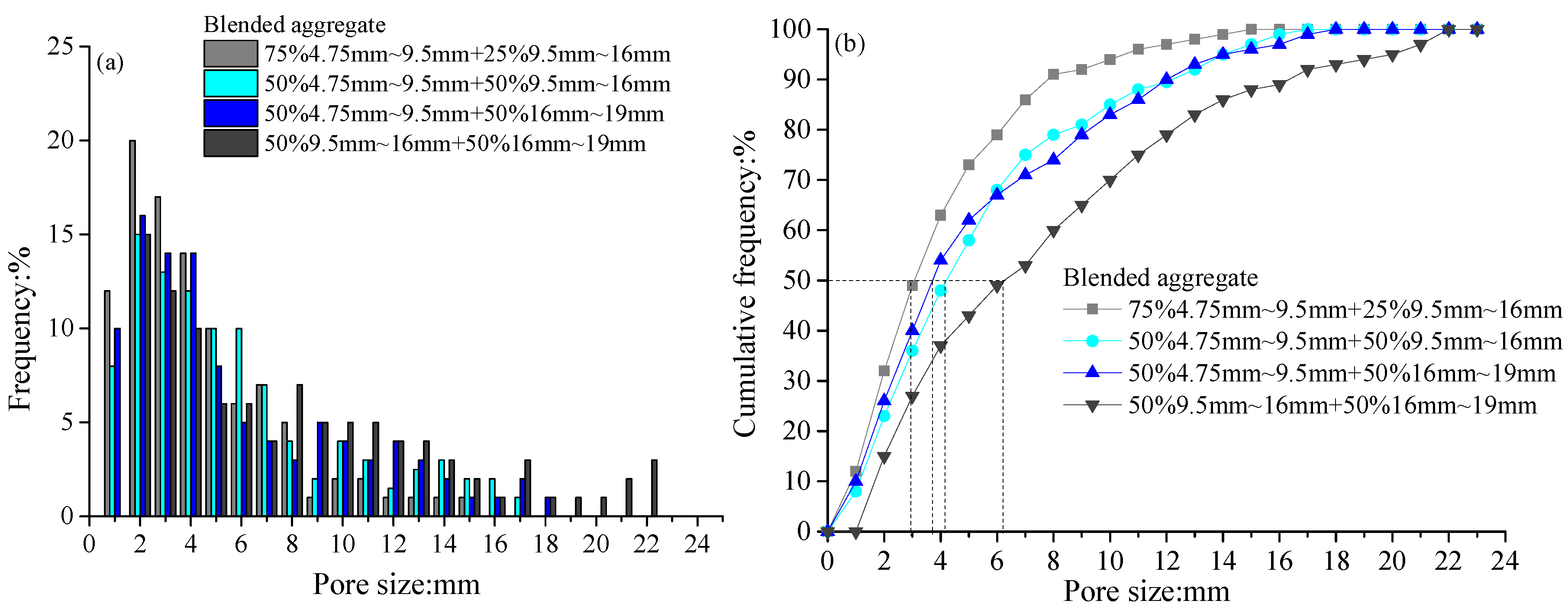
Figure 7 shows the effect of a blended aggregate on the pore distribution of pervious concrete. Figure 7a shows the effect of a blended aggregate on the pore size histogram. Figure 7b shows the effect of a blended aggregate on the cumulative frequency distribution.
The pore size distribution of pervious concrete with the blended aggregate size was close to that of concrete with the single-size aggregate. The addition of smaller aggregates in pervious concrete could improve the internal pore size distribution. With the increase of smaller aggregates in concrete, the proportion of larger pores decreased; at the same time, the effective pore size also decreased.
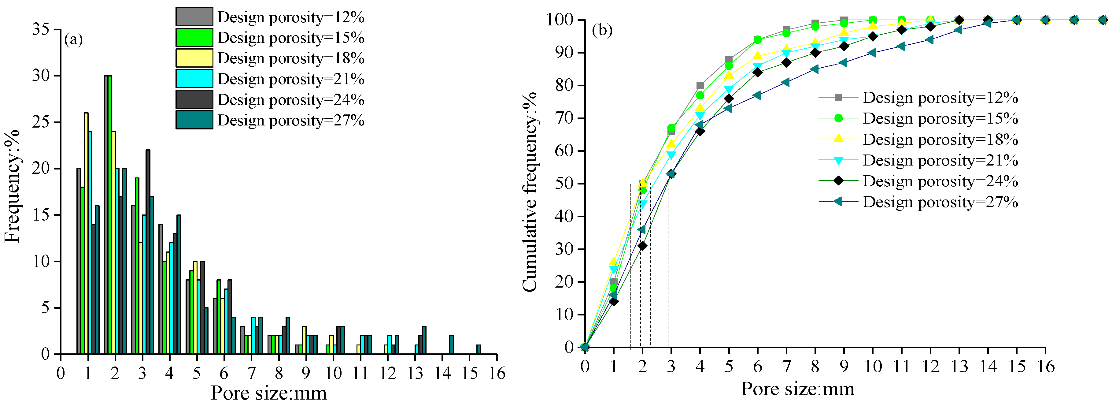
Figure 8 shows the effect of the design porosity on the pore distribution of pervious concrete. Figure 8a shows the effect of the design porosity on the pore size histogram. Figure 8b shows the effect of the design porosity on the cumulative frequency distribution.
In Figure 8b, the difference between all of the cumulative frequencies of pores was relatively low for different design porosities. The effective pore sizes were within 2–3 mm. In Figure 8a, there was only slight increase of large pores in the concrete with the larger design porosity. This might be attributed to the fact that the pervious concrete with a larger design porosity only resulted in a larger number of open and connected pores, but had little effect on the pore size of the concrete.
3.3. Permeability of Pervious Concrete
3.3.1. Accurate Determination of Permeability Coefficient
As shown by the results given in Figure 9, different design porosities and different aggregate sizes were used to study the effect of hydraulic gradients on the permeability coefficient, and the standard deviations of the permeability coefficient under three hydraulic gradients were calculated.
It was obvious that the standard deviation values of pervious concrete with different mixture ratios were no more than 0.03, and the variation of the standard deviation values was not regular. This reflected that the dispersion degree of the permeability coefficients under different hydraulic gradients was very small. The use of a visual permeameter and the sealed sidewall method with Vaseline and transparent wrapping film could effectively solve the problem of the permeability coefficient changing, as the hydraulic gradient changed due to side wall leakage.
Figure 10 shows the permeability coefficient of pervious concrete measured by the new method and traditional method (no blocking on the sidewall of the specimen). Figure 10a shows the permeability coefficient of pervious concrete with different design porosities. Figure 10b shows the permeability coefficient of pervious concrete with different aggregate sizes.
In Figure 10, the permeability coefficient tested by the traditional method was larger than that tested by the new method. Moreover, the larger design porosity and aggregate size resulted in a larger difference value of the permeability coefficient measured by the two methods. For example, in Figure 10a, the difference value of the permeability coefficient in pervious concrete with 12% design porosity was 0.35 mm/s, whereas the difference value increased to 2.8 mm/s for pervious concrete with 27% design porosity. In Figure 10b, the difference value of the permeability coefficient in pervious concrete with 4.75–9.5 mm aggregate size was 1.52 mm/s, whereas the difference value increased to 2.4 mm/s for pervious concrete with 16–19 mm aggregate size. This was because the larger design porosity and aggregate size resulted in a larger pore size and greater porosity of the sidewall surfaces. Thus, the leakage and permeability coefficient of pervious concrete increased in the traditional method.
3.3.2. Influential Factors of the Permeability Coefficient
As be seen from Figure 10a, the permeability coefficient increased as the design porosity increased. In particular, when the porosity was greater than 15%, a small change of porosity significantly changed the permeability coefficient. This was because the pervious concrete with a larger design porosity resulted in a larger measured porosity. When the measured porosity reached a critical value, the resistance of the internal structure of the concrete to water was greatly reduced, so the permeability coefficient increased rapidly. Figure 11a shows the relationship between the permeability coefficient and volumetric porosity of pervious concrete. It was found that the relationship between the permeability coefficient and volumetric porosity was right for a quadratic function, and the correlation coefficient was 0.97.
As can be observed in Figure 10b, the effect of the aggregate size on the permeability coefficient was significant. The permeability coefficient increased with the increase of single-size aggregates, and the permeable coefficient of the pervious concrete with the blended aggregate was slightly lower than that of concrete with the single-size aggregate. As shown in Figure 5b, there was little difference in the porosity variation of pervious concrete with different mix ratios. Therefore, the permeability coefficient was not sensitive to the porosity. The reason may be related to the internal pore sizes of pervious concrete; the larger aggregate size in the pervious concrete result in a larger internal pore size. Figure 11b shows the relationship between the effective pore size and the permeability coefficient. It was found that the relationship between the permeability coefficient and the effective pore size approximately obey the polynomial function, and the correlation coefficient was 0.93.
3.4. Strength of Pervious Concrete
As shown in Figure 12, two different aggregate sizes and three different design porosities were used in the pervious concrete samples. The compressive strength and flexural strength of the pervious concrete were measured.
In Figure 12, it was obvious that the strength of the pervious concrete increased with the decrease of the design porosity. It was also found that the strength of the pervious concrete with 4.75–9.5 mm aggregate size was larger than that with 9.5–16 mm aggregate size. For the pervious concrete with 4.75–9.5 mm aggregate sizes, the compressive and flexural strengths of the concrete with 15% design porosity were about 27.2 MPa and 4.1 MPa, respectively. Meanwhile, they were about 23.5 MPa and 3.3 MPa for the pervious concrete with 21% design porosity, respectively. For the pervious concrete with 9.5–16 mm aggregate sizes, they were about 19 MPa and 2.4 MPa for pervious concrete with 21% design porosity, respectively. At the same time, the strengths of the pervious concrete were satisfactory at 0.26–0.30 W/C ratios. For example, the compressive strengths of pervious concretes with 4.75–9.5 mm aggregate sizes were about 25.2–27.2 MPa, and the related flexural strengths were about 3.7–4.1 MPa. The strength of pervious concrete gradually increased with the increase of the curing time. It could be deduced that the strength was mainly dependent on the bonding strength, as well as the number of bonding points and bonding areas between cementitious materials and aggregates. The number of bonding points, contact areas, and effective bonding points increased with the decrease of design porosity and aggregate size.
4. Conclusions
- The segregation index of pervious concrete increased with the increase of SP and the W/C ratio, and the decrease of SF. The use of SP could significantly increase the flow value, while the use of SF signally reduced the flow value. The flow values of pastes and the segregation index for pervious concretes were obtained and found to be very suitable when the W/C of 0.26–0.30, 0.5% SP, and 5% SF were used.
- In the paper, volume porosity, planar porosity, and pore sizes were obtained by the water displacement method and image processing technology. It was found that the planar porosity of pervious concrete was close to the volumetric porosity. There was little difference between the measured porosity (volumetric porosity and planar porosity) and the design porosity when a single-size aggregate was used. However, the difference was large when a blended aggregate was used. This may be due to the possible loosening effect of the blended aggregates. The aggregate size was the main influencing factor of the pore distribution of the pervious concrete, and the effective pore size increased with the increase of the aggregate size. The design porosity had little effect on the pore distribution. The dosage of cementitious material decreased when the design porosity increased; correspondingly, the number of open and connected pores increased and the connections became difficult.
- Based on Darcy’s law, the permeameter and the sealed sidewall method can effectively solve the problem of sidewall leakage and the permeability coefficient can be accurately determined. The standard deviation of the permeability coefficient was less than 0.03 under different hydraulic gradients. The permeability coefficient of the pervious concrete was determined by the porosity and aggregate size jointly, and the permeability coefficient increased with increase of the aggregate size and design porosity. It was found that the relationships between the permeability coefficient and the volumetric porosity (or effective pore size d50) approximately obey the polynomial function.
- In the pervious concrete material system, the use of SF and SP improved the performance of pervious concrete, but the dosage of SF and SP should not be excessive. The strength of the concrete significantly increased with the increase of cementitious material and the decrease of aggregate size. When 15% design porosity and 4.75–9.5 mm aggregate size were used in concrete, the 28-day compressive strength was 27.2 MPa and the 28-day flexural strength was 4.1 MPa. Based on the performance of pervious concretes, the W/C of 0.26–0.30; 0.5% SP content; 5% SF content; 15–21% design porosity; and aggregate sizes of 4.75–9.5 mm and 9.5–16 mm are suggested.
Author Contributions
R.L., H.L. and F.S. conceived of and designed the study. H.L., F.S., and H.Y. performed the experiments. R.L., F.S. and Q.Z. developed the permeameter. R.L., H.L., F.S., H.Y., Q.Z., S.S. and Z.Z. wrote and modified the paper.
Funding
This research was funded by the General Program of the National Natural Science Foundation of China, grand number is 51779133; National Key R&D Plan of China, grand number is 2016YFC0801604; and Joint Funds of National Natural Science Foundation of China, grand number is U1706223.
Conflicts of Interest
The authors declare no conflict of interest.
References
- Tennis, P.D.; Leming, M.L.; Akers, D.J. Pervious Concrete Pavements; EB302 Portland Cement Association: Skokie, IL, USA, 2004. [Google Scholar]
- Schaefer, V.R.; Wang, K.; Suleiman, M.T.; Kevern, J.T. Mix Design Development for Pervious Concrete in Cold Weather Climates, Final Report; National Concrete Pavement Technology Center, Iowa State University: Ames, IA, USA, 2006. [Google Scholar]
- Malhotra, V.M. No-fines concrete-its properties and applications. ACI Mater. J. 1976, 73, 628–644. [Google Scholar]
- Liang, L. Preparation, Porous Structure and Camouflage Performance of Porous Ecological Concrete; Nanjing University of Aeronautics and Astronautics: Nanjing, China, 2010. [Google Scholar]
- Kevern, J.T. Advancement of Pervious Concrete Durability. Ph.D. Thesis, Iowa State University, Ames, IA, USA, 2008. [Google Scholar]
- Kevern, J.T. Mix Design Determination for Freeze–Thaw Resistant Portland Cement Pervious Concrete. Master’s Thesis, Iowa State University, Ames, IA, USA, 2006. [Google Scholar]
- Hu, J.; Stroeven, P. Application of image analysis to assessing critical pore size for permeability prediction of cement paste. Image Anal. Stereol. 2003, 22, 97–103. [Google Scholar] [CrossRef]
- Deo, O.; Neithalath, N. Compressive response of pervious concrete proportioned for desired porosities. Constr. Build. Mater. 2011, 25, 4181–4189. [Google Scholar] [CrossRef]
- Montes, F.; Valavala, S.; Haselbach, L. A new test method for porosity measurements of Portland cement pervious concrete. J. ASTM Int. 2005, 2, 73–82. [Google Scholar]
- Liu, R.; Li, B.; Jiang, Y. A fractal model based on a new governing equation of fluid flow in fractures for characterizing hydraulic properties of rock fracture networks. Comput. Geotech. 2016, 75, 57–68. [Google Scholar] [CrossRef]
- Liu, R.; Jiang, Y.; Li, B.; Yu, L. Estimating permeability of porous media based on modified Hagen–Poiseuille flow in tortuous capillaries with variable lengths. Microfluid. Nanofluid. 2016, 20, 120. [Google Scholar] [CrossRef]
- Kayhanian, M.; Anderson, D.; Harvey, J.T. Permeability measurement and scan imaging to assess clogging of pervious concrete pavements in parking lots. J. Environ. Manag. 2012, 95, 114–123. [Google Scholar] [CrossRef] [PubMed]
- Jiang, Z.; Sun, Z. Effects of Some Factors on Properties of Porous Pervious Concrete. J. Build. Mater. 2005, 8, 513–519. [Google Scholar]
- Yang, Z.F. Study on Material Design and Road Performances of Porous Concrete; Wuhan University of Technology: Wuhan, China, 2008. [Google Scholar]
- Martin, W.D., III; Kaye, N.B.; Putman, J.B. Impact of vertical porosity distribution on the permeability of pervious concrete. Constr. Build. Mater. 2014, 59, 78–84. [Google Scholar] [CrossRef]
- Yang, J.; Jiang, G. Experimental study on properties of pervious concrete pavement materials. Cem. Concr. Res. 2003, 33, 381–386. [Google Scholar] [CrossRef]
- Huang, B.; Wu, H.; Shu, X.; Burdette, E.G. Laboratory evaluation of permeability and strength of polymer-modified pervious concrete. Constr. Build. Mater. 2010, 24, 818–823. [Google Scholar] [CrossRef]
- Tamai, M. Water permeability of hardened materials with continuous voids. Cem. Assoc. Jpn. Rev. 1990, 446–449. [Google Scholar]
- Mishima, N.; Tanigawa, Y.; Mori, H.; Kurokawa, Y.; Terada, K.; Hattori, T. Experimental study on rheological properties of dense suspension by shear box test. J. Struct. Constr. Eng. 2000, 65, 13–19. [Google Scholar] [CrossRef]
- Lian, C.; Zhuge, Y.; Beecham, S. The relationship between porosity and strength for porous concrete. Constr. Build. Mater. 2011, 25, 4294–4298. [Google Scholar] [CrossRef]
- Larrard, D.F. Concrete Mixture Proportioning: A Scientific Approach; E&FN Spon: London, UK, 1999; p. 421. [Google Scholar]
Figure 1.
The segregation test device of pervious concrete.

Figure 2.
The permeability test device of pervious concrete.

Figure 3.
Flow values of pastes with different W/C (water cement ratio). Two to three pastes were prepared for each mix design and the figure shows an average of these together with the standard deviation.
Figure 3.
Flow values of pastes with different W/C (water cement ratio). Two to three pastes were prepared for each mix design and the figure shows an average of these together with the standard deviation.

Figure 4.
Segregation index of pervious concretes. (Three concrete specimens were prepared for each mix design and the figure shows an average of these together with the standard deviation).
Figure 4.
Segregation index of pervious concretes. (Three concrete specimens were prepared for each mix design and the figure shows an average of these together with the standard deviation).

Figure 5.
Porosity of pervious concrete. (a) Planar porosity, the design porosity was 21%; (b) volumetric porosity and average planar porosity, the design porosity was 15%, 21%, and 27%. The figure shows an average value and standard deviation of three to five specimens.
Figure 5.
Porosity of pervious concrete. (a) Planar porosity, the design porosity was 21%; (b) volumetric porosity and average planar porosity, the design porosity was 15%, 21%, and 27%. The figure shows an average value and standard deviation of three to five specimens.

Figure 6.
Effect of a single-size aggregate on the pore distribution of pervious concrete. (a) Frequency distribution of pore sizes; (b) cumulative frequency distribution of pore sizes. The design porosity was 15%. The figure shows the average value of three to five specimens.
Figure 6.
Effect of a single-size aggregate on the pore distribution of pervious concrete. (a) Frequency distribution of pore sizes; (b) cumulative frequency distribution of pore sizes. The design porosity was 15%. The figure shows the average value of three to five specimens.

Figure 7.
Effect of a blended aggregate on the pore distribution of pervious concrete. (a) Frequency distribution of pore sizes; (b) cumulative frequency distribution of pore sizes. The design porosity was 15%. The figure shows the average value of three to five specimens.
Figure 7.
Effect of a blended aggregate on the pore distribution of pervious concrete. (a) Frequency distribution of pore sizes; (b) cumulative frequency distribution of pore sizes. The design porosity was 15%. The figure shows the average value of three to five specimens.

Figure 8.
Effect of the design porosity on the pore distribution of pervious concrete. (a) Frequency distribution of pore sizes; (b) cumulative frequency distribution of pore sizes. The aggregate size was 4.75–9.5 mm. The figure shows the average value of three to five specimens.
Figure 8.
Effect of the design porosity on the pore distribution of pervious concrete. (a) Frequency distribution of pore sizes; (b) cumulative frequency distribution of pore sizes. The aggregate size was 4.75–9.5 mm. The figure shows the average value of three to five specimens.

Figure 9.
Standard deviation of the permeability coefficient of pervious concrete with different hydraulic gradients. The figure shows the average standard deviation values of three specimens.
Figure 9.
Standard deviation of the permeability coefficient of pervious concrete with different hydraulic gradients. The figure shows the average standard deviation values of three specimens.

Figure 10.
The permeability coefficient of permeable concrete under different test methods. (a) The design porosity of permeable concrete with 4.75–9.5 mm aggregate sizes; (b) the aggregate size of permeable concrete with 21% design porosity. The figure shows the average value and standard deviation of three specimens.

Figure 11.
Permeability coefficient of pervious concrete. (a) The relationship between the permeability coefficient and volumetric porosity of pervious concrete with aggregate sizes of 4.75–9.5 mm; (b) the relationship between the permeability coefficient and effective pore size of pervious concrete with 21% design porosity.

Figure 12.
Effect of the design porosity on the strength of pervious concrete. (a) Compressive strength; (b) Flexural strength. The figure shows an average value and standard deviation of three specimens.
Figure 12.
Effect of the design porosity on the strength of pervious concrete. (a) Compressive strength; (b) Flexural strength. The figure shows an average value and standard deviation of three specimens.


Table 1.
Chemical composition of materials.
| Name | Chemical Composition: % | ||||||||||
|---|---|---|---|---|---|---|---|---|---|---|---|
| SiO2 | CaO | Al2O3 | Fe2O3 | MgO | K2O | Na2O | SO3 | TiO3 | LOI | Others | |
| Cement | 23.52 | 61.47 | 7.59 | 2.42 | 1.70 | 0.57 | 0.27 | 0.65 | 0.11 | 0.84 | 0.86 |
| Silica fume (SF) | 97.2 | 0.42 | 0.27 | 0.08 | 0.55 | 0.48 | 0.19 | 0.51 | - | - | 0.30 |
* Chemical compositions of cement and silica fume were tested in the laboratory.
Table 2.
Properties of Polycarboxylate Superplasticizer (SP).
| Solid Content: % Al2O3 | pH | Density: g/mL Na2O | Na2SO4: % TiO3 | Cl−: % Others | Water Reducing Rate: % |
|---|---|---|---|---|---|
| 30.25 0.42 0.27 | 5.01 | 1.095 | 0.67 - | 0.03 0.30 | 32.1 |
* Properties of NC-J came from the manufacturer.
Table 3.
Gravel sizes.
| A | B | C | D | E | F | G | |
|---|---|---|---|---|---|---|---|
| Gravel sizes: mm | 4.75–9.5 | 9.5–16 | 16–19 | 75% 4.75–9.5 25% 9.5–16 | 50% 4.75–9.5 50% 9.5–16 | 50% 4.75–9.5 50% 16–19 | 50% 9.5–16 50% 16–19 |
Table 4.
Mix proportions of pervious concrete.
| Aggregate Size mm | Design Porosity % | Aggregate kg/m3 | Cement kg/m3 | SF (silica fume) kg/m3 | Water kg/m3 | SP(polycarboxylate superplasticizer) kg/m3 |
|---|---|---|---|---|---|---|
| 4.75–9.5 | 12 | 1489.0 | 546.1 | 28.7 | 161.0 | 2.87 |
| 15 | 1489.0 | 496.3 | 26.1 | 146.3 | 2.61 | |
| 18 | 1489.0 | 446.5 | 23.5 | 131.6 | 2.35 | |
| 21 | 1489.0 | 396.7 | 20.9 | 116.9 | 2.08 | |
| 24 | 1489.0 | 346.9 | 18.3 | 102.2 | 1.82 | |
| 27 | 1489.0 | 297.1 | 15.6 | 87.6 | 1.56 | |
| 9.5–16 | 12 | 1518.0 | 527.8 | 27.8 | 155.6 | 2.78 |
| 15 | 1518.0 | 478.0 | 25.2 | 140.9 | 2.51 | |
| 18 | 1518.0 | 428.2 | 22.5 | 126.2 | 2.25 | |
| 21 | 1518.0 | 378.4 | 19.9 | 111.5 | 1.99 | |
| 24 | 1518.0 | 328.7 | 17.3 | 96.9 | 1.73 | |
| 27 | 1518.0 | 289.4 | 15.2 | 85.3 | 1.52 | |
| 16–19 | 12 | 1529.0 | 519.5 | 27.3 | 153.1 | 2.73 |
| 15 | 1529.0 | 469.7 | 24.7 | 138.4 | 2.47 | |
| 18 | 1529.0 | 419.9 | 22.1 | 123.8 | 2.21 | |
| 21 | 1529.0 | 370.1 | 19.5 | 109.1 | 1.95 | |
| 24 | 1529.0 | 320.4 | 16.9 | 94.4 | 1.69 | |
| 27 | 1529.0 | 270.6 | 14.2 | 79.7 | 1.42 |
© 2018 by the authors. Licensee MDPI, Basel, Switzerland. This article is an open access article distributed under the terms and conditions of the Creative Commons Attribution (CC BY) license (http://creativecommons.org/licenses/by/4.0/).
Share and Cite
MDPI and ACS Style
Liu, R.; Liu, H.; Sha, F.; Yang, H.; Zhang, Q.; Shi, S.; Zheng, Z. Investigation of the Porosity Distribution, Permeability, and Mechanical Performance of Pervious Concretes. Processes 2018, 6, 78. https://doi.org/10.3390/pr6070078
AMA Style
Liu R, Liu H, Sha F, Yang H, Zhang Q, Shi S, Zheng Z. Investigation of the Porosity Distribution, Permeability, and Mechanical Performance of Pervious Concretes. Processes. 2018; 6(7):78. https://doi.org/10.3390/pr6070078
Chicago/Turabian StyleLiu, Rentai, Haojie Liu, Fei Sha, Honglu Yang, Qingsong Zhang, Shaoshuai Shi, and Zhuo Zheng. 2018. "Investigation of the Porosity Distribution, Permeability, and Mechanical Performance of Pervious Concretes" Processes 6, no. 7: 78. https://doi.org/10.3390/pr6070078
Note that from the first issue of 2016, this journal uses article numbers instead of page numbers. See further details here.