Article

Two-Step Performance Optimization of CsPbBr3 Perovskite Nanocrystals for Wide Color Gamut Displays

1
National & Local United Engineer Laboratory of Flat Panel Display Technology, College of Physics and Information Engineering, Fuzhou University, Fuzhou 350108, China
2
Fujian Science & Technology Innovation Laboratory for Optoelectronic Information of China, Fuzhou 350108, China
*
Author to whom correspondence should be addressed.
Photonics 2023, 10(10), 1113; https://doi.org/10.3390/photonics10101113
Submission received: 31 August 2023 / Revised: 21 September 2023 / Accepted: 29 September 2023 / Published: 2 October 2023
(This article belongs to the Special Issue Liquid Crystals in Photonics)

Abstract

:
Owing to their composition-tunable and narrow emissions and high photoluminescence quantum yield (PLQY), inorganic halide perovskite quantum dots (IPQDs) are a promising option for wide color gamut displays. However, their practical applications have been limited by their lattice structure instability and surface defect states. Herein, CsPbBr3:KBF4@SiO2 with improved stability and optical properties is successfully synthesized with a two-step optimization of fluorine (F) anion doping and SiO2 in situ coating. Compared with bromide (Br), higher electronegativity and a smaller radius of F lead to stronger binding energy with Pb2+. Also, F anions can occupy surface Br vacancies. Then, benefiting from the acidic environment provided by BF4 hydrolysis, tetraethyl orthosilicate (TEOS) can be more easily hydrolyzed on the CsPbBr3:KBF4 surface to generate SiO2 coating, thus further passivating lattice defects and improving environmental stability. Importantly, the PLQY of CsPbBr3:KBF4@SiO2 achieves 85%, and the stability has been greatly improved compared with pure CsPbBr3. Finally, CsPbBr3:KBF4@SiO2/PDMS, CsPbI3/PDMS, and CsPbCl3/PDMS composites with narrow emissions are applied to replace traditional phosphors as color converters for direct-view light-emitting diode (LED) displays or liquid crystal display (LCD) backlights. The color gamut reaches 118.22% under the NTSC standard. Concerning the display field, it suggests likely applications in the future.

1. Introduction

Sought after in the world of semiconductor nanomaterials are metal halide perovskites (MHPs) comprising an ABX3 structure [1,2,3,4]. For optoelectronic devices, inorganic perovskite quantum dots (IPQDs), among MHPs, are especially fitting due to their extraordinary features, including low excitonic binding energy, narrow emission spectra, and high photoluminescence quantum yields (PLQYs), among several others [5,6]. There has been much interest in these properties, leading to an expansion in the research regarding their applications, namely displays [7,8], solar cells [9,10], photodetectors [11,12], light-emitting diodes (LEDs) [13,14], sensors [15,16], and so forth.
However, perovskite nanocrystals (NCs) may undergo lattice decomposition when in contact with oxygen, moisture, or high temperature due to their lattice structure instability and surface defect states [17,18]. Therefore, strategies to improve stability are pivotal to their commercial application [19,20,21]. Many attempts have been presented to confront these issues [22,23]. Some widely used strategies are surface modification [24], coating [25], or doping [26], etc. According to Li et al., compared with the inner nanocrystal core, fluorine (F)-rich surfaces have a larger energy gap, resulting from post-synthesis treatment with F anions. This achieves efficient charge injection, enhanced thermal stability, and suppressed carrier trapping [10]. With an outmost PS shell, an intermediate layer of the SiO2 shell, and an inter-core of CsPbBr3, organic–inorganic double-shell CsPbBr3@SiO2@polystyrene (PS) NCs were synthesized through a practical approach, as reported by Hong et al. Under 85% relative humidity (RH) in 85 °C or irradiation with a UV lamp for a month, over 90% of the initial PL intensity of the CsPbBr3@SiO2@PS NCs was preserved [27].
In this work, we successfully synthesized CsPbBr3:KBF4@SiO2 NCs with improved performance and stability with a two-step optimization of F anion doping and SiO2 in situ coating. The presence of BF4 provides an environment that is more conducive to the hydrolysis of silica monomers (tetraethyl orthosilicate, TEOS). The results show that the synthesized CsPbBr3:KBF4@SiO2 exhibit an enhanced PLQY of 85% and environmental stability. Beyond that, CsPbBr3:KBF4@SiO2/PDMS, CsPbI3/PDMS, and CsPbCl3/PDMS composites with narrow emissions can replace traditional phosphors as color converters. The three-primary-color (TPC) LEDs provide a wide color gamut of 118.22% under the NTSC standard. In the display field, this is anticipated to demonstrate great applications.

2. Experimental Section

Materials: The materials included cesium carbonate (99.9%, Sigma-Aldrich, St. Louis, MO, USA), oleic acid (90%, Sigma-Aldrich, St. Louis, MO, USA), octadecene (90%, Sigma-Aldrich, St. Louis, MO, USA), oleylamine (80%~90%, Aladdin, Seattle, WA, USA), lead (II) bromide (99%, Aladdin, Seattle, WA, USA), polydimethylsiloxane (Mw = 25,000, Dowcorning, Midland, MI, USA), toluene (99%, Sigma-Aldrich, St. Louis, MO, USA), tetraethyl orthosilicate (99%, Aladdin, Seattle, WA, USA), and potassium tetrafluoroborate (99%, Aladdin, Seattle, WA, USA).
Synthesis of CsPbBr3 nanocrystals: First, CsCO3 (0.203 g), ODE (10 mL), and OA (1 mL) were mixed extensively into a 50 mL three-necked flask under nitrogen. Then, the mixture was treated by vigorous magnetic stirring for 1 h at a temperature of 120 °C. Then, PbBr2 (0.0745 g) and ODE (12 mL) were added into a dry 50 mL three-necked flask, and argon was passed into the flask at 80 °C for 1 h. Then, the temperature was raised to 120 °C. Oleic acid (0.5 mL) and oleamine (1.5 mL) were added at a ratio of 0.5:1.5. When the PbBr2 was completely dissolved, the temperature was raised to 180 °C, and 1 mL cesium oleate was quickly added. After reaction for 1 min, the liquid was cooled in a water bath. After cooling to room temperature, a three-neck flask was taken out, and the reaction mixture was poured into a dry centrifuge tube. And the mixed solution was centrifuged several times at a speed of 8500 for 8 min. The supernatant after centrifugation was re-dispersed in toluene and stored for later use.
Synthesis of CsPbBr3:KBF4 nanocrystals: The synthesis procedure is the same as the above synthesis method, except that 0.0012 g KBF4 is added to the precursor solution.
Synthesis of CsPbBr3:KBF4@SiO2: 0.13 mL silica precursor (TEOS) was added to the prepared CsPbBr3:KBF4 nanocrystal solution and stirred at room temperature with the lid open for 12 h.
Synthesis of CsPbBr3:KBF4@SiO2/PDMS: The prepared CsPbBr3:KBF4@SiO2 were mixed with PDMS copolymer solution under stirring for 30 min to obtain a uniform viscous solution. The resulting solution was then poured onto a temporary Teflon mold and placed in a vacuum drying oven to evaporate the solvent until a yellow composite gel was formed. Finally, the composite material was peeled off for further use.
Characterization: The TEM observations were performed with a FEI TECNAI G2 F20 (FEI Corporation, Hillsboro, OR, USA). The ultraviolet–visible (UV-vis) absorption and photoluminescence (PL) spectra were tested with F-4600 (Hitachi, Tokyo, Japan) and UV-3600 (Shimadzu, Japan), respectively. The X-ray diffraction (XRD) patterns were collected by using DY1602/Empyrean (Panaco, Dutch, Beersel, Belgium). The Fourier transform infrared (FTIR) patterns were collected by using Nicolet iS50 (Thermo Fisher Nicolet, Waltham, MA, USA). X-ray photoelectron spectroscopy (XPS) patterns were collected by using Escalab 250 (VG, Seattle, WA, USA). Time-resolved photoluminescence (TRPL) readings were collected with FLS980 (Edinburgh Corporation, Scotland, UK).

3. Results and Discussions

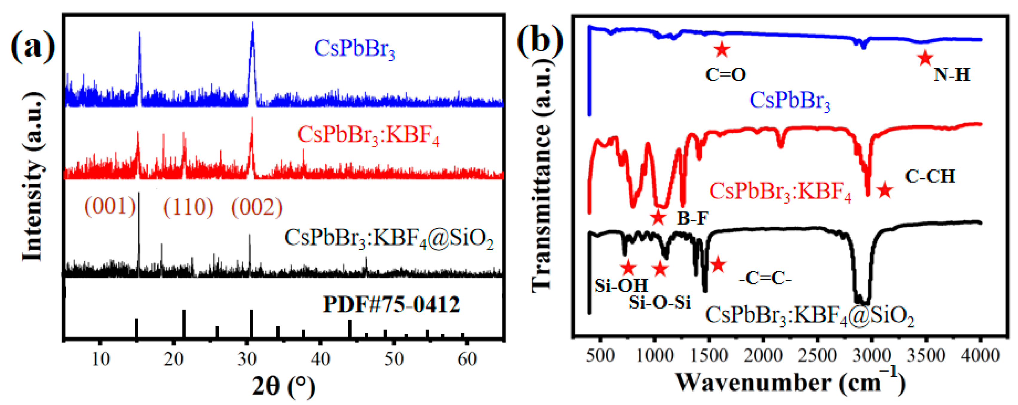
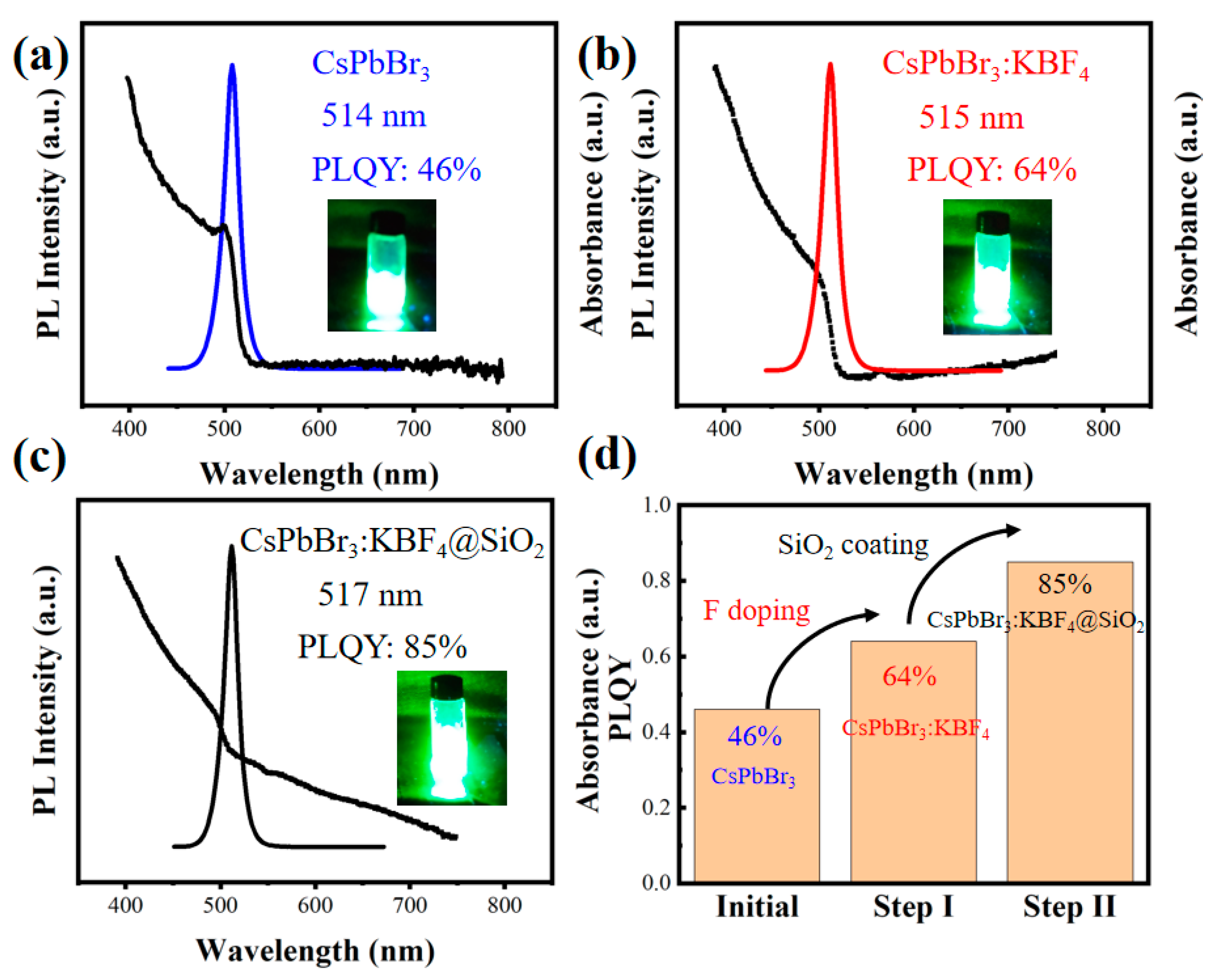
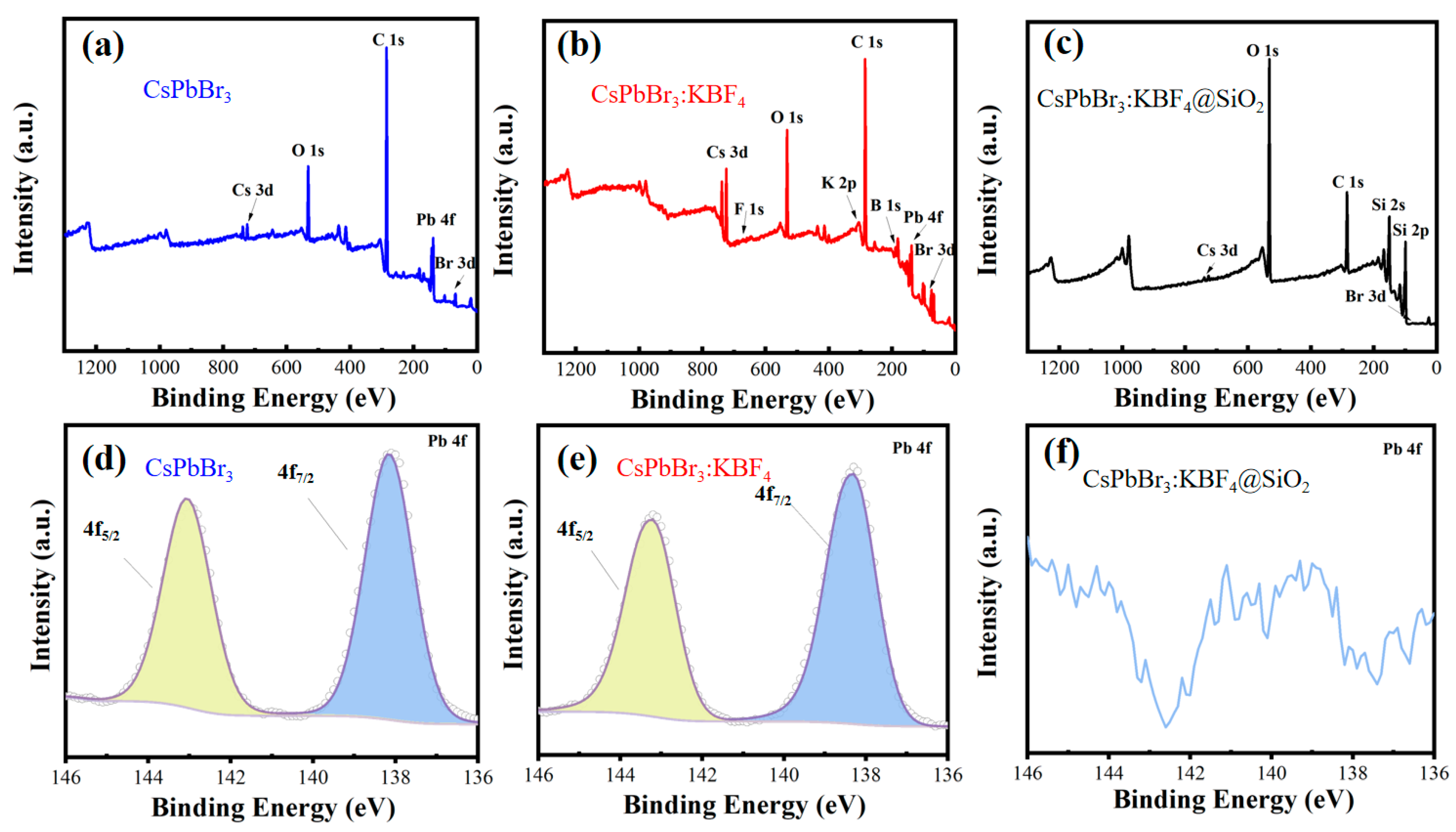
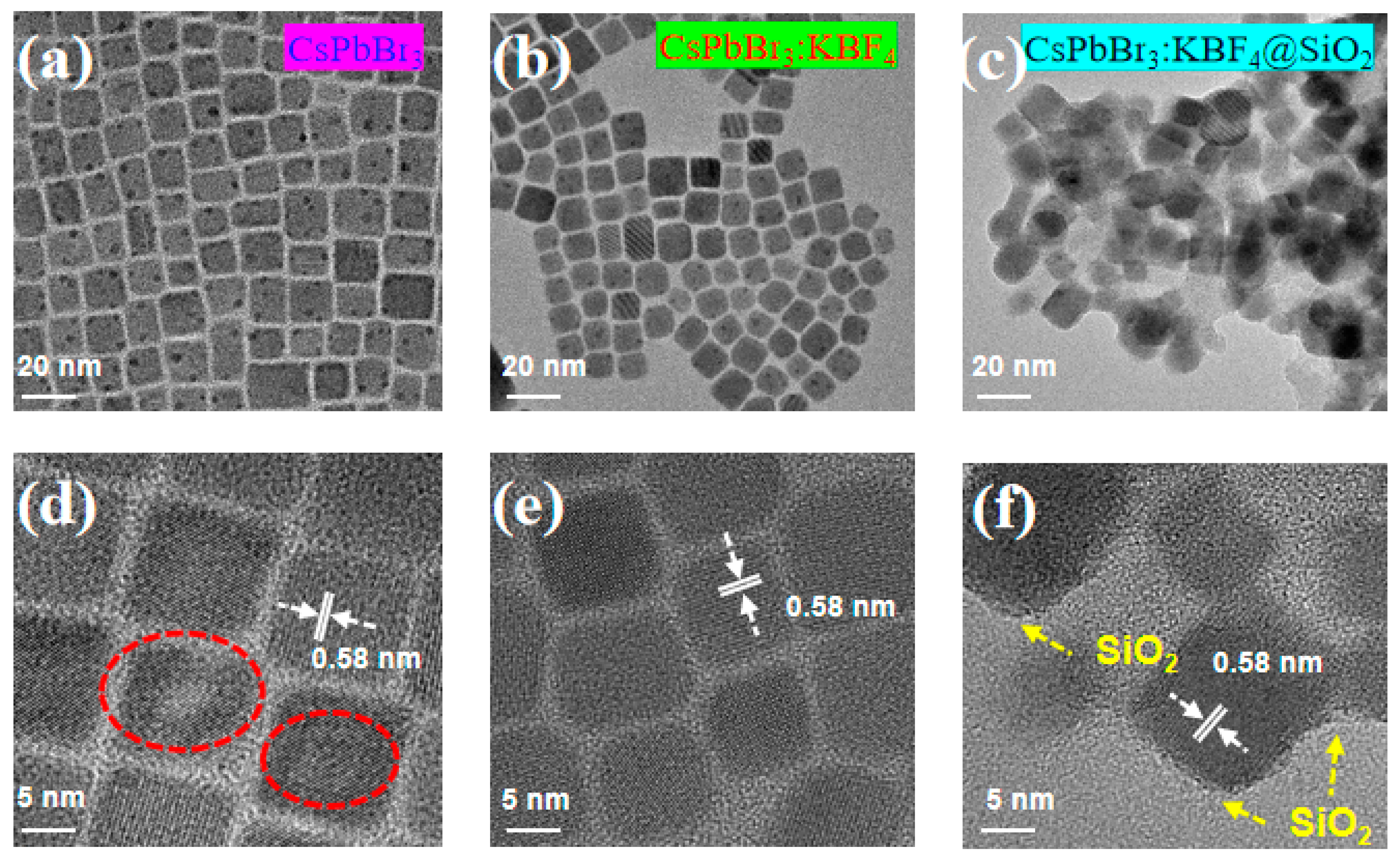
3.1. Preparation and Characterization

Through the traditional hot injection method, we prepared the CsPbBr3 nanocrystals. Prior to allowing them to grow after cooling, the QDs were nucleated at a high temperature as a core principle [28]. Specifically, this can be summarized as follows: the pre-prepared Cs-oleate precursor solution was injected into the ligand solution at a high temperature, and then nucleation was achieved in a very short time. The preparation process of CsPbBr3: KBF4@SiO2 is shown in the picture in Figure 1 below. F-doped IPQDs were firstly synthesized in Step I and Step II, and then TEOS was added for in situ coating (shown in Step III). The difference between CsPbBr3 and CsPbBr3:KBF4 in the synthesis step is that KBF4 is added in the preparation of the precursor of Cs-oleate precursor, where the ratio of bromide (Br) to F is around 8%. It has been suggested in the literature that further overuse of F precursors leads to the degradation of the perovskite structure [10]. Then, the precursor solution was quickly injected into the PbBr2 solution at a high temperature, and the CsPbBr3:KBF4 solution was obtained after cooling. In order to further stabilize the lattice and passivate the defects, we added monomer TEOS to CsPbBr3:KBF4 to obtain CsPbBr3:KBF4@SiO2. It is worth mentioning that the modification of KBF4 on the surface of CsPbBr3 is more conducive to the hydrolysis of TEOS to SiO2. The reason for this is that BF4 shows an acidic environment under the action of water molecules, and TEOS is more easily hydrolyzed to SiO2 under acidic conditions [29]. Provided by acid, the protons will merge with water molecules to produce hydrated protons. Then, accordingly, under acidic conditions, the tangs of the alkoxy group will first encounter this group’s electrophilic attack. It must be noted that, in the TEOS molecules, this alkoxy group has relatively high electron cloud density. Facilitating the breaking of Si-OR bonds in TEOS molecules is the protonation of the whole alkoxy group due to the abovementioned process. With a positive charge, H+ is fundamentally a proton. The Lewis acid–base theory postulates the tendency of hydrogen ions to accept pairs of electrons. In this case, H+ can combine with water molecules with a pair of lone electrons to form a stable hydrogen bond and generate hydrated protons, also known as antimony ions, which are conducive to attacking alkoxy groups.
As shown in Figure 2, the morphologies and structures of CsPbBr3, CsPbBr3:KBF4, and CsPbBr3:KBF4@SiO2 were characterized by TEM and high-resolution TEM (HRTEM), respectively. The synthesized CsPbBr3 and CsPbBr3:KBF4 show an approximately cubic shape with a lattice spacing of 0.58 nm, corresponding to the (100) plane of cubic CsPbBr3. The CsPbBr3 core of CsPbBr3:KBF4@SiO2 also has a lattice spacing of 0.58 nm, indicating that the CsPbBr3 did not undergo lattice shrinkage during the coating process. The stability differences between CsPbBr3, CsPbBr3:KBF4, and CsPbBr3:KBF4@SiO2 can also be seen from the behavior of the three samples under an electron microscope. Firstly, the small black dots in Figure 3a are heavy metal elements (Pb) damaged by the electron beam, while the black dots in Figure 3b,c gradually decrease, indicating that the samples are becoming more and more stable to the electron beam. Secondly, by comparing their HRTEM images, we can find that part of the lattice of the CsPbBr3 will be broken down under the bombardment of high-energy electron beams (red dashed coil), resulting in lattice loss. The lattice fringes of CsPbBr3:KBF4 and CsPbBr3:KBF4@SiO2 are clearly visible under high-power lenses and are not easily decomposed by electron beams. From the side, we can judge the difference in stability of the three materials.
The compositional distributions of the NCs were further investigated by energy-dispersive X-ray spectroscopy (EDS). The energy spectrum (Figure S1) and elemental mapping images (Figure 3) show that Cs, Pb, Br, B, F, K, Si, and O elements were all detected, thus proving the formation of CsPbBr3:KBF4 and CsPbBr3:KBF4@SiO2. Among them, the element distribution profile of the boron (B) element is not sufficiently obvious; this may be because the relative mass of the B element is too light, and the detection accuracy is not high [10]. However, the B element exists in the form of BF4, and the element distribution of F is clear, which can explain the doping of KBF4 well. The same phenomenon has been observed for the Si element, possibly because of the substrate used for the test. The reason why the element mapping figures have a certain blurriness may be described as follows: (1) The organic ligands on the surface of NCs will carbonize under electron beam bombardment for a long time, which will cause blurred vision. (2) The perovskite material itself is not stable enough under the bombardment of the electron beam for a long time, so the accuracy of the test is reduced.
XRD was used to monitor the structural evolution of the NCs during the synthesis process (Figure 4a). The CsPbBr3 NCs show main diffraction peaks at 15.2°, 21.5°, and 30.7°, which correspond to the diffraction of the cubic CsPbBr3 (100), (110), and (200) planes (PDF#75-0412), respectively. In CsPbBr3:KBF4 and CsPbBr3:KBF4@SiO2, it is possible to observe each of these diffraction peaks, implying that throughout the coating process no phase change transpires, and good phase stability and crystallinity are exhibited by the sharp peaks of CsPbBr3:KBF4@SiO2 composites [30]. In addition to this, potentially associated with the high crystallinity of CsPbBr3 NCs are the unobtrusive characteristic peaks of a limited quantity of amorphous silica. The half-height and width of the diffraction peaks gradually narrow, indicating high crystallinity and good crystal quality. These results verify the significance of the F doping and coating strategy from the side [31].
The FTIR spectra of CsPbBr3, CsPbBr3:KBF4, and CsPbBr3:KBF4@SiO2 are shown in Figure 4b. Each red star represents the functional group corresponding to the wavenumber at that position. The N-H stretching vibration at 3420 cm−1 and the C=O stretching vibration at 1720 cm−1 should be attributed to the oleic acid and oleylamine surface ligands. The characteristic FTIR absorption band of B-F is in the range of 1000–1100 cm−1, which proves the successful doping of the F element. For CsPbBr3:KBF4@SiO2, Si-O-Si and Si-OH stretching vibrations can be observed at about 1050 cm−1 and 960 cm−1 [10]; the coating of SiO2 is also further proved.
Figure 5 shows the UV-vis absorption and PL spectra of the prepared CsPbBr3, CsPbBr3:KBF4, and CsPbBr3:KBF4@SiO2 dispersed in toluene solution. With 17.2 nm as the full width at half maxima (FHWM) and 514 nm as the peak wavelength, CsPbBr3 has a symmetric and unique PL spectral peak. Moreover, the PL spectral peak of CsPbBr3:KBF4 is located at 515 nm, and the FHWM is 16.1 nm. The PL spectral peak of CsPbBr3:KBF4@SiO2 is located at 517 nm, and the FHWM is 17.9 nm. The reason for the wavelength redshift and the FHWM widening before and after the SiO2 coating is the partial agglomeration of NCs [32]. The SiO2 is easy to agglomerate in the treatment process due to the large surface energy. The reason for the redshift of the emission spectrum compared with the absorption spectrum is that the excited molecules undergo vibration relaxation and internal conversion before the emission of fluorescence and lose part of their energy [33]. Here, it is worth mentioning that we believe that the phenomenon of the inclined rise of the absorption spectrum in Figure 5c may be attributed to the introduction of polymer impurities. Through numerous experimental tests, we found that if the NCs are not purified or there are other impurities in the surfaces of NCs, the baseline tilt will rise.
The PLQYs of the CsPbBr3, CsPbBr3:KBF4, and CsPbBr3:KBF4@SiO2 are 46%, 64%, and 85%, respectively. Figure 5d shows the comparative relationships between the PLQY of CsPbBr3, CsPbBr3:KBF4, and CsPbBr3:KBF4@SiO2. We can find that CsPbBr3:KBF4@SiO2 with an improved PLQY can be successfully prepared with the two-step (Step I and Step II) optimization of F anion doping and SiO2 in situ coating.

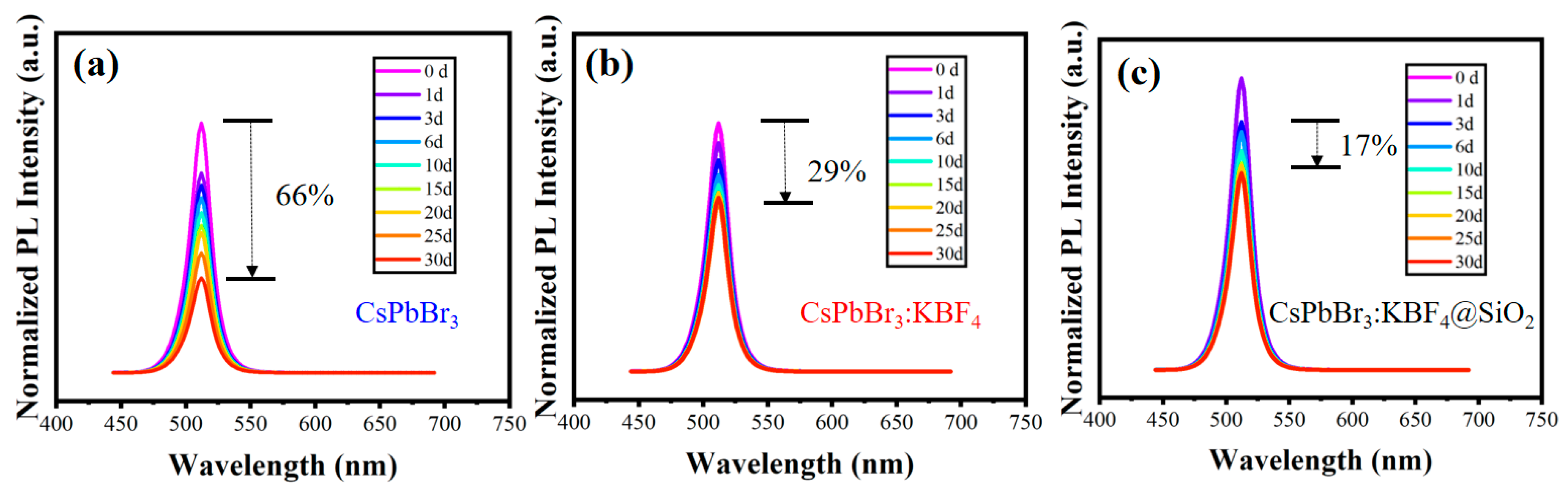
3.2. Performance and Stability Analysis

By comparing the PLQY of the CsPbBr3, CsPbBr3:KBF4, and CsPbBr3:KBF4@SiO2, it can be found that they have two steps of promotion. F doping provides the first step of optimization, and SiO2 coating provides the second step of promotion.
Figure 6 shows the XPS measurement of CsPbBr3, CsPbBr3:KBF4, and CsPbBr3:KBF4@SiO2 and the corresponding Pb4f high-resolution spectra. The full spectrum of the CsPbBr3:KBF4 shows Cs, Pb, Br, C, O, K, B, and F elements, verifying the doping of KBF4. CsPbBr3:KBF4@SiO2 shows Si, O, and C elements. The elements of Cs, Pb, and Br cannot be detected in the whole spectrum, and the content of the O element increases, indicating the in situ coating of SiO2. One of the standardized surface analysis techniques is known as XPS. While X-rays can go deep into the sample, only photoelectrons that come from a thin layer near the sample’s surface can escape. That may be the reason why Cs, Pb, and Br cannot be detected in CsPbBr3:KBF4@SiO2. The high-resolution XPS spectra of Pb4f for three samples are shown in Figure 6d–f. We used the Gaussian Lorentz mixing function to fit the Pb4f orbit by peaks, where the white circle points are the measured data and the solid lines are the fitted data. The Pb2+ 4f7/2 and Pb2+ 4f5/2 binding energies of CsPbBr3 and CsPbBr3:KBF4 decrease from 138.32 and 143.22 eV to 138.15 and 143.05 eV, respectively. The low energy shift indicates that the electron density is increasing. The BF4 group eliminates the possibility of exciton trapping the vacancies of the Br, which firmly binds to the exposed Pb2+ to form a stable bond, and the Pb2+ obtains electrons, so that the binding energy is shifted to the low energy, that is, its electron density is increased [34,35].
In order to further verify the passivation of defect states by F doping and SiO2 coating, the TRPL of CsPbBr3, CsPbBr3:KBF4, and CsPbBr3:KBF4@SiO2 were recorded. Figure 7 illustrates the findings, and Table 1 itemizes the obtained parameters. The biexponential equation offers a great fit to the PL decay curves. The decay times τ1 are 9.2, 8.6, and 7.9 ns, and τ2 are 36.8, 39.6, and 43.9 ns for CsPbBr3, CsPbBr3:KBF4, and CsPbBr3:KBF4@SiO2, respectively. In sequence, 18.2, 21.0, and 25.8 ns were the average decay times. Linked to the long-lasting radiation recombination process [36,37], the τ2 values post-F doping rose to 39.6 ns from 36.8 ns. Then, post-SiO2 coating, they increased to 43.9 ns from 39.6 ns. By contrast, τ1 displayed a different transformation, specifically during post-SiO2 in situ coating and post-F anion doping, where a significant suppression of the nonradiative recombinations occurred. It has been documented that a decrease in surface traps results in longer lifespans [1,14]. F anion doping and SiO2 in situ coating were optimized in two steps. Afterward, concerning the CsPbBr3 NCs, their surface defects were passivated, as indicated by the changes in τ1 and τ2.
As previously analyzed, the doping of F and the coating of SiO2 can not only form a strong combination with Pb2+ but also occupy the passivation defects of Br vacancies. This two-step performance optimization improves luminescence performance and also stabilizes the lattice to improve stability. We placed the three samples in the environment for 30 days and observed the environmental stability of the three samples. As shown in Figure 8, for CsPbBr3, the PL decays to 34% of its original value; for CsPbBr3:KBF4, the PL decays to 71% of the original; for CsPbBr3:KBF4@SiO2, PL decays to 83% of the original. It is worth mentioning that CsPbBr3:KBF4@SiO2 had a phenomenon of fluorescence enhancement at the initial stage, which is mainly due to the certain degree contact between the NCs and air. The surface defects on the surface of the NCs can be passivated by an oxidation reaction, so that the electrons can be re-filled in the conduction band, thus enhancing the fluorescence characteristics. This phenomenon is commonly known as photoactivation [38,39]. Due to steric hindrance of the organic ligand and the weak bond between the raw material compound in the process of perovskite synthesis, there are many defects and overhanging bonds on the surface of NCs. In addition, the magnetic agitation process during hydrolysis to generate SiO2, as well as the interaction between protic solvents, may also lead to the separation of some ligands from the surface of the NCs. When exposed to light, water, or oxygen, the surface of the nanomaterial is photooxidized, and some surface defects are passivated through an oxidation reaction, resulting in a certain degree of improvement in fluorescence efficiency. However, this phenomenon generally only exists in the contact of trace amounts of water and oxygen with NCs, which plays a positive role in perovskite materials. CsPbBr3 and CsPbBr3:KBF4 did not show a similar photoactivation phenomenon, which is mainly because NCs without SiO2 coating protection are exposed to more water and oxygen, destroying the core of the lattice and causing it to degrade. As time goes on, regardless of whether there is a SiO2 coating, the NCs will come into contact with more and more water and oxygen and will also show a decrease in fluorescence. This may be the reason why the fluorescence of CsPbBr3 and CsPbBr3:KBF4 continues to decline over time, while the fluorescence of CsPbBr3:KBF4@SiO2 first increases and then decreases.

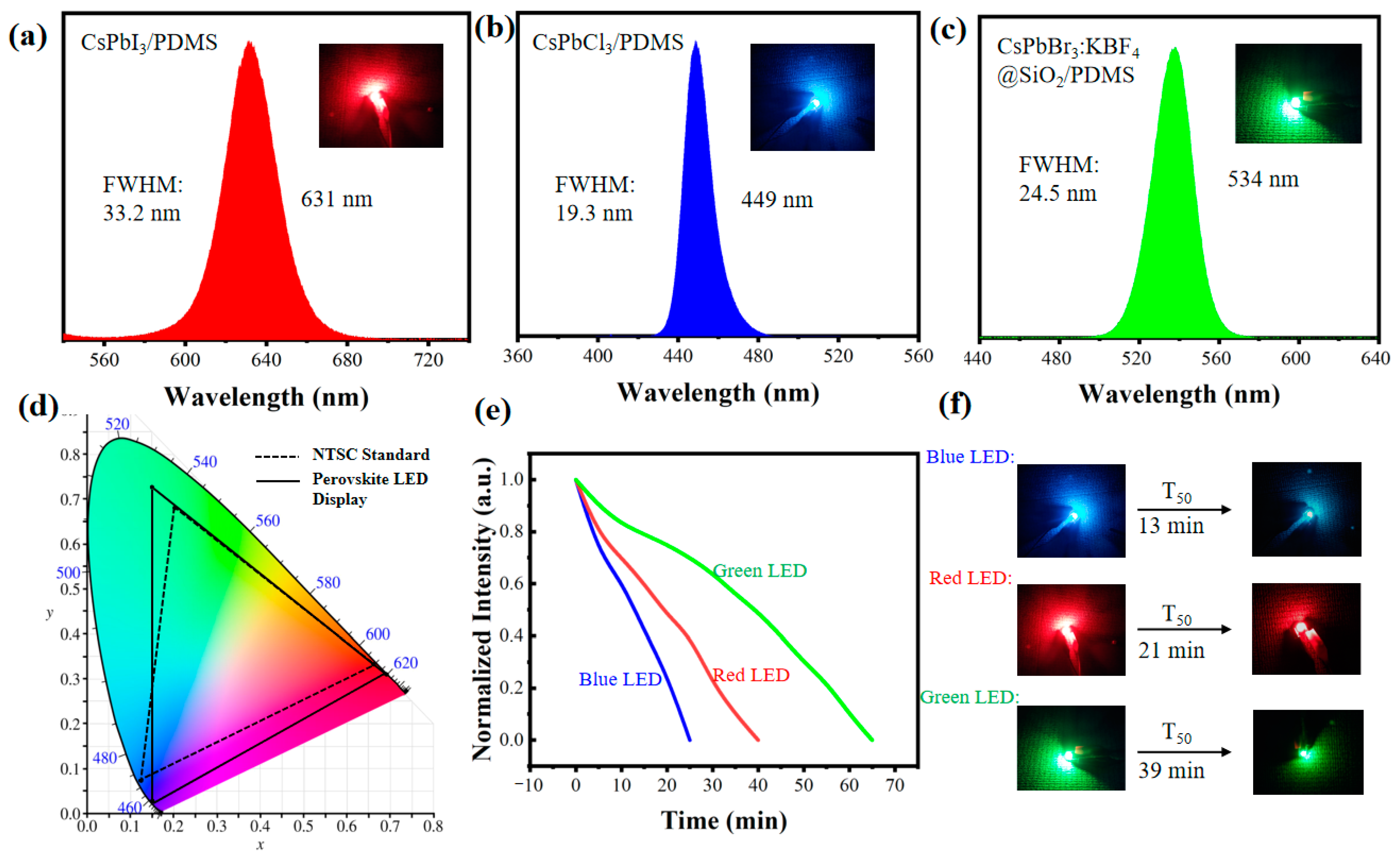
3.3. LED Application

In LCD backlights or direct-view LED displays, perovskite materials are viable alternatives for color conversion [40,41]. The difference is that the direct-view LED display is usually self-emissive, and the LCD requires an LED backlight. Furthermore, high-color-purity LED sources are essential. To address this, the three-primary-color-converted LED sources were prepared. CsPbBr3:KBF4@SiO2 was used as the green color conversion material. CsPbI3 and CsPbCl3 were obtained from our previous work as the red and blue color conversion materials. For this experiment, the color conversion layers were prepared for bare UV LEDs by mixing polydimethylsiloxane (PDMS) and TPC PQDs [42]. The corresponding pictures when lit up and the spectra of the TPC LEDs are depicted in Figure 9a–c. Using the 1931 chromaticity diagram of the Commission Internationale del’Eclairage (CIE), the prepared LEDs and their chromaticity coordinates are shown in Figure 9d. Concerning the color gamut of the TPC LED sources, the National Television Standards Committee (NTSC) standard was utilized for a more exhaustive assessment. The combination of the long dashed line and the solid line forming triangles stands for the 100% NTSC standard and the color gamut of the LED display, respectively. The NTSC standard allows the color gamut to reach 118.22%, showing promise for prospective applications in the display sector.
Due to the strong sensitivity of perovskite materials to environmental factors, the stability of devices based on these materials also needs to be improved. Compared with bare CsPbBr3, this work has improved the stability of green NCs through the two-step optimization of F doping and SiO2 coating. The combination of PQDs and PDMS is equivalent to providing PQDs with another physical barrier to resist performance degradation caused by environmental factors. Figure 9e evaluates the working time of manufactured three-color LEDs. The UV LED itself can provide a working time of more than 30,000 h, so the effective working time of the color conversion LEDs depends on the perovskite color conversion layers. The current and operating voltage of the LED in this experiment were roughly 200 mA and 2.2 V. The fluctuations in the light intensity of LEDs can be tracked to discover their working life. The dashed line marks the effective working time when the light intensity falls to half of the initial rate, which is known as T50. Additionally, the T50 of the red, green, and blue LEDs was measured to be 21 min, 39 min, and 13 min, respectively. Figure 9e shows a photograph of the lighting device (initial status and T50 status). Considering the actual application scenarios of LEDs, the high-temperature environment at work is an important factor that threatens their performance. As a result of lattice instability, perovskite materials make phase separation easily accessible when exposed to prolonged UV excitation and high temperatures, leading to the quenching of fluorescence and a decrease in light intensity. Blue, green, and red LEDs have a final effective life of 24 min, 66 min, and 41 min, respectively.

4. Conclusions and Outlook

In summary, CsPbBr3:KBF4@SiO2 with improved stability and optical properties is successfully synthesized with a two-step optimization of F anion doping and SiO2 in situ coating. F anions have stronger chemical binding with Pb2+. Also, F anions can occupy surface Br vacancies and reduce surface defects. Then, benefiting from the acidic environment provided by BF4 hydrolysis, SiO2 forms a coating on the surface to further stabilize the lattice and passivate surface defects. The PLQY of CsPbBr3:KBF4@SiO2 reached 85%, and the stability was greatly improved compared with pure CsPbBr3. In the end, color converters replaced traditional phosphors through the CsPbCl3/PDMS, CsPbI3/PDMS, and CsPbBr3:KBF4@SiO2/PDMS composites with narrow emissions. The NTSC standard yielded 118.22% in terms of color gamut. This work may shed some new light on the high-performance LED display and LCD backlight field.
Compared with organic polymers, oxides have better thermal stability and mechanical properties, especially SiO2, so it is often used as an excellent coating material to improve the stability of perovskite NCs. However, there are also tough problems in the application process that need to be further improved: (1) Due to the large surface energy of SiO2, it is easy to agglomerate in the treatment process, forming large aggregates, which will reduce the optical performance and stability of perovskite materials [43]. (2) SiO2 is a hydrophilic material [44]; in this case, improving the internal perovskite material’s water stability necessitates additional hydrophobic treatment.
Given their remarkable photoelectric properties, a promising future in the field of photoelectric display awaits all inorganic cesium lead halide perovskite NCs, specifically regarding their wide range of possible applications. However, the realization of high-quality and high-stability optoelectronic devices towards commercial applications still needs to be further studied in terms of material properties and the luminescence mechanism in the future.

Supplementary Materials

The following supporting information can be downloaded at: https://www.mdpi.com/article/10.3390/photonics10101113/s1, Table S1: Full title and abbreviation; Figure S1: EDS energy spectrum of the CsPbBr3:KBF4@SiO2.

Author Contributions

Writing—original draft preparation, J.C.; writing—review and editing, E.C.; conceptualization, E.C., J.C., X.C. and W.Z. (Wenyan Zhang); methodology, J.C., Z.L. and W.Z. (Wenxiao Zhao); formal analysis and investigation, J.C. and L.Y.; resources, J.C.; data curation, J.C. and X.C.; supervision, project administration and funding acquisition, E.C., Y.Y., S.X. and T.G. All authors have read and agreed to the published version of the manuscript.

Funding

This research was funded by “National Key Research and Development Program of China, grant number 2022YFB3603503” and “National Natural Science Foundation of China, grant number 62175032” and “Fujian Science & Technology Innovation Laboratory for Optoelectronic Information of China, grant number 2020ZZ111”.

Institutional Review Board Statement

Not applicable.

Informed Consent Statement

Not applicable.

Data Availability Statement

Data underlying the results presented in this paper are not publicly available at this time but may be obtained from the authors upon reasonable request.

Conflicts of Interest

The authors declare no conflict of interest.

References

  1. Huang, Y.; Kavanagh, S.R.; Scanlon, D.O.; Walsh, A.; Hoye, R.L.Z. Perovskite-inspired materials for photovoltaics and beyond-from design to devices. Nanotechnology 2021, 32, 132004. [Google Scholar] [CrossRef]
  2. Zhang, F.; Zhang, Q.; Liu, X.; Hu, Y.F.; Lou, Z.D.; Hou, Y.B.; Teng, F. Property modulation of two-dimensional lead-free perovskite thin films by aromatic polymer additives for performance enhancement of field-effect transistors. ACS Appl. Mater. Interfaces 2021, 13, 22424–24272. [Google Scholar] [CrossRef] [PubMed]
  3. Wang, L.; Ma, D.; Li, M.; Guo, C.; Jiang, X.; Li, M.L.; Xu, T.T.; Zhu, J.P.; Fan, B.B.; Liu, W.; et al. CsPbBr3 nanocrystals prepared by high energy ball milling in one-step and structural transformation from CsPbBr3 to CsPb2Br5. Appl. Surf. Sci. 2021, 543, 148782. [Google Scholar] [CrossRef]
  4. Caicedo, D.S.; Gunder, R.; Marquez, J.A.; Levcenko, S.; Schwarzburg, K.; Unold, T.; Abou, R.D. Effects of postdeposition annealing on the luminescence of mixed-phase CsPb2Br5/CsPbBr3 thin films. J. Phys. Chem. C 2020, 124, 19514–19521. [Google Scholar] [CrossRef]
  5. Zhao, C.Y.; Zhang, D.Z.; Qin, C.J. Perovskite light-emitting diodes. CCS Chem. 2020, 4, 859–869. [Google Scholar] [CrossRef]
  6. Wang, H.Y.; Sun, Y.; Chen, J.; Wang, F.C.; Han, R.Y.; Zhang, C.Y.; Kong, J.F.; Li, L.; Yang, J. A Review of perovskite-based photodetectors and their applications. Nanomaterials 2023, 24, 4390. [Google Scholar] [CrossRef] [PubMed]
  7. Xie, H.X.; Chen, E.G.; Ye, Y.; Xu, S.; Guo, T.L. Highly stabilized gradient alloy quantum dots and silica hybrid nanospheres by core double shells for photoluminescence devices. J. Phys. Chem. Lett. 2020, 11, 1428–1434. [Google Scholar] [CrossRef]
  8. Chen, E.G.; Lin, J.Y.; Yang, T.; Chen, Y.; Zhang, X.; Ye, Y.; Sun, J.; Yan, Q.; Guo, T.L. Asymmetric quantum-dot pixelation for color-converted white balance. ACS Photonics 2021, 8, 2158–2165. [Google Scholar] [CrossRef]
  9. Liu, P.; Han, N.; Wang, W.; Ran, R.; Zhou, W.; Shao, Z.P. High-quality ruddlesden-popper perovskite film formation for high-performance perovskite solar cells. Adv. Mater. 2021, 33, 2002582. [Google Scholar] [CrossRef]
  10. Djurisic, A.B.; Liu, F.Z.; Tam, H.W.; Wong, M.K.; Ag, A.; Surya, C.; Chen, W.; Zeng, H.B. Perovskite solar cells-an overview of critical issues. Prog. Quant. Electron. 2017, 53, 1–37. [Google Scholar] [CrossRef]
  11. Li, L.; Ye, S.; Qu, J.L.; Zhou, F.F.; Song, J.; Shen, G.Z. Recent advances in perovskite photodetectors for image sensing. Small 2021, 17, 2005606. [Google Scholar] [CrossRef] [PubMed]
  12. Liu, Y.Z.; Li, G.H.; Cui, Y.X.; Ji, T.; Hao, Y.Y. Research progress in perovskite photodetectors. Laser Optoelectron. Prog. 2019, 1, 010001. [Google Scholar]
  13. Yin, W.X.; Li, M.K.; Dong, W.; Luo, Z.; Li, Y.X.; Qan, J.Y.; Zhang, J.Q.; Zhang, W.; Zhang, Y.; Kershaw, S.V.; et al. Multidentate ligand polyethylenimine enables bright color-saturated blue light-emitting diodes based on CsPbBr3 nanoplatelet. ACS Energy Lett. 2021, 2, 477. [Google Scholar] [CrossRef]
  14. Song, L.; Huang, L.X.; Liu, Y.; Hu, Y.S.; Guo, X.Y.; Chang, Y.L.; Geng, C.; Xu, S.; Zhang, Z.H.; Zhang, Y.H.; et al. Efficient and stable blue perovskite light-emitting devices based on inorganic Cs4PbBr6 spaced low-dimensional CsPbBr3 through synergistic control of amino alcohols and polymer additives. ACS Appl. Mater. Interfaces 2021, 13, 33199–33208. [Google Scholar] [CrossRef] [PubMed]
  15. Cai, J.H.; Wang, C.H.; Hu, X.P.; Ye, Y.Y.; Zhong, L.J.; Chen, E.G.; Ye, Y.; Xu, S.; Sun, J.; Yan, Q.; et al. Water-driven photoluminescence reversibility in CsPbBr3/PDMS-PUa composite. Nano Res. 2022, 15, 6466–6476. [Google Scholar] [CrossRef]
  16. Giuri, A.; Munir, R.; Listorti, A.; Corcione, C.E.; Gigli, G.; Rizzo, A.; Amassian, A.; Colella, S. Implication of polymeric template agent on the formation process of hybrid halide perovskite films. Nanotechnology 2021, 32, 265707. [Google Scholar] [CrossRef]
  17. Wang, S.Z.; Amin, A.A.Y.; Wu, L.Z.; Cao, M.H.; Zhang, Q.; Ameri, T. Perovskite nanocrystals: Synthesis, stability, and optoelectronic applications. Small Struct. 2021, 3, 2000124. [Google Scholar] [CrossRef]
  18. Chang, S.; Bai, Z.L.; Zhong, H.Z. In situ fabricated perovskite nanocrystals: A revolution in optical materials. Adv. Opt. Mater. 2018, 18, 1800380. [Google Scholar] [CrossRef]
  19. Kim, J.I.; Zeng, Q.S.; Park, S.; Lee, H.; Park, J.; Kim, T.; Lee, T.W. Strategies to extend the lifetime of perovskite downconversion films for display applications. Adv. Mater. 2023, 2209784. [Google Scholar] [CrossRef]
  20. Wang, D.; Wright, M.; Elumalai, N.K.; Uddin, A. Stability of perovskite solar cells. Sol. Energy Mater. Sol. Cells 2016, 147, 255–275. [Google Scholar] [CrossRef]
  21. Song, J.Z.; Li, J.H.; Li, X.M.; Xu, L.M.; Dong, Y.H.; Zeng, H.B. Quantum dot light-emitting diodes based on inorganic perovskite cesium lead halides (CsPbX3). Adv. Mater. 2015, 27, 7162. [Google Scholar] [CrossRef] [PubMed]
  22. Bekenstein, Y.; Koscher, B.A.; Eaton, S.W.; Yang, P.D.; Alivisatos, A.P. Highly luminescent colloidal nanoplates of perovskite cesium lead halide and their oriented assemblies. J. Am. Chem. Soc. 2015, 137, 16008–16011. [Google Scholar] [CrossRef] [PubMed]
  23. Min, X.H.; Xie, Q.F.; Wang, Z.G.; Wang, X.Z.; Chen, M.X. Improving the stability and optical properties of CsPbI3 perovskite nanocrystals by 1-Octadecanethiol through surface modification. Compos. Mater. Chem. Phys. 2021, 276, 125404. [Google Scholar] [CrossRef]
  24. Murugadoss, V.; Kang, D.Y.; Lee, W.J.; Jang, I.G.; Kim, T.G. Fluorine-induced surface modification to obtain stable and low energy loss zinc oxide/perovskite interface for photovoltaic application. Adv. Compos. Hybrid Mater. 2022, 2, 1385–1395. [Google Scholar] [CrossRef]
  25. Liu, Z.Y.; Qi, D.P.; Guo, P.Z.; Liu, Y.; Zhu, B.W.; Yang, H.; Liu, Y.Q.; Li, B.; Zhang, C.G.; Yu, J.C.; et al. Thickness-gradient films for high gauge factor stretchable strain sensors. Adv. Mater. 2015, 27, 6230–6237. [Google Scholar] [CrossRef]
  26. Wang, X.D.; Dong, L.; Zhang, H.L.; Yu, R.M.; Pan, C.F.; Wang, Z.L. Recent process in electronic skin. Adv. Sci. 2015, 2, 1500169. [Google Scholar] [CrossRef]
  27. Wang, S.J.; Chen, D.J.; Xu, K.Y.; Hu, J.; Huang, D.C.; Hong, M.C.; Zhu, H.M. Organic polystyrene and inorganic silica double shell protected lead halide perovskite nanocrystals with high emission efficiency and superior stability. Nano Res. 2023, 16, 10507–10514. [Google Scholar] [CrossRef]
  28. Chen, Q.S.; Wu, J.; Ou, X.Y.; Huang, B.L.; Almutlaq, J.; Zhumekenov, A.A.; Guan, X.W.; Han, S.Y.; Liang, L.L.; Yi, Z.G.; et al. All-inorganic perovskite nanocrystal scintillators. Nature 2018, 561, 88. [Google Scholar] [CrossRef]
  29. Lin, X.Y.; You, G.F.; Yao, L.; Wang, L.J.; Cao, J.B.; Li, L.H.; Li, K.; Yang, E.; Zhen, H.Y.; Ling, Q.D. Enhanced photovoltaic performance of donor-acceptor type polymer donors by employing asymmetric pi bridges. Sol. Energy 2021, 224, 938–946. [Google Scholar] [CrossRef]
  30. Cao, Y.Q.; Shao, Y.B.; Zhang, J.; Chen, C.; Wang, Q. The phototh ermal stability study of silica-coated CsPbBr3 perovskite nanocrystals. J. Solid State Chem. 2022, 311, 123086. [Google Scholar] [CrossRef]
  31. Baker, R.W.; Forfar, L.; Liang, X.X.; Cameron, P.J. Using design of experiment to obtain a systematic understanding of the effect of synthesis parameters on the properties of perovskite nanocrystals. React Chem. Eng. 2021, 6, 709. [Google Scholar] [CrossRef]
  32. Luo, C.H.; Huang, S.H.; Zhang, T.; Jiang, C.L.; Qi, R.J.; Liu, M.Q.; Lin, H.C.; Travas, S.J.; Peng, H. Water driven photoluminescence enhancement and recovery of CH3NH3PbBr3/Silicon oil/PDMS-urea composite. J. Alloys Compd. 2020, 834, 155088. [Google Scholar] [CrossRef]
  33. Voznyy, O.; Levina, L.; Fan, F.J.; Walters, G.; Fan, F.Z.; Kiani, A.; Lp, A.H.; Thon, S.M.; Proppe, A.H.; Liu, M.X.; et al. Origins of Stokes Shift in PbS Nanocrystals. Nano Lett. 2017, 12, 7191–7195. [Google Scholar] [CrossRef] [PubMed]
  34. Ghobeira, R.; Tabaei, P.S.E.; Morent, R.; De, G.N. Chemical characterization of plasma-activated polymeric surfaces via XPS analyses: A review. Surf. Interfaces 2022, 31, 102087. [Google Scholar] [CrossRef]
  35. Isaacs, M.A.; Davies, J.J.; Davies, P.R.; Guan, S.L.; Lee, R.; Morgan, D.J.; Palgrave, R. Advanced XPS characterization: XPS-based multi-technique analyses for comprehensive understanding of functional materials. Mater. Chem. Front. 2021, 5, 7931–7963. [Google Scholar] [CrossRef]
  36. Isaacs, M.A.; Davies, J.J.; Davies, P.R.; Guan, S.L.; Lee, R.; Morgan, D.J.; Palgrave, R. Two stages of light-dependent TRPL-channel translocation in Drosophila photoreceptors. J. Cell Sci. 2006, 119, 2935–2944. [Google Scholar]
  37. Deng, J.; Xun, J.; He, R. Facile and rapid synthesis of high performance perovskite nanocrystals CsPb(X/Br)3 (X=Cl, I) at room temperature. Opt. Mater. 2020, 99, 109528. [Google Scholar] [CrossRef]
  38. Chen, Y.; Cai, J.H.; Lin, J.Y.; Hu, X.P.; Wang, C.H.; Chen, E.G.; Sun, J.; Yan, Q.; Guo, T.L. Quantum-dot array with a random rough interface encapsulated by atomic layer deposition. Opt. Lett. 2022, 47, 166–169. [Google Scholar] [CrossRef]
  39. Ren, X.X.; Zhang, X.; Xie, H.X.; Cai, J.H.; Wang, C.H.; Chen, E.G.; Xu, S.; Ye, Y.; Sun, J.; Yan, Q.; et al. Perovskite quantum dots for emerging displays: Recent progress and perspectives. Nanomaterials 2022, 12, 2243. [Google Scholar] [CrossRef]
  40. Lee, X.H.; Lin, C.C.; Chang, Y.Y.; Chen, H.X.; Sun, C.C. Power management of direct-view LED backlight for liquid crystal display. Opt. Laser. Technol. 2012, 46, 142–144. [Google Scholar] [CrossRef]
  41. Wang, C.H.; Cai, J.H.; Ye, Y.Y.; Hu, X.P.; Zhong, L.J.; Xie, H.X.; Chen, E.G.; Ye, Y.; Xu, S.; Sun, J.; et al. Full-visible-spectrum perovskite quantum dots by anion exchange resin assisted synthesis. Nanophotonics 2022, 11, 1355–1366. [Google Scholar] [CrossRef]
  42. Meyns, M.P. Polymer enhanced stability of inorganic perovskite nanocrystals and their application in color conversion LEDs. ACS Appl. Mater. Interfaces 2016, 30, 19579–19586. [Google Scholar] [CrossRef] [PubMed]
  43. Wang, Y.; Gu, G.S.; Wei, F.; Wu, J. Fluidization and agglomerate structure of SiO2 nanoparticles. Powder Technol. 2002, 124, 152–159. [Google Scholar]
  44. Polakiewicz, A.; Dodiuk, H.; Kenig, S. Super-hydrophilic coatings based on silica nanoparticles. Powder Technol. 2014, 5, 466–478. [Google Scholar] [CrossRef]
Figure 1. The preparation flow chart of the CsPbBr3:KBF4@SiO2.
Photonics 10 01113 g001
Figure 2. TEM images of (a) CsPbBr3, (b) CsPbBr3:KBF4, and (c) CsPbBr3:KBF4@SiO2. (df) show the corresponding HRTEM images of CsPbBr3, CsPbBr3:KBF4, and CsPbBr3:KBF4@SiO2.
Photonics 10 01113 g002
Figure 3. The elemental mappings of CsPbBr3:KBF4@SiO2.
Photonics 10 01113 g003
Figure 4. (a) XRD patterns and (b) FTIR spectra of the CsPbBr3, CsPbBr3:KBF4, and CsPbBr3:KBF4@SiO2.
Photonics 10 01113 g004
Figure 5. UV-vis absorption and PL spectra of the prepared (a) CsPbBr3, (b) CsPbBr3:KBF4, and (c) CsPbBr3:KBF4@SiO2. (d) Comparative relationships between the PLQY of CsPbBr3, CsPbBr3:KBF4, and CsPbBr3:KBF4@SiO2.
Photonics 10 01113 g005
Figure 6. XPS spectra of the prepared (a) CsPbBr3, (b) CsPbBr3:KBF4, and (c) CsPbBr3:KBF4@SiO2. Pb4f high-resolution XPS spectra of (d) CsPbBr3, (e) CsPbBr3:KBF4, and (f) CsPbBr3:KBF4@SiO2.
Photonics 10 01113 g006
Figure 7. (a) TRPL decay curves of CsPbBr3, CsPbBr3:KBF4, and CsPbBr3:KBF4@SiO2. (b) Defect state passivation diagram of CsPbBr3:KBF4@SiO2.
Photonics 10 01113 g007
Figure 8. PL stability of (a) CsPbBr3 (b) CsPbBr3:KBF4, and (c) CsPbBr3:KBF4@SiO2.
Photonics 10 01113 g008
Figure 9. (ac) The spectra of the three-primary-color LEDs and their working photographs. (d) The CIE chromaticity diagram of the LEDs compared with the NTSC. (e) The operation stability of the blue LED, red LED, and green LED. Under a drive current of 200 mA and 3.2 V, the devices in the air were activated or lit. (f) Photograph of the lighting device (initial status and T50 status).
Photonics 10 01113 g009
Table 1. TRPL data for CsPbBr3, CsPbBr3:KBF4, and CsPbBr3:KBF4@SiO2.
Fitting ParameterCsPbBr3CsPbBr3:KBF4CsPbBr3:KBF4@SiO2
τ1 (ns)9.28.67.9
τ2 (ns)36.839.643.9
Disclaimer/Publisher’s Note: The statements, opinions and data contained in all publications are solely those of the individual author(s) and contributor(s) and not of MDPI and/or the editor(s). MDPI and/or the editor(s) disclaim responsibility for any injury to people or property resulting from any ideas, methods, instructions or products referred to in the content.

