Design of Dual-Focal-Plane AR-HUD Optical System Based on a Single Picture Generation Unit and Two Freeform Mirrors


1
Shanghai Key Laboratory of Modern Optical System, University of Shanghai for Science and Technology, Shanghai 200093, China
2
Shanghai Engineering Research Center of Ultra-Precision Optical Manufacturing, Fudan University, Shanghai 200433, China
3
Suzhou Raphael Optech Co., Ltd., Suzhou 215400, China
*
Author to whom correspondence should be addressed.
Photonics 2023, 10(11), 1192; https://doi.org/10.3390/photonics10111192
Submission received: 24 August 2023
/
Revised: 13 October 2023
/
Accepted: 16 October 2023
/
Published: 26 October 2023
(This article belongs to the Special Issue New Advances in Freeform Optics Design)
Abstract
:Augmented reality heads-up displays (AR-HUDs) have a much richer display than traditional heads-up displays. An ideal AR-HUD requires two or more focal planes to display basic and interactive driving information to the car driver separately. We present an off-axis reflective optical structure for dual-focal-plane displays using a single projection-type picture generation unit (PGU) and two freeform mirrors. The dual-focal-plane AR-HUD system designed in this paper can simultaneously generate high-quality far-field image (13° × 4°, 10 m) and near-field images (13° × 1.4°, 3.5 m) in a 130 mm × 60 mm eyebox. A fully automated analysis program is written to analyze the modulation transfer function (MTF) and distortion values of the optical system over the entire eyebox range. The analysis results show that the maximum distortion values of the far-field image and near-field image in the eyebox range are 3.15% and 3.58%, respectively. The MTF was greater than 0.3 at 7.2 lp/mm for both near-field images and far-field images. We also designed a projection lens for the projection-type PGU used in this system. The projection lens uses three plane mirrors to fold the image plane of the projection system into different positions to serve as the image source for the AR-HUD. This research provides a new solution for realizing the dual-focal-plane AR-HUD, which not only satisfies the need for simultaneous display of near-field basic information and far-field interactive information, but also has a larger display screen.
1. Introduction
The vehicle heads-up display (HUD) is a device that displays driving information to the driver through the combiner or windshield. Based on the vehicle HUD, the driver can see all of the important driving information without looking down during the driving process, which effectively reduces the time that the driver’s eyes are off the road, reduces the risk of blind driving, and significantly improves driving safety [1,2,3,4,5].
Conventional windshield-type HUDs (W-HUDs) based on a single picture generation unit (PGU) only project a virtual image in a small field of view (FOV) and at a close distance in front of the human eyes to display basic driving information such as speed and fuel level [6,7]. With the development of automobiles toward intelligence and internet connectivity, AR-HUD has begun to enter the public’s field of vision [8,9,10]. AR-HUD connects the intelligent driving technology and the driver, integrates the information acquired (by cameras, radars, high-precision maps, etc.), and projects the virtual image onto the windshield. The projection has features, such as navigation with arrows, road guidance, etc., and generates real-time images that match the actual scene (cars or people) to meet the driver’s road condition information needs. This also means that the optical design of an AR-HUD is more demanding, requiring a larger field of view and a longer virtual image distance (VID) [11]. The large FOV of the HUD provides the driver with a full and more complete image interface. The longer VID fits the information to the road and other objects for an augmented reality effect, avoiding visual conflicts [12,13,14,15]. Meanwhile, basic safety information that does not need to overlap with the real world is displayed at a closer VID distance, which is in line with the visual property that the human eye’s focus position will naturally move back and forth as the vehicle speed changes; thus, the AR-HUD needs two or more focal planes.
Using two separate PGUs and imaging optics is the most straightforward way to implement a dual-focal-plane AR-HUD. However, it has a high cost and large size, which can prevent this type of HUD from being used in many compact cars due to space constraints under the dashboard [16,17,18]. To solve the above problems, Seo et al. utilized the feature that laser beam scanning (LBS) image projectors do not require focusing. A single LBS image projector as the PGU can directly project two images at two different distances as the image source, and then through the aspherical reflector and the car windshield to project the depth of the virtual image of two distances (near, 2 m and far, 5 m) [14]. However, dividing the working area reduces the resolution and FOV, decreasing the size and clarity of the picture. Furthermore, the LBS image projector is not resistant to high temperatures, and thus does not satisfy the automotive grade requirements for the time being. Hong et al. used two five-inch liquid crystal displays (LCDs) as PGUs, which shared an imaging optical system consisting of freeform and planar mirrors passing through the windshield to achieve a dual-depth image display. The image containing augmented reality information had a VID of 7.5 m and a 10° × 5° FOV, and the image containing basic driving information was 2.5 m with 5° × 1° FOV [19,20]. Qin et al. presented a dual-focal-plane AR-HUD using a single LCD as the PGU and a single freeform mirror; two separated regions were set up on a single PGU with one optically relayed to a new position to create two focal planes. Careful optical and mechanical design optimization produces high image quality in a 120 mm × 60 mm eyebox for both far images (9 m, 10° × 3°) and near images (2.5 m, 6° × 2°) [21]. Dynamic zoom components, widely used in head-mounted displays [22,23,24,25], are also a potential solution, but they have not yet been reported for AR-HUDs. Digital hologram technology is another potential solution, as it can be computationally adjusted to the depth of the image [26,27,28]. However, this technology has encountered significant challenges in automobiles due to complex, coherent source-based hardware, the huge resolution requirements for digital holograms, and the limited ability to render full-color content.
2. Dual-Focal-Plane AR-HUD Structure and Principle
The HUD is mainly based on the principle of virtual imaging. According to the optical imaging principle, a given focal length range will project virtual images at different distances. In order to make the system as compact as possible, the reflective structure is used to fold the optical path, thereby increasing its length. The chromatic aberration-free advantages of reflective systems are also favorable for system optimization. Concave and convex reflectors were used to provide magnification while correcting the aberration between the optical path and the windshield.
If two image sources with different positions are generated as object planes in the virtual image imaging system, virtual images of different sizes can be projected at different positions. If the LCD is used as the PGU, a single LCD generates only one image source as the object plane and a plurality of LCDs are required to create two or more image sources as the object plane. However, with a projection-type PGU, it is possible to adjust the focal lengths of different portions of the projection objective with split lenses or by folding the projection objective image plane using plane mirrors to construct images at different positions in a PGU and achieve a multi-focal-plane HUD with a single PGU.
In practical applications, we have to consider the effect of sunlight backflow on PGUs. Compared to W-HUD, AR-HUDs have a larger virtual image distance and field of view, and these characteristics result in a larger sunlight collection area and a higher concentration of collected energy, which can lead to PGU damage. The projection-type PGU has a stronger ability to prevent the sunlight backflow and thus burn the PGU compared to the LCD. This is because the display to withstand the concentration of sunlight is actually a diffuser rather than the PGU itself. The projection-type PGU mainly includes the digital light processing (DLP) technology and the LBS technology. The LBS has the advantages of small size, high brightness and no light window effect, but it also has the problems of low resolution, temperature sensitivity and laser speckle. The DLP is relatively large, but it has high resolution, wide brightness adjustment and can work at high temperatures, so we use the DLP projection optical system as the PGU.
We used a DLP projection optical system as the PGU and relayed the image surfaces of the projection objective to diffusers at different positions through plane mirrors as the image source of the AR-HUD. This setup can display two different virtual image positions after reflecting from two free-form mirrors and the car windshield. The initial structural schematic of the complete AR-HUD optical system is shown in Figure 1. Several previous studies have shown that a single freeform mirror can correct all types of aberrations for single-focal-plane HUDs [7,8]. However, for the dual-focal-plane AR-HUD, with a larger FOV, longer virtual image distance, and two freeform mirrors for the two imaging optical paths, aberration corrections become very difficult. Additionally, the distortion resulting from the larger FOV places greater demands on post-processing distortion correction.
3. AR-HUD Optical System Design
3.1. Design Considerations
In the dual-focal-plane AR-HUD, the AR image interacting with the road has a large VID, so the virtual image can be fitted to the real road surface to avoid visual conflicts. Appropriately shortening the VID of the basic information can avoid the vision occlusion caused by its overlay with the vehicle in front. Therefore, we set the far-field VID to 10 m and the near-field VID to 3.5 m, which is a range that does not make serious influence on eyes focusing and driver’s fatigue. The VID and FOV clearly express the AR-HUD virtual image picture size. Additionally, the FOV size is also mutually constrained with parameters, such as the size of the aperture of the freeform mirrors, the size of the virtual image, and the compactness of the structure. Meanwhile, there is an inverse relationship between the size of the FOV and the resolution. On balance, an upper FOV of 13° × 4° was used for the AR information display, and a lower FOV of 13° × 1.4° was used for the basic information display. It is worth noting that an empty FOV of 0.7° was inserted between the two FOV ranges during the design process, as shown in Figure 2a. This is to prevent the image source in the near field from blocking the optical path in the far field, as well as to take into account the convenience of image information display and user interface design. In the PGU projection objective design, the DLP5530s chip was used as the object plane, and the image plane of the projection objective was used as the image source of the AR-HUD (the diffuser screens in Figure 1). Table 1 shows the specifications of the HUD.
The virtual image size of the AR-HUD can be calculated by the FOV and VID, as shown in Equations (1) and (2):
where H is the height of the virtual image; W is the width of the virtual image; D is the VID; Fv max is the maximum value of the vertical FOV; Fv min is the minimum value of the vertical FOV; and FH is the size of the horizontal FOV. According to Equations (1) and (2), the far-field VID size of this system is 2.278 m × 0.698 m, and the near-field VID size is 0.797 m × 0.086 m, which is enough to display rich AR interactive information, and the near-field VID area will not be too large to cause field of view obstruction. In conclusion, the parameter is reasonable.
3.2. Optical Design Optimization
The entire AR-HUD optical system is designed with a reversed optical path. According to the principle of reversible optical paths, the optical system is designed with the ray tracing starting from the virtual image position. If an ideal real image is formed at the PGU position, then the ray of light emitted from the PGU can also form an ideal virtual image through this optical system. For the AR-HUD optical system, the windshield is also an asymmetric freeform surface, and the ideal method is to bring the CAD file of the windshield directly into the optical design software, but this results in a much slower optimization. Therefore, we extracted the windshield CAD model provided by an automobile manufacturer into point cloud data and fit them to an XY polynomial. The mathematical expression of the XY polynomial is shown in Equation (3):
where Aij is the coefficient of the x–y term in the XY polynomial, c is the base curvature of the surface at the vertex, and k is the conic constant. During the design, the whole optical system is asymmetric, and the range of the FOV is rectangular. Therefore, it is necessary to sample the entire rectangular field of view. The near-field and far-field image plane configurations of the FOV sampling method for this paper are shown in Figure 3.
The AR-HUD was designed with an off-axis reflective structure, and the off-axis and asymmetric structure caused many vectorial aberrations. Conventional spherical and symmetric aspherical surfaces cannot correct such asymmetric aberrations. Additionally, the windshield’s irregular surface shape adds to the complexity of the aberrations in the system. Since the excellent compatibility of XY polynomials with computer numerical control machines provides greater accuracy and convenience for post-processing [29], the AR-HUD optical systems designed in this paper use free-form surfaces characterized by XY polynomials to correct various aberration types.
The entire optical system optimization process is divided into three main stages:
Pre-optimization: To avoid the optical system falling into the local optimum solution too early, which makes the optimization difficult, the distinction between the far-field and near-field image configurations is disregarded, and only the far-field image is considered optimized in this single configuration. In the optimization of the optical system, the structure of the optical system needs to be coarsely constrained, on the one hand, to limit the size of the optical system and, on the other hand, to avoid the obstruction of the imaging beam by the mirrors. Since the whole system is asymmetric, in the initial optimization stage, we used nine FOVs to cover the whole FOV, as shown in Figure 3a. To ensure a relatively good imaging quality throughout the eyebox, we set the eye pupils at five typical positions within the eyebox, as shown in Figure 2b.
Mid-optimization: The near-field configuration was added to the optical system, and further constraints were applied to the structures in the system to make the spatial layout more compact while avoiding interference between the image source and optical path, as shown in Figure 4. We constrained the whole structure by constraining the lengths of L1~L5. In the middle of the optical system optimization, while satisfying the structural constraints, it is also necessary to simultaneously constrain the distortion; the distortion grid of the optical system during the optimization process is shown in Figure 5. The center FOV (F1) coordinates are (0,0), Pi is the coordinate of the ith FOV on the ideal image plane, and Pi′ is the coordinate of the ith FOV on the real image plane. To constrain the distortion, we controlled the distance between Pi and Pi′, and the distortion value R of Pi′ is shown in Equation (4):
In the middle of the optimization, we constrained the distance between the ideal image plane coordinates P2~P9 corresponding to F2~F9 and the real image plane coordinates P2′~P9′.
Post-optimization: To give the whole FOV good imaging quality, we covered the whole FOV with the original 9–21 FOV points, as shown in Figure 3b. At the same time, the distance between the ideal image plane coordinates P10~P21 corresponding to F10~F21, and the real image plane coordinates P10′~P21′ were increased for constraints so that the distortion values of the whole FOV were optimized to within the range of human eyes.
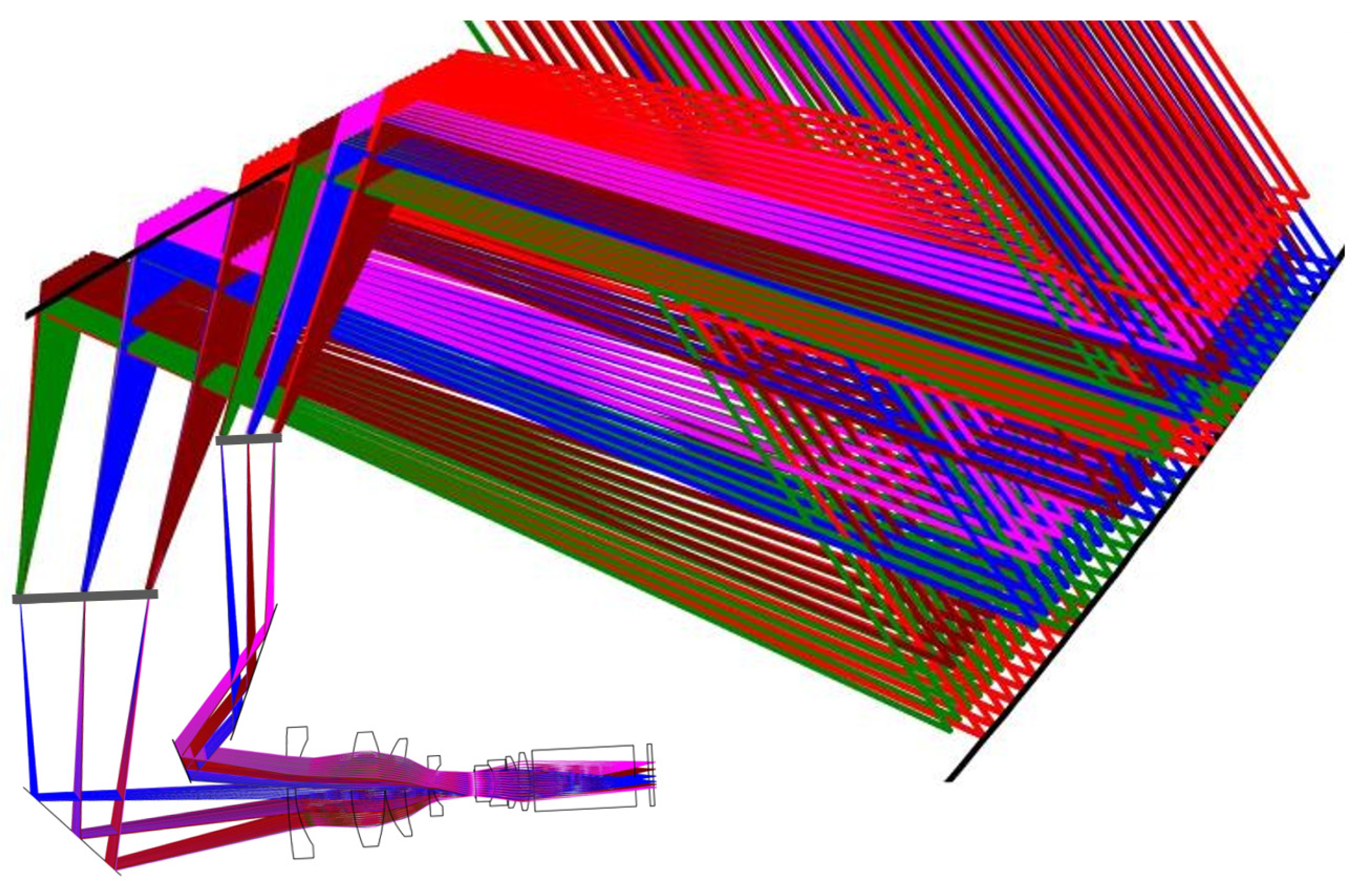
The final optimized optical system is shown in Figure 6, and Figure 7 shows the magnified view in the dotted box of Figure 6. The lateral and vertical relative distances of the image planes made by the optical system are 19.21 mm and 37.52 mm for the near-field and far-field virtual images, respectively.
3.3. Performance Analysis
The central eye point (E5) imaging quality of the optimized completed dual-focal-plane AR-HUD optical system is shown in Figure 7. The pupil diameter of the human eye is usually between 2 and 6 mm. To ensure the light filled the pupil, the pupil diameter was taken as 6 mm in this analysis.
Since the structure proposed in this paper is a dual-optical path design, it is necessary to evaluate the image quality of the far-field and near-field optical paths separately in the analysis. Figure 8 shows the spot diagram, MTF curve, and distortion grid diagram of the far-field and near-field configuration with the eye pupil located at the center of the eyebox, respectively.
Since the resolution of the digital micromirror devices (DMD) used in the PGU is 1152 × 576, the pixel pitch is 7.6 µm. The dimensions of the far-field and near-field image sources of the optimized AR-HUD were 110 mm × 31.5 mm and 97 mm × 13 mm, respectively. Hence, the projection objective magnification was at least 9.2×, and the Nyquist frequency of the AR-HUD was calculated as 7.2 lp/mm. The MTFs of the center position of the eyebox (E5) at the Nyquist frequency were all >0.5 and approached the diffraction limit. Meanwhile, from the spot diagram, the results of each FOV of the eyebox center converged within the Airy spot range, and the imaging quality of this evaluation point met the expected requirements.
The freeform coefficients of the primary mirror (PM) and secondary mirror (SM) after optimization are shown in Table 2. The PM dimensions were ~370 mm × 170 mm, and the SM dimensions were ~203 mm × 133 mm. To evaluate the freeform mirrors, we plotted the sag height maps of the PM and SM, as shown in Figure 9. Figure 10 shows the footprint diagrams of the primary and secondary mirrors when the eyebox range was filled with rays. Nine different colored color blocks in each diagram pair represent nine FOV points (F1~F9), with the larger blocks representing the footprint region of the far-field configuration, and the smaller blocks representing the footprint region of the near-field configuration. The size of each color block is related to the eye-movement range. The envelope rectangle of all color blocks on a single mirror represents all the rays of the ideal image at the current eye-movement range so that the human eye can see the complete near-field and far-field virtual images anywhere within the eyebox of the optimized AR-HUD optical system.
For the AR-HUD optical system, the size of the eyebox is much larger than the size of the eye pupil, so analyzing the imaging quality of only the five positions (E1 to E5) is not enough; thus, it is necessary to analyze as much as possible the imaging quality of each eye position in the eyebox to evaluate the whole optical system. For efficiency, the entire analysis process was implemented as a single program. Since the CODE V application programming interface (API) uses the Microsoft Windows standard component object model (COM) interface, users can execute CODE V commands using MATLAB, which supports the Windows COM architecture. Using the optical design software CODEV (https://www.synopsys.com/optical-solutions/codev.html) and Python communication, each position of the eye pupil in the eyebox was traversed in an automated manner, outputting the lowest MTF value and the largest aberration value for each position. The final imaging performance in the whole eyebox is shown in Figure 11.
The pupil distance of the human eyes is about 65 mm, so when both eyes observe the same image point, there will be a parallax between the two eyes. In a practical HUD, the binocular divergence parallax should be within 2.5 mrad to avoid visual discomfort [30,31]. Figure 12 shows the simulation results of the binocular divergence parallax when both eyes are located at the opposite edges of the eyebox, i.e., the worst case of interpupillary distance. The simulation results show that the binocular divergence parallax is less than 2.5 mrad for both near-field and far-field images. Therefore, a driver whose pupil distance is always less than the width of the eyebox will not be uncomfortable due to the divergence parallax.
To further simulate the effect of the designed dual-focal-plane AR-HUD, we created a simple user interface for real image simulation. We performed the reverse ray tracing of the designed optical system in Lighttools software (https://www.synopsys.com/optical-solutions/lighttools.html), and the simulation results are shown in Figure 13.
4. Projection Lens Design and Overall Evaluation
As the size of the designed AR-HUD near-field and far-field image sources are 110 mm × 31.5 mm and 97 mm × 13 mm, respectively, the magnification required for the projection objective lens is at least 9.2. To fully utilize the effective area of the DMD chip, the projection objective lens magnification was selected to be 9.2. The projection lens is designed in forward direction, i.e., the DMD chip is used as the image plane. The completed design of the projection lens and its MTF curve is shown in Figure 14, where the MTF is higher than 0.7 at 66 lp/mm. The total number of lenses in the projection lens is 8, and the total length is 90 mm. Figure 15 shows the field curves and the distortion curves, and it can be seen that the maximum distortion of the projection lens is lower than 1.3%.
To match the near-field and far-field image sources of the AR-HUD, the projection objective lens was divided into two design configurations. To facilitate plane reflection to fold the light path to different positions, the two configurations needed to be separated as much as possible to avoid interference between the plane reflector and imaging light path. To match the AR-HUD’s near-field and far-field image sources, the projection objective was also designed in two groupings. Additionally, to facilitate the use of plane mirrors to relay the optical path to different locations, it is necessary to separate the object surfaces of the two groupings as much as possible to avoid interference between the plane mirrors and the imaging optical path, and the final FOV was selected as shown in Figure 16.
The projection optics system after the flip is shown in Figure 17. To match the position of the image source of the AR-HUD in Figure 7, we folded the image plane of the projection objective lens. S1 and S2 are the near-field and far-field image sources of the AR-HUD, respectively, and are perpendicular to the DMD. The angle α1 of the tilt of M1 is 45°, the angle α2 of the tilt of M2 is 22°, and the angle α3 of the tilt of M3 is 20°. Since α2 + α3 is not equal to 45°, the projected near-field image has a slight trapezoidal distortion. The image quality of the final projection lens is shown in Figure 18, and the MTF values are all greater than 0.6 at 7.2 lp/mm with maximum distortion values of 1.25% for the far-field image and 1.3% for the near-field image.
5. Discussion of Results
The complete single PGU dual-focal-plane AR-HUD optical system is shown in Figure 19, where it can be noticed that the optical system designed in this paper collapses the optical path as much as possible to achieve volume control. The overall volume of the dual-focal-plane AR-HUD designed in this paper is about 16 L. Compared with other design solutions, this solution achieves a larger field of view and virtual image size in a medium volume, which further improves the augmented reality effect. The specific comparison is shown in Table 3.
Compared to the LCD as the PGU, the projection-type PGU makes it easier to prevent damage caused by sunlight backflow and improves product reliability. However, it is also a bit more expensive than the LCD when it comes to large-scale generation. The use of two freeform mirrors also makes the whole system more complex, further increasing the cost. Overall, it provides an alternative solution for AR-HUD design, and this design concept is conducive to the development of automotive intelligent cockpits. In the future, there is still room for AR-HUD improvement in terms of projection source heat dissipation, volume control, and surface profile error control during mass production of large-size freeform mirrors, in order to improve driving safety and man–machine efficiency.
6. Conclusions
This study proposes a new dual-focal-plane AR-HUD, which uses only a single projection-type PGU and two freeform mirrors. We use the step-by-step optimization approach for all sampled FOV points within the eyebox range and progressively constrain the distortion at each FOV point. A fully automated analysis program was also written to analyze the MTF and distortion values of the optical system over the entire eyebox range. The performance analysis shows that the optimized AR-HUD optical performance meets the requirements of the human eye. The maximum distortion values of the far field image (10 m, 13° × 4°) is 3.15% and the maximum distortion value of the near field image (3.5 m, 13° × 1.4°) is 3.58% over the entire eyebox range. The MTF values of both the near-field and far-field images are greater than 0.3. Finally, we also designed a projection lens for the AR-HUD optical system, which realizes two different depths of image plane through three plane mirrors to match the dual-focal-plane AR-HUD optical system. As the AR-HUD moves toward the larger FOV and longer VID, the design method of using a single PGU improves the efficiency of space utilization.
Author Contributions
C.F.: Conceptualization, methodology, conceptualization, software, validation, investigation, writing—original draft preparation; L.K.: Conceptualization, methodology, investigation, writing—review and editing; B.Y.: Project administration, funding acquisition, supervision, visualization; X.W.: Visualization, funding acquisition, project administration. All authors have read and agreed to the published version of the manuscript.
Funding
This research was funded by the Science and Technology Innovation Action Plan Project of Shanghai (No. 19511104600).
Institutional Review Board Statement
Not applicable.
Informed Consent Statement
Not applicable.
Data Availability Statement
The data used in this research are available from the corresponding author upon reasonable request.
Acknowledgments
The authors would like to thank the laboratory and university for their support.
Conflicts of Interest
The authors declare no conflict of interest.
References
- Liu, Y.C.; Wen, M.H. Comparison of head-up display (HUD) vs. head-down display (HDD): Driving performance of commercial vehicle operators in Taiwan. Int. J. Hum. Comput. Stud. 2004, 61, 679–697. [Google Scholar] [CrossRef]
- Smith, S.; Fu, S.H. The relationships between automobile head-up display presentation images and drivers’ Kansei. Displays 2011, 32, 58–68. [Google Scholar] [CrossRef]
- Qin, Z.; Lin, F.-C.; Huang, Y.-P.; Shieh, H.-P.D. Maximal acceptable ghost images for designing a legible windshield-type vehicle head-up display. IEEE Photonics J. 2017, 9, 7000812. [Google Scholar] [CrossRef]
- Horrey, W.J.; Wickens, C.D.; Alexander, A.L. The Effects of Head-Up Display Clutter and In-Vehicle Display Separation on Concurrent Driving Performance. Proc. Hum. Factors Ergon. Soc. Annu. Meet. 2003, 47, 1880–1884. [Google Scholar] [CrossRef]
- Mahajan, S.; Khedkar, S.B.; Kasav, S.M. Head-up display techniques in cars. Int. J. Eng. Sci. Innov. Technol. 2015, 4, 119–124. [Google Scholar]
- Ott, P. Optic design of head-up displays with freeform surfaces specified by NURBS. In Proceedings of the Optical Design and Engineering III, Glasgow, UK, 27 September 2008; pp. 339–350. [Google Scholar]
- Wei, S.; Fan, Z.; Zhu, Z.; Ma, D. Design of a head-up display based on freeform reflective systems for automotive applications. Appl. Opt. 2019, 58, 1675–1681. [Google Scholar] [CrossRef] [PubMed]
- Kim, K.-H.; Park, S.-C. Design of confocal off-axis two-mirror system for head-up display. Appl. Opt. 2019, 58, 677–683. [Google Scholar] [CrossRef]
- Ting, Z.; Jianyu, H.; Linsen, C.; Wen, Q. Status and prospect of augmented reality head up display. Laser Optoelectron. Prog. 2023, 60, 0811008–0811014. [Google Scholar]
- Gabbard, J.L.; Fitch, G.M.; Kim, H. Behind the glass: Driver challenges and opportunities for AR automotive applications. Proc. IEEE 2014, 102, 124–136. [Google Scholar] [CrossRef]
- Fan, R.; Wei, S.; Ji, H.; Qian, Z.; Tan, H.; Mo, Y.; Ma, D. Automated design of freeform imaging systems for automotive heads-up display applications. Opt. Express 2023, 31, 10758–10774. [Google Scholar] [CrossRef] [PubMed]
- Lee, J.-W.; Yoon, C.-R.; Kang, J.; Park, B.-J.; Kim, K.-H. Development of lane-level guidance service in vehicle augmented reality system. In Proceedings of the 2015 17th International Conference on Advanced Communication Technology (ICACT), Pyeongchang, Republic of Korea, 1–3 July 2015; pp. 263–266. [Google Scholar]
- Betancur, J.A.; Villa-Espinal, J.; Osorio-Gómez, G.; Cuéllar, S.; Suárez, D. Research topics and implementation trends on automotive head-up display systems. Int. J. Interact. Des. Manuf. 2018, 12, 199–214. [Google Scholar] [CrossRef]
- Seo, J.H.; Yoon, C.Y.; Oh, J.H.; Kang, S.B.; Yang, C.; LEE, M.R.; Han, Y.H. 59-4: A Study on Multi-depth Head-Up Display. SID 2017, 48, 883–885. [Google Scholar] [CrossRef]
- Foryou Multimedia Electronics Co., Ltd. Available online: http://www.adayome.com/E_detail01.html (accessed on 3 August 2023).
- Kim, K.-H.; Park, S.-C. Optical System Design and Evaluation for an Augmented Reality Head-up Display Using Aberration and Parallax Analysis. Curr. Opt. Photonics 2021, 5, 660–671. [Google Scholar]
- Kong, X.; Xue, C. Optical design of dual-focal-plane head-up display based on dual picture generation units. Acta Opt. Sin. 2022, 42, 1422003. [Google Scholar]
- Başak, U.Y.; Kazempourradi, S.; Ulusoy, E.; Ürey, H. Wide field-of-view dual-focal-plane augmented reality display. In Proceedings of the Advances in Display Technologies IX, San Francisco, CA, USA, 6–7 February 2019; pp. 62–68. [Google Scholar]
- Ma, S.; Hong, T.; Shi, B.; Li, D.; Wu, N.; Zhou, C. 57.6: Stray Light Suppression for a Dual Depth HUD System. SID 2019, 50, 635–637. [Google Scholar] [CrossRef]
- Shi, B.; Hong, T.; Wei, W.; Li, D.; Yang, F.; Wang, X.; Wu, N.; Zhou, C. 34.3: A Dual Depth Head Up Display System for Vehicle. SID 2018, 49, 371–374. [Google Scholar] [CrossRef]
- Qin, Z.; Lin, S.M.; Lu, K.T.; Chen, C.H.; Huang, Y.P. Dual-focal-plane augmented reality head-up display using a single picture generation unit and a single freeform mirror. Appl. Opt. 2019, 58, 5366–5374. [Google Scholar] [CrossRef]
- Liu, S.; Hua, H.; Cheng, D. A novel prototype for an optical see-through head-mounted display with addressable focus cues. IEEE Trans. Vis. Comput. Graph. 2009, 16, 381–393. [Google Scholar]
- Li, L.; Wang, Q.-H.; Jiang, W. Liquid lens with double tunable surfaces for large power tunability and improved optical performance. J. Opt. 2011, 13, 115503. [Google Scholar] [CrossRef]
- Zhan, T.; Lee, Y.-H.; Tan, G.; Xiong, J.; Yin, K.; Gou, F.; Zou, J.; Zhang, N.; Zhao, D.; Yang, J. Pancharatnam–Berry optical elements for head-up and near-eye displays. JOSA B 2019, 36, D52–D65. [Google Scholar] [CrossRef]
- Chen, H.-S.; Wang, Y.-J.; Chen, P.-J.; Lin, Y.-H. Electrically adjustable location of a projected image in augmented reality via a liquid-crystal lens. Opt. Express 2015, 23, 28154–28162. [Google Scholar] [CrossRef] [PubMed]
- Christmas, J.; Collings, N. 75-2: Invited Paper: Realizing Automotive Holographic Head Up Displays. SID 2016, 47, 1017–1020. [Google Scholar]
- Wakunami, K.; Hsieh, P.-Y.; Oi, R.; Senoh, T.; Sasaki, H.; Ichihashi, Y.; Okui, M.; Huang, Y.-P.; Yamamoto, K. Projection-type see-through holographic three-dimensional display. Nat. Commun. 2016, 7, 12954. [Google Scholar] [CrossRef] [PubMed]
- Teich, M.; Schuster, T.; Leister, N.; Zozgornik, S.; Fugal, J.; Wagner, T.; Zschau, E.; Häussler, R.; Stolle, H. Real-time, large-depth holographic 3D head-up display: Selected aspects. Appl. Opt. 2022, 61, B156–B163. [Google Scholar] [CrossRef]
- Yang, T.; Duan, Y.; Cheng, D.; Wang, Y. Freeform imaging optical system design: Theories, development, and applications. Acta Opt. Sin. 2021, 41, 0108001. [Google Scholar] [CrossRef]
- Gish, K.W.; Staplin, L. Human Factors Aspects of Using Head Up Displays in Automobiles: A Review of the Literature; Report DOT HS 808 320; National Highway Traffic Safety Administration, U.S. Department of Transportation: Washington, DC, USA, 1995.
- AS8055; Minimum Performance Standard for Airborne Head up Display (HUD). SAE International: Warrendale, PA, USA, 2015.
- SAIC Volkswagen Automotive Co., Ltd. Available online: https://www.svw-volkswagen.com/id4x/ (accessed on 18 September 2023).
Figure 1.
Schematic of the structure of the complete AR-HUD optical system.

Figure 2.
Schematic diagram of dual-focal-plane AR-HUD parameters. (a) Schematic of the field of view setup; (b) schematic of the eye pupil and eyebox.
Figure 2.
Schematic diagram of dual-focal-plane AR-HUD parameters. (a) Schematic of the field of view setup; (b) schematic of the eye pupil and eyebox.
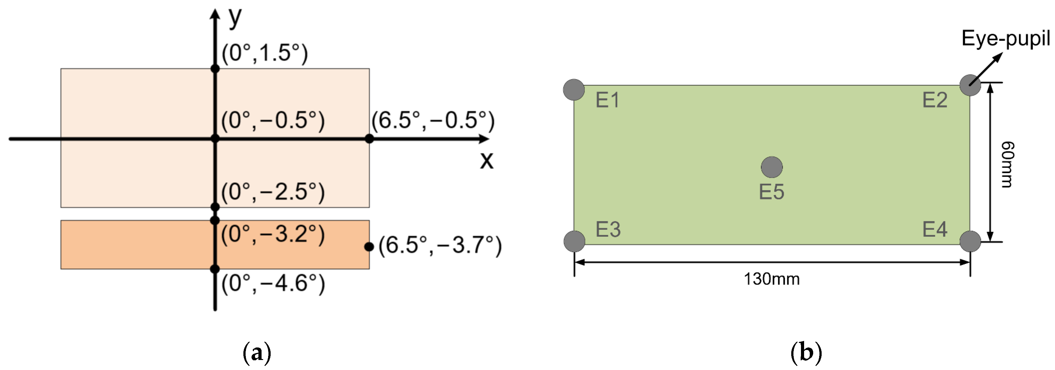
Figure 3.
Optimization process field of view settings. (a) Pre- and mid-optimization; (b) post-optimization.
Figure 3.
Optimization process field of view settings. (a) Pre- and mid-optimization; (b) post-optimization.

Figure 4.
Schematic diagram of structural constraints.

Figure 5.
AR-HUD distortion control charts.
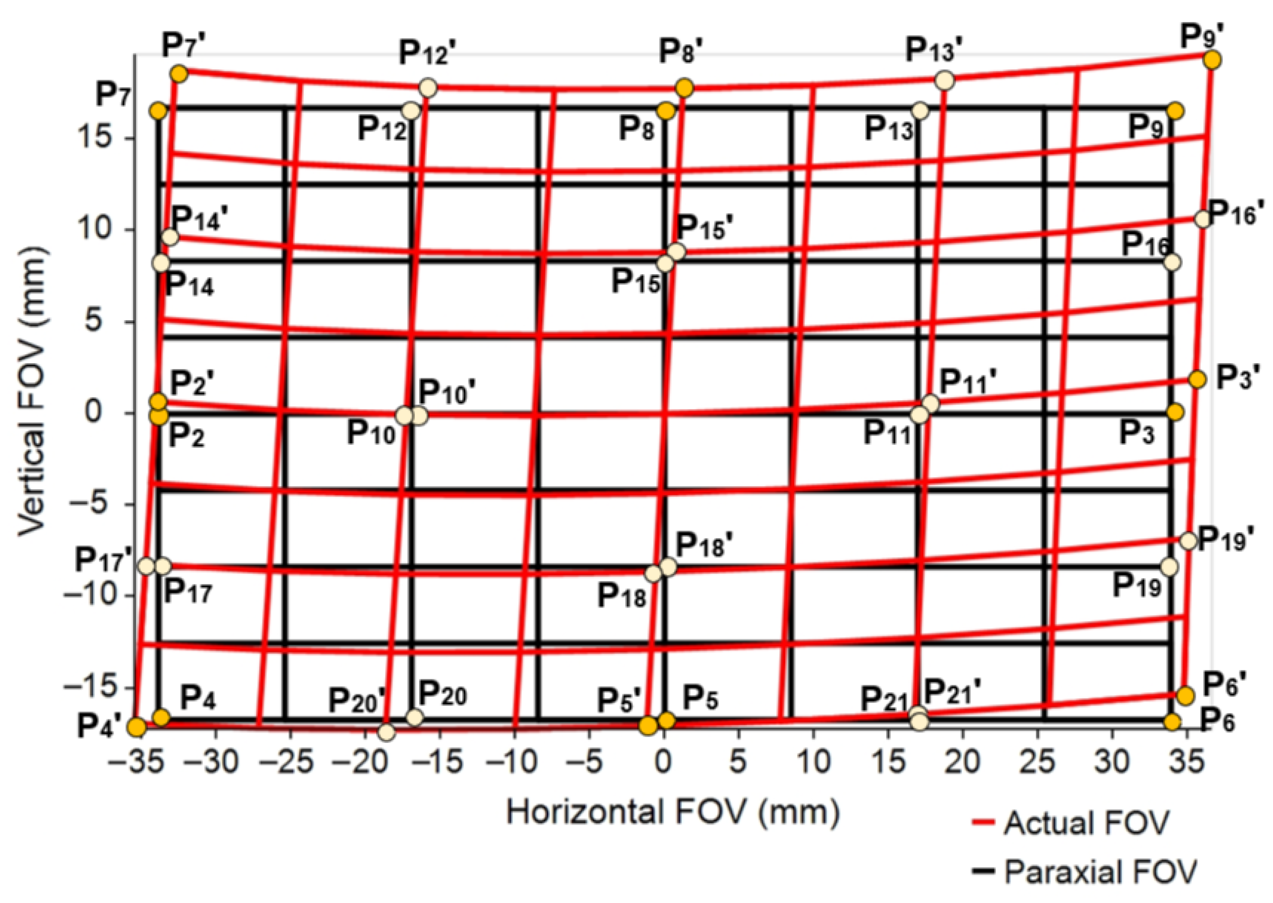
Figure 6.
Structure of AR-HUD after optimization was completed.
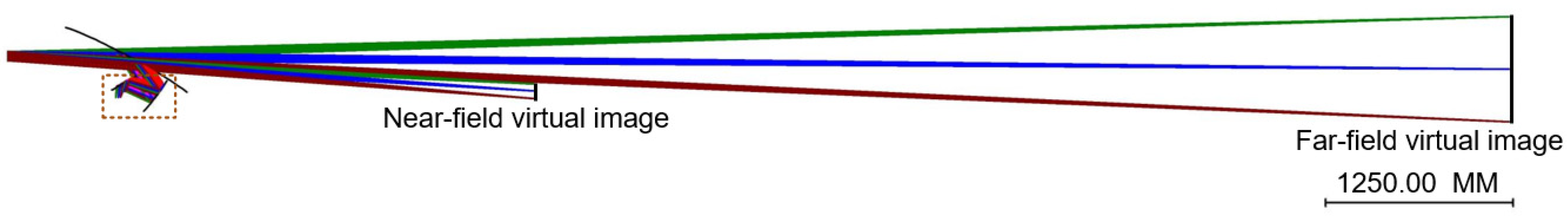
Figure 7.
Enlarged view of dashed box in Figure 6.
Figure 7.
Enlarged view of dashed box in Figure 6.
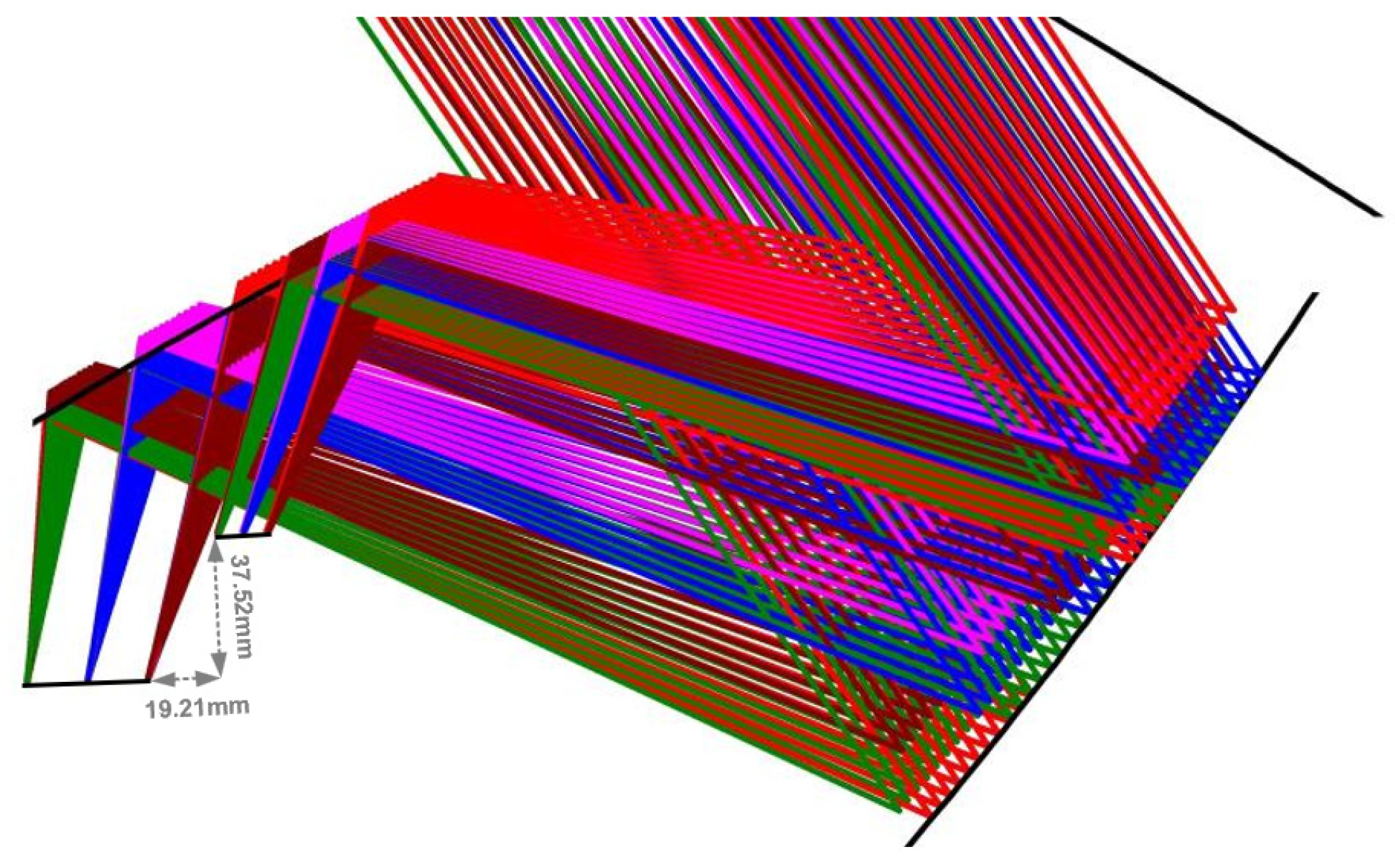
Figure 8.
Performance analysis of the eye pupil at the eyebox center position of the AR-HUD. (a) Far-field configuration spot diagram; (b) far-field configuration MTF curve; (c) far-field configuration aberration grid diagram; (d) near-field configuration spot diagram; (e) near-field configuration MTF curve; (f) near-field configuration aberration grid diagram.
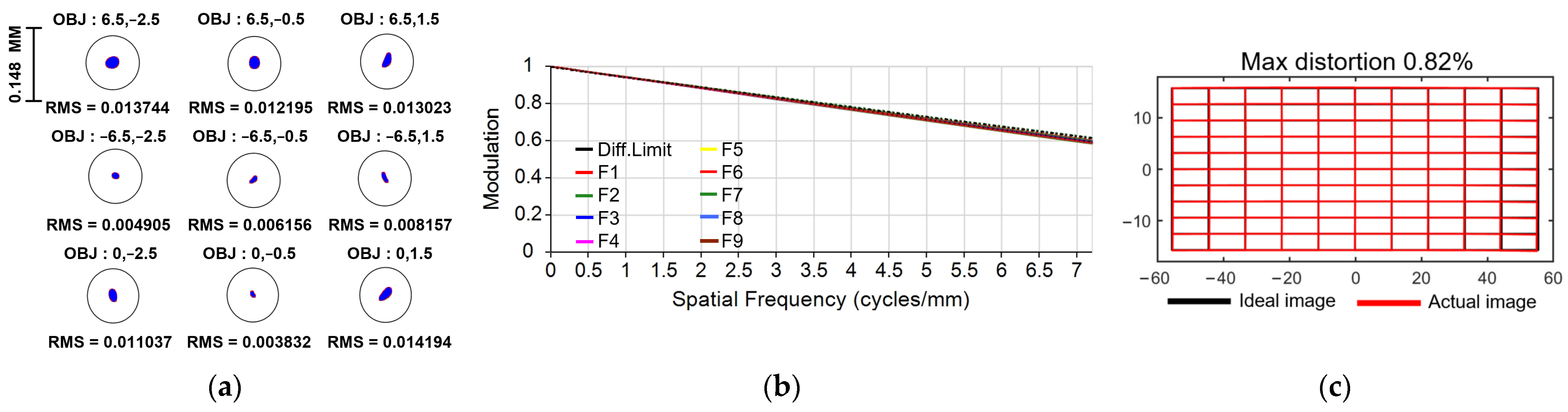

Figure 9.
Surface sag maps. (a) PM; (b) SM.
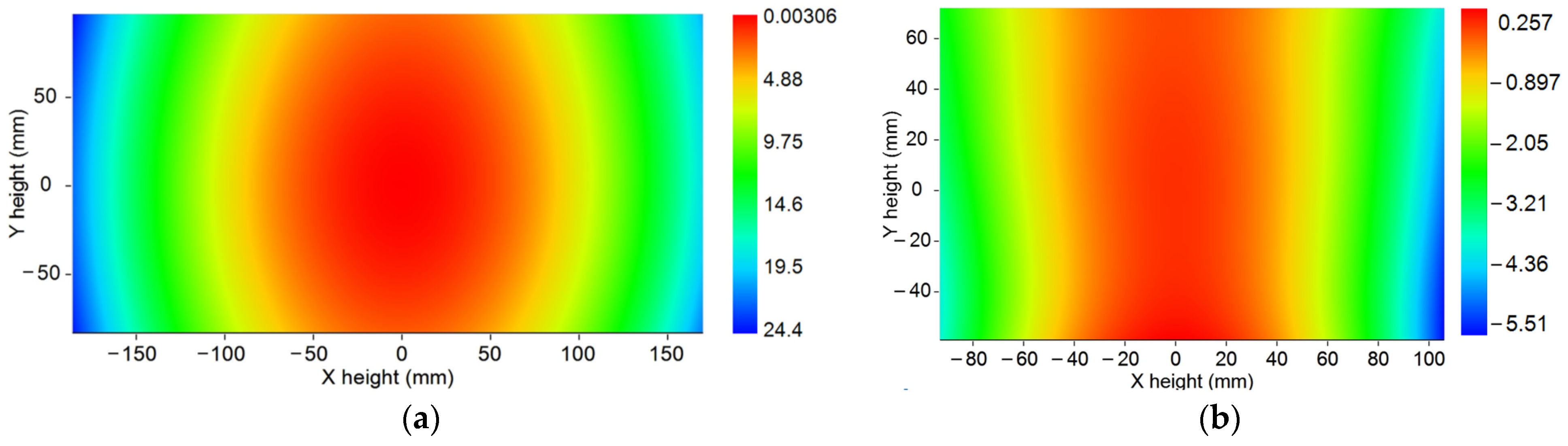
Figure 10.
Footprint diagrams. (a) PM; (b) SM.
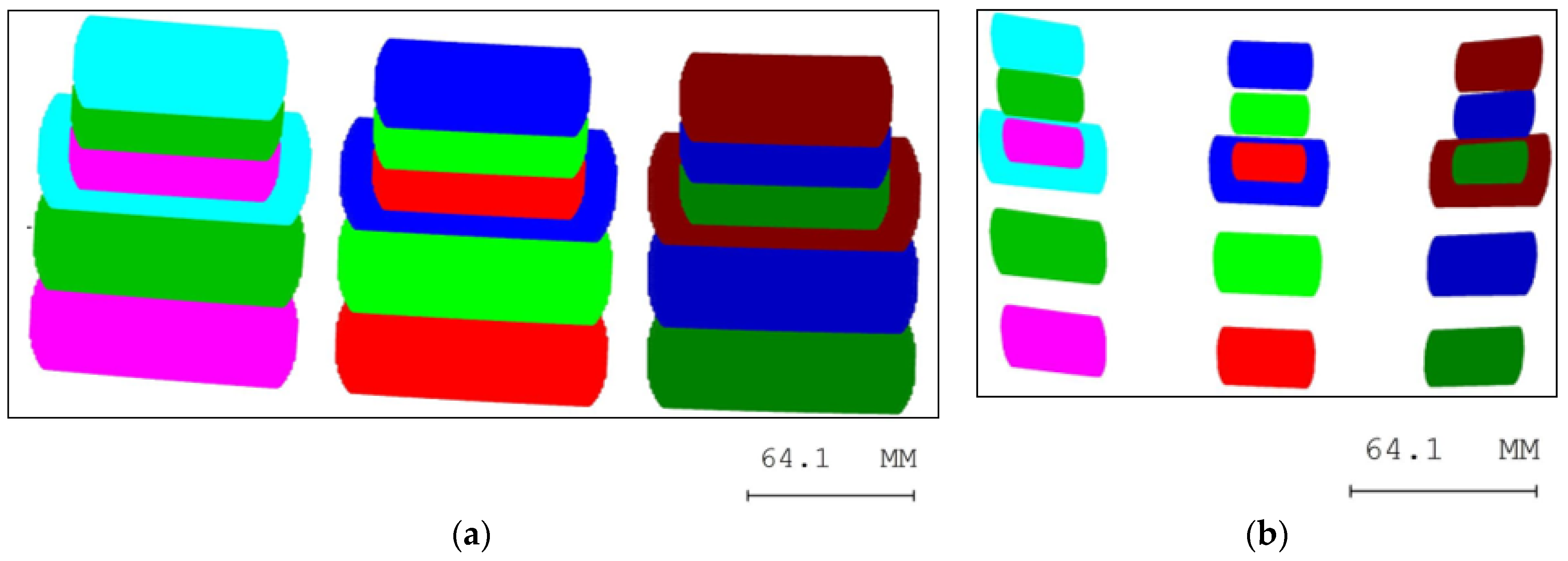
Figure 11.
Imaging performance in the entire eyebox. (a) Minimum MTF value for the full FOV at each eye-pupil position in the far-field configuration; (b) maximum distortion value for each eye pupil position in the far-field configuration; (c) minimum MTF value for the full FOV at each eye-pupil position in the near-field configuration; (d) minimum distortion value for each eye pupil position in the far-field configuration.
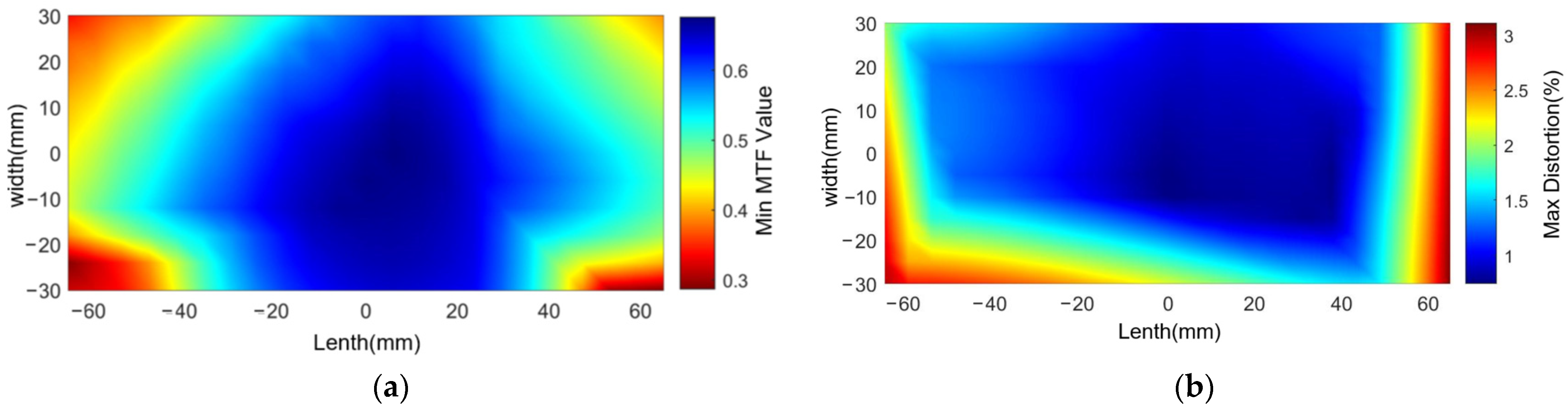

Figure 12.
Binocular divergence parallax analysis results. (a) Results of far-field image analysis when both eyes are at E1 and E2 positions, respectively; (b) results of near-field image analysis when both eyes are at positions E1 and E2, respectively; (c) results of far-field image analysis when both eyes are at positions E3 and E4, respectively; (d) results of near-field image analysis when both eyes are at positions E3 and E4, respectively.
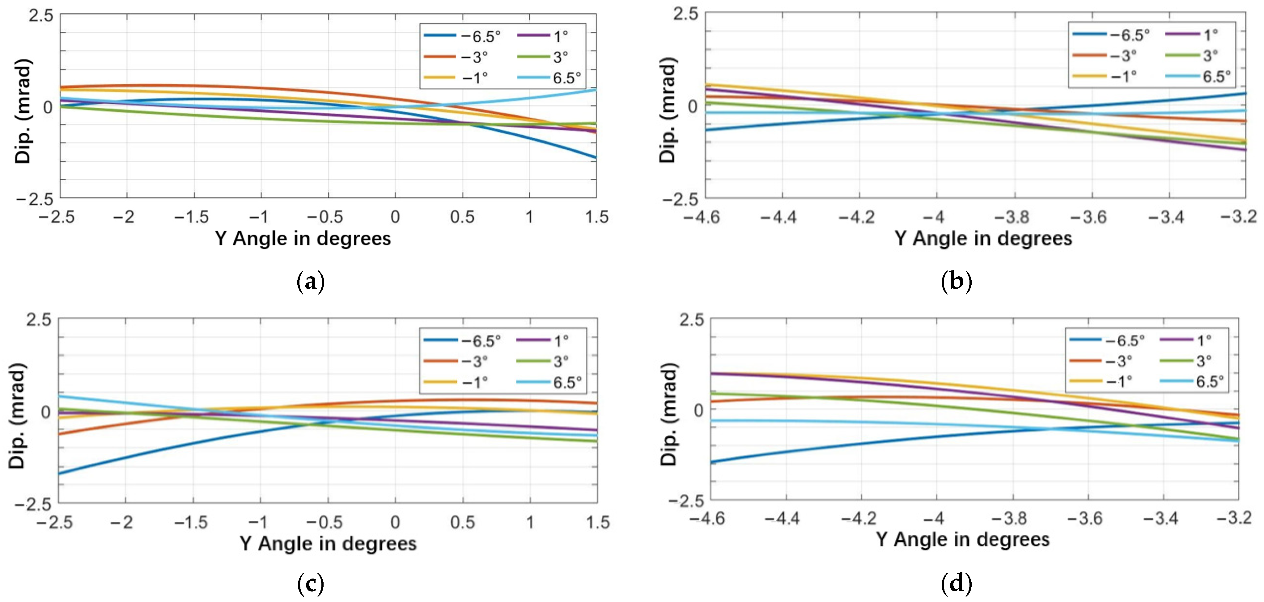
Figure 13.
Image simulation results. (a) Eye pupil at the leftmost side of the eyebox; (b) eye pupil at the center of the eyebox; (c) eye pupil at the rightmost side of the eyebox.
Figure 13.
Image simulation results. (a) Eye pupil at the leftmost side of the eyebox; (b) eye pupil at the center of the eyebox; (c) eye pupil at the rightmost side of the eyebox.
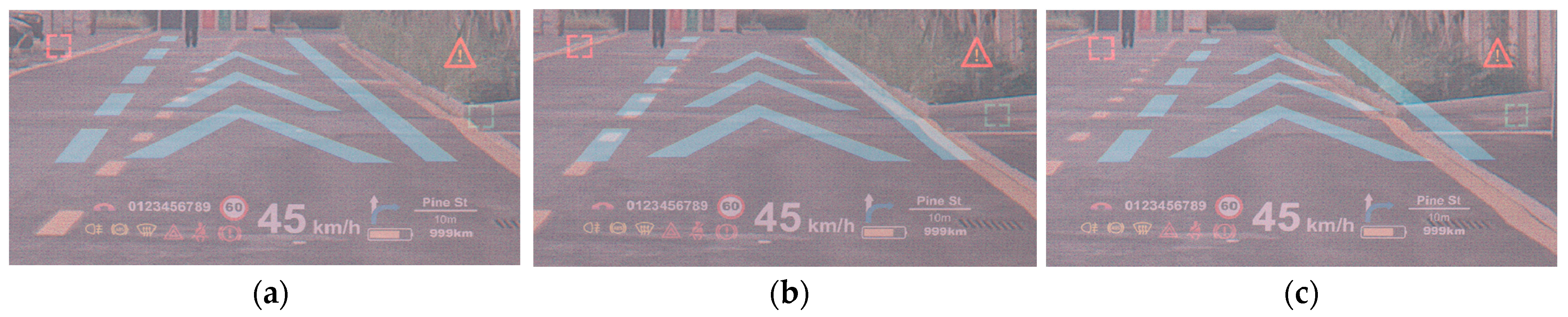
Figure 14.
Design results of the projection lens and its MTF curve.

Figure 15.
Field curves and distortion curves of the projection lens.
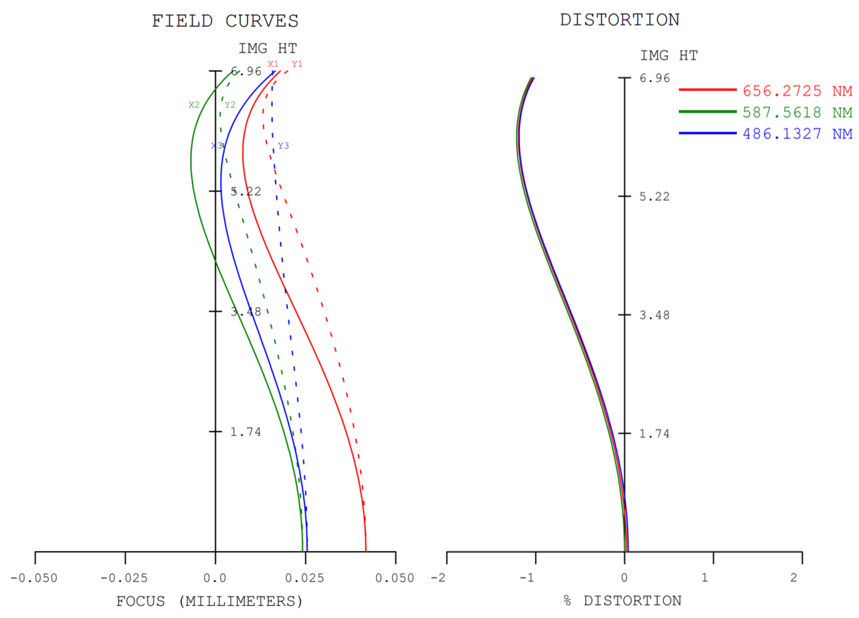
Figure 16.
Schematic diagram of the field of view setting of the projection lens.
Figure 17.
Final design layout of the projection lens.

Figure 18.
The results of the projection lens performance analysis. (a) Far-field configuration MTF curve; (b) far-field configuration distortion grid; (c) near-field configuration MTF curve; (d) far-field configuration distortion grid.
Figure 18.
The results of the projection lens performance analysis. (a) Far-field configuration MTF curve; (b) far-field configuration distortion grid; (c) near-field configuration MTF curve; (d) far-field configuration distortion grid.
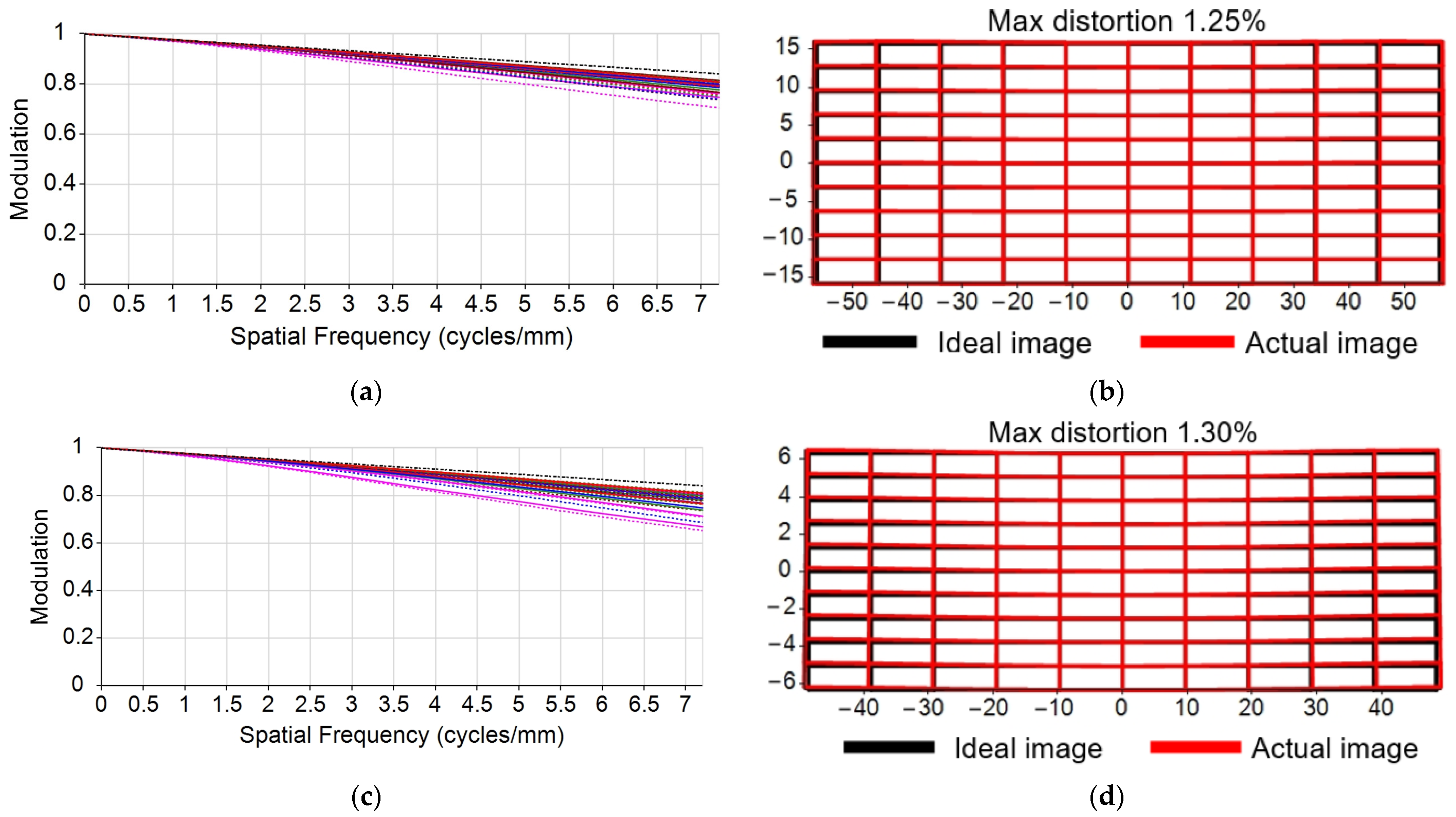
Figure 19.
Final complete layout of the dual-focal-plane AR-HUD.


Table 1.
Specifications of the designed HUD.
| Parameter | Value |
|---|---|
| FOV | Far: 13° × 4° Near: 13° × 1.4° |
| VID | Far: 10 m Near: 3.5 m |
| Eyebox size | 130 mm × 60 mm |
| Distortion | <5% |
| Pupil diameter | 6 mm |
| Modulation transfer function (MTF) @ Nyquist frequency | >0.3 lp/mm |
Table 2.
Freeform coefficients of the primary mirror and secondary mirror after optimization.
| xmyn Item | PM | SM |
|---|---|---|
| x | / | −3.690 × 10⁻⁵ |
| y | / | −9.107 × 10⁻¹⁷ |
| x2 | −7.694 × 10⁻⁵ | −4.278 × 10⁻⁴ |
| xy | 2.114 × 10⁻⁵ | −2.338 × 10⁻⁵ |
| y2 | 2.352 × 10⁻⁴ | −3.614 × 10⁻⁵ |
| x3 | −3.691 × 10⁻⁸ | −1.816 × 10⁻⁷ |
| x2y | 1.411 × 10⁻⁷ | 1.261 × 10⁻⁶ |
| xy2 | −4.745 × 10⁻⁸ | −9.538 × 10⁻⁸ |
| y3 | 2.666 × 10⁻⁷ | −9.404 × 10⁻⁷ |
| x4 | −1.047 × 10⁻¹⁰ | 1.749 × 10⁻¹⁰ |
| x3y | −3.501 × 10⁻¹² | 2.898 × 10⁻¹⁰ |
| x2y2 | 2.373 × 10⁻¹⁰ | 1.284 × 10⁻¹⁰ |
| x2y3 | 9.535 × 10⁻¹⁰ | 3.851 × 10⁻⁹ |
| y4 | 4.867 × 10⁻⁹ | 1.407 × 10⁻⁸ |
Table 3.
Comparison of the dual-focal-plane AR-HUD designed in this paper with others’ designs.
| Qin’s [21] | Shi’s [20] | Volkswagen ID4′s [32] | Ours | |
|---|---|---|---|---|
| FOV | Far: 10° × 3° Near: 6° × 2° | Far: 10° × 5° Near: 5° × 1° | Far: 9° × 4° Near: 7° × 1° | Far: 13° × 4° Near: 13° × 1.4° |
| VID | Far: 9 m Near: 2.5 m | Far: 7.8 m Near: 2.7 m | Far: 10 m Near: 3 m | Far: 10 m Near: 3.5 m |
| Eyebox size | 120 mm × 60 mm | 150 mm × 80 mm | / | 130 mm × 60 mm |
| Volume | 8.5 L | 30 L | 14 L | 16 L |
| PGU | Single LCD | Two LCDs | Two LCDs | Single DLP |
| Distortion | <3.05% | <3.60% | / | <3.58% |
Disclaimer/Publisher’s Note: The statements, opinions and data contained in all publications are solely those of the individual author(s) and contributor(s) and not of MDPI and/or the editor(s). MDPI and/or the editor(s) disclaim responsibility for any injury to people or property resulting from any ideas, methods, instructions or products referred to in the content. |
© 2023 by the authors. Licensee MDPI, Basel, Switzerland. This article is an open access article distributed under the terms and conditions of the Creative Commons Attribution (CC BY) license (https://creativecommons.org/licenses/by/4.0/).
Share and Cite
MDPI and ACS Style
Fan, C.; Kong, L.; Yang, B.; Wan, X. Design of Dual-Focal-Plane AR-HUD Optical System Based on a Single Picture Generation Unit and Two Freeform Mirrors. Photonics 2023, 10, 1192. https://doi.org/10.3390/photonics10111192
AMA Style
Fan C, Kong L, Yang B, Wan X. Design of Dual-Focal-Plane AR-HUD Optical System Based on a Single Picture Generation Unit and Two Freeform Mirrors. Photonics. 2023; 10(11):1192. https://doi.org/10.3390/photonics10111192
Chicago/Turabian StyleFan, Chengxiang, Lingbao Kong, Bo Yang, and Xinjun Wan. 2023. "Design of Dual-Focal-Plane AR-HUD Optical System Based on a Single Picture Generation Unit and Two Freeform Mirrors" Photonics 10, no. 11: 1192. https://doi.org/10.3390/photonics10111192
Note that from the first issue of 2016, this journal uses article numbers instead of page numbers. See further details here.