Free Space Optical Communication: An Enabling Backhaul Technology for 6G Non-Terrestrial Networks


1
Department of Electrical and Electronics Engineering, Özyeǧin University, Istanbul 34794, Turkey
2
Engineering Division, New York University Abu Dhabi (NYUAD), Abu Dhabi P.O. Box 129188, United Arab Emirates
3
Center of Excellence in Optical Wireless Communication Technologies, Özyeǧin University, Istanbul 34794, Turkey
*
Authors to whom correspondence should be addressed.
Photonics 2023, 10(11), 1210; https://doi.org/10.3390/photonics10111210
Submission received: 5 September 2023
/
Revised: 16 October 2023
/
Accepted: 26 October 2023
/
Published: 30 October 2023
(This article belongs to the Special Issue Free Space Optics-Based 6G Non-terrestrial Networks)
Abstract
:The deployment of non-terrestrial networks (NTNs) is envisioned to achieve global coverage for 6G and beyond. In addition to space nodes, aerial NTN nodes such as high-altitude platform stations (HAPSs) and rotary-wing unmanned aerial vehicles (UAVs) could be deployed, based on the intended coverage and operational altitude requirements. NTN nodes have the potential to support both wireless access and backhauling. While the onboard base station provides wireless access for the end users, the backhauling link connects the airborne/space-borne base station to the core network. With its high data transmission capability comparable to fiber optics and its ability to operate in the interference-free optical spectrum, free space optical (FSO) communication is ideally suited to backhauling requirements in NTNs. In this paper, we present a comprehensive tutorial on airborne FSO backhauling. We first delve into the fundamentals of FSO signal transmission and discuss aspects such as geometrical loss, atmospheric attenuation, turbulence-induced fading, and pointing errors, all of which are critical for determining received signal levels and related link budget calculations. Then, we discuss the requirements of airborne backhaul system architectures, based on use cases. While single-layer backhaul systems are sufficient for providing coverage in rural areas, multi-layer designs are typically required to establish connectivity in urban areas, where line of sight (LoS) links are harder to maintain. We review physical layer design principles for FSO-based airborne links, discussing both intensity modulation/direct detection (IM/DD) and coherent modulation/coherent demodulation (CM/CD). Another critical design criteria for airborne backhauling is self-sustainability, which is further discussed in our paper. We conclude the paper by discussing current challenges and future research directions. In this context, we discuss reconfigurable intelligent surfaces (RIS) and spatial division multiplexing (SDM), for improved performance and an extended transmission range. We emphasize the importance of advanced handover techniques and scalability issues for practical implementation. We also highlight the growing role of artificial intelligence/machine learning (AI/ML) and their potential applications in the design and optimization of future FSO-based NTNs.
1. Introduction
The deployment of Non-Terrestrial Network (NTNs) is envisioned to realize truly global coverage for 6G and beyond. NTNs have the potential to support different segments of the network, including wireless access, backhauling, and the backbone [1,2,3,4,5,6,7,8,9,10,11,12], as illustrated in Figure 1. Wireless access refers to the use of wireless technologies to connect end users to the network. NTNs can provide wireless access over large geographical areas where terrestrial, infrastructure is limited or absent, such as remote and underserved areas. In urban areas, NTN-based wireless access can be positioned as a complementary solution. For example, they can be deployed for events with temporary high-traffic demands, e.g., concerts, football games, and other live events. NTNs can also provide global wireless access to mobile end users, regardless of their geographical location. For example, end users on a transatlantic cruise, or country-wide high-speed trains can access the Internet via NTNs, even if terrestrial infrastructure is not available. NTNs are also instrumental in post-disaster scenarios, for providing service to mobile users in affected areas where ground base stations are partly or fully damaged.
Backhaul is the link between the access network and the backbone/core network. This connectivity is typically established using fiber optics or terrestrial point-to-point wireless links, e.g., microwave or Millimeter Wave (MMW) links. Fiber optic infrastructure offers an ultra-high operational capacity, enabling the transmission of large amounts of data at high speeds over long distances. It provides excellent reliability, low latency, and superior signal quality compared to other transmission media. However, deploying fiber optics requires significant financial investment, as it involves laying down physical cables and establishing the necessary infrastructure. Extending fiber optic connectivity to remote or geographically challenging areas, such as rural regions or mountainous terrain, can be particularly challenging. While fiber optic infrastructure is available in major cities, the processes of obtaining the required permits, trenching, installing, and maintaining of fiber optic cables can be complex and time-consuming, which further limits their use in urban environments. For example, to address the user density and high-peak traffic demands in urban areas, small cells, i.e., low-power base stations with small coverage areas, are typically deployed in addition to macro cells. However, it is not possible to extend the fiber optic infrastructure to every small cell, due to space constraints, regulatory issues, and high installation costs.
As a result of the aforementioned limitations, and despite the significant ongoing investments in fiber optics, wireless backhauling has become the preferred choice for mobile operators, since it offers greater flexibility in reaching remote or difficult areas. According to market projections [13,14], wireless backhauling is projected to account for 65% of global backhaul links within the time frame of 2021–2027. The market trends in favor of wireless backhauling give a unique opportunity for NTN-based solutions, which can be particularly cost-effective for rural areas, isolated regions, rugged terrains, or remote islands, which would otherwise be difficult to reach through traditional terrestrial infrastructure. Similarly, NTN-based backhauling might be an ideal solution for small cells in urban areas.
The backhaul links discussed above can be considered distribution networks that connect the points of presence to the backbone. The backbone network is typically composed of high-speed fiber optic cables. These cables are laid along major routes and interconnected with network nodes, such as data centers and telecommunication exchanges, to ensure seamless communication between the different parts of the network. It forms the core of the telecommunications network and provides connectivity between different regions, cities, and countries. Non-terrestrial backbone networks can extend connectivity to remote and underserved regions where the terrestrial backbone infrastructure is non-existent or limited. Furthermore, they can enhance the resilience and redundancy of the overall telecommunication infrastructure. By diversifying the network infrastructure with non-terrestrial solutions, the risk of single points of failure or disruptions in communication can be mitigated [15]. In the event of terrestrial infrastructure damage or outages, NTNs can provide alternative routes for communication, ensuring continuity of services.
As illustrated in Table 1, NTNs include variants of space-borne and aerial nodes. Space-borne nodes include satellites in Geostationary Orbit (GEO), Medium Earth Orbit (MEO), and Low Earth Orbit (LEO). Airborne nodes take the form of High-Altitude Platform Station (HAPSs), and Unmanned Aerial Vehicle (UAVs).
HAPSs are also known as high-altitude pseudo-satellites and operate in the stratospheric layer at altitudes of 17–22 km [19]. This operation altitude is above the maximum altitude for commercial flights and above the clouds. HAPS can remain airborne through aerodynamic means (resembling airplanes) or aerostatic means, such as balloons or airships [17].
Unlike HAPSs, UAVs operate at lower operational altitudes (i.e., the troposphere) in the range of a few dozen meters to several km [20]. UAVs can take the form of a fixed-wing or rotary-wing types. Rotary-wing UAVs are typically designed to operate at altitudes up to a few km. They have different configurations, such as quadcopters, hexacopters, etc., depending on the number of rotors employed for lift and control. These UAVs utilize vertically oriented propellers to generate upward thrust and maintain flight. By adjusting the speed and angles of their rotors, UAVs can alter their altitude, direction, and orientation. Multirotor UAVs have the ability to take off vertically, hover in a fixed/semi-fixed position, and have the ability to maneuver. Fixed-wing UAVs are typically designed to serve at higher altitudes within the troposphere. For example, the military-type MQ-9 Reaper [21] can fly at an altitude up to around 15 km. ScanEagle [22] is an example of a civilian fixed-wing UAV, with an operation altitude of around 6 km.
1.1. Space-Borne Nodes
In 1945, the British science fiction writer and inventor Arthur C. Clarke published an article titled “Extra-Terrestrial Relays” in the magazine Wireless World, where he proposed the concept of GEO satellites [23]. He described how these satellites, positioned in a specific orbit above the Earth’s equator, could remain fixed relative to a specific location on the Earth’s surface, providing continuous coverage for communication purposes. The realization of Clarke’s vision took a significant step forward with the launch of the first artificial satellite, Sputnik, by the Soviet Union in 1957 [24]. Although Sputnik did not have direct telecommunication capabilities, its launch demonstrated the feasibility of placing objects in orbit around the Earth and opened the door for future satellite-based communication systems. Following the launch of Sputnik, the development of satellite communication systems progressed rapidly. In 1962, the first active communication satellite, Telstar 1, was launched into space. Telstar 1 enabled the transmission of television signals, telephone calls, and other data across the Atlantic Ocean, demonstrating the potential of satellite communication for global connectivity [25].
Since then, numerous satellites have been launched into various orbits, including GEO, MEO, and LEO, to support telecommunication services [26]. For example, the International Maritime Satellite Organization (INMARSAT) operates four geostationary satellites at different orbital positions, to provide global coverage to around 97% of the Earth’s surface [27] [Section 1.1.3]. Other examples of GEO satellite systems include International Telecommunications Satellite Organization (Intelsat), Société Européenne des Satellites (SES), Communications Satellite Corporation (Comsat), European Telecommunications Satellite Organization (Eutelsat), and Canadian Telecommunications Satellite (Telesat). These satellite operators deploy GEO satellites to provide a wide range of communication services, including television broadcasting, broadband internet access, and telecommunication services.
Despite offering worldwide continuous coverage by maintaining a stationary position over a particular area in a synchronized orbit, GEO satellites face restricted data rates. Furthermore, the significant delay in signal propagation resulting from their high altitude introduces noticeable latency and hence adversely affects real-time applications. This prompted the idea of providing global wireless coverage through LEO satellites, which was first considered in the 1990s. In 1993, Motorola launched the Iridium constellation, which consists of 66 LEO satellites that formed a mesh network [27,28]. In this mesh network, signals were relayed between satellites and eventually reached their intended destinations on Earth. The Iridium system was designed to provide mainly voice services, as well as low-rate data services up to 10 kbps [27] [Section 1.3.3.6]. Iridium, however, experienced financial and technical challenges due to the high cost of infrastructure development. The high cost of service made it unattractive and expensive for users [29]. Another early LEO constellation launched to provide global satellite communications coverage was Globalstar, which initially comprised 48 satellites [30]. The company began offering customers mobile voice and data services worldwide in 2002. The data rate provided by the first Globalstar system was around 9.6 kbps and allowed voice calls, short messaging, and limited data transfer. Similar to Iridium, its success was limited. Another early LEO constellation example is Teledesic, which ceased operations in 2002 [31] [Section 1.13].
The first-generation LEO satellites mainly failed, due to their inability to meet expectations. First of all, there was a limitation on the capacity of the early LEO satellites, both in terms of simultaneous users and the amount of data they were capable of handling. For example, the data rate provided by the Iridium system was limited to 10 kbps. This data rate was also shared among multiple users connected to the system [26] [Section 7.2]. In addition, the whole Iridium system of 66 LEO satellites could only serve thousands of users worldwide. Due to their inherent limitations, they could not support many users with high-speed and reliable communications services. Coverage areas were often limited to specific regions or countries.
As a rebirth of NTNs, various companies have recently launched LEO mega satellite constellations, e.g., Starlink, Kuiper, and OneWeb, which can be considered a second generation. Starlink, a project led by SpaceX, plans to deploy thousands of small satellites in LEO at an altitude of 550 km [32], creating a vast network that will cover a large part of the planet and communicate with other satellites and ground stations. Starlink will offer download speeds ranging from 25 to 220 Mbps. Most users are expected to experience speeds exceeding 100 Mbps. Upload speeds will fall within the range of 5 to 20 Mbps. Latency is expected to be between 25 and 60 ms on land, while certain remote locations such as oceans, islands, Antarctica, Alaska, and Northern Canada may encounter latencies of more than 100 ms [33]. As of December 2021, Starlink has launched 1969 satellites, serving 140,000 users in 20 countries, and is planning to extend this to a total of 42,000 LEO satellites before the end of this decade [34].
Another mega-constellation under planning is Amazon Kuiper [35]. This constellation is designed to consist of 3236 satellites deployed in LEO altitudes between 590 km and 630 km. These satellites will be positioned at an altitude that is around 67 km closer to the ground than Starlink, which is expected to result in a relatively lower latency. In terms of data rate, it has been reported that Kuiper customer terminals could reach a speed of 400 Mbps, with expectations for further improvements in future versions [36].
The OneWeb LEO satellite constellation [37] consists of 648 satellites positioned approximately 1200 km above Earth. The constellation is designed to primarily serve businesses, governments, phone network operators, and clusters of communities, rather than individual domestic customers. OneWeb utilizes optical inter-satellite communication systems [38], which allow for efficient communication between the satellites in the constellation, enhancing the network’s overall performance [38]. The access strategy of the gateway stations in OneWeb’s constellation is relatively more complex, due to the repeated coverage of the same gateway station by multiple satellites [39].
The deployment of mega satellite constellations by these companies represents a significant advancement in the field of telecommunications. By leveraging the advantages of satellites in LEO, such as low latency and global coverage, these constellations have the potential to revolutionize internet connectivity and extend cellular services to previously underserved areas. As technology continues to evolve, it is expected that more companies and researchers will join the effort.
1.2. Airborne Nodes
In addition to space nodes, aerial NTN nodes in the form of UAVs and HAPSs can be deployed based on the intended coverage and operation altitude requirements. Rotary-wing UAVs in different form factors are already available from different manufacturers and cover lower altitudes, typically up to a few kilometers. For example, base stations can be mounted on rotary-wing UAVs to provide wireless access, e.g., Nokia F-Cell [40] and AT&T’s Cell on Wings (COW) [41]. The Nokia F-Cell system consists of a 64-antenna massive Multiple-Input Multiple-Output (MIMO) system that is used to create eight beams. It can handle multiple channels simultaneously and achieve a system throughput rate of about 1 Gbps over existing Long-Term Evolution (LTE) networks [40]. AT&T’s COW is a tethered UAV that provides cellular coverage across around 100 km2 area [42]. Their primary purpose is to serve as a cellular and data bridge to the internet for AT&T’s First Responder “FIRSTNET” network, ensuring critical connectivity in disaster areas [43].
Advances in autonomous avionics and composite materials have also made possible the development of lightweight and long-endurance HAPSs for operation in the stratospheric layer, at altitudes of 17–22 km. In comparison to LEO satellites, they can provide a much lower latency and have the potential for a higher data rate capacity delivered per unit area. HAPS can be also seen as more environmentally friendly solutions compared to satellites. For example, it was discussed in [44] that the increasing number of LEO mega-constellations increases the risk of collisions and may result in space debris. By virtue of their operation, HAPS avoid such disadvantages associated with LEO satellites. HAPSs also have lower launch and recovery costs than satellite systems and are more cost-effective solutions. By achieving higher data rate capacities per unit area, HAPS are able to deliver enhanced communication and data transmission capabilities to specific target regions, due to their smaller footprints. Moreover, HAPSs provide a lower latency by being much closer to the Earth’s surface, reducing signal travel times and allowing faster responses for real-time applications.
Recent examples of aerostatic HAPS include the Thunderhead Balloon [45], Google’s Loon [46], and Sceye [47]. Raven Aerostar has developed the Thunderhead Balloon, which is an aerostatic HAPS. These are polyethylene-made, pumpkin-shaped super-pressure balloons available in multiple sizes. They have a volume ranging from 1812 to 11,327 m3 and can achieve flight altitudes between 15 and 20 km for the smaller models and between 22 and 28 km for the larger ones [48]. They have a payload capacity of around 55 kg, i.e., they can typically carry communication equipment, cameras, and other sensors for various monitoring and data-gathering purposes. For maintaining a stable position in the stratosphere, the balloon is equipped with sophisticated navigation and control systems.
As another example, the Loon project (developed by Google X) was intended to provide internet access to remote and rural areas by means of balloons at an average altitude of around 20 km. The payload of Loon is in the range of 10 kg and it has a flying time that surpasses 100 days [49,50,51]. These balloons were maneuvered by adjusting their altitude in the stratosphere based on wind data. Project Loon was terminated in January 2021, due to technical and operational challenges.
Renewed interest has arisen in the development of solar-powered aerodynamic HAPS with extended flight endurance. Recent examples include Facebook’s Aquila [52], Airbus’s Zephyr [53], Softbank’s Sunglider [54], Korea Aerospace Research Institute (KARI) EAV-3 [55], High Altitude Long Endurance Unmanned Aerial System (HALE-UAS) [56], High Altitude Long Endurance (HALE)-Persistent High Altitude Solar Aircraft (PHASA) (PHASA-35) [57], and Skydweller Aero [58], These are powered by solar energy harvested through solar panels attached to the top of their wings. Secondary batteries are charged in daylight to power overnight flights.
Aquila was a highly ambitious and experimental Facebook project initiated in 2014. Facebook Aquila had a wingspan roughly the same as a Boeing 737 and weighed only around 400 kg. In order to power its four electric motors, solar cells were placed on the upper surface of the wing. Batteries were used for energy storage during night flights, accounting for half the aircraft’s weight. The goal was to achieve continuous flight in the stratosphere for up to 90 days, providing internet access to an 80 km radius area below its flight path. In June 2018, Facebook halted the internal development of Aquila, despite successful test flights, and decided to focus instead on broadband connectivity projects in collaboration with Airbus. Aquila’s legacy continued through partnerships and test flights with Airbus’s Zephyr. In 2022, the Airbus Zephyr S successfully completed a test flight lasting an impressive 64 days, covering various states and countries [59].
Table 2 gives an overview of various space-borne and airborne communication systems, including GEO, MEO, LEO, HAPSs, and UAVs. The table outlines key factors such as altitude, latency, Earth coverage, number of required satellites/airborne nodes for coverage, advantages, disadvantages, and other characteristics. It highlights the varying degrees of deployment complexity, mobility and flexibility, coverage duration, payload capacity, and applications of these communication platforms.
1.3. Connectivity Technologies
As discussed earlier, NTN nodes have the potential to support both wireless access and backhauling. While the onboard base station provides wireless access for end users, the backhauling link connects the airborne/space-borne base station to the core network. For wireless access, the typical choice before 5G cellular systems was the use of the sub-6 GHz spectrum. In 5G cellular systems, the MMW spectrum in the range of 24 GHz to 40 GHz is also utilized. In particular, World Radiocommunication Conference (WRC) (WRC-19) agreed that the ranges 24.25–27.5 GHz and 37–43.5 GHz should be globally tagged for 5G. Spectrum allocations for the MMW band are in the range of 400 Mhz and 800 MHz. Emerging applications such as extended reality and hologram type communication put further pressure on the required data rates, in the order of terabits per second. This has motivated the exploration of the Terahertz (THz) spectrum as a possible candidate for 6G, where large contiguous bandwidths of several GHz are available.
Radio links that operate in the microwave and MMW bands (7 GHz to 40 GHz) are widely used for terrestrial backhauling and can also be customized for airborne backhauling. With its high data rate comparable to fiber optics and its ability to operate in an interference-free optical spectrum, Free-Space Optical (FSO) communication is ideally suited for backhauling needs in NTNs. FSO technology is based on the modulation of laser diode light intensity and involves transmitting unguided optical signals at infrared wavelengths. Commercial FSO links utilize Intensity Modulation/Direct Detection (IM/DD), allowing data rates ranging from 10 to 30 Gbps per wavelength. FSO links can attain aggregate data rates in the terabits per second range by implementing wavelength division multiplexing. In Table 3, we present a comparison of Radio Frequency (RF) and FSO solutions.
FSO communication has been extensively studied in the literature [65,66,67,68,69,70,71,72,73,74]. Most of the earlier works were limited to terrestrial networks. A comprehensive overview of FSO communication systems was presented in a survey by Khalighi and Uysal [65]. Among the topics discussed in [65] were advanced modulation, channel coding, spatial/cooperative diversity techniques, adaptive transmission, and hybrid RF/FSO systems. Kaushal and Kaddoum [66] presented a review of FSO use in space, discussing ground-to-satellite, satellite-to-ground, and intersatellite communication systems. A discussion of acquisition, tracking and pointing mechanisms for FSO communications was presented by Kaymak et al. in [67]. The mechanisms were categorized according to their working principles, use cases, and mechanics. The advantages and disadvantages of each were also discussed. In [68], Alimi et al. provided a tutorial on fronthauling for cloud radio access networks and presented FSO systems as a possible fronthaul solution. In [69], Hamza et al. presented a survey on FSO systems classifying them based on several factors, including the environment, coverage, availability of Line of Sight (LoS), mobility, and link distance. Le et al. [70] provided another survey and discussed various FSO communication scenarios, including terrestrial, cooperative, multi-hop relaying, hybrid RF/FSO, satellite/aerial, and deep space, as well as discussing cross-layer design frameworks for link-layer retransmission protocols in FSO communication networks.
The rest of this paper is organized as follows: In Section 2, we present the fundamentals of FSO signal transmission. In particular, we discuss geometrical loss, atmospheric attenuation, turbulence-induced fading, and pointing errors, which are critical for determining received signal levels. In Section 3, we present FSO-based backhauling for NTNs. In Section 4, we discuss open research problems and provide concluding remarks.
2. Fundamentals of FSO Signal Transmission
The quality of a FSO signal is influenced by various factors, including geometrical loss, atmospheric attenuation, turbulence-induced fading, and losses due to pointing errors. Each of these will be elaborated in the following sub-sections.
2.1. Geometrical Loss
Geometrical loss refers to the loss of optical power or signal strength due to the spreading of an optical beam as it propagates through space. The intensity profile of a typical laser output is characterized by a bell-shaped curve, i.e., a Gaussian beam, with the highest intensity at the center and gradually decreasing towards the edges. The beam has a symmetric shape and is typically described by its beam waist or beam radius, representing the minimum beam diameter point along its propagation path. The geometrical loss of a Gaussian beam is primarily governed by the beam divergence and the distance traveled. As illustrated in Figure 2, when a beam propagates, it spreads due to diffraction, resulting in an increase in the beam diameter. This spreading leads to a decrease in optical power density, causing a geometrical loss.
The geometrical loss of a Gaussian beam can be approximated by [75]
where is the beam half width (i.e., the truncated radius at distance z) and is the radius of a circular photodetector. Beam half width is defined at the distance z as the distance from the point of the maximum intensity () to the point where the level of the optical intensity decreases to of the maximum intensity, i.e., . Mathematically speaking, this is given by
where is a half width transmitter beam divergence angle. For the case of , we can use and simplify Equation (1) as
At longer distances, waves have a tendency to exhibit a plane wave characteristic in the detection area. In this case, the geometrical loss is simply determined using the ratio between the detector’s area () and the area of the received spot, also known as the illuminated area (). Mathematically speaking, we can write [76] [Equation (3.78)]
where is the photodetector’s diameter, is the transmitter’s aperture diameter, is the diameter of the received beam, and is the full-width beam divergence angle (see Figure 3), with denoting the transmitting gain. Here, is the area of the transmit aperture with denoting the radius of the transmit aperture.
In the following, we assume a wavelength , transmit/receive aperture diameters of , and present the geometrical loss for various transmission distances based on Equation (4) in Figure 4. It can be observed that geometrical losses for terrestrial links (which typically span a transmission distance between 100 m and 10 km) are in the range of 0 to 9.5 dB. For HAPS with an operation altitude of 20 km, the geometrical loss increases to 13.88 dB. For a LEO satellite with a maximum altitude of 2000 km, the geometrical loss reaches 51.95 dB. For a GEO satellite, it becomes 77.03 dB. Therefore, to mitigate the adverse effects of geometric loss in a satellite link, transmitting telescopes are utilized in practice to reduce beam divergence.
Geometrical loss depends on the wavelength and increases as the wavelength increases. The difference in losses between different wavelengths becomes constant as the propagation distance increases. The difference in geometrical loss can be represented by , with and representing two different wavelengths under consideration. For = 1550 nm and = 850 nm, the difference in geometrical loss is about 5.2 dB; see the constant shift between blue and red lines in Figure 4.
2.2. Atmospheric Attenuation
Light propagation through any medium is affected by three interactions, known as absorption, scattering, and emission. Radiative transfer functions describe these interactions [77,78], where light intensity during propagation is affected by losses caused by extinction (i.e., absorption and scattering) and gains caused by emission. Absorption describes the fact that by interacting with the particles and molecules in the medium, part of the energy in the light beam can be converted into another form of energy, such as heat. Scattering describes the fact that light beams deviate from their straight paths due to particles in the media they pass through. It should also be considered that a particle may emit radiation when it interacts with the light beam. This phenomenon is known as emission and describes this gain. In addition, emission may refer to the radiation radiated back after absorption.
In the event of no or negligible gains from emission, the light intensity during its propagation in a particular medium is only subject to losses due to absorption and scattering. If so, the radiative transfer function can be expressed as a simple First-Order Linear Ordinary Differential Equation (FOLODE). The Beer–Lambert law provides a solution to the FOLODE and, accordingly, the attenuation coefficient, also referred to as transmittance, can be written as [79,80,81]
where is the extinction coefficient per km and is the propagation distance in km.
The Beer–Lambert law is commonly used in the literature to model path loss in FSO communication systems [82]. A critical issue is the selection of a proper extinction coefficient to accurately model given atmospheric conditions. As listed in Table 4, there are some well-known models, such as Kruse [79], Kim [80], and Al Naboulsi [81] used to describe the fog extinction coefficient. Fog models are also used for cloud attenuation, based on the argument that fog is a type of cloud [83,84]. Additionally, extinction coefficients for rain and drizzle are obtained based on data fitting to experimental results at different geographical locations [85,86].
Before presenting the results of attenuation loss, we need to emphasize that, while both attenuation and geometric loss contribute to signal degradation, they may operate over different distances. For example, in a satellite-ground link, geometric loss affects the signal strength over the entire link distance. On the other hand, the attenuation caused by atmospheric factors primarily influences the signal strength within relatively short distances, typically over the transmission range where rain, fog, clouds, etc. exist.
In Figure 5, we first present the attenuation loss versus distance for clear weather conditions using Equation (5), where the visibility takes very large values. The extinction coefficient is computed utilizing Kim’s model and a visibility of 50 km [80] is assumed. We consider a propagation distance of up to = 20 km, aligning with the understanding that losses with clear weather conditions typically occur within the troposphere. We can observe that the attenuation losses are 1.07 dB, 2.14 dB, 3.21 dB, and 4.28 dB for = 5 km, 10 km, 15 km, and 20 km assuming 785 nm, respectively. These drop, respectively, to 0.44 dB, 0.88 dB, 1.32 dB, and 1.76 dB for 1550 nm. This indicates that higher wavelengths bring lower attenuations. Compared to geometrical loss (see Figure 4), the losses in clear weather conditions are observed to be very small and can therefore be neglected in most cases.
To investigate the impact of fog on signal propagation, it is crucial to consider the orientation of the connections, whether they are vertical or horizontal. While the horizontal link distance in a terrestrial FSO link may span a considerable length, the vertical distance experienced by an airborne link is constrained by the thickness of the fog. It can be also noted that the link between the ground and the airborne node may take the form of a slant link. In such cases, the propagation distance through the fog exceeds its thickness, which ranges from just a few meters above the ground to several hundred meters high, depending on the specific atmospheric conditions and the type of fog. The vertical extent of fog is influenced by factors such as temperature, humidity, wind, and local topography. In summary, the propagation distance through fog is influenced by both thickness and the elevation angle.
In Figure 6, we present the attenuation losses associated with fog based on Equation (5), considering a propagation distance up to 10 km. The extinction coefficient is calculated using Kim’s model, considering visibility values of 1 km and 4 km. It is observed that fog has a significant impact. For example, at a wavelength of 1550 nm and visibility of 4 km, the attenuation losses are recorded as 1.54 dB, 7.69 dB, and 15.39 dB for distances of 1 km, 5 km, and 10 km, respectively. These values further increase for 785 nm and reach 3 dB, 14.99 dB, and 29.97 dB for the same distances. The difference in attenuation loss as a result of wavelength can be written using Equation (5) as . For example, consider = 1550 nm and = 850 nm. Attenuation coefficients are calculated using Kim’s model as = 2.330 dB/km and = 3.147 dB/km, assuming a visibility of 1 km. The difference in attenuation loss is then calculated as 17.73 dB and 35.46 dB, respectively, at propagation distances of 5 km and 10 km (See Figure 6a).
To model the effect of rain, various empirical models have been proposed in the literature, including the Japan Model [87], France model [87], Widespread rain model [85], and Orographic rain/drizzle model [85]. In each of these models, the rain extinction coefficient is represented as , where R stands for the rate of rainfall in millimeters per hour (mm/h) (1 mm rainfall indicates that this area is filled with water of height 1 mm. In other words, 1 mm of rain is 1 L per square meter.), and a and b are model parameters obtained through data fitting from experimental results (see Table 5). These experiments were conducted in various geographical locations. It is evident that the values of a and b differ between locations, owing to variations in rain characteristics, such as droplet size, which can vary across different areas of the Earth.
In Figure 7, we investigate the impact of rain-induced signal losses on vertical/slant links, which are constrained by both the cloud’s altitude and the elevation angle of the beam. It is important to note that the cloud bottom is positioned a few hundred meters above the sea surface. Hence, the results presented in the figure are based on propagation distances of up to 500 m. Although the rain rate can potentially reach 50 mm/h, it typically remains below 10 mm/h in most geographical locations [88]. We present the results for rain rates of up to 10 mm/h to account for this.
From Figure 7a, it is evident that the losses resulting from rain remain relatively small across all geographical locations. For instance, the highest loss among all the rain models, assuming a distance of 100 m, is 2.93 dB, as observed in the Japan model. This model serves as the upper limit for rain losses, explaining its widespread usage in the literature. As expected, the losses increase as the distance between the transmitter and receiver increases. For instance, using the France model and assuming a high rain-rate, the loss of 2.93 dB at a propagation distance of 100 m jumps to 8.78 dB and 14.63 dB for distances of 300 m and 500 m, respectively. Considering that rain rates are less than 3 mm/h in most practical cases [88], the losses for a typical propagation distance through rain in vertical/slant links (i.e., a few hundred of meters) are not expected to exceed 7 dB.
Several observations can be made upon comparing the losses caused by fog and rain in Figure 6 and Figure 7. First, in conditions of very low visibility, the attenuation losses attributed to fog can significantly impact system performance. In the presence of dense fog, attenuation can reach hundreds of dBs. In moderate visibility and clear weather conditions, the losses are typically a few dBs, which are comparable to the losses caused by rain. It can also be noted that rain-induced losses are wavelength independent, whereas fog-induced losses are wavelength dependent, with higher wavelengths experiencing less attenuation.
So far, we have discussed attenuation loss and geometrical loss, which basically determine the average received power in an FSO communication system. There are other parameters that can affect the instantaneous received power, which will be discussed in detail in the following subsections.
2.3. Turbulence-Induced Fading for Airborne Nodes
Turbulence refers to the irregular and random motion of air caused by various factors such as wind, temperature variations, and atmospheric pressure changes. This motion leads to fluctuations in the refractive index of air. When an optical beam propagates through a turbulent medium, it experiences distortion and scattering due to random fluctuations in the refractive index. The effects of turbulence can be particularly pronounced in long link distances.
As demonstrated in Figure 8, there are two primary effects of turbulence on optical beam propagation. The foremost effect is scintillation, which refers to the rapid and random fluctuations in the received intensity known as fading. In addition to scintillation, turbulence also introduces beam wandering and beam broadening. Beam wander refers to the lateral displacement of the beam center caused by the turbulent motion of the air. As the beam propagates through the turbulent atmosphere, it may shift its position in a random manner. On the other hand, beam broadening refers to the spreading of the beam’s spatial profile due to the scattering and diffusion caused by turbulence. This results in a larger receiver beam size (i.e., additional geometrical loss).
The refractive index structure parameter is a measure of the strength of the fluctuations in the refractive index. In order to model accurate turbulence in vertical/slant FSO links for airborne nodes, it is important to know how the refractive index structure constant () changes with altitude. The atmosphere is not uniform with respect to altitude but has variations in both temperature and pressure. However, the change in temperature with altitude decreases as we move away from the Earth’s surface. Accordingly, different models for have been presented based on experimental measurements carried out at different geographical locations, different months, and/or different times in the day, to represent how the refractive index structure constant changes with altitude and time [66,89,90,91,92,93,94,95,96]. It can be seen from these models that the turbulence is more dominant in the first 2 km close to the Earth’s surface, decreases with altitude, and almost vanishes before reaching an altitude of 10 km. Among the available models of the refractive index structure constant, the SLC model [95,96] is applicable for both day and night conditions, covering altitudes up to 20 km. According to this model, the refractive index as a function of altitude (h) is given by
Various statistical models have been proposed in the literature to model the irradiance statistics, including Rician–Lognormal (RLN) distribution, Málaga (M) distribution, Double Generalized Gamma (DGG), distribution, K distribution, negative exponential distribution, distribution, Nakagami-m distribution, Weibull distribution, and Rayleigh distribution [97]. The most commonly used model is the lognormal distribution. This is often employed for weak turbulence conditions or short-range FSO links, due to its good agreement with experimental measurements. Its physical interpretation is based on modeling the atmosphere as a sequence of successive layers, each composed of thin slabs. As the optical field passes through each slab, it encounters random variations in both amplitude () and phase. Let represent the amplitude of the turbulence coefficient. We can express this as , indicating that follows a Gaussian distribution. The intensity of an optical wave (I) is a measure of the energy per unit area carried by the wave. It is proportional to the square of the amplitude of the electric field, i.e., , leading to . The Probability Density Function (PDF) of I can then be expressed as [97] [Section 9.2.1.2]
where and . Here, and denote, respectively, the mean and variance of the log-amplitude coefficient . The second moment of the fading coefficient represents the average change of the received power. Utilizing , the second moment can be written as . In order to keep the average power value unchanged, the fading amplitude is normalized, such that . This implies . The average change in the received power due to turbulence assuming a lognormal fading channel can be written as Utilizing the relation between log-amplitude variance and a scintillation index of , the average variation in received power due to turbulence-induced fading can be formulated as
There are scenarios involving moderate to strong turbulence, where the scintillation index exceeds unity, leading to more pronounced turbulence effects, where lognormal cannot fit the statistical distribution of turbulence-induced fading. Accordingly, alternative models capable of accommodating a broad range of turbulence conditions have been proposed [97] over the years. A widely adopted model is gamma–gamma fading. In accordance with modified Rytov theory, irradiance fluctuations can be modeled as the product of two random variables, one of which is generated by small-scale turbulent eddies () and the other by large-scale turbulent eddies (). Experimental data have shown that each variable follows a gamma distribution. This results in the PDF of , to follow the well-known gamma–gamma distribution [97] [Section 9.2.1.4] and given as
where and are the gamma function and modified Bessel function of the second kind with order v. In (9), and are the effective number of large-scale and small-scale cells of the scattering process, respectively. It can be readily verified that the second moment of the fading coefficient, which represents the average change in the signal power, is given by . Under plane wave approximation, these values are connected to the Rytov variance through
The average variation in received power due to induced turbulence is then calculated as
where is given by
The gamma–gamma model is particularly useful for moderate to strong turbulence conditions or long-range FSO links. Even in the presence of strong turbulence, it is interesting to note that the statistical distribution of the received optical power in FSO links tends to have a lognormal behavior [98,99]. This is due to the effect of aperture averaging. Aperture averaging refers to the spatial averaging effect that occurs when the receiver’s aperture size is much larger than the size of the turbulent eddies. In particular, the incident optical wavefront becomes distorted due to atmospheric fluctuations, causing intensity variations at different points in the receiver aperture. However, when these intensity fluctuations are averaged over the receiver aperture, the resulting distribution tends to converge to a lognormal distribution.
To quantify the losses associated with turbulence, precise calculations of the Rytov variance are required. In such calculations, it is important to take into account that atmospheric turbulence affects the propagation of optical beams differently in uplink and downlink scenarios. In an uplink scenario, the optical signal is transmitted from the Earth’s surface towards a satellite or distant target, and the beam encounters turbulence along its path. The strength of turbulence generally increases closer to the Earth’s surface and decreases with altitude. Consequently, the beam begins to experience distortion nearer to the transmitter, causing the rays to deviate closer to the transmitter. In the downlink scenario, the optical beam is transmitted from a higher altitude, where the turbulence strength is typically lower or negligible, towards the Earth’s surface. As the beam propagates downward, it starts to encounter turbulence, as it gets closer to the receiver. In other words, while the uplink is primarily affected by turbulence at the point of transmission when the signal is strong, the downlink signal is affected by turbulence when it is relatively weak and closer to the receiver.
Assuming a downlink atmospheric channel and a Gaussian beam, the Rytov variance of the vertical link is approximated as [100]
where is the wave number. The propagation direction cannot always be considered vertical but rather creates an angle with the vertical direction, i.e., the elevation angle is . Therefore, the transmission distance as a function of altitude can be written as . Utilizing this, the formula in (14) can be modified for a slant link where changes with altitude as (the turbulence strength may change as a result of a change in the transmission distance, due to the movement of the UAV over the predefined track. This small change is neglected here.)
In Figure 9, we present the losses associated with turbulence-induced fading, assuming typical daytime and nighttime profiles. It is observed that the power losses are limited to only a few decibels for vertical distances in the order of km. For example, the maximum turbulence loss for a vertical link with a transmission distance of 10 km is observed at daytime, being 3.3 dB at a wavelength of 350 nm. This drops to 1.75 dB for a wavelength of 1550 nm. In other words, higher wavelengths are less affected by turbulence.
2.4. Pointing Error
Airborne FSO links are subject to pointing errors due to mobility. In certain scenarios, such as when the spot size of the received beam is much larger than the aperture of the detector, the effects of pointing errors can be neglected. In other words, when the received beam can be treated as a plane wave due to its large spot size, the intensity of the beam remains relatively constant over the detector’s aperture, resulting in reduced sensitivity to pointing errors. This assumption holds true only when the spot size is significantly larger than the detector’s aperture. If the spot size becomes comparable to, or smaller than, the detector’s aperture, even minor pointing errors can cause fluctuations in the received signal intensity, leading to potential errors and performance degradation.
Pointing errors in HAPS-to-ground FSO links arise from issues with platform stability, tracking and feedback control, and beam divergence. Unlike HAPS, rotary-wing UAVs operate at lower altitudes and are subject to even more significant platform movements and fluctuations. In particular, rotary-wing UAVs rely on propulsion systems that push air down to generate lift and maintain airborne positions. This propulsion mechanism introduces inherent platform movements and vibrations, leading to fluctuations in the UAV’s position, altitude, and orientation. The combination of semi-fixed positions and dynamic motions, including yaw, pitch, and roll, can result in considerable pointing errors that impact the alignment between the transmitter and receiver in the communication link. These pointing errors require continuous adjustments to maintain a stable and reliable connection. Therefore, in rotary-wing UAV-to-ground links, it becomes crucial to implement robust tracking and stabilization systems to mitigate the effects of pointing errors. In Table 6, we provide a comparison of various factors related to pointing errors in HAPS-to-ground FSO links and rotary wing UAV-to-ground FSO links, in addition to mitigation techniques.
In terrestrial FSO links, the primary source of pointing error is building sway, where movement can have a significant impact, primarily in one direction while being minor in another. This is known as single-sided pointing error [101]. In contrast, in airborne FSO links, both x and y axes are likely to experience considerable displacement, due to the dynamic movements of the UAV. This is known as double-sided pointing error [101]. Assuming Independent and Identical Distributed (i.i.d) Gaussian displacements along the x and y axes with zero mean and a variance of , the PDF of the pointing error coefficient is given by [102].
where is the fraction of the collected power at zero displacement and defines the ratio between the equivalent beam radius and the pointing error displacement standard deviation (i.e., ). The second momentum of the pointing error coefficient can be calculated as . Therefore, the average change in received power due to pointing error is given by
In Figure 10, we present the power loss experienced by an FSO link due to pointing error, based on Equation (17). It can be observed that this loss can vary significantly, ranging from tens of decibels to small values that can be neglected. This variability is primarily because of two key factors, namely (i.e., the fraction of the collected power at zero displacement) and (i.e., the ratio between the equivalent beam radius and the pointing error displacement standard deviation). In particular, when surpasses a value of 2, the power loss is mainly due to , because the displacement standard deviation in this case is much smaller than the equivalent beam radius. Conversely, as decreases, it can become the main contribution to the power loss. For example, for , the power loss reaches 33 dB for = 0.1. It decreases to 24.77 dB, 23.01 dB, 22.22 dB, 21.76 dB, and 21.46 dB, respectively, for =1,2,3,4, and 5. Now assume = 1; the power losses are 24.77 dB, 10.79 dB, and 4.77 dB, respectively, for = 0.1, 0.5, and 1.
2.5. Comparison of Power Loss Factors
As discussed in the previous sub-sections, there are several power losses experienced in FSO links. While geometrical loss (see Section 2.1) and atmospheric attenuation (see Section 2.2) determine the average received power, turbulence-induced fading (see Section 2.3) and pointing error (see Section 2.4) affect the instantaneous received power values. In this section, we present our main observations:
- For very low visibility (e.g., 1 km), the attenuation losses caused by fog exceed 100 dBs and will dominate all other losses. (See Figure 6a).
- In clear weather conditions, the losses are typically a few dBs, which are comparable to the losses caused by rain, weak pointing error, and atmospheric turbulence;
- In moderate visibility, the losses are typically several dBs. These are comparable to the power losses caused by strong pointing errors;
- The geometrical loss for distances of tens of kilometers falls within the range of losses caused by clear weather’s atmospheric attenuation and rain. However, for satellite links, geometrical losses can reach tens of decibels, which is significantly greater than the rain loss (i.e., several decibels). For such long distances, it is important to consider the combined impact of geometrical loss and strong pointing errors;
- Rain-induced losses are independent of the wavelength, whereas both fog-induced losses and turbulence losses vary with the wavelength;
- Longer wavelengths tend to experience lower turbulence-induced losses compared to shorter wavelengths. For all cases, the turbulence loss is a few dBs on average.
3. FSO-Based Backhauling for NTNs
3.1. Backhaul System Architectures
The specific backhaul system architecture depends on the use case. While single-layer backhaul systems are sufficient for providing coverage in rural areas, multi-layer designs might be required to support connectivity in urban areas where LoS links are difficult to establish [103]. HAPS fleets operate at high altitudes on predetermined tracks (e.g., elliptical, circular), providing broad coverage. Rotary-wing UAVs operate at lower and medium altitudes, complementing the HAPSs.
As an example, Figure 11 illustrates a single-layer aerial backhaul. The HAPSs follow a circular track at a fixed speed in the stratosphere. To ensure continuous aerial coverage, multiple circular tracks are considered. The entire coverage area of a cellular system is divided into smaller cells, each represented by a hexagon shape. Each cell has a ground base station that covers a specific radius. The HAPS is equipped with several steerable laser sources, each serving as a dedicated link to a base station within its coverage area. Additionally, it has a Pointing Acquisition-Tracking (PAT) system that enables establishing a FSO link with the base station it serves.
Figure 12 illustrates a multi-layer backhaul system for urban areas. In addition to HAPSs operating at high altitudes, rotary-wing UAVs are utilized in the medium- and low-altitude layers. The altitude of the middle layer is restricted to a few km, due to aerodynamic considerations [104]. Unlike HAPSs, which follow circular trajectories, rotary-wing UAVs possess the capability to hover in a semi-fixed position. The middle layer comprises UAVs, each of which serve several ground base stations. In addition, low-altitude UAVs are deployed to serve specific links in case of blockages.
3.2. Physical Layer Design
FSO systems can either use IM/DD or Coherent Modulation/Coherent Demodulation (CM/CD) [97]. IM/DD utilizes the intensity (amplitude) of the optical carrier signal to represent information. In particular, IM techniques, such as On-Off Keying (OOK), Unipolar Pulse Amplitude Modulation (U-PAM), and Pulse Position Modulation (PPM), are used to encode information into the amplitude or intensity of the optical signal. On the transmitter side, Laser Diode (LDs) or Light Emitting Diode (LEDs) are used as the light source for generating the optical signal. The receiver includes a photodetector, such as a Positive-Intrinsic-Negative (PIN) diode or Avalanche Photodiode (APD), that converts the received optical signal into an electrical signal (See Figure 13a). The electrical signal then undergoes amplification, filtering, and other signal-processing techniques. A decision circuit in IM/DD usually applies a threshold to determine the intensity level of the received data.
As opposed to IM/DD, coherent communication encodes information using both the amplitude and phase of the optical carrier. As illustrated in Figure 13b, a typical digital coherent optical receiver is composed of two subsystems. The receiver front-end consists of an optical front-end, a Transimpedance Amplifier (TIA), and an Analog-to-Digital Converter (ADC) followed by the Digital Signal Processor (DSP) engine. In the optical front-end, a monochromatic laser is used as the Local Oscillator (LO) to produce the reference signal. The received optical signal and LO signal are combined and fed to the photodetector. The output of the photodetectors includes I and Q components of the message signals. The output currents are converted to a voltage by the TIAs, and digitized by a set of ADCs. The resulting signals are sent to the second subsystem consisting of a chain of DSP algorithms.
Coherent receivers can be implemented in different versions. If the LO frequency selected is the same as the received signal, this is called homodyne coherent detection.In heterodyne coherent detection, the LO frequency is different from that of the received signal. A second RF down-conversion is required to retrieve the message signal. CM/CD allow the use of advanced modulation schemes such as Quadrature Amplitude Modulation (QAM) and Phase Shift Keying (PSK). Additional advantages of CM/CD include an improved receiver sensitivity and the convenience of using digital signal processing for post processing.
IM/DD have been widely used in both FSO and fiber optic systems, due to their low cost and ease of implementation. In the 1990s, fiber optic communication systems were loss limited. Coherent detection was considered as an alternative with a much higher sensitivity. However, phase alignment with an optical Phase-Locked Loop (PLL) was a major problem in practical implementation. At the time, heterodyne coherent receivers were preferred over their homodyne counterparts because phase alignment could be now made at lower RF frequencies, where electrical PLL could be used. With the development of optical amplifiers such as Erbium-Doped Fiber Amplifier (EDFAs), fiber loss was no longer an issue. Therefore, coherent detection was abandoned and OOK with direct detection became the main choice for fiber optics. In the mid-2000s, such simple modulation schemes faced limitations when data rates reached 40 Gbps. This sparked interest in the use of more complex modulation techniques such as PSK and QAM, which require coherent detection. Today, CM/CD have become the de facto standard for high-speed long-haul fiber optic networks at 100 Gbps and above.
Both IM/DD and CM/CD have been considered in the literature on airborne and space FSO systems. For example, Alzenad et al. [83] investigated the performance of several HAPS/UAV-based FSO communication systems in various weather conditions. In [105], Lee et al. focused on optimizing the trajectory of a fixed-wing UAV-based FSO system with IM/DD. This optimization task aimed to maximize the operational duration of FSO-based backhaul networks, while adhering to energy and data rate limitations. Jung et al. [106] investigated the capacity of UAV-based FSO links. They derived the PDFs to analyze the ergodic capacity of FSO links with both IM/DD and heterodyne detection. Ansari et al. [107] considered the use of FSO-based UAV access networks as an additional means to enhance backhaul link capacity. Lee et al. [108] examined a trajectory optimization of a low-altitude fixed-wing UAV to maximize the flight duration of an IM/DD FSO system. Vieira et al., in [109], investigated various aspects of coherent optical communications for inter-satellite links in LEO satellite constellations. They assessed different modulation formats and coding schemes for intra- and interorbital connections, determining the feasibility and Signal-to-Noise Ratio (SNR) margins. Their study found that high-order modulation formats with high symbol rates can be unfeasible for some connections. They also examined Doppler shifts for different connection scenarios and proposed a new method for all-digital Doppler shift compensation, when the traditional methods are insufficient. Fernandes et al. in [110] addressed challenges in Earth–satellite and inter-satellite coherent FSO links for LEO constellations, aiming to provide ultra-high capacity and reliability. They proposed a technique for mitigating the Doppler effect using Probabilistic Constellation Shaping (PCS) and adapted the system symbol-rate, while keeping the bit-rate fixed. Their experimental 600 Gbps transmission showed a significant increase in the range of supported frequency shifts imposed by the Doppler effect. Additionally, they tackled the reliability problem caused by atmospheric turbulence in continuous and bursty transmission scenarios, demonstrating that their methodology increased the supported bit-rate by more than 70 Gbps.
Dabiri et al. [111] investigated pointing errors and considered an extreme situation where a UAV moves beyond the receiver’s Field-of-View (FoV), leading to a disruption in the signal. Subsequently, they proposed closed-form expressions for both outage probability and Bit Error Rate (BER) of IM/DD FSO links over both lognormal and gamma–gamma atmospheric turbulence channels. Safi et al., in [112], considered a HAPS-based FSO link and derived outage probability expressions for different turbulence levels, highlighting the importance of optimizing the transmitter beam and receiver FoV to minimize the outage probability in varying conditions. Zhang et al. [113] developed an iterative algorithm to position an aerial base station optimally. This algorithm also handled resource allocation, with the goal of maximizing the throughput for the access link. The optimization process was subject to meeting the Quality of Service (QoS) requirements for individual users within a hotspot region. A similar issue of associating UAVs and access points was explored by Gu et al. [114]. In their study, Gu et al. addressed the challenge of optimizing the deployment of Networked Flying Platform (NFPs), while ensuring balanced traffic loads and considering the reliability of FSO links and the number of FSO transceivers, assuming IM/DD. They proposed two algorithms to tackle this issue. The authors conducted simulations to assess the algorithms’ performances, focusing on the number of deployed NFPs and maximum link utilization. Najafi et al. [115] focused on assessing the signal losses within FSO links between a rotary-wing UAVs in a hovering state and a central control unit. They conducted a detailed quantification of various losses, aiming to provide a comprehensive understanding of the challenges and limitations associated with FSO links when considering the dynamic nature of a hovering rotary-wing UAV. Dabiri et al. [116] extended this work by considering various factors such as pointing errors, UAV orientation fluctuations, and atmospheric turbulence. In their subsequent research [117], Dabiri et al. assessed the performance of FSO links involving UAVs equipped with modulating retro-reflectors. They derived expressions for the PDF of SNR, outage probability, and BER under different atmospheric turbulence conditions.
In order to enhance the transmission range and link stability, researchers further explored the concept of using FSO-based airborne nodes as relays [109,110,118,119]. For example, Fawaz et al. [118] explored the concept of utilizing UAVs as moving relays equipped with buffers to enhance the performance of terrestrial links. Dabiri et al. [119] investigated a serial relaying scheme employing hovering UAVs as relay nodes in a triple-hop configuration. Their study included an analysis of system performance over varying atmospheric turbulence channels. In [120], Ajam et al. considered a dual-hop system that combined PLL access links and FSO backhaul links to connect mobile users with a fixed ground station. They took into account the stability of hovering UAVs, which influenced the quality of both FSO and RF connections. In a related investigation [121], Dabiri et al. considered a dual-hop setup involving a single UAV relay and analyzed end-to-end SNR at the destination. Recently, a joint parallel-serial multi-hop system was considered in [122]. In particular, the authors studied airborne parallel multi-hop FSO with IM/DD communication over lognormal fading channels. Utilizing the fact that the channel coefficient acts quasi-statically in the airborne FSO link due to the UAV’s semi-fixed hovering, the relay selection might rely on outdated coefficients from the previous node. They first derived a statistical model for the outdated lognormal channel. Then, in order to maintain the end-to-end BER within acceptable limits, they identified suitable pre-amplification factors for each hop. These factors ensured that, despite outdated channel conditions, the received power remained above a specified threshold.
Several works have explored relay-assisted FSO links in the context of satellite communications. For example, Swaminathan et al. [123] investigated establishing ground-to-satellite/satellite-to-ground FSO links. They identified limitations in FSO uplink communication due to beam-wander, scintillation, and pointing errors, and proposed combining FSO with RF links, to create more reliable hybrid systems. Their research also explored the integration of FSO and RF technologies in space-air-ground networks using UAVs as relay stations, ultimately demonstrating that hybrid FSO/RF systems can outperform FSO alone in uplink scenarios. Li et al. [124] analyzed the outage probability, average BER, and average transmission rate of a dual-hop link between deep space and terrestrial in a weather-dependent satellite-terrestrial network with a rate adaptation hybrid RF/FSO link. Gueye et al., in [125], investigated the performance of cooperative transmission systems in FSO communication. Their study focused on dual-hop systems, combining RF and FSO transmission. They used decode and forward relay with error-correcting codes, including quasicyclic-Low-Density Parity Check (LDPC) codes for FSO links, and the Additive White Gaussian Noise (AWGN) model for RF links. The article also introduced a mixed RF/FSO relay using quasicyclic-LDPC and space-coupled LDPC codes, emphasizing their importance in cooperative optical and hybrid RF/FSO transmission. The results indicated enhanced reliability and transmission in cooperative RF/FSO systems using these codes compared to the existing approaches. Additionally, [126] addressed the design of hybrid RF/FSO systems for HAPS-aided relay satellite communication. They investigated rate adaptation and switching between FSO and RF links. Their study highlighted the benefits of buffering for compensation of the random fluctuations caused by UAV instability.
Furthermore, the application of a MIMO system was examined within the realm of airborne-based FSO systems. In particular, Khallaf et al. [127] presented an extensive channel model encompassing hovering UAVs, which established connections via FSO links. This model factored in various elements such as weather conditions, UAV mobility, and atmospheric turbulence. Kim and Han in [128] introduced a statistical misalignment model and power-efficient transceiver configurations for bi-directional MIMO vertical FSO links. They addressed the challenges of atmospheric fading and pointing errors in MIMO FSO systems with multiple channels. The proposed approach employs a symmetric transceiver structure to enhance transmission performance, particularly for NTNs. This technique offers a solution for designing power-efficient FSO systems for NTNs by mitigating pointing errors and optimizing transmission performance. Kapsis et al., in [129], proposed a novel power allocation methodology for optical satellite communication using MIMO FSO technology. They considered a geostationary satellite with multiple transmitters and an optical ground station with multiple receiving terminals. Their methodology addressed atmospheric turbulence effects, optimizing the network capacity under power constraints.
3.3. Self-Sustainability
A major design criterion in airborne backhauling is the capability for self-sustainable operation, to enable extended operation periods. Airborne nodes, such as UAVs and HAPSs, often face challenges in terms of a limited energy supply. To address this, solar energy harvesting is commonly used [130,131,132,133,134]. By harvesting energy, airborne nodes can reduce their reliance on traditional power sources, such as batteries or fuel cells with limitations in capacity and weight. Solar power offers a sustainable and continuously available energy supply (during the daytime), making it an attractive option for extending the operational lifespan and capabilities of UAVs and HAPSs. Photovoltaic (PV) cells are installed on UAVs and HAPSs, to convert sunlight into electrical energy. At high altitudes above the troposphere, solar light can directly reach the HAPSs without atmospheric attenuation. This is because the transmittance above the troposphere is almost unity. This unobstructed access to sunlight allows PV cells to generate more efficient and consistent energy.
Integrating solar cells into the structure of UAVs and HAPSs involves careful design considerations [133,134]. For example, the PV cells can be placed on the wide-span wings of light-weight HAPS, maximizing the surface area available for solar energy harvesting. To further optimize energy efficiency, advanced techniques, such as Maximum Power Point Tracking (MPPT) can be deployed. MPPT algorithms ensure that the PV cells operate at their maximum power output, adapting to varying solar conditions and increasing the energy harvesting efficiency.
Another energy harvesting method is laser power beaming as depicted in Figure 14, which uses a dedicated laser source for wireless power transfer [135,136]. A high-power long-distance laser is used for energizing the airborne nodes, eliminating the need for these nodes to return to a charging station for recharging. The laser source can be positioned on the ground or on an LEO satellite that captures solar energy. Alternatively, they could be mounted on another HAPS or balloon.
In the literature, various studies have explored energy harvesting for airborne nodes and energy-efficient communications. For example, Javed et al., in [137], considered energy harvesting for stratospheric HAPS, to support long-endurance mobile wireless communication services. They utilized PV cells to harvest solar energy during the day, ensuring self-sufficiency for propulsion and communication. They also proposed energy-efficient flight trajectories and power allocation, to optimize energy usage for communication and aerodynamics, emphasizing the importance of joint design for resource allocation. In [138], Gong et al. considered a three-layer heterogeneous network model integrating space-air-ground resources for optimization of the sum-rate of Internet of Things (IoT) devices in 6G networks. They developed an algorithm for task scheduling, resource optimization, yielding improved energy efficiency and sum-rate compared to existing methods. Xu et al., in [139], examined a scenario where an airborne energy transmitter broadcasts wireless power to recharge two Machine-Type Device (MTDs). Later on, this work was expanded by the same authors, in [140], to involve multiple MTDs. Yang et al. [141] studied a UAV-based wireless system with energy harvesting, focusing on energy-efficient communication and path planning. They addressed the problem through trajectory optimization using dual methods and successive convex approximation. Optimal data transmission parameters were derived, and efficient solutions for energy minimization were provided and validated through simulations. Xie et al. [142] considered a scenario where an UAV charges ground users using RF wireless power transfer, enabling uplink data transmission with harvested energy. They optimized the UAV trajectory and wireless resources, to enhance user throughput during the UAV’s flight duration. Strategies included optimal hovering for an unconstrained scenario and a combined hover-and-fly approach using convex programming for constraints.
Xie et al. [143] optimized UAV routes for energy-efficient data transfer, charging IoT devices and maximizing throughput under mission constraints. The study compared cooperation strategies, and presented optimal solutions for longer missions and practical approaches for shorter ones. Tang et al. [144] addressed joint UAV trajectory planning and time resource allocation for maximum throughput in a multi-UAV wireless powered communication network. UAVs functioned as base stations to broadcast energy for IoT device charging, while devices transmitted data using harvested energy. They employed a multi-agent Deep Q-Learning (DQL) approach to optimize complex parameters like UAV paths, channel assignments, flight speeds, and transmission powers. The simulation results indicated significant performance gains in minimum throughput compared to the traditional strategies.
Simultaneous Wireless Information and Power Transfer (SWIPT) was further explored in the context of airborne nodes [145,146,147]. In this approach, the UAV transmits both information and energy to ground-based receivers. The optimization process involves jointly optimizing the transmission power, UAV flight trajectory, and the power splitting ratios used by the receivers. The work in [145] focused on maximizing the harvested energy across users, while considering the constraints on their achievable data rates. UAV-enabled SWIPT was further explored in [147], particularly in relation to its applicability in IoT scenarios, specifically for emergency communication purposes.
4. Challenges and the Road Ahead
FSO has emerged as a key enabler for wireless connectivity in the future NTNs. In the previous sections, we have provided a comprehensive discussion on backhauling system architecture, physical layer techniques, and self-sustainability. There has been a growing literature on airborne FSO systems, exploring advanced concepts for improved performance and extended transmission ranges. In the following, we provide a summary of current challenges and possible solutions.
4.1. RIS for FSO-Based NTN
Reconfigurable Intelligent Surface (RIS), also known as Intelligent Reflecting Surface (IRS), involves the use of specially engineered materials, surfaces, or structures that can modify the characteristics of electromagnetic waves incident upon them. The primary goal of an RIS is to enhance the performance and efficiency of wireless communication systems by intelligently controlling the propagation of electromagnetic waves. In a wireless communication system, signals are transmitted from a source to a destination through the surrounding environment (i.e., a channel). This channel includes various objects, obstacles, and surfaces that the signals interact with. RIS technology adds an additional layer to this environment, consisting of surfaces embedded with a large number of individual elements or units that can adjust the phase, amplitude, and direction of incoming electromagnetic waves. By carefully adjusting the properties of these reconfigurable surfaces, it becomes possible to manipulate the effect of the channel on the wireless signals and improve the received signal [148,149]. Additionally, RISs can be particularly useful in circumventing LoS restrictions, such as cloud blockage. For example, when positioned on the ground, an RIS could effectively redirect the FSO link between two airborne nodes that cannot see each other, facilitating communication despite an obstructed path.
IRSs were first explored in the context of radio communication, see e.g., comprehensive surveys in [150,151]. They were later applied to optical communication [152,153,154,155,156,157,158,159]. RF and optical-based RIS differ significantly in terms of their materials, operating range, and structural design. RF-based RISs typically employ conductive and dielectric materials, operating within the radio frequency spectrum, and focus on elements like antennas and metamaterials for radio wave manipulation. Conversely, optical RISs utilize materials specialized for controlling light transmission, such as nanostructures and photonic crystals, within the visible, infrared, or ultraviolet spectrum. Understanding these distinctions is crucial when designing an RIS tailored to specific signal types, ensuring efficient manipulation and control of either radio or optical waves.
In addition to the initial works that focused on indoor and terrestrial IRSs-based wireless systems [160,161,162,163,164,165,166], the benefits of IRSs were further explored in the context of airborne applications [167,168,169,170,171,172,173,174,175,176,177]. For example, Malik et al. [173] considered UAVs integrated with IRS to facilitate a hybrid RF/FSO link. They investigated various challenges, including phase shift errors caused by IRS reflecting elements, atmospheric turbulence, and pointing errors arising from fluctuations in an UAV-mounted IRS’s position and orientation. They derived closed-form expressions for the average symbol error rate and spectral efficiency, considering the combined impact of these factors. In the study by Nguyen et al. [174], the authors considered a satellite–aerial–ground integrated network. To mitigate cloud blockages and maintain a high-speed FSO connection from the HAPS to the ground station, they deployed an UAV equipped with a RIS mirror array to reflect signals from the HAPS. Saxena et al. [175] employed an UAV as a relay and integrated an IRS to enhance coverage. They investigated the impact of jamming from a malicious UAV on the performance of a FSO communication system. Wang et al. [176] investigated the secrecy performance of a multi-user communication system involving HAPS and UAV. They employed a RIS to assist in optimizing the communication links. The numerical results confirmed the effectiveness of their proposed design in achieving superior secrecy performance compared to the existing benchmarks. Wang et al. [177] considered a communication network involving non-terrestrial vehicles, specifically satellites, UAVs, and a RISs. They enhanced communication between the satellite and terrestrial sources using an UAV as a relay. The RIS was employed in the RF channel to reflect terrestrial user signals to the relay with a fixed amplification gain, while FSO technology was employed for high-speed relay–satellite connections.
4.2. SDM/OAM for FSO-Based NTN
Spatial Division Multiplexing (SDM) and Orbital Angular Momentum (OAM) are advanced techniques in optical communication, to enhance data transmission capacity [178,179,180,181,182,183,184,185]. SDM encompasses various methods used to transmit multiple data streams simultaneously using separate spatial paths or modes. One specific case within SDM is Mode-Division Multiplexing (MDM), where orthogonal spatial modes like OAM are employed to carry independent data channels, ensuring efficient multiplexing with low inter-modal crosstalk.
SDM has applications in optical fibers, including multicore and multimode fibers [179,180,181]. Furthermore, several research works have been conducted on the application of SDM and OAM to terrestrial FSO links. For example, one study by Wei et al. [186] demonstrated the use of a Fabry-Pérot cavity to implement the OAM mode in FSO links. The researchers showed that, even with a high blocking percentage, the proposed method could effectively mitigate disturbances and improve the performance of OAM-based FSO links. Another study by Yin et al. [187] focused on the experimental study of atmospheric turbulence detection using an OAM beam. The researchers used a Convolutional Neural Network (CNN) to detect the strength of atmospheric turbulence and proposed techniques to mitigate its effects on OAM-based FSO systems. The study highlighted the importance of accurately detecting turbulence strength, to guide the selection of appropriate mitigation techniques and modulation formats. Amhoud et al. [188] proposed a unified statistical model for atmospheric turbulence-induced fading in OAM multiplexed FSO systems. They used the generalized gamma distribution to model the propagation of OAM modes through atmospheric turbulent FSO channels and derived closed-form expressions for various performance metrics. Cui et al. [189] focused on relay-assisted transmission in SDM wireless optical communication systems. They developed a dual-hop SDM FSO communication model and demonstrated that the BER of the dual-hop SDM system with a few-mode EDFA-based relay outperformed the single-hop SDM system. Anguita et al. conducted simulations in [190] to examine the practicality of utilizing OAM-multiplexing in a FSO link, while considering atmospheric turbulence. In [191], Ren et al. demonstrated the simultaneous correction of pre- and post-turbulence effects in a two-way FSO connection using Adaptive Optics (AO) technology. Li et al., as described in [192], assessed the data transmission capabilities of OAM-based FSO links when dealing with severe atmospheric turbulence conditions, with the aid of AO for wavefront phase distortion correction. In [193], Xie et al. investigated the power loss and signal interference in an FSO link with a constant lateral displacement between the transmitter and receiver. This fixed displacement implies that both the transmitter and receiver are situated within a stable infrastructure, such as buildings, and that these structures do not experience independent oscillations or swaying.
In addition to terrestrial links, the use of OAM for FSO communication in the context of NTNs has received attention [194,195,196]. For example, Li et al. [194] conducted experiments to investigate the utilization of OAM-multiplexing to enhance the data transmission capacity in FSO communication for mobile platforms, such as UAVs. They successfully established an OAM-multiplexed FSO link between a ground station and a moving UAV, achieving a total data transmission capacity of 80 Gbps over a 100-meter roundtrip link using 2 OAM beams, each carrying a 40 Gbps Quadrature-Phase-Shift-Keying (QPSK) signal. Wang et al., in [196], explored the application of OAM in FSO communications, discussing OAM modulation, multiplexing, multicasting, and overcoming turbulence. They also highlighted using structured light beyond OAM, envisioning wider applications and potential challenges, including OAM’s potential use in satellite-to-ground and satellite-to-satellite communication links.
4.3. Handover Techniques in FSO-Based NTN
Achieving a seamless handover in FSO-based NTN requires addressing several critical factors. Ensuring precise alignment between transmitters and receivers is crucial in FSO connections [97] [Section 11.2.2], especially when dealing with airborne nodes, such as HAPSs and UAVs. For instance, it is discussed in [103] that determining the number of laser sources per airborne node should not solely rely on the number of ground-based stations served by the node, but should also consider handover requirements. Furthermore, the same study elaborated that the precise positioning of the airborne node in relation to the ground base station is critical. Continuous tracking mechanisms play a pivotal role in maintaining this alignment [67]. Additionally, network redundancy, involving the provision of multiple backup links, can ensure uninterrupted connectivity, particularly in challenging weather conditions. In the context of seamless handover, continuous monitoring of signal strength and link quality is vital. A handover process should be initiated when the signal strength falls below an acceptable threshold or when the link’s quality drops below acceptable levels. This proactive approach ensures uninterrupted connectivity by searching for a stronger signal or an improved link quality, provided an alternative link is available.
The availability of FSO links for seamless handover depends on careful network planning, deployment, and coordination with the movement of HAPSs and UAVs. Utilizing optimization algorithms, predictive models, and network management tools can maximize the availability of FSO links for handover scenarios. In certain situations, indirect links may become necessary, especially when adverse weather conditions, like thick fog, obstruct direct connections between HAPSs and ground stations, gateways, or lower-altitude UAVs. Strategies for ensuring indirect links, e.g., multi-hop relaying or RIS-assisted transmission, should be considered, to maintain seamless communication.
In addition to network considerations, security measures such as robust encryption and authentication should be implemented to protect data during handovers [197]. Low latency and seamless integration with other communication systems, such as terrestrial networks or satellite links, are other crucial aspects to consider. The integration of handover mechanisms into the network infrastructure is essential to ensure the timely initiation of the handover process. These mechanisms often involve the deployment of specialized hardware and software components that facilitate real-time monitoring and decision-making. Intelligent algorithms assess the quality of the available links, predict future conditions, and trigger handovers when necessary. These mechanisms are typically integrated into the broader network architecture, allowing for seamless communication handover as users move between nodes.
Practical implementation of handover mechanisms may also involve the use of predictive models and Artificial Intelligence (AI) to anticipate user movements and network conditions, enabling proactive handover decisions. The integration of these mechanisms into network management tools streamlines the process and ensures that handovers are initiated promptly, to maintain uninterrupted connectivity. There may still be cases of dropped connections or significant disruptions during the handover process. These disruptions can be caused by various factors, including sudden changes in weather conditions, unexpected interference, or hardware failures. To address such issues, hybrid RF/FSO systems can be considered, so that a lower speed RF link can be used in case a higher speed FSO link is temporary not available. Additionally, redundancy in the network infrastructure and rapid reconfiguration capabilities can help mitigate disruptions and minimize their impact on user experience.
4.4. Scalability
To provide wide coverage, the deployment of multiple HAPSs and multiple UAVs in NTNs is necessary [103]. However, as the number of HAPS platforms grows, managing and coordinating them becomes increasingly complex. Ensuring seamless handovers between platforms and maintaining overall system reliability become difficult tasks, particularly given the dynamic nature of these platforms in the stratosphere. Additionally, aligning optical beams from multiple moving HAPS platforms with ground-based receivers becomes increasingly challenging, due to fluctuating atmospheric conditions and other environmental factors, necessitating continuous beam adjustments. These complexities of beam alignment can lead to potential errors and a deterioration in system performance, which becomes more pronounced as the network is scaled up.
Achieving scalability in HAPS-based FSO communication systems also necessitates the development of robust network management and control mechanisms specific to the unique challenges posed by HAPS. These include efficient resource allocation and routing algorithms, congestion control, fault tolerance, and traffic management across numerous HAPS platforms. Energy efficiency remains a vital concern, requiring a balance between power requirements and endurance. Ensuring data protection and interference management is crucial for network security as the HAPS network is scaled up. Additionally, as more HAPS platforms are deployed, regulatory considerations specific to HAPS operations become important, demanding adherence to aviation and airspace regulations.
UAVs that operate at lower altitudes (up to a few kilometers above the Earth’s surface) serve as vital components of NTNs. As the number of these UAVs increases to meet increasing demand, scalability concerns emerge. Managing a network of UAVs involves addressing issues such as efficient deployment, route planning, and maintaining stable and interference-free connections. These challenges differ from those of HAPS, due to the closer proximity to the ground, which introduces additional environmental and operational considerations.
Cost is another key factor that needs to be taken into account. The costs involved are multifaceted and encompass various aspects, including the acquisition of HAPSs, optical communication equipment, ground station infrastructure, and ongoing maintenance expenses. Additionally, factors such as spectrum licensing fees and regulatory compliance costs can influence the overall financial outlook if optical signal licensing is required in the future. As UAV deployment increases alongside HAPS, it is imperative to consider the cost implications of integrating both types of platform into the NTN architecture. Balancing cost-effectiveness with performance and scalability will remain a central challenge in the development of NTNs.
4.5. Positioning and Localization
Positioning and localization are critical for any FSO communication system, to ensure accurate alignment and the establishment of a reliable link [67]. For NTNs, this is even more essential, due to the non-stationary position of airborne nodes [122]. To address the positioning challenges faced by UAVs, a combination of Global Navigation Satellite Systems (GNSS), Inertial Navigation System (INS), and ground-based reference stations can be employed. However, factors like urban canyons and electromagnetic interference in urban environments can affect the reliability of GNSS.
Precise positioning and localization are fundamental prerequisites for ensuring reliable communication. Challenges such as signal blockage due to terrain, buildings, or clouds, and the need to track the movements of non-stationary UAVs/HAPSs underscore the importance of real-time positioning solutions. Integrating GNSS technology with INS can offer redundancy and improved accuracy, ensuring uninterrupted communication in scenarios where GNSS signals may be temporarily unavailable. However, several challenges and limitations exist. One major concern is GNSS signal availability, which can be disrupted due to various factors, such as signal jamming, atmospheric conditions, or satellite failures. In scenarios where GNSS signals are temporarily unavailable, relying solely on INS may lead to a gradual degradation of accuracy over time, due to inertial sensor errors accumulating. To address this, alternative positioning systems like terrain-based navigation or celestial navigation can be considered as backups.
Terrain-based navigation relies on topographical features for localization, but it may not be suitable for all environments. Celestial navigation, using stars or celestial bodies, can provide absolute positioning but requires clear skies. Therefore, while GNSS and INS integration enhances accuracy, ensuring robustness in the face of GNSS signal disruptions remains a significant challenge for FSO-based NTNs, necessitating the development of reliable backup systems. These backup systems become crucial for maintaining navigation accuracy and network reliability, especially when GNSS signals are temporarily unavailable due to unforeseen circumstances or deliberate interference.
4.6. AI/ML Techniques for FSO-Based NTNs
Artificial Intelligence/Machine Learning (AI/ML) techniques have gained significant attention in the context of designing wireless communication systems, as evidenced by recent research studies [198,199,200,201]. Similarly, they hold great promise for the optimal design of FSO-based NTNs. In the following, we list some of the open research problems that could benefit from the use of AI/ML techniques.
- Real-time Adaptive Transmission: One notable application of AI/ML in this domain is the real-time optimization of airborne FSO link parameters. By continuously monitoring atmospheric conditions and system performance, AI/ML models could dynamically adjust key parameters like transmit power, modulation schemes, and beam steering angles, to maximize link quality. This adaptive optimization ensures efficient data transmission, even in challenging environments, such as those characterized by strong turbulence or fluctuating weather conditions. Furthermore, AI/ML algorithms could play an important role in optimizing path and trajectory planning within FSO-based NTNs. These optimization tasks must consider real-time factors such as link quality, terrain characteristics, weather conditions, and energy harvesting and consumption considerations. In fact, the application of AI/ML in FSO communication systems holds significant promise for improving various aspects of performance;
- Pointing Errors: Pointing errors in NTN communication systems can result from the dynamic movement of UAVs and HAPSs, leading to misalignment of communication beams. These errors can significantly degrade link performance, causing signal loss and interference. To address this challenge, adaptive tracking mechanisms, combined with AI/ML algorithms, can be employed. AI/ML can continuously analyze sensor data, predict movement patterns, and make real-time adjustments to the beam direction. Advanced sensors, such as Global Positioning System (GPS)-/GNSS-based tracking and inertial navigation systems, enhance the accuracy of AI-driven pointing error mitigation strategies;
- Atmospheric Turbulence and Other Disturbances: Atmospheric turbulence leads to fluctuations in the refractive index of the atmosphere, resulting in beam wander and beam broadening effects. To mitigate the impact of atmospheric turbulence, AI/ML-powered AOs techniques can be potentially used. These techniques involve the use of deformable mirrors and wavefront sensors, guided by AI/ML algorithms, to dynamically correct phase distortions introduced by atmospheric turbulence. AI/ML can analyze turbulence patterns, adjust optical elements, and optimize beam quality in real time, ensuring a stable communication link, even under turbulent conditions. To combat scintillation index effects, AI/ML can be applied to analyze historical data on scintillation index patterns, allowing for predictive scintillation index mitigation strategies. Apart from turbulence, atmospheric disturbances like cloud, rain, and snow can challenge NTN communication. AI/ML can assist in managing these disturbances, by analyzing weather data and predicting atmospheric conditions. AI/ML models can provide advanced weather forecasting, enabling dynamic routing algorithms to make proactive decisions about traffic rerouting during adverse weather conditions. In vertical/slant FSO links between HAPSs and lower-altitude UAVs or ground base stations, cloud effects can disrupt communication. AI/ML algorithms can incorporate real-time data on cloud distribution and wind direction to predict when clouds might obstruct these vertical/slant FSO links. Additionally, in horizontal FSO links where communication between low-altitude UAVs is susceptible to blockages by high buildings, advanced routing algorithms, and obstacle-aware protocols could be employed to optimize data transmission paths and mitigate potential disruptions caused by urban environments;
- Trajectory Planning: AI/ML algorithms can be used for trajectory planning within FSO-based NTNs. When determining the optimal path/trajectory, these models prioritize key factors such as real-time link quality, terrain characteristics, weather conditions, energy considerations, scalability, energy efficiency, and positioning/localization issues. By integrating sensor data and historical information, these models make intelligent decisions based on these factors, ensuring efficient and reliable data transmission. For instance, they can monitor signal quality at different locations within the network and use historical data to predict future link quality. Additionally, they can analyze topographical and geographical data to identify potential obstructions or reflective surfaces affecting the FSO link;
- Energy Efficiency: AI/ML models can factor in real-time data on energy generation, such as from solar panels on UAVs, and monitor energy consumption patterns based on network load. By considering these factors, AI/ML models can dynamically adjust the path and trajectory of UAVs to optimize energy harvesting and minimize energy expenditure. Additionally, energy harvesting can, not only be derived from the sun, but also from dedicated laser sources on the ground that can power low-altitude UAVs. For instance, balloons in the stratospheric layer can harvest solar power and then utilize dedicated laser sources to power fixed-wing HAPS. AI/ML technologies may facilitate the seamless integration of these energy sources into the network;
- RIS for FSO-based NTN: RIS can significantly enhance the performance of FSO-based NTN networks. AI/ML techniques can be employed to optimize the deployment and configuration of RIS elements within a network. These models can analyze real-time FSO link conditions, including signal quality and interference, and dynamically adjust the RIS elements’ phase shifts and placements, to improve link reliability and throughput. They could also help in adjusting the beam directions based on the new locations of airborne nodes;
- SDM/OAM for FSO-based NTN: AI/ML models could play a crucial role in optimizing the use of SDM and OAM by dynamically selecting appropriate spatial modes and OAM states based on real-time channel conditions and traffic demands. These techniques can adapt to changing link quality and interference scenarios, ensuring efficient and reliable data transmission in FSO-based NTN networks;
- Handover: AI/ML algorithms can facilitate seamless handover by continuously monitoring the position and movement of nodes, predicting the optimal time for handover, and selecting the best available FSO link or network segment, for uninterrupted communication. These techniques could enhance a network’s ability to maintain connectivity, ensuring a seamless user experience in dynamic NTN environments.
- Scalability: AI/ML techniques can leverage real-time data analysis to dynamically adjust network size and configuration based on evolving demands and changing environmental conditions. By continuously monitoring and predicting network traffic patterns, AI/ML could ensure the efficient allocation of resources and enhance a network’s ability to accommodate varying levels of traffic. This adaptability and resource efficiency are critical for ensuring the scalability and long-term sustainability of FSO-based NTNs in the face of dynamic operational requirements and growth;
- Positioning and Localization Issues: AI/ML could assist in addressing these challenges by utilizing advanced positioning technologies like GNSS and combining them with AI-driven optimal placement of nodes. Through the integration of AI/ML, the system could continuously learn from real-time data, leading to enhanced accuracy and robustness in tracking and pinpointing the exact location of objects in various challenging environments, such as urban canyons or indoor settings.
AI/ML techniques hold great promise for the efficient design of FSO-based NTNs. Comprehensive future research efforts are needed to address all of the above points and provide empirical evidence, simulation results, and case studies demonstrating the practical benefits and efficiency gains that AI/ML could bring in real-world scenarios.
Author Contributions
Conceptualization, M.E. and M.U.; methodology, M.E. and M.U.; software, M.E. and M.U.; validation, M.E. and M.U.; formal analysis, M.E. and M.U.; investigation, M.E. and M.U.; resources, M.E. and M.U.; data curation, M.E. and M.U.; writing—original draft preparation, M.E. and M.U.; writing—review and editing, M.E. and M.U.; visualization, M.E. and M.U.; supervision, M.E. and M.U.; project administration, M.E. and M.U.; funding acquisition, M.U. All authors have read and agreed to the published version of the manuscript.
Funding
This work was supported by the Turkish Scientific and Research Council under Grant 120E312. The statements made herein are solely the responsibility of the authors.
Institutional Review Board Statement
Not applicable.
Informed Consent Statement
Not applicable.
Data Availability Statement
Research data from this study will be made available upon request by contacting the authors.
Conflicts of Interest
The authors declare that this paper is completely original and free from any plagiarism or improper citation. This paper was carried out during the course of my study, research or work The authors declare no conflict of interest.
Abbreviations
| ADC | Analog-to-Digital Converter |
| AI | Artificial Intelligence |
| AI/ML | Artificial Intelligence/Machine Learning |
| AO | Adaptive Optics |
| APD | Avalanche Photodiode |
| AWGN | Additive White Gaussian Noise |
| BER | Bit Error Rate |
| CM/CD | Coherent Modulation/Coherent Demodulation |
| CNN | Convolutional Neural Network |
| Comsat | Communications Satellite Corporation |
| COW | Cell on Wings |
| DGG | Double Generalized Gamma |
| DQL | Deep Q-Learning |
| DSP | Digital Signal Processor |
| EDFA | Erbium-Doped Fiber Amplifier |
| Eutelsat | European Telecommunications Satellite Organization |
| FOLODE | First-Order Linear Ordinary Differential Equation |
| FoV | Field-of-View |
| FSO | Free-Space Optical |
| GEO | Geostationary Orbit |
| GNSS | Global Navigation Satellite Systems |
| GPS | Global Positioning System |
| HALE | High Altitude Long Endurance |
| HALE-UAS | High Altitude Long Endurance Unmanned Aerial System |
| HAPS | High-Altitude Platform Station |
| i.i.d | Independent and Identical Distributed |
| IM/DD | Intensity Modulation/Direct Detection |
| INMARSAT | International Maritime Satellite Organization |
| INS | Inertial Navigation System |
| Intelsat | International Telecommunications Satellite Organization |
| IoT | Internet of Things |
| IRS | Intelligent Reflecting Surface |
| KARI | Korea Aerospace Research Institute |
| LD | Laser Diode |
| LDPC | Low-Density Parity Check |
| LED | Light Emitting Diode |
| LEO | Low Earth Orbit |
| LO | Local Oscillator |
| LoS | Line of Sight |
| LTE | Long-Term Evolution |
| MDM | Mode-Division Multiplexing |
| MEO | Medium Earth Orbit |
| MIMO | Multiple-Input Multiple-Output |
| MMW | Millimeter Wave |
| MPPT | Maximum Power Point Tracking |
| MTD | Machine-Type Device |
| NFP | Networked Flying Platform |
| NTN | Non-Terrestrial Network |
| OAM | Orbital Angular Momentum |
| OOK | On-Off Keying |
| PAT | Pointing Acquisition-Tracking |
| PCS | Probabilistic Constellation Shaping |
| Probability Density Function | |
| PHASA | Persistent High Altitude Solar Aircraft |
| PIN | Positive-Intrinsic-Negative |
| PLL | Phase-Locked Loop |
| PPM | Pulse Position Modulation |
| PSK | Phase Shift Keying |
| PV | Photovoltaic |
| QAM | Quadrature Amplitude Modulation |
| QoS | Quality of Service |
| QPSK | Quadrature-Phase-Shift-Keying |
| RF | Radio Frequency |
| RIS | Reconfigurable Intelligent Surface |
| RLN | Rician–Lognormal |
| SDM | Spatial Division Multiplexing |
| SES | Société Européenne des Satellites |
| SNR | Signal-to-Noise Ratio |
| SWIPT | Simultaneous Wireless Information and Power Transfer |
| Telesat | Canadian Telecommunications Satellite |
| THz | Terahertz |
| TIA | Transimpedance Amplifier |
| UAV | Unmanned Aerial Vehicle |
| U-PAM | Unipolar Pulse Amplitude Modulation |
| WRC | World Radiocommunication Conference |
References
- Rappaport, T.S. Wireless Communications: Principles and Practice, 2nd ed.; Prentice-Hall: Upper Saddle River, NJ, USA, 2002. [Google Scholar]
- Huq, K.M.S.; Rodriguez, J. Backhauling/Fronthauling for Future Wireless Systems; John Wiley & Sons: Hoboken, NJ, USA, 2017. [Google Scholar]
- Trestian, R.; Muntean, G.M. Paving the Way for 5G through the Convergence of Wireless Systems; IGI Global: Hershey, PA, USA, 2019. [Google Scholar]
- Kretschmer, M.; Jensen, M.; Radmacher, M.; Rey-Moreno, C.; Schutz, E. Connecting the Unconnected–Tackling the Challenge of Cost-Effective Broadband Internet in Rural Areas. Tech. Rep., Fraunhofer Institute for Applied Information Technology. 2019. Available online: https://www.wiback.org/content/dam/wiback/en/documents/Study_Connect%20the%20Unconnected_2019.pdf (accessed on 5 September 2023).
- Rinaldi, F.; Maattanen, H.L.; Torsner, J.; Pizzi, S.; Andreev, S.; Iera, A.; Koucheryavy, Y.; Araniti, G. Non-terrestrial networks in 5G & beyond: A survey. IEEE Access 2020, 8, 165178–165200. [Google Scholar]
- Dahlman, E.; Parkvall, S.; Skold, J. 5G NR: The Next Generation Wireless Access Technology, 2nd ed.; Academic Press: Amsterdam, The Netherlands, 2020. [Google Scholar]
- Sattarzadeh, A.; Liu, Y.; Mohamed, A.; Song, R.; Xiao, P.; Song, Z.; Zhang, H.; Tafazolli, R.; Niu, C. Satellite-Based Non-Terrestrial Networks in 5G: Insights and Challenges. IEEE Access 2022, 10, 11274–11283. [Google Scholar] [CrossRef]
- Azari, M.M.; Solanki, S.; Chatzinotas, S.; Kodheli, O.; Sallouha, H.; Colpaert, A.; Montoya, J.F.M.; Pollin, S.; Haqiqatnejad, A.; Mostaani, A.; et al. Evolution of non-terrestrial networks from 5G to 6G: A survey. IEEE Commun. Surv. Tutor. 2022, 24, 2633–2672. [Google Scholar] [CrossRef]
- Geraci, G.; Garcia-Rodriguez, A.; Azari, M.M.; Lozano, A.; Mezzavilla, M.; Chatzinotas, S.; Chen, Y.; Rangan, S.; Di Renzo, M. What will the future of UAV cellular communications be? A Flight from 5G to 6G. IEEE Commun. Surv. Tutor. 2022, 24, 1304–1335. [Google Scholar] [CrossRef]
- Lee, J.H.; Park, J.; Bennis, M.; Ko, Y.C. Integrating LEO satellites and multi-UAV reinforcement learning for hybrid FSO/RF non-terrestrial networks. IEEE Trans. Veh. Technol. 2023, 72, 3647–3662. [Google Scholar] [CrossRef]
- Al-Hraishawi, H.; Chougrani, H.; Kisseleff, S.; Lagunas, E.; Chatzinotas, S. A survey on nongeostationary satellite systems: The communication perspective. IEEE Commun. Surv. Tutor. 2023, 25, 101–132. [Google Scholar] [CrossRef]
- Abdelsadek, M.Y.; Chaudhry, A.U.; Darwish, T.; Erdogan, E.; Karabulut-Kurt, G.; Madoery, P.G.; Yahia, O.B.; Yanikomeroglu, H. Future space networks: Toward the next giant leap for humankind. IEEE Trans. Commun. 2023, 71, 949–1007. [Google Scholar] [CrossRef]
- GSMA. Wireless Backhaul Evolution: Delivering Next-Generation Connectivity. GSMA Report. 2021. Available online: https://www.gsma.com/spectrum/wp-content/uploads/2022/04/wireless-backhaul-spectrum.pdf (accessed on 5 September 2023).
- GSMA. 5G Spectrum GSMA Public Policy Position. GSMA Report. 2022. Available online: https://www.gsma.com/spectrum/wp-content/uploads/2022/06/5G-Spectrum-Positions.pdf (accessed on 5 September 2023).
- Borralho, R.; Mohamed, A.; Quddus, A.U.; Vieira, P.; Tafazolli, R. A Survey on coverage enhancement in cellular networks: Challenges and solutions for future deployments. IEEE Commun. Surv. Tutor. 2021, 23, 1302–1341. [Google Scholar] [CrossRef]
- Zhang, J.; Li, J. Cognitive Satellite System; World Scientific: Singapore, 2020. [Google Scholar]
- GSMA. High Altitude Platform Systems: Towers in the Skies. GSMA Report. 2021. Available online: https://www.gsma.com/futurenetworks/wp-content/uploads/2021/06/GSMA-HAPS-Towers-in-the-skies-Whitepaper-2021-1.pdf (accessed on 5 September 2023).
- Sonkar, S.; Kumar, P.; Puli, Y.T.; George, R.C.; Philip, D.; Ghosh, A.K. Design & Implementation of an Electric Fixed-wing Hybrid VTOL UAV for Asset Monitoring. J. Aerosp. Technol. Manag. 2023, 15, e0823. [Google Scholar]
- Ismaiel, A.M.; Elsaidy, E.; Albagory, Y.; Atallah, H.A.; Abdel-Rahman, A.B.; Sallam, T. Performance improvement of high altitude platform using concentric circular antenna array based on particle swarm optimization. AEU-Int. J. Electron. Commun. 2018, 91, 85–90. [Google Scholar] [CrossRef]
- Cui, J.; Ng, S.X.; Liu, D.; Zhang, J.; Nallanathan, A.; Hanzo, L. Multiobjective optimization for integrated ground-air-space networks: Current research and future challenges. IEEE Veh. Technol. Mag. 2021, 16, 88–98. [Google Scholar] [CrossRef]
- Zountouridou, E. A guide to unmanned aerial vehicles performance analysis—The MQ-9 unmanned air vehicle case study. J. Eng. 2023, 2023, e12270. [Google Scholar] [CrossRef]
- Aerospace Technology. Available online: https://www.aerospace-technology.com/projects/scaneagle-3-unmanned-aircraft-system/ (accessed on 5 September 2023).
- Clarke, A.C. Extra-Terrestrial Relays; Wireless World: Hastings, UK, 1945; pp. 305–308. [Google Scholar]
- Sourbès-Verger, I.; Jung, Y. Space Policy and Space Technology. Available online: https://hal.science/hal-03098724/document (accessed on 5 September 2023).
- Kamalipour, Y.R. Global Communication: A Multicultural Perspective; Rowman & Littlefield: London, UK, 2020. [Google Scholar]
- Cochetti, R. Mobile Satellite Communications Handbook; John Wiley & Sons: Hoboken, NJ, USA, 2014. [Google Scholar]
- Mahmoud, M.S.B.; Guerber, C.; Larrieu, N.; Pirovano, A.; Radzik, J. Aeronautical Air-Ground Data Link Communications; John Wiley & Sons: Hoboken, NJ, USA, 2014. [Google Scholar]
- Iridium Communications. Available online: https://www.iridium.com/network/ (accessed on 5 September 2023).
- Christensen, C.; Beard, S. Iridium: Failures & Successes. Acta Astronaut. 2001, 48, 817–825. [Google Scholar]
- Golovanevsky, L.; Pattabiraman, G.; Thakar, K.; Yallapragada, R. Globalstar Link Verification. In Proceedings of the IEEE Wireless Communications and Networking Conference (WCNC), New Orleans, LA, USA, 21–24 September 1999; pp. 1182–1187. [Google Scholar]
- Varrall, G. 5G and Satellite Spectrum, Standards, and Scale; Artech House: Norwood, MA, USA, 2018. [Google Scholar]
- Starlink Technology. Available online: https://www.starlink.com/technology (accessed on 5 September 2023).
- Starlink Legal Documents. Available online: https://www.starlink.com/legal/documents/DOC-1400-28829-70 (accessed on 5 September 2023).
- Low Earth Orbit Megaconstellations Reach Record Capacity. Available online: https://aerospaceamerica.aiaa.org/year-in-review/low-earth-orbit-megaconstellations-reach-record-capacity/ (accessed on 5 September 2023).
- Cakaj, S. The Parameters Comparison of the “Starlink” LEO Satellites Constellation for Different Orbital Shells. Front. Commun. Networks 2021, 2, 643095. [Google Scholar] [CrossRef]
- Amazon’s Project Kuiper Satellite Internet Antennas. Available online: https://www.cnbc.com/2023/03/14/amazon-first-look-project-kuiper-satellite-internet-antennas.html (accessed on 5 September 2023).
- OneWeb Satellite Missions. Available online: https://www.eoportal.org/satellite-missions/oneweb (accessed on 5 September 2023).
- Han, J. Recent Progress and Future Development in Satellite Communication. Highlights Sci. Eng. Technol. 2022, 27, 38–45. [Google Scholar] [CrossRef]
- Ren, Z.; Li, W.; Jin, J.; Zhan, Y. Radio Resource Allocation for Multi-Antenna Gateway Stations of Diverse NGSO Constellation Networks. IET Commun. 2022, 16, 734–744. [Google Scholar] [CrossRef]
- F-Cell Technology from Nokia Bell Labs Revolutionizes Small Cell Deployment. Available online: http://finance.yahoo.com/news/f-cell-technology-nokia-bell-112005468.html (accessed on 5 September 2023).
- AT&T Introduces 5G Flying COWs (Cell on Wings) Drones. Available online: https://techblog.comsoc.org/2022/06/22/att-introduces-5g-flying-cows-cell-on-wings-drones/ (accessed on 5 September 2023).
- Flying Cows Bring Cell Service to Areas Impacted by Natural Disasters. Available online: https://www.businessinsider.com/flying-cows-bring-cell-service-to-areas-impacted-natural-disasters-2021-8 (accessed on 5 September 2023).
- Flying COWs? Available online: https://svarc.us/atts-firstnet-drones-take-flight-during-hurricane-ida/ (accessed on 5 September 2023).
- Boley, A.C.; Byers, M. Satellite Mega-Constellations Create Risks in Low Earth Orbit, the Atmosphere and on Earth. Sci. Rep. 2021, 11, 10642. [Google Scholar] [CrossRef]
- Thunderhead Balloon Systems. Available online: https://aerostar.com/products/balloons-airships/thunderhead-balloons (accessed on 5 September 2023).
- Loon: Expanding Internet Connectivity with Stratospheric Balloons. Available online: http://www.google.com/loon/ (accessed on 5 September 2023).
- Stratospheric Platforms to Improve Life on Our Planet. Available online: https://www.sceye.com/ (accessed on 5 September 2023).
- Thunderhead Flight 593. Available online: https://stratocat.com.ar/fichas-e/2022/RVN-20220503.htm (accessed on 5 September 2023).
- Google’s Balloons versus Facebook’s Drones: The Dogfight to Send Internet from the Sky. Available online: https://www.theverge.com/2014/3/7/5473692/facebook-drone-titan-aerospace-project-loon (accessed on 5 September 2023).
- Huo, Y.; Dong, X.; Lu, T.; Xu, W.; Yuen, M. Distributed and Multilayer UAV Networks for Next-Generation Wireless Communication and Power Transfer: A Feasibility Study. IEEE Internet Things J. 2019, 6, 7103–7115. [Google Scholar] [CrossRef]
- Google Balloons, “Cell Towers in the Sky”, Can Serve 4G to a Whole State. Available online: https://arstechnica.com/information-technology/2015/03/google-balloons-cell-towers-in-the-sky-can-serve-4g-to-a-whole-state/ (accessed on 5 September 2023).
- Li, P.; Xu, J. Fundamental Rate Limits of UAV-Enabled Multiple Access Channel with Trajectory Optimization. IEEE Trans. Wirel. Commun. 2020, 19, 458–474. [Google Scholar] [CrossRef]
- Zephyr: The First Stratospheric UAS of Its Kind. Available online: https://www.airbus.com/en/products-services/defence/uas/uas-solutions/zephyr (accessed on 5 September 2023).
- HAPSMobile’s Stratospheric Test Flight Opens A New Chapter for the Internet. Available online: https://www.softbank.jp/en/sbnews/entry/20201013_01 (accessed on 5 September 2023).
- Solar-Powered Unmanned Aerial Vehicle Flies for 53 Straight Hours. Available online: https://www.korea.net/NewsFocus/Sci-Tech/view?articleId=189247 (accessed on 5 September 2023).
- HALE UAS: High Altitude Long Endurance (HALE) Unmanned Aerial System (UAS). Available online: https://www.swiftengineering.com/r-and-d/hale-haps-uas/ (accessed on 5 September 2023).
- Ground-Breaking Solar Powered Unmanned Aircraft Makes First Flight. Available online: https://www.baesystems.com/en/article/ground-breaking-solar-powered-unmanned-aircraft-makes-first-flight (accessed on 5 September 2023).
- Skydweller Solar-Powered Aircraft Achieves First Autonomous Flight. Available online: https://www.shephardmedia.com/news/air-warfare/skydweller-aeros-solar-powered-aircraft-achieves-first-fully-autonomous-flight/ (accessed on 5 September 2023).
- After 64 Days, the Army’s Drone That Wouldn’t Die Has Died. Available online: https://taskandpurpose.com/news/after-64-days-the-armys-drone-that-wouldnt-die-has-died/#:~:text=After%2064%20days%20in%20the,on%20the%20ground%20in%20Arizona (accessed on 5 September 2023).
- Symmetry Electronics. Leo vs. Meo vs. Geo Satellites: What’s the Difference? Available online: https://www.symmetryelectronics.com/blog/leo-vs-meo-vs-geo-satellites-what-s-the-difference-symmetry-blog/ (accessed on 5 September 2023).
- Telesat. IFC Buyers Guide: Key Questions You Should Ask When Evaluating Connectivity Networks to Ensure a Superior Passenger Experience. Available online: https://www.telesat.com/resources/ifc-buyers-guide/ (accessed on 5 September 2023).
- Bailey, J. LEO, GEO, MEO Satellites—What’s the Difference? 2020. Available online: https://simpleflying.com/leo-geo-meo-satellites-whats-the-difference/ (accessed on 5 September 2023).
- Marsic, V.; Faramehr, S.; Fleming, J.; Ball, P.; Ou, S.; Igic, P. Buried RF Sensors for Smart Road Infrastructure: Empirical Communication Range Testing, Propagation by Line of Sight, Diffraction and Reflection Model and Technology Comparison for 868 MHz–2.4 GHz. Sensors 2023, 23, 1669. [Google Scholar] [CrossRef]
- School of Physics. Speed of Radio Waves. Available online: https://www.animations.physics.unsw.edu.au/jw/light/speed-of-radio-waves.htm (accessed on 5 September 2023).
- Khalighi, M.A.; Uysal, M. Survey on Free Space Optical Communication: A Communication Theory Perspective. IEEE Commun. Surv. Tutor. 2014, 16, 2231–2258. [Google Scholar] [CrossRef]
- Kaushal, H.; Kaddoum, G. Optical Communication in Space: Challenges and Mitigation Techniques. IEEE Commun. Surv. Tutor. 2017, 19, 57–96. [Google Scholar] [CrossRef]
- Kaymak, Y.; Rojas-Cessa, R.; Feng, J.; Ansari, N.; Zhou, M.; Zhang, T. A Survey on Acquisition, Tracking, and Pointing Mechanisms for Mobile Free-Space Optical Communications. IEEE Commun. Surv. Tutor. 2018, 20, 1104–1123. [Google Scholar] [CrossRef]
- Alimi, I.A.; Teixeira, A.L.; Monteiro, P.P. Toward an Efficient C-RAN Optical Fronthaul for the Future Networks: A Tutorial on Technologies, Requirements, Challenges, and Solutions. IEEE Commun. Surv. Tutor. 2018, 20, 708–769. [Google Scholar] [CrossRef]
- Hamza, A.S.; Deogun, J.S.; Alexander, D.R. Classification Framework for Free Space Optical Communication Links and Systems. IEEE Commun. Surv. Tutor. 2019, 21, 1346–1382. [Google Scholar] [CrossRef]
- Le, H.D.; Pham, A.T. Link-Layer Retransmission-Based Error-Control Protocols in FSO Communications: A Survey. IEEE Commun. Surv. Tutor. 2022, 24, 1602–1633. [Google Scholar] [CrossRef]
- Aboelala, O.; Lee, I.E.; Chung, G.C. A survey of hybrid free space optics (FSO) communication networks to achieve 5G connectivity for backhauling. Entropy 2022, 24, 1573. [Google Scholar] [CrossRef]
- Zhang, Y.; Wang, Y.; Deng, Y.; Du, A.; Liu, J. Design of a free space optical communication system for an unmanned aerial vehicle command and control link. Photonics 2021, 8, 163. [Google Scholar] [CrossRef]
- Fayad, A.; Cinkler, T.; Rak, J.; Jha, M. Design of cost-efficient optical fronthaul for 5G/6G networks: An optimization perspective. Sensors 2022, 22, 9394. [Google Scholar] [CrossRef]
- Raj, A.A.B.; Krishnan, P.; Darusalam, U.; Kaddoum, G.; Ghassemlooy, Z.; Abadi, M.M.; Majumdar, A.K.; Ijaz, M. A review–unguided optical communications: Developments, technology evolution, and challenges. Electronics 2023, 12, 1922. [Google Scholar] [CrossRef]
- Poliak, J.; Pezzei, P.; Leitgeb, E.; Wilfert, O. Link Budget for High-Speed Short-Distance Wireless Optical Link. In Proceedings of the 8th IEEE International Symposium on Communication Systems, Networks & Digital Signal Processing (CSNDSP), Poznan, Poland, 18–20 July 2012; pp. 1–6. [Google Scholar]
- Ghassemlooy, Z.; Popoola, W.; Rajbhandari, S. Optical Wireless Communications: System and Channel Modelling with Matlab®; CRC Press: Boca Raton, FL, USA, 2019. [Google Scholar]
- Mishchenko, M.I.; Travis, L.D.; Lacis, A.A. Scattering, Absorption, and Emission of Light by Small Particles; Cambridge University Press: Cambridge, UK, 2002. [Google Scholar]
- Chance, K.; Martin, R.V. Spectroscopy and Radiative Transfer of Planetary Atmospheres; Oxford University Press: Oxford, UK, 2017. [Google Scholar]
- Kruse, P.W.; McGlauchlin, L.D.; McQuistan, R.B. Elements of Infrared Technology: Generation, Transmission and Detection; John Wiley and Sons: Hoboken, NJ, USA, 1962. [Google Scholar]
- Kim, I.I.; McArthur, B.; Korevaar, E.J. Comparison of Laser Beam Propagation at 785 nm and 1550 nm in Fog and Haze for Optical Wireless Communications. In Proceedings of the SPIE 4214, Optical Wireless Communications III, Boston, MA, USA, 6 February 2001. [Google Scholar]
- Naboulsi, M.C.A.; Sizun, H.; d. Fornel, F. Fog Attenuation Prediction for Optical and Infrared Waves. Opt. Eng. 2004, 43, 319–329. [Google Scholar] [CrossRef]
- Majumdar, A. Advanced Free Space Optics: A Systems Approach; Springer: Berlin/Heidelberg, Germany, 2015. [Google Scholar]
- Alzenad, M.; Shakir, M.Z.; Yanikomeroglu, H.; Alouini, M. FSO-Based Vertical Backhaul/Fronthaul Framework for 5G+ Wireless Networks. IEEE Commun. Mag. 2018, 56, 218–224. [Google Scholar] [CrossRef]
- Awan, M.S.; Marzuki; Leitgeb, E.; Hillbrand, B.; Nadeem, F.; Khan, M.S. Cloud Attenuations for Free-Space Optical Links. In Proceedings of the International Workshop on Satellite and Space Communications, Siena, Italy, 9–11 September 2009. [Google Scholar]
- Miers, B.T. Review of Calculations of Extinction for Visible and InfraredWavelengths in Rain. Technical Report, Army Electronics Research and Development Command WSMR NM Atmospheric Science Lab. 1983. Available online: https://apps.dtic.mil/sti/pdfs/ADA132659.pdf (accessed on 5 September 2023).
- Atlas, D. Optical Extinction by Rainfall. Technical report, Air Force Cambridge Research Center. Metrology 1953, 10, 486–488. [Google Scholar]
- ITU-R Recommendations. Prediction Methods Required for the Design of Terrestrial Free-Space Optical Links. Technical Report, ITU 2007, Geneva. 2007. Available online: https://www.itu.int/dms_pubrec/itu-r/rec/p/R-REC-P.1814-0-200708-I!!PDF-E.pdf (accessed on 5 September 2023).
- Near Real-Time Global Precipitation from the Global Precipitation Measurement Constellation. Available online: https://svs.gsfc.nasa.gov/4285 (accessed on 5 September 2023).
- Esposito, S.; Riccardi, A.; Ragazzoni, R. Focus Anisoplanatism Effects on Tip–Tilt Compensation for Adaptive Optics with Use of a Sodium Laser Beacon as a Tracking Reference. J. Opt. Soc. Am. A 1996, 13, 1916–1923. [Google Scholar] [CrossRef]
- Ben-Yosef, N.; Tirosh, E.; Weitz, A.; Pinsky, E. Refractive-Index Structure Constant Dependence on Height. J. Opt. Soc. Am. 1979, 69, 1616–1618. [Google Scholar] [CrossRef]
- Hanada, T.; Fujisaki, K.; Tateiba, M. Bit Error Rate for Satellite Communications in Ka-Band under Atmospheric Turbulence Predicted from Radiosonde Data in Japan. In Proceedings of the International Symposium on Antennas and Propagation (ISAP), Nagoya, Japan, 29 October–2 November 2012; pp. 1445–1448. [Google Scholar]
- Lawrence, J.S.; Ashley, M.C.; Burton, M.G.; Lloyd, J.P.; Storey, J.W. The Unique Antarctic Atmosphere: Implications for Adaptive Optics. In Science with Adaptive Optics; Springer: Berlin/Heidelberg, Germany, 2005; pp. 111–117. [Google Scholar]
- Parikh, J.; Jain, V.K. Study on Statistical Models of Atmospheric Channel for FSO Communication Link. In Proceedings of the Nirma University International Conference on Engineering, Ahmedabad, India, 8–10 December 2011; pp. 1–7. [Google Scholar]
- Karp, S.; Gagliardi, R.M.; Moran, S.E.; Stotts, L.B. Optical Channels: Fibers, Clouds, Water, and the Atmosphere; Springer Science & Business Media, LLC: Berlin/Heidelberg, Germany, 2013. [Google Scholar]
- Andrews, L.C. Field Guide to Atmospheric Optics; SPIE Field Guides; SPIE Press: Bellingham, WA, USA, 2004. [Google Scholar]
- Andrews, L.C.; Phillips, R.L. Laser Beam Propagation through Random Media, 2nd ed.; SPIE: Bellingham, WA, USA, 2005. [Google Scholar]
- Uysal, M.; Capsoni, C.; Ghassemlooy, Z.; Boucouvalas, A.; Udvary, E. Optical Wireless Communications: An Emerging Technology; Springer: Berlin/Heidelberg, Germany, 2016. [Google Scholar]
- Vetelino, F.; Young, C.; Andrews, L.; Recolons, J. Aperture Averaging Effects on the Probability Density of Irradiance Fluctuations in Moderate-to-Strong Turbulence. Appl. Opt. 2007, 46, 2099–2108. [Google Scholar] [CrossRef]
- Khalighi, M.A.; Aitamer, N.; Schwartz, N.; Bourennane, S. Turbulence Mitigation by Aperture Averaging in Wireless Optical Systems. In Proceedings of the 10th International Conference on Telecommunications, Zagreb, Croatia, 8–10 June 2009; pp. 59–66. [Google Scholar]
- Chahine, Y.K.; Tedder, S.A.; Vyhnalek, B.E.; Wroblewski, A.C. Beam propagation through atmospheric turbulence using an altitude-dependent structure profile with non-uniformly distributed phase screens. In Proceedings of the Free-Space Laser Communications XXXII, San Francisco, CA, USA, 3–4 February 2020; Volume 11272, pp. 263–277. [Google Scholar]
- Jung, K.J.; Nam, S.S.; Alouini, M.S.; Ko, Y.C. Unified Statistical Channel Model of Ship (or Shore)-to-Ship FSO Communications with Pointing Errors. In Proceedings of the IEEE Conference on Standards for Communications and Networking (CSCN), Granada, Spain, 28–30 October 2019; pp. 1–4. [Google Scholar]
- Farid, A.A.; Hranilovic, S. Outage Capacity Optimization for Free-Space Optical Links with Pointing Errors. J. Lightw. Technol. 2007, 25, 1702–1710. [Google Scholar] [CrossRef]
- Elamassie, M.; Uysal, M. FSO-Based Multi-Layer Airborne Backhaul Networks. 2023; Submitted Journal Paper. [Google Scholar]
- Good Aviation Practice (GAP). Available online: https://www.aviation.govt.nz/assets/publications/gaps/helicopter-performance.pdft (accessed on 5 September 2023).
- Lee, J.; Park, K.; Alouini, M.; Ko, Y. Free Space Optical Communication on UAV-Assisted Backhaul Networks: Optimization for Service Time. In Proceedings of the IEEE Globecom Workshops (GC Wkshps), Big Island, HI, USA, 9–13 December 2019; pp. 1–6. [Google Scholar]
- Jung, K.J.; Nam, S.S.; Alouini, M.S.; Ko, Y.C. Ergodic Capacity Analysis of UAV-Based FSO Links over Foggy Channels. IEEE Wirel. Commun. Lett. 2022, 11, 1483–1487. [Google Scholar] [CrossRef]
- Ansari, N.; Wu, D.; Sun, X. FSO as Backhaul and Energizer for Drone-Assisted Mobile Access Networks. ICT Express 2020, 6, 139–144. [Google Scholar] [CrossRef]
- Lee, J.H.; Park, K.H.; Ko, Y.C.; Alouini, M.S. A UAV-Mounted Free Space Optical Communication: Trajectory Optimization for Flight Time. IEEE Trans. Wirel. Commun. 2020, 19, 1610–1621. [Google Scholar] [CrossRef]
- Vieira, I.P.; Pita, T.C.; Mello, D.A.A. Modulation and Signal Processing for LEO-LEO Optical Inter-Satellite Links. IEEE Access 2023, 11, 63598–63611. [Google Scholar] [CrossRef]
- Fernandes, M.A.; Loureiro, P.A.; Fernandes, G.M.; Monteiro, P.P.; Guiomar, F.P. Digitally Mitigating Doppler Shift in High-Capacity Coherent FSO LEO-to-Earth Links. J. Light. Technol. 2023, 41, 3993–4001. [Google Scholar] [CrossRef]
- Dabiri, M.T.; Sadough, S.M.S.; Ansari, I.S. Tractable Optical Channel Modeling Between UAVs. IEEE Trans. Veh. Technol. 2019, 68, 11543–11550. [Google Scholar] [CrossRef]
- Safi, H.; Dargahi, A.; Cheng, J.; Safari, M. Analytical Channel Model and Link Design Optimization for Ground-to-HAP Free-Space Optical Communications. J. Light. Technol. 2020, 38, 5036–5047. [Google Scholar] [CrossRef]
- Zhang, S.; Ansari, N. 3D Drone Base Station Placement and Resource Allocation with FSO-Based Backhaul in Hotspots. IEEE Trans. Veh. Technol. 2020, 69, 3322–3329. [Google Scholar] [CrossRef]
- Gu, Z.; Zhang, J.; Sun, X.; Ji, Y. Optimizing Networked Flying Platform Deployment and Access Point Association in FSO-Based Fronthaul Networks. IEEE Wirel. Commun. Lett. 2020, 9, 1221–1225. [Google Scholar] [CrossRef]
- Najafi, M.; Ajam, H.; Jamali, V.; Diamantoulakis, P.D.; Karagiannidis, G.K.; Schober, R. Statistical Modeling of the FSO Fronthaul Channel for UAV-Based Communications. IEEE Trans. Commun. 2020, 68, 3720–3736. [Google Scholar] [CrossRef]
- Dabiri, M.T.; Rezaee, M.; Ansari, I.S.; Yazdanian, V. Channel Modeling for UAV-Based Optical Wireless Links with Nonzero Boresight Pointing Errors. IEEE Trans. Veh. Technol. 2020, 69, 14238–14246. [Google Scholar] [CrossRef]
- Dabiri, M.T.; Rezaee, M.; Mohammadi, L.; Javaherian, F.; Yazdanian, V.; Hasna, M.O.; Uysal, M. Modulating Retroreflector Based Free Space Optical Link for UAV-to-Ground Communications. IEEE Trans. Wireless Commun. 2022, 21, 8631–8645. [Google Scholar] [CrossRef]
- Fawaz, W.; Abou-Rjeily, C.; Assi, C. UAV-Aided Cooperation for FSO Communication Systems. IEEE Commun. Mag. 2018, 56, 70–75. [Google Scholar] [CrossRef]
- Dabiri, M.T.; Sadough, S.M.S.; Khalighi, M.A. Channel Modeling and Parameter Optimization for Hovering UAV-Based Free-Space Optical Links. IEEE J. Sel. Areas Commun. 2018, 36, 2104–2113. [Google Scholar] [CrossRef]
- Ajam, H.; Najafi, M.; Jamali, V.; Schober, R. Ergodic Sum Rate Analysis of UAV-Based Relay Networks with Mixed RF-FSO Channels. IEEE Open J. Commun. Soc. 2020, 1, 164–178. [Google Scholar] [CrossRef]
- Dabiri, M.T.; Khankalantary, S.; Piran, M.J.; Ansari, I.S.; Uysal, M.; Saad, W.; Hong, C.S. UAV-Assisted Free Space Optical Communication System with Amplify-and-Forward Relaying. IEEE Trans. Veh. Technol. 2021, 70, 8926–8936. [Google Scholar] [CrossRef]
- Elamassie, M.; Uysal, M. Multi-Hop Airborne FSO Systems with Relay Selection Over Outdated Log-Normal Turbulence Channels. 2023; Accepted Journal. [Google Scholar]
- R, S.; Sharma, S.; Vishwakarma, N.; Madhukumar, A.S. HAPS-Based Relaying for Integrated Space–Air–Ground Networks With Hybrid FSO/RF Communication: A Performance Analysis. IEEE Trans. Aerosp. Electron. Syst. 2021, 57, 1581–1599. [Google Scholar] [CrossRef]
- Li, X.; Li, Y.; Zhao, S.; Tang, H.; Shao, L. Performance analysis of weather-dependent satellite–terrestrial network with rate adaptation hybrid free-space optical and radio frequency link. Int. J. Satell. Commun. Netw. 2023, 41, 357–373. [Google Scholar] [CrossRef]
- Gueye, I.; Dioum, I.; Diop, I.; Keita, K.W.; Ndiaye, P.; Diallo, M.; Farssi, S.M. Performance of hybrid RF/FSO cooperative systems based on quasicyclic LDPC codes and space-coupled LDPC codes. Wirel. Commun. Mob. Comput. 2020, 2020, 8814588. [Google Scholar] [CrossRef]
- Nguyen, T.V.; Le, H.D.; Dang, N.T.; Pham, A.T. On the Design of Rate Adaptation for Relay-Assisted Satellite Hybrid FSO/RF Systems. IEEE Photonics J. 2022, 14, 7304211. [Google Scholar] [CrossRef]
- Khallaf, H.S.; Kato, K.; Mohamed, E.M.; Sait, S.M.; Yanikomeroglu, H.; Uysal, M. Composite Fading Model for Aerial MIMO FSO Links in the Presence of Atmospheric Turbulence and Pointing Errors. IEEE Wireless Commun. Lett. 2021, 10, 1295–1299. [Google Scholar] [CrossRef]
- Kim, S.J.; Han, S.K. Efficient MIMO Configuration for Bi-Directional Vertical FSO Link with Multiple Beam Induced Pointing Error. Sensors 2022, 22, 9147. [Google Scholar] [CrossRef]
- Kapsis, T.T.; Panagopoulos, A.D. Optimum power allocation based on channel conditions in optical satellite downlinks. Wirel. Pers. Commun. 2021, 116, 2997–3013. [Google Scholar] [CrossRef]
- Arum, S.C.; Grace, D.; Mitchell, P.D.; Zakaria, M.D.; Morozs, N. Energy Management of Solar-Powered Aircraft-Based High-Altitude Platform for Wireless Communications. Electronics 2020, 9, 179. [Google Scholar] [CrossRef]
- El-Atab, N.; Mishra, R.B.; Alshanbari, R.; Hussain, M.M. Solar Powered Small Unmanned Aerial Vehicles: A Review. Energy Technol. 2021, 9, 2100587. [Google Scholar] [CrossRef]
- Wei, X.; Yi, Z.; Li, W.; Zhao, L.; Zhang, W. Energy Harvesting Fueling the Revival of Self-Powered Unmanned Aerial Vehicles. Energy Convers. Manag. 2023, 283, 116863. [Google Scholar] [CrossRef]
- Shibata, Y.; Kanazawa, N.; Konishi, M.; Hoshino, K.; Ohta, Y.; Nagate, A. System Design of Gigabit HAPS Mobile Communications. IEEE Access 2020, 8, 157995–158007. [Google Scholar] [CrossRef]
- Hassanalian, M.; Abdelkefi, A. Classifications, Applications, and Design Challenges of Drones: A Review. Prog. Aerosp. Sci. 2017, 91, 99–131. [Google Scholar] [CrossRef]
- Mason, R. Feasibility of Laser Power Transmission to a High-Altitude Unmanned Aerial Vehicle; RAND: Santa Monica, CA, USA, 2011. [Google Scholar]
- TP, P.A.; Pandiarajan, R.; Raju, P. Wireless Power Transmission to UAV Using Laser Beaming. Int. J. Mech. Eng. Res. 2015, 5, 137–142. [Google Scholar]
- Javed, S.; Alouini, M.S.; Ding, Z. An Interdisciplinary Approach to Optimal Communication and Flight Operation of High-Altitude Long-Endurance Platforms. IEEE Trans. Aerosp. Electron. Syst. 2023, 2023, 1–14. [Google Scholar] [CrossRef]
- Gong, Y.; Yao, H.; Xiong, Z.; Guo, S.; Yu, F.R.; Niyato, D. Computation Offloading and Energy Harvesting Schemes for Sum Rate Maximization in Space-Air-Ground Networks. In Proceedings of the IEEE Global Communications Conference, Rio de Janeiro, Brazil, 4–8 December 2022; pp. 3941–3946. [Google Scholar]
- Xu, J.; Zeng, Y.; Zhang, R. UAV-Enabled Wireless Power Transfer: Trajectory Design and Energy Region Characterization. In Proceedings of the IEEE Globecom Workshops (GC Wkshps), Singapore, 4–8 December 2017; pp. 1–7. [Google Scholar]
- Xu, J.; Zeng, Y.; Zhang, R. UAV-Enabled Wireless Power Transfer: Trajectory Design and Energy Optimization. IEEE Trans. Wirel. Commun. 2018, 17, 5092–5106. [Google Scholar] [CrossRef]
- Yang, Z.; Xu, W.; Shikh-Bahaei, M. Energy Efficient UAV Communication with Energy Harvesting. IEEE Trans. Veh. Technol. 2020, 69, 1913–1927. [Google Scholar] [CrossRef]
- Xie, L.; Xu, J.; Zhang, R. Throughput Maximization for UAV Enabled Wireless Powered Communication Networks. IEEE Internet Things J. 2019, 6, 1690–1703. [Google Scholar] [CrossRef]
- Xie, L.; Xu, J.; Zeng, Y. Common Throughput Maximization for UAV-Enabled Interference Channel with Wireless Powered Communications. IEEE Trans. Commun. 2020, 68, 3197–3212. [Google Scholar] [CrossRef]
- Tang, J.; Song, J.; Ou, J.; Luo, J.; Zhang, X.; Wong, K.K. Minimum Throughput Maximization for Multi-UAV Enabled WPCN: A Deep Reinforcement Learning Method. IEEE Access 2020, 8, 9124–9132. [Google Scholar] [CrossRef]
- Huang, F.; Chen, J.; Wang, H.; Ding, G.; Xue, Z.; Yang, Y.; Song, F. UAV-Assisted SWIPT in Internet of Things with Power Splitting: Trajectory Design and Power Allocation. IEEE Access 2019, 7, 68260–68270. [Google Scholar] [CrossRef]
- Kang, J.M.; Chun, C.J. Joint Trajectory Design, Tx Power Allocation, and Rx Power Splitting for UAV-Enabled Multicasting SWIPT Systems. IEEE Syst. J. 2020, 14, 3740–3743. [Google Scholar] [CrossRef]
- Feng, W.; Tang, J.; Yu, Y.; Song, J.; Zhao, N.; Chen, G.; Wong, K.K.; Chambers, J. UAV-Enabled SWIPT in IoT Networks for Emergency Communications. IEEE Wirel. Commun. 2020, 27, 140–147. [Google Scholar] [CrossRef]
- Renzo, M.D.; Debbah, M.; Phan-Huy, D.T.; Zappone, A.; Alouini, M.S.; Yuen, C.; Sciancalepore, V.; Alexandropoulos, G.C.; Hoydis, J.; Gacanin, H.; et al. Smart Radio Environments Empowered by Reconfigurable AI Metasurfaces: An Idea Whose Time Has Come. EURASIP J. Wirel. Commun. Netw. 2019, 2019, 129. [Google Scholar] [CrossRef]
- Wu, Q.; Zhang, R. Towards Smart and Reconfigurable Environment: Intelligent Reflecting Surface Aided Wireless Network. IEEE Commun. Mag. 2020, 58, 106–112. [Google Scholar] [CrossRef]
- Gong, S.; Lu, X.; Hoang, D.T.; Niyato, D.; Shu, L.; Kim, D.I.; Liang, Y.C. Toward Smart Wireless Communications via Intelligent Reflecting Surfaces: A Contemporary Survey. IEEE Commun. Surv. Tutor. 2020, 22, 2283–2314. [Google Scholar] [CrossRef]
- Zheng, B.; You, C.; Mei, W.; Zhang, R. A Survey on Channel Estimation and Practical Passive Beamforming Design for Intelligent Reflecting Surface Aided Wireless Communications. IEEE Commun. Surv. Tutor. 2022, 24, 1035–1071. [Google Scholar] [CrossRef]
- Ndjiongue, A.R.; Ngatched, T.M.N.; Dobre, O.A.; Armada, A.G.; Haas, H. Analysis of RIS-Based Terrestrial-FSO Link Over G-G Turbulence with Distance and Jitter Ratios. J. Light. Technol. 2021, 39, 6746–6758. [Google Scholar] [CrossRef]
- Agheli, P.; Beyranvand, H.; Emadi, M.J. High-Speed Trains Access Connectivity Through RIS-Assisted FSO Communications. J. Light. Technol. 2022, 40, 7084–7094. [Google Scholar] [CrossRef]
- Han, L.; Liu, X.; Wang, Y.; Hao, X. Analysis of RIS-Assisted FSO Systems Over F Turbulence Channel With Pointing Errors and Imperfect CSI. IEEE Wirel. Commun. Lett. 2022, 11, 1940–1944. [Google Scholar] [CrossRef]
- Chapala, V.K.; Zafaruddin, S.M. Unified Performance Analysis of Reconfigurable Intelligent Surface Empowered Free-Space Optical Communications. IEEE Trans. Commun. 2022, 70, 2575–2592. [Google Scholar] [CrossRef]
- Aboagye, S.; Ndjiongue, A.R.; Ngatched, T.M.N.; Dobre, O.A.; Poor, H.V. RIS-Assisted Visible Light Communication Systems: A Tutorial. IEEE Commun. Surv. Tutor. 2023, 25, 251–288. [Google Scholar] [CrossRef]
- Vishwakarma, N.; Swaminathan, R.; Diamantoulakis, P.D.; Karagiannidis, G.K. Performance Analysis of Optical Reflecting Surface-Assisted Optical Space Shift Keying-Based MIMO-FSO System. IEEE Trans. Commun. 2023, 71, 4751–4763. [Google Scholar] [CrossRef]
- Jian, Y.H.; Wang, C.C.; Chow, C.W.; Gunawan, W.H.; Wei, T.C.; Liu, Y.; Yeh, C.H. Optical Beam Steerable Orthogonal Frequency Division Multiplexing (OFDM) Non-Orthogonal Multiple Access (NOMA) Visible Light Communication Using Spatial-Light Modulator Based Reconfigurable Intelligent Surface. IEEE Photonics J. 2023, 15, 1–8. [Google Scholar] [CrossRef]
- Igboamalu, F.N.; Ndjiongue, A.R.; Ouahada, K. Capacity Analysis of an MISO Free-Space Optical Communications Assisted by Concave ORIS. J. Commun. Inf. Netw. 2023, 8, 295–302. [Google Scholar] [CrossRef]
- Souto, V.D.P.; Souza, R.D.; Uchôa-Filho, B.F.; Li, A.; Li, Y. Beamforming Optimization for Intelligent Reflecting Surfaces without CSI. IEEE Wirel. Commun. Lett. 2020, 9, 1476–1480. [Google Scholar] [CrossRef]
- Qiao, J.; Alouini, M.S. Secure Transmission for Intelligent Reflecting Surface-Assisted mmWave and Terahertz Systems. IEEE Wirel. Commun. Lett. 2020, 9, 1743–1747. [Google Scholar] [CrossRef]
- Guo, H.; Liang, Y.C.; Xiao, S. Intelligent Reflecting Surface Configuration with Historical Channel Observations. IEEE Wirel. Commun. Lett. 2020, 9, 1821–1824. [Google Scholar] [CrossRef]
- Dong, L.; Wang, H.M.; Bai, J.; Xiao, H. Double Intelligent Reflecting Surface for Secure Transmission with Inter-Surface Signal Reflection. IEEE Trans. Veh. Technol. 2021, 70, 2912–2916. [Google Scholar] [CrossRef]
- Hu, X.; Jin, L.; Huang, K.; Sun, X.; Zhou, Y.; Qu, J. Intelligent Reflecting Surface-Assisted Secret Key Generation with Discrete Phase Shifts in Static Environment. IEEE Wirel. Commun. Lett. 2021, 10, 1867–1870. [Google Scholar] [CrossRef]
- Woo, J.; Song, C.; Lee, I. Sum Rate and Fairness Optimization for Intelligent Reflecting Surface Aided Multiuser Systems. IEEE Trans. Veh. Technol. 2021, 70, 13436–13440. [Google Scholar] [CrossRef]
- Sirojuddin, A.; Putra, D.D.; Huang, W.J. Low-Complexity Sum-Capacity Maximization for Intelligent Reflecting Surface-Aided MIMO Systems. IEEE Wirel. Commun. Lett. 2022, 11, 1354–1358. [Google Scholar] [CrossRef]
- Hashida, H.; Kawamoto, Y.; Kato, N. Intelligent Reflecting Surface Placement Optimization in Air-Ground Communication Networks Toward 6G. IEEE Wirel. Commun. 2020, 27, 146–151. [Google Scholar] [CrossRef]
- Hu, J.; Wang, Q.; Yang, K. Energy Self-Sustainability in Full-Spectrum 6G. IEEE Wirel. Commun. 2021, 28, 104–111. [Google Scholar] [CrossRef]
- Deng, R.; Di, B.; Zhang, H.; Poor, H.V.; Song, L. Holographic MIMO for LEO Satellite Communications Aided by Reconfigurable Holographic Surfaces. IEEE J. Sel. Areas Commun. 2022, 40, 3071–3085. [Google Scholar] [CrossRef]
- Badarneh, O.S.; Awad, M.K.; Muhaidat, S.; Almehmadi, F.S. Performance Analysis of Intelligent Reflecting Surface-Aided Decode-and-Forward UAV Communication Systems. IEEE Syst. J. 2023, 17, 246–257. [Google Scholar] [CrossRef]
- Shnaiwer, Y.N.; Kaneko, M. Minimizing IoT Energy Consumption by IRS-Aided UAV Mobile Edge Computing. IEEE Netw. Lett. 2023, 5, 16–20. [Google Scholar] [CrossRef]
- Zhao, B.; Lin, M.; Cheng, M.; Wang, J.B.; Cheng, J.; Alouini, M.S. Robust Downlink Transmission Design in IRS-Assisted Cognitive Satellite and Terrestrial Networks. IEEE J. Sel. Areas Commun. 2023, 41, 2514–2529. [Google Scholar] [CrossRef]
- Malik, S.; Saxena, P.; Chung, Y.H. Performance Analysis of a UAV-Based IRS-Assisted Hybrid RF/FSO Link with Pointing and Phase Shift Errors. J. Opt. Commun. Netw. 2022, 14, 303–315. [Google Scholar] [CrossRef]
- Nguyen, T.V.; Le, H.D.; Pham, A.T. On the Design of RIS–UAV Relay-Assisted Hybrid FSO/RF Satellite–Aerial–Ground Integrated Network. IEEE Trans. Aerosp. Electron. Syst. 2023, 59, 757–771. [Google Scholar] [CrossRef]
- Saxena, P.; Chung, Y.H. Analysis of Jamming Effects in IRS Assisted UAV Dual-Hop FSO Communication Systems. IEEE Trans. Veh. Technol. 2023, 72, 8956–8971. [Google Scholar] [CrossRef]
- Wang, D.; Wu, M.; Wei, Z.; Yu, K.; Min, L.; Mumtaz, S. Uplink Secrecy Performance of RIS-Based RF/FSO Three-Dimension Heterogeneous Networks. IEEE Trans. Wirel. Commun. 2023, 2023, 1. [Google Scholar] [CrossRef]
- Wang, S.; Yang, L.; Li, X.; Quo, K.; Liu, H.; Song, H.; Jhaveri, R.H. Performance Analysis of Satellite-Vehicle Networks with a Non-Terrestrial Vehicle. IEEE Trans. Intell. Veh. 2023, 2023, 1–10. [Google Scholar] [CrossRef]
- Allen, L.; Beijersbergen, M.W.; Spreeuw, R.J.C.; Woerdman, J.P. Orbital Angular Momentum of Light and the Transformation of Laguerre–Gaussian Laser Modes. Phys. Rev. A 1992, 45, 8185. [Google Scholar] [CrossRef]
- Li, S.; Wang, J. Multi-Orbital-Angular-Momentum Multi-Ring Fiber for High-Density Space-Division Multiplexing. IEEE Photonics J. 2013, 5, 7101007. [Google Scholar] [CrossRef]
- Willner, A.E.; Huang, H.; Yan, Y.; Ren, Y.; Ahmed, N.; Xie, G.; Bao, C.; Li, L.; Cao, Y.; Zhao, Z.; et al. Optical Communications Using Orbital Angular Momentum Beams. Adv. Opt. Photon. 2015, 7, 66–106. [Google Scholar] [CrossRef]
- Deng, D.; Li, Y.; Zhao, H.; Han, Y.; Ye, J.; Qu, S. High-Capacity Spatial-Division Multiplexing with Orbital Angular Momentum Based on Multi-Ring Fiber. J. Opt. 2019, 21, 055601. [Google Scholar] [CrossRef]
- Trichili, A.; Park, K.H.; Zghal, M.; Ooi, B.S.; Alouini, M.S. Communicating Using Spatial Mode Multiplexing: Potentials, Challenges, and Perspectives. IEEE Commun. Surv. Tutor. 2019, 21, 3175–3203. [Google Scholar] [CrossRef]
- Amhoud, E.M.; Trichili, A.; Ooi, B.S.; Alouini, M.S. OAM Mode Selection and Space–Time Coding for Atmospheric Turbulence Mitigation in FSO Communication. IEEE Access 2019, 7, 88049–88057. [Google Scholar] [CrossRef]
- Li, S.; Li, X.; Zhang, L.; Wang, G.; Zhang, L.; Liu, M.; Zeng, C.; Wang, L.; Sun, Q.; Zhao, W.; et al. Efficient Optical Angular Momentum Manipulation for Compact Multiplexing and Demultiplexing Using a Dielectric Metasurface. Adv. Opt. Mater. 2020, 8, 1901666. [Google Scholar] [CrossRef]
- Olaleye, T.M.; Ribeiro, P.A.; Raposo, M. Generation of Photon Orbital Angular Momentum and Its Application in Space Division Multiplexing. Photonics 2023, 10, 664. [Google Scholar] [CrossRef]
- Wei, S.; Wang, D.; Lin, J.; Yuan, X. Demonstration of Orbital Angular Momentum Channel Healing Using a Fabry-Pérot Cavity. Opto-Electron. Adv. 2018, 1, 180006. [Google Scholar] [CrossRef]
- Yin, X.; Chen, X.; Chang, H.; Cui, X.; Su, Y.; Guo, Y.; Wang, Y.; Xin, X. Experimental Study of Atmospheric Turbulence Detection Using an Orbital Angular Momentum Beam via a Convolutional Neural Network. IEEE Access 2019, 7, 184235–184241. [Google Scholar] [CrossRef]
- Amhoud, E.M.; Ooi, B.S.; Alouini, M.S. A Unified Statistical Model for Atmospheric Turbulence-Induced Fading in Orbital Angular Momentum Multiplexed FSO Systems. IEEE Trans. Wirel. Commun. 2020, 19, 888–900. [Google Scholar] [CrossRef]
- Cui, B.; Cai, S.; Zhang, Z. Relaying System Based on Few-Mode EDFA for Space Division Multiplexing Wireless Optical Communication. IEEE Photonics J. 2022, 14, 7343207. [Google Scholar] [CrossRef]
- Anguita, J.A.; Neifeld, M.A.; Vasic, B.V. Turbulence-Induced Channel Crosstalk in an Orbital Angular Momentum-Multiplexed Free-Space Optical Link. Appl. Opt. 2008, 47, 2414–2429. [Google Scholar] [CrossRef]
- Ren, Y.; Xie, G.; Huang, H.; Ahmed, N.; Yan, Y.; Li, L.; Bao, C.; Lavery, M.P.; Tur, M.; Neifeld, M.A.; et al. Adaptive-Optics-Based Simultaneous Pre- and Post-Turbulence Compensation of Multiple Orbital-Angular-Momentum Beams in a Bidirectional Free-Space Optical Link. Optica 2014, 1, 376–382. [Google Scholar] [CrossRef]
- Li, M.; Cvijetic, M.; Takashima, Y.; Yu, Z. Evaluation of Channel Capacities of OAM-Based FSO Link with Real-Time Wavefront Correction by Adaptive Optics. Opt. Express 2014, 22, 31337–31346. [Google Scholar] [CrossRef]
- Xie, G.; Li, L.; Ren, Y.; Huang, H.; Yan, Y.; Ahmed, N.; Zhao, Z.; Lavery, M.P.; Ashrafi, N.; Ashrafi, S.; et al. Performance Metrics and Design Considerations for a Free Space Optical Orbital-Angular-Momentum Multiplexed Communication Link. Optica 2015, 2, 357–365. [Google Scholar] [CrossRef]
- Li, L.; Zhang, R.; Zhao, Z.; Xie, G.; Liao, P.; Pang, K.; Song, H.; Liu, C.; Ren, Y.; Labroille, G.; et al. High-Capacity Free-Space Optical Communications Between a Ground Transmitter and a Ground Receiver via a UAV Using Multiplexing of Multiple Orbital-Angular-Momentum Beams. Sci. Rep. 2017, 7, 17427. [Google Scholar] [CrossRef] [PubMed]
- Chen, J.; Wan, C.; Zhan, Q. Engineering photonic angular momentum with structured light: A review. Adv. Photonics 2021, 3, 064001. [Google Scholar] [CrossRef]
- Wang, J.; Liu, J.; Li, S.; Zhao, Y.; Du, J.; Zhu, L. Orbital angular momentum and beyond in free-space optical communications. Nanophotonics 2021, 11, 645–680. [Google Scholar] [CrossRef]
- Khalid, H.; Hashim, S.J.; Hashim, F.; Ahamed, S.M.S.; Chaudhary, M.A.; Altarturi, H.H.M.; Saadoon, M. HOOPOE: High Performance and Efficient Anonymous Handover Authentication Protocol for Flying Out of Zone UAVs. IEEE Trans. Veh. Technol. 2023, 72, 10906–10920. [Google Scholar] [CrossRef]
- Liu, Y.; Yuan, X.; Xiong, Z.; Kang, J.; Wang, X.; Niyato, D. Federated Learning for 6G Communications: Challenges, Methods, and Future Directions. China Commun. 2020, 17, 105–118. [Google Scholar] [CrossRef]
- Huang, C.; He, R.; Ai, B.; Molisch, A.F.; Lau, B.K.; Haneda, K.; Liu, B.; Wang, C.X.; Yang, M.; Oestges, C.; et al. Artificial Intelligence Enabled Radio Propagation for Communications—Part II: Scenario Identification and Channel Modeling. IEEE Trans. Antennas Propag. 2022, 70, 3955–3969. [Google Scholar] [CrossRef]
- Koudouridis, G.P.; He, Q.; Dán, G. An Architecture and Performance Evaluation Framework for Artificial Intelligence Solutions in Beyond 5G Radio Access Networks. EURASIP J. Wirel. Commun. Netw. 2022, 2022, 1–32. [Google Scholar] [CrossRef]
- Zia, K.; Chiumento, A.; Havinga, P.J.M. AI-Enabled Reliable QoS in Multi-RAT Wireless IoT Networks: Prospects, Challenges, and Future Directions. IEEE Open J. Commun. Soc. 2022, 3, 1906–1929. [Google Scholar] [CrossRef]
Figure 1.
Backbone, backhaul, and access segments of wireless networks.

Figure 2.
Geometrical loss for a Gaussian beam.

Figure 3.
Geometrical loss under the assumption of plane wave approximation.

Figure 4.
Geometrical loss versus transmission distance for different wavelengths.

Figure 5.
Attenuation loss versus transmission distance for clear weather conditions ().

Figure 6.
Attenuation loss versus transmission distance for foggy weather conditions with visibilities of (a) , (b) .
Figure 6.
Attenuation loss versus transmission distance for foggy weather conditions with visibilities of (a) , (b) .

Figure 7.
Rain attenuation for propagation distances of (a) 100 m, (b) 300 m, and (c) 500 m.
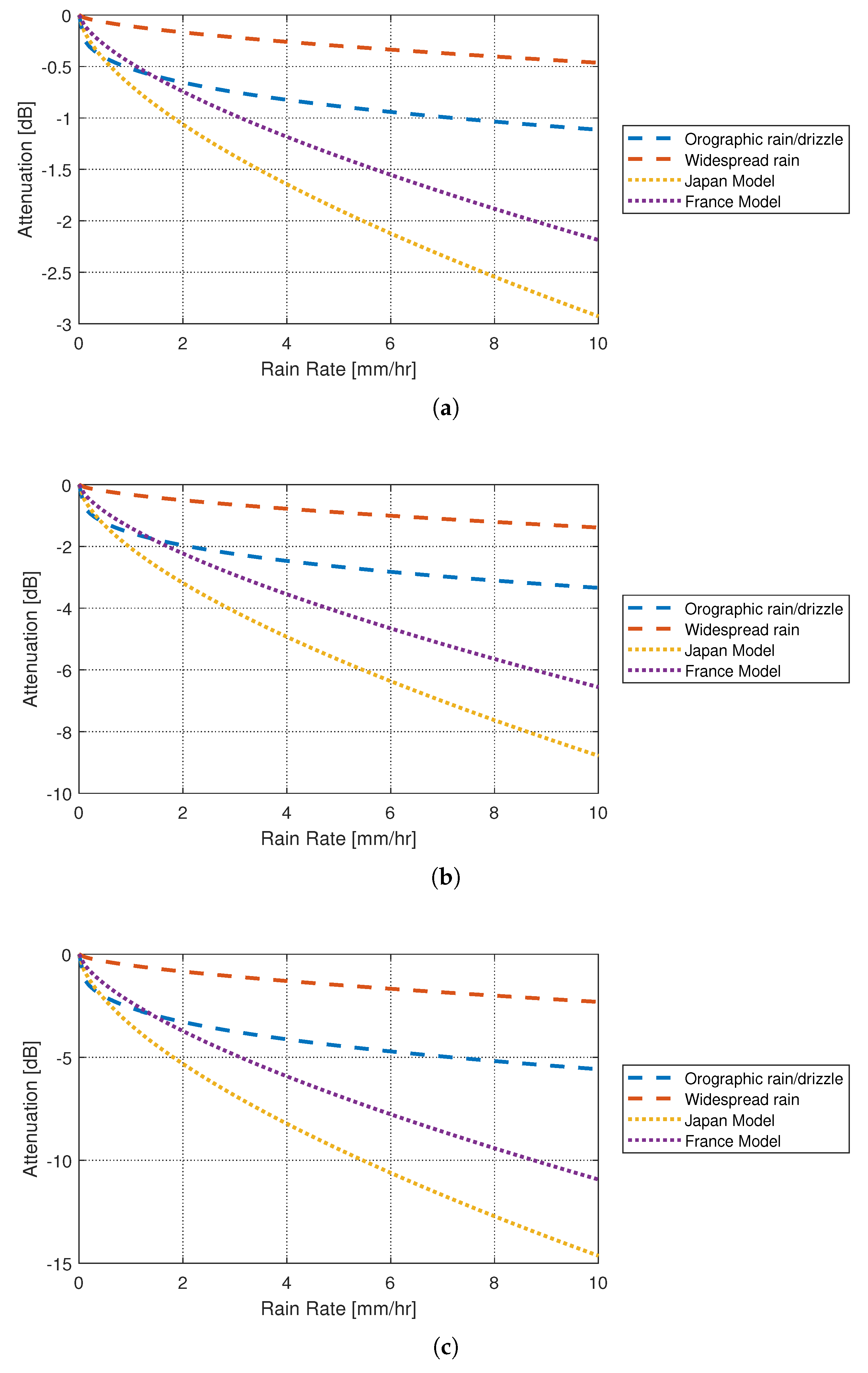
Figure 8.
Effects of atmospheric turbulence.
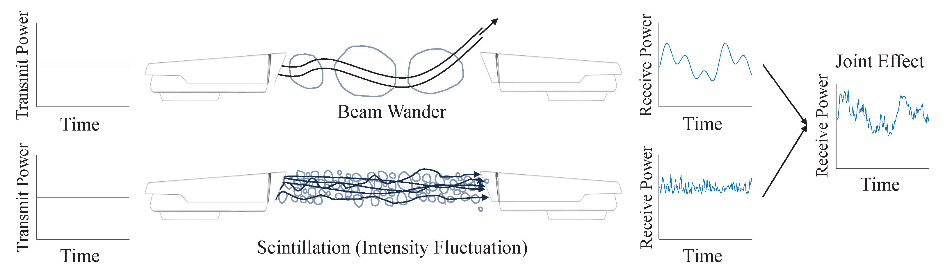
Figure 9.
Losses due to the propagation of FSO signal through a turbulent channel at propagation distance of (a) 0.1 km, (b) 1 km, and (c) 10 km.
Figure 9.
Losses due to the propagation of FSO signal through a turbulent channel at propagation distance of (a) 0.1 km, (b) 1 km, and (c) 10 km.

Figure 10.
Losses due to pointing error.

Figure 11.
Single-layer aerial backhaul in rural areas (adopted from [103]).
Figure 11.
Single-layer aerial backhaul in rural areas (adopted from [103]).
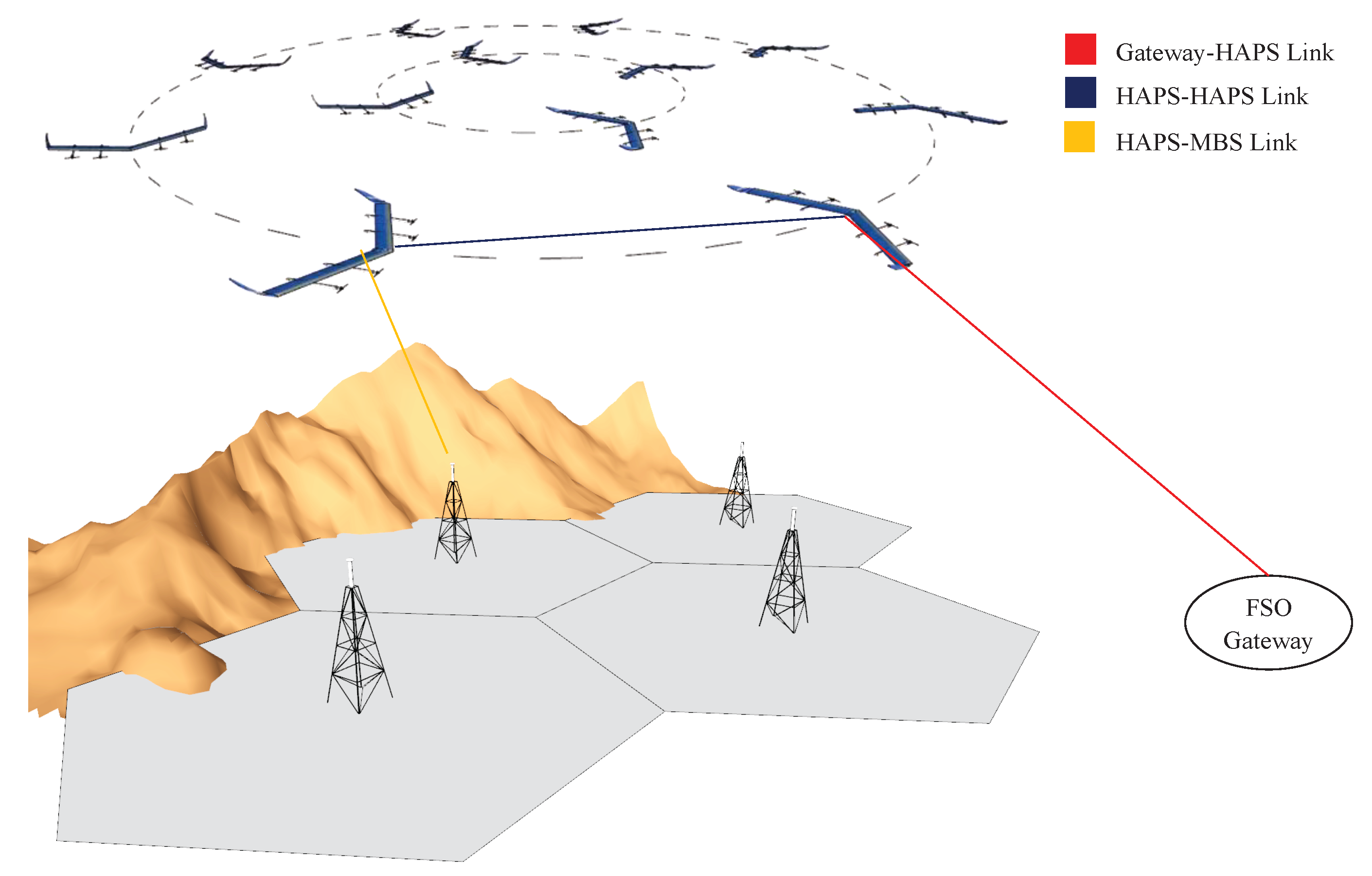
Figure 12.
Multi-layer aerial backhaul in urban areas (adopted from [103]).
Figure 12.
Multi-layer aerial backhaul in urban areas (adopted from [103]).

Figure 13.
Block diagrams for (a) IM/DD and (b) CM/CD.
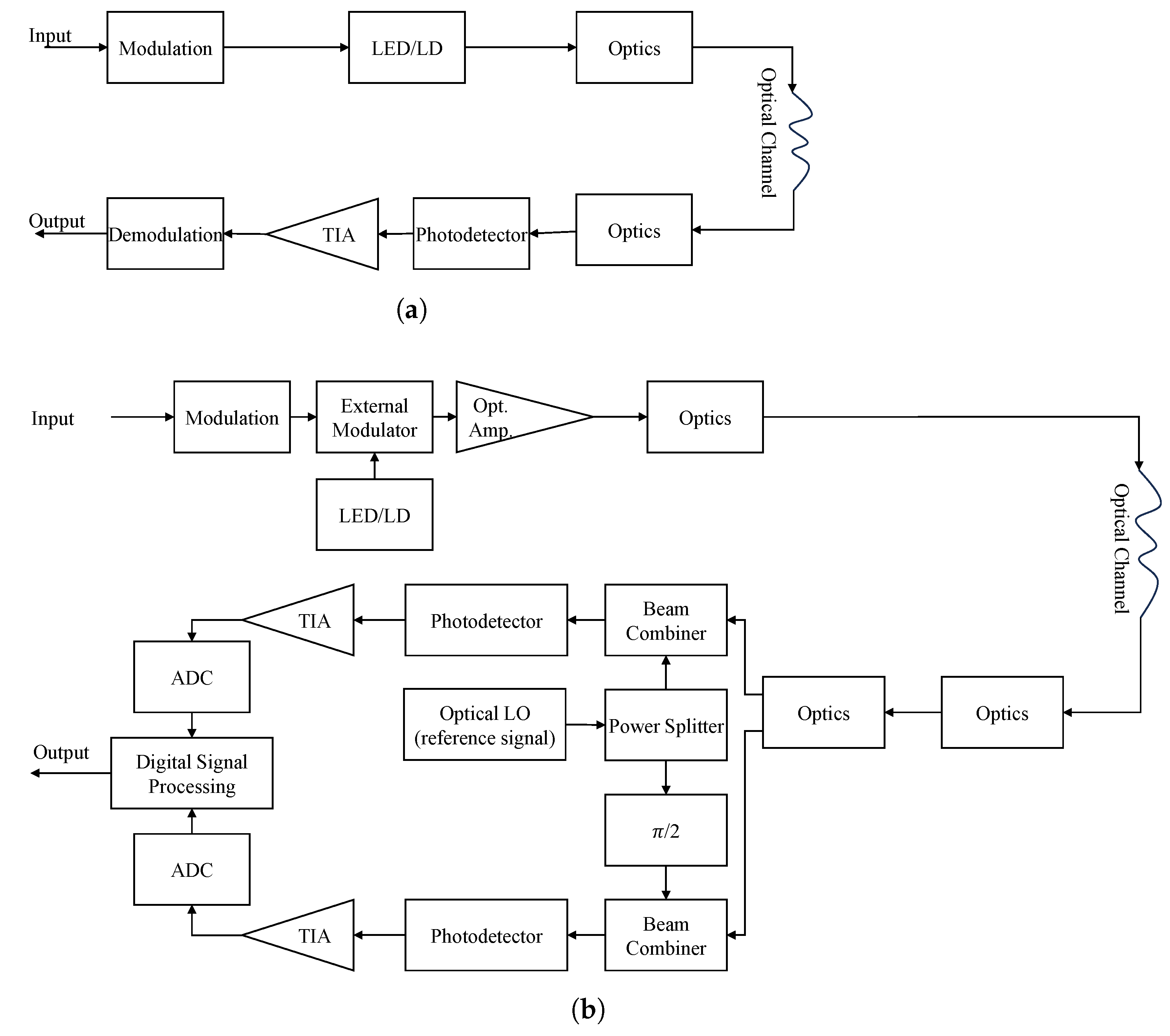
Figure 14.
Laser power beaming for airborne nodes.
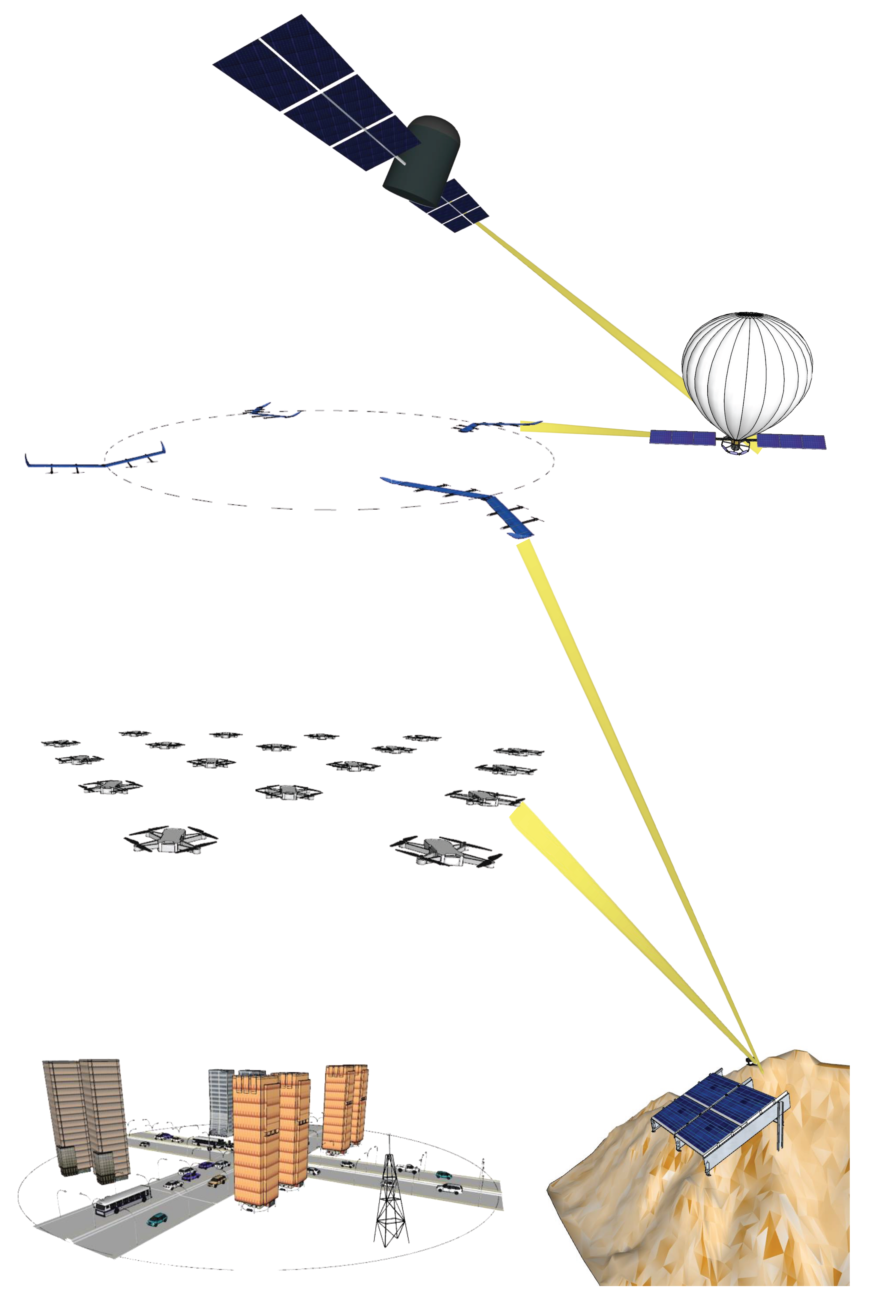

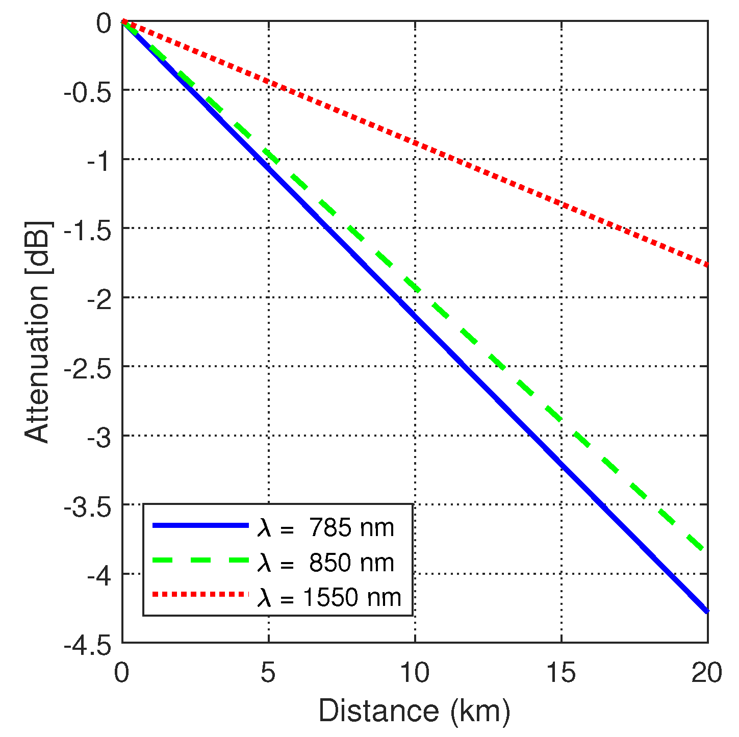
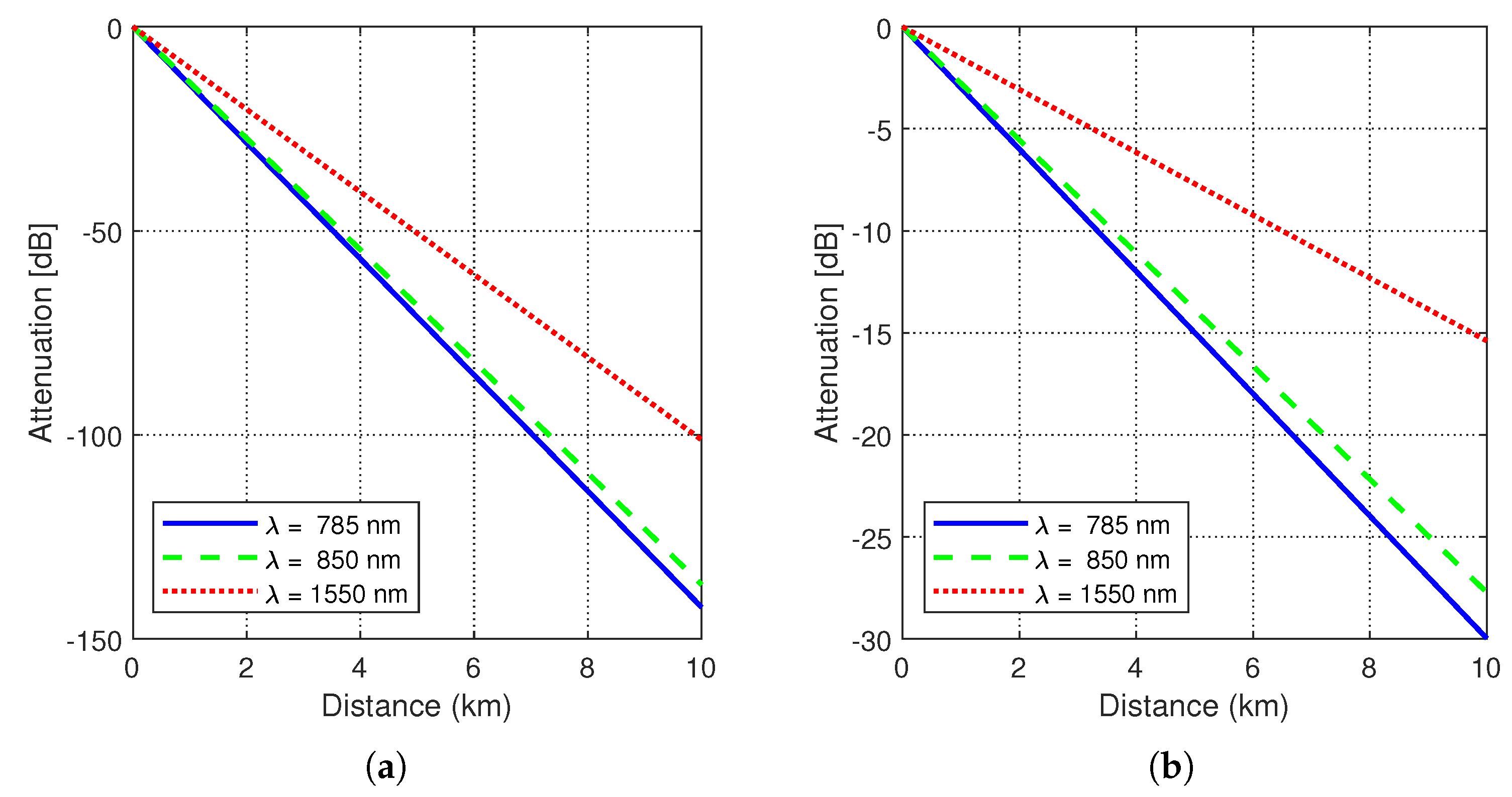
Table 1.
Classification of NTN nodes.
| Node Type | Altitude Range | Description | |
|---|---|---|---|
| GEO |  | Outer Space (36,000 km) | GEO satellites orbit the Earth at an altitude of 35,786 km above the equator [16]. Their orbit matches the Earth’s rotation, resulting in a synchronized orbit. Therefore, they remain fixed relative to a specific location on the Earth’s surface, appearing stationary in the sky. |
| MEO | Outer Space (2000 km to GEO altitude) | While a GEO has a fixed altitude of 35,786 km, MEO satellites can be found at various altitudes within the range from 2000 km to the altitude of a GEO, based on their specific mission and requirements [16]. Most MEO satellites are found at altitudes between 8000 and 20,000 km. The key advantage of placing satellites in MEO is balancing the coverage area and signal delay. | |
| LEO | Outer Space (up to 2000 km) | The altitude of LEO satellites is up to 2000 km above the Earth’s surface [16]. Due to their operational altitude being closer to the Earth, LEO satellites circle the Earth more frequently than satellites in higher orbits. LEO satellites have the advantage of proximity to Earth, enabling rapid data transmission. However, this proximity also means they offer more limited coverage of a specific area compared to satellites in other orbits. | |
| Aerostatic HAPS (balloons, airship) |  | Stratosphere (17–22 km) | Aerostatic HAPSs are lighter-than-air vehicles and take the form of balloons and airships [17]. These make use of a lifting gas (e.g., helium, hydrogen) less dense than the surrounding air to remain airborne. Balloons are characterized by their compact size, lightweight construction, and affordability. Functioning as wind-powered platforms, they utilize wind patterns to determine their path and altitude. Unlike balloons, airships are equipped with a propulsion system for more precise navigation and positioning. Their payload capacity is also much higher. Airships were most commonly used before the 1940s. New generations of solar-powered high-altitude airships have recently been developed. |
| Aerodynamic HAPS |  | Stratosphere (17–22 km) | Aerodynamic HAPSs are heavier than air [17] and rely on the principles of aerodynamics to generate the lift forces necessary for sustained flight. The most common form of aerodynamic HAPS is a fixed-wing aircraft, typically powered by solar panels attached to its wings. |
| Rotary-wing UAV |  | Troposphere (from a few hundred meters up to few kms above the ground) | Rotary-wing UAVs have the capability for hovering and maintaining a semi-steady fixed position. These UAVs have the advantages of vertical takeoff, hovering, and maneuverability. |
| Fixed-wing UAV |  | Troposphere (<17 km) | Fixed-wing UAVs have longer endurance and greater range than rotary-wing UAVs, making them ideal for applications requiring extended flight times and a larger area coverage [18]. They offer stability during level flight and the ability to carry significant payloads compared to rotary-wing UAV’s, such as high-resolution cameras, scientific instruments, and sensors. |
Table 2.
Comparison of satellite and aerial technologies—altitude, latency, coverage, required nodes, applications, advantages, disadvantages, stationary status.
Table 2.
Comparison of satellite and aerial technologies—altitude, latency, coverage, required nodes, applications, advantages, disadvantages, stationary status.
| Technology | GEO | MEO | LEO | HAPS | UAVs |
|---|---|---|---|---|---|
| Altitude | ≈ 35,786 km [60] | ≥2000 km [60] | ≈160–2000 km [60] | ≈17–22 km | ≤17 km |
| Latency | 600–800 ms [61] | 125–250 ms [61] | 30–50 ms [61] | ≤30 ms | ≤30 ms |
| Coverage | Global/Very Large | Global/Very Large | Global/Very Large | Regional/Large | Local |
| Number of Required Nodes |
|
|
|
|
|
| Applications | Broadcasting, Weather monitoring, Communication, GPS | Navigation, Weather forecasting, GPS, and Communication | Earth observation, Remote sensing, GPS, Communication, and Astronomy | Communication, Surveillance, and Monitoring | Surveillance, Monitoring, and wireless access. |
| Advantages |
|
|
|
|
|
| Disadvantages |
|
|
|
|
|
| Flexibility | None | Limited | Limited | High | High |
| General Payload Capacity | High | Moderate | Limited | Limited | Limited |
| Endurance | Years | Years | Years | Several weeks/months | Several hours to Days |
Table 3.
Comparison of RF and FSO technologies for backhauling.
| Comparison Factors | RF | Optical |
|---|---|---|
| Bandwidth | Hundreds of MHz to several GHz [63]. | Tens of GHz per wavelength. |
| Interference | Prone to interference from electromagnetic waves. | Immune to RF interference. |
| Regulatory Requirements | Requires licenses and compliance with regulatory guidelines. | Operates in the unregulated optical spectrum, eliminating the need for spectrum licenses and reducing regulatory constraints. |
| Multipath Interference | Subject to multipath interference due to reflections, diffractions, and scattering. | Highly directional laser beam, resulting in better signal integrity and reliability. |
| Movement-Induced Issues | Less susceptible to pointing errors and movement-induced issues. | Highly susceptible to pointing errors, which can impact signal stability, especially in adverse weather conditions or moving platforms. |
| Security | Vulnerable to eavesdropping and interception. | It offers higher security with narrower beams that are difficult to intercept. |
| Latency | Both RF and optical signals propagate through the Earth’s atmosphere at nearly the same speed, close to the speed of light in a vacuum [64]. | |
| Installation Complexity | Relatively simpler installation. | Installation may be complex, requiring precise alignment and considerations for weather conditions. |
| Cost | Often lower initial setup costs. | May have higher initial setup costs due to specialized equipment, alignment requirements, and tracking systems. |
| Scalability | Easily scalable with additional equipment. | Scalability may be limited by atmospheric conditions and LoS requirements. |
| Data Rate | Typically, lower data rates compared to optical. | Offers higher data rates, especially for point-to-point communication. |
| Reliability | RF technology can be reliable in various environmental conditions. | Weather conditions, such as fog or rain, can affect reliability, leading to signal degradation. |
Table 4.
Models for fog extinction coefficients.
| Models | Wavelength | Visibility |
|---|---|---|
| Kruse Model | 785 and 1550 | 0 m to more than 50 km |
| Kim Model | 785 and 1550 | 0 m to more than 50 km |
| Al-Naboulsi | 400- to 1500 | 50 m to 1000 m |
Table 5.
Rain model parameters.
| Model Name | k | |
|---|---|---|
| Japan | 1.58 | 0.63 |
| France | 1.076 | 0.67 |
| Widespread rain | 0.25 | 0.63 |
| Orographic rain/drizzle | 1.20 | 0.33 |
Table 6.
Pointing errors in HAPS-to-ground and rotary-wing UAV-to-ground FSO Links.
| HAPS-Ground Links | UAV-Ground Links | |
|---|---|---|
| Factors/Reasons |
|
|
| Mitigation techniques |
|
|
Disclaimer/Publisher’s Note: The statements, opinions and data contained in all publications are solely those of the individual author(s) and contributor(s) and not of MDPI and/or the editor(s). MDPI and/or the editor(s) disclaim responsibility for any injury to people or property resulting from any ideas, methods, instructions or products referred to in the content. |
© 2023 by the authors. Licensee MDPI, Basel, Switzerland. This article is an open access article distributed under the terms and conditions of the Creative Commons Attribution (CC BY) license (https://creativecommons.org/licenses/by/4.0/).
Share and Cite
MDPI and ACS Style
Elamassie, M.; Uysal, M. Free Space Optical Communication: An Enabling Backhaul Technology for 6G Non-Terrestrial Networks. Photonics 2023, 10, 1210. https://doi.org/10.3390/photonics10111210
AMA Style
Elamassie M, Uysal M. Free Space Optical Communication: An Enabling Backhaul Technology for 6G Non-Terrestrial Networks. Photonics. 2023; 10(11):1210. https://doi.org/10.3390/photonics10111210
Chicago/Turabian StyleElamassie, Mohammed, and Murat Uysal. 2023. "Free Space Optical Communication: An Enabling Backhaul Technology for 6G Non-Terrestrial Networks" Photonics 10, no. 11: 1210. https://doi.org/10.3390/photonics10111210
Note that from the first issue of 2016, this journal uses article numbers instead of page numbers. See further details here.