Laser Heating Method for an Alkali Metal Atomic Cell with Heat Transfer Enhancement

School of Optical-Electrical and Computer Engineering, University of Shanghai for Science and Technology, Shanghai 200093, China
*
Author to whom correspondence should be addressed.
Photonics 2023, 10(6), 637; https://doi.org/10.3390/photonics10060637
Submission received: 17 April 2023
/
Revised: 27 May 2023
/
Accepted: 29 May 2023
/
Published: 1 June 2023
(This article belongs to the Special Issue Optically Pumped Magnetometer and Its Application)
Abstract
:Alkali metal atomic cells are crucial components of atomic instruments, such as atomic magnetometers, atomic gyroscopes, and atomic clocks. A highly uniform and stable heating structure can ensure the stability of the alkali metal atom density. The vapor cell of an atomic magnetometer that uses laser heating has no magnetic field interference and ease of miniaturization, making it superior to hot air heating and AC electric heating. However, the current laser heating structure suffers from low heating efficiency and uneven temperature distribution inside the vapor cell. In this paper, we designed a non-magnetic heating structure based on the laser heating principle. We studied the temperature distribution of the heating structure using the finite element method (FEM) and analyzed the conversion and transfer of laser energy. We found that the heat conduction between the vapor cell and the heating chips (colored filters) is poor, resulting in uneven temperature distribution and low heating efficiency in the vapor cell. Therefore, the addition of graphite film to the four surfaces of the vapor cell was an important improvement. This addition helped to balance the temperature distribution and improve the conduction efficiency of the heating structure. It was measured that the power of the heating laser remained unchanged. After the addition of the graphite film, the temperature difference coefficient (CVT) used to evaluate the internal temperature uniformity of the vapor cell was reduced from 0.1308 to 0.0426. This research paper is crucial for improving the heating efficiency of the non-magnetic heating structure and the temperature uniformity of the vapor cell.
1. Introduction
With the rapid development of atomic operation technology and optical technology, the ultra-sensitive magnetic field sensor based on SERF (Spin-Exchange Relaxation-Free) effect, which uses atoms as sensitive components, has been widely used in various fields, such as medicine, national defense, and aerospace. Examples of their applications include magnetoencephalography (MEG) for brain imaging [1,2,3,4], magnetocardiography (MCG) for heart imaging [5,6,7], and geological dating investigations [8]. The world’s most sensitive SERF atomic magnetometer has a sensitivity of 160 aT/Hz1/2, which is also the record for magnetic field measurements [9]. In high-sensitivity magnetometers, a drop of alkali metal in the vapor cell needs to be heated into high-density vapor, and the saturation vapor pressure of alkali metal atoms directly affects the sensitivity of the SERF atomic magnetometer. The spatial distribution of alkali vapor density in a large vapor cell has a direct impact on the processing of measurement signals for multichannel magnetic fields. The density distribution depends on the spatial temperature distribution [10]. Therefore, it is essential to optimize the heating method and structure of the vapor cell to improve its temperature stability and uniformity. Additionally, any additional magnetic noise should be avoided during the heating process [11].
There are three common heating methods: electric heating [12,13,14,15,16], flow hot air heating [17,18], and laser heating [19,20,21,22,23,24,25]. Although flow hot air heating can ensure that no additional magnetic noise is introduced, its heating efficiency is low, and the overall structure is too large to be integrated. Electric heating can use a lock-in amplifier to filter out additional magnetic noise in the signal, but the working frequency must remove the heating current frequency, which limits the measurement range of the atomic magnetometer. More importantly, this method cannot completely filter out residual magnetic noise. Although intermittent electric heating can completely avoid additional magnetic noise, the atomic magnetometer does not work during the heating process, and it cannot measure the continuous changes in the magnetic field, directly leading to a decrease in the sensitivity of the atomic magnetometer. In contrast, laser heating is a good option compared to other heating technologies because it does not generate additional magnetic noise. Furthermore, as atomic magnetometers continue to miniaturize and integrate, the energy required to heat chip-level atomic cells to the target temperature is very low. The continuous optimization and updating of the laser heating structure also promote laser heating as the mainstream heating method for alkali metal cells in the future. Therefore, the non-magnetic heating method chosen in this study is laser heating. Preusser et al. [23] used a 915 nm semiconductor laser to directly heat the vapor cell, which was heated to 97 °C with a required laser power of 200 mW. The laser energy cannot be completely absorbed by the vapor cell, and the heating efficiency is limited. Mhaskar et al. [24] and Sheng [25] installed colored filters on both sides of the vapor cell to improve the laser absorption efficiency, but there is still residual energy that has not been utilized. In Sheng’s study, two 1550 nm laser beams were used simultaneously to heat the vapor cell, which made the heating structure more complex. Therefore, improving the laser heating efficiency and the spatial uniformity of the temperature inside the vapor cell while simplifying the heating structure is also the key to improving laser heating technology.
In this paper, we study a heating structure for a cell that utilizes laser heating technology, which is to improve the heating efficiency and temperature uniformity of the vapor cell. First, a finite element (FEM) model is established to study the internal temperature of the vapor cell and analyze the laser energy conversion and transfer. To solve the problems of low heating efficiency and uneven temperature distribution inside the vapor cell caused by the poor thermal conductivity of the vapor cell and the heating chips (colored filters), we added a graphite film to the heating structure. To validate the proposed method, the operating power of the heating laser is kept constant, and graphite films of different sizes are added to the heating structure. This is performed to measure the temperature variation inside the vapor cell. The CVT and the temperature error distribution plots of the vapor cell are used to characterize the uniformity of the temperature distribution inside the vapor cell.
2. Analysis and Simulation Methods
2.1. Heat Transfer Analysis
The heating process involves three types of heat transfer: thermal radiation, thermal convection, and thermal conduction. The heating chips convert laser energy to thermal energy and transfer it evenly to the outer wall of the vapor cell through heat conduction. The outer wall of the vapor cell then radiates heat to the gas inside the vapor cell. Simultaneously, the colored filters and the vapor cell emit thermal energy to the surrounding environment through thermal radiation. Eventually, the entire system reaches a dynamic equilibrium state, where heat conduction can be expressed by Fourier’s law of heat conduction as follows [26]:
In Equation (1), is temperature, is time, is the density of the object, is constant pressure heat capacity, is the thermal conductivity. The left side of the equation shows the rate of heat transfer, so heat transfer is only affected by the material properties of the object. The heat radiation can be expressed by the Stefan–Boltzmann equation as follows:
where is the heat flow rate, is the rate of radiation, is Stefan–Boltzmann constant, is the area of radiation surface, is temperature of the vapor cell’s wall, and is the temperature of the alkali metal gas in the vapor cell. The heat convection can be expressed by Newton cooling equation as follows:
where is the heat transfer coefficient, is the area of the radiating surface, is the temperature of solid surface, and is the fluid temperature around the solid. When the system finally reaches dynamic stability, the thermal balance equation is obtained as follows:
where is the total heat input; is the velocity field in the fluid; is the Nabla operator, and it is defined as a differential operator; it also has vector form, so is the changes of temperature in all directions in space; and is the density of the object. The heating chips and the vapor cell are closely bonded and placed in the insulating layer. When the system reaches a stable state, the primary heat transfer mode is conduction, and convection and radiation can be disregarded. In this study, both the vapor cell and the heating chips are made of quartz glass, which has low thermal conductivity and high thermal capacity at constant pressure. Therefore, the thermal conductivity of the system is poor. To improve the thermal conductivity of the system, the graphene thin layers are added to the heating structure. As a material with high thermal conductivity, graphite sheets have a lamellar structure with anisotropy [27,28,29]. The thermal conductivity is high along the lamellar direction and low in the vertical direction.
2.2. Finite Element Analysis
Based on the COMSOL Multiphysics simulation software, the temperature distribution of a cell heated by a pair of heating chips on the X-axis is studied using the finite element analysis method. The required physical field is heat transfer in solid. The simulation process consists of four steps. First, the heating structure model is built, including heating chips, the vapor cell, and graphite films. Second, material properties are set, and physical fields are added for solid and fluid heat transfer. The heating chip heats the vapor cell by absorbing the energy of the laser, so the boundary of the heating chip is set as the heat source in the way of heat flux. The energy of the heating laser is a continuous laser with a Gaussian spatial distribution (GSD). The laser source is defined as follows [30]:
Q is the heat produced by the laser; is the energy density of the laser, expressed as ; is the working power of the laser; and is the area of the laser spot. Gaussian spatial distribution (GSD) is represented by Equation (6):
is the radius of the laser spot. is the distance to the center of the laser spot, which is expressed as ; represents the coordinates of the center point of the laser source; the radius of the laser spot is set to 4 mm; and the initial temperature of the environment is set to 20 °C. In order to improve the calculation precision, the whole heating model is partitioned by grid. The sizes of the grid units of the heating chips and the vapor cell are, respectively, set to fine and extremely fine. Finally, the transient temperature of the heating structure is analyzed, and the temperature distribution when temperature of the vapor cell reaches dynamic stability is analyzed.
3. Experimental Setup
The rubidium SERF magnetometer comprise a cell, a pump laser, a detection laser, a magnetically shielded barrel, and a non-magnetic heating structure. The non-magnetic heating structure is responsible for heating the rubidium vapor to operational temperature without creating any magnetic noise during the heating process. In this paper, we selected a laser to heat the rubidium gas cell. As illustrated in Figure 1, the heating structure consists of the following components: a 1550 nm heating laser, two heating chips (colored filters), a temperature sensor (PT100), a cell, an insulation layer, a graphite film, and a thermal imaging camera with a real-time 160 × 120-pixel thermal map.
In this experiment, colored filters from SCHOTT were utilized as heating chips to absorb laser energy in the 1550 nm wavelength range. The incident and exit window filters for the heating laser were 1 mm UG-5 and 3 mm RG-9, respectively; the incident optical power absorbed by the two filters was 56.3% and 100%, allowing each filter to absorb approximately equal amounts of heating laser energy; and the converted heat was then used to heat the vapor cell. The temperature and temperature distribution of the vapor cell were measured via a temperature sensor (PT100) and thermal imager, respectively, the rubidium atomic vapor and buffer gas are enclosed in a 20 mm × 20 mm × 20 mm cubic alkali metal cell. An insulating layer is incorporated to reduce heat loss and enhance heat transfer efficiency; the cube-shaped insulating layer with a side length of 40 mm is made of polyimide foam, which has a thermal conductivity of 0.035 W/(m·K). Two cylindrical holes with a diameter of 10 mm intersect with the cube, allowing for the passage of lasers that irradiate the vapor cell.
After conducting the experiment, it was found that the thermal conductivity of the vapor cell and heating was poor. Therefore, a graphite film is added to the heating structure as a high thermal conductive layer to balance the temperature distribution and improve the conduction efficiency. The thickness of the graphite film is 0.2 mm. The thermal conductivity along the fiber axis is 800 W/(m·K), and the thermal conductivity perpendicular to the fiber axis is 10 W/(m·K). The graphene thin layer, as shown in Figure 2, is a square sheet of 20 mm × 80 mm in size. This sheet contains two circular holes of 10 mm diameter each for light passage and one circular hole of 6 mm diameter for passage through the vapor cell shank.
4. Results and Discussion
4.1. Simulated Results
During the simulation process, it was observed that the thermal conductivity of the heating chips and the vapor cell was extremely low. As a result, a significant amount of heat was concentrated in the center of the heating chips, and it is not transferred to the vapor cell, which led to a high level of thermal loss and low internal temperature uniformity in the vapor cell. To address this issue, the thin layer structure was introduced for solid heat transfer. A graphite film was added to the contact surface of the vapor cell and the heating chips to increase the thermal conductivity of the heating structure. The layer thickness was set to 0.2 mm for optimal results, and the thermal conductivity along the fiber direction of the graphite film was 800 W/(m·K), whereas that perpendicular to the fiber axis was 10 W/(m·K). Figure 3 displays the distribution of isotherms on the heating chips’ surface with or without the addition of a graphite film. The temperature distribution of the heating chips with the graphite film is more uniform compared to the one without the graphite film under the same power of the heating laser.
The ambient temperature is 20 °C, the laser power is set to 2.4 W, and the diameter of the heated laser spot is 8 mm. Heating time can be reduced via a pair of heating chips to heat the vapor cell simultaneously. The temperature gradient of the vapor cell is smaller when a heater is placed in each of the two windows of the heating laser compared to placing a heater in only one window. Using the finite element method to simulate the heat transfer of the heating structure with added graphite film, Figure 4a shows the temperature distribution of the two heating chips when heating the vapor cell.
We define the center point of the vapor cell as A, and the space coordinates of point A is (0,0,10), and two heating chips are distributed at 10 mm and −10 mm of the x axis. Figure 4b shows the temperature distribution of the heating structure on the XAY, YAZ, and XAZ planes. L1, L2, and L3 represent three straight lines passing through the x, y, and z axes of the central point inside the vapor cell. In contrast to the temperature graph in Figure 4c, the temperature gradient in the direction of the X-axis is larger. This is because the perforations of the insulating layer are oriented in the direction of both the x-axis and the y-axis, and the two heating chips are also located in the direction of the x-axis. Furthermore, the heating chip located in the incident window of the heating laser absorbed 12.6% more laser energy than the heating chip located in the outgoing window of the heating laser. This is the main reason for the large temperature gradient along the X-axis. The smaller temperature gradient in the Y-axis direction is due to the smaller aperture and less thermal exchange between the vapor cell and the external environment. In the Z-axis direction, the vapor cell’s temperature gradient is the smallest, and the outer wall temperature of the vapor cell is close to the interior temperature. Therefore, to reduce the temperature measurement error, the temperature sensor (PT100) can be placed in the upper shell center of the vapor cell to measure its temperature.
4.2. Experiments
To study the uniformity of the vapor cell under laser heating, we measured the internal temperature using a temperature sensor (PT100) and a thermal imager. The temperature sensor (PT100) was attached to the upper center of the vapor cell, and the measurement results are shown in Figure 5.
When graphite film is added to the four sides of the vapor cell, the operating power of the 1550 nm heating laser is 2.4 W. It can be seen from Figure 5 that when the power of the heating laser is 2.4 W, the simulated interior temperature of the vapor cell is 120 °C, while the experimental temperature of the vapor cell is 118 °C. This is because the thermal insulation structure cannot completely eliminate the vapor cell and the outside thermal radiation, resulting in heat loss of the vapor cell, so there is a deviation between theoretical simulation and experimental data.
Figure 6 is a thermal image of the internal temperature radiation of the vapor cell with the Y-axis facing. This is when the graphite film is not added to the surface of the vapor cell, and the graphite film with different sizes is added.
From Figure 6, it is evident that the temperature near the laser incident window in the vapor cell is the highest. This is because the heating chip located in the exit window absorbed too much laser energy, resulting in the two colored filters absorbing different amounts of laser energy. Therefore, one can select either a thin heating chip or a heating chip with a low absorption rate to the heating laser. Figure 6a shows the temperature radiography of the vapor cell without the addition of a graphite film. The material of the vapor cell and the heating chips is quartz glass, which has a poor thermal conductivity at 1.4 W/(m·K). This leads to a significant accumulation of heat in the incident window of the laser. The thermal energy inside the vapor cell comes from the radiant heat of the vapor cell wall. However, there is a shank at the bottom of the vapor cell, which increases the radiant distance at the bottom of the vapor cell. As a result, the temperature of the bottom side is lower than the upper side. In the experiment, when the laser power reached 600 mW, the UG-5 heating chip broke due to the large difference in temperature between the center and the surrounding areas. In Figure 6b, the graphite film was pasted on the two surfaces of the vapor cell that were in contact with the heating chips, which obviously improved the uniformity of the temperature distribution of the incident window. However, the temperature of the exit window remained low, which was due to the poor thermal conductivity of the vapor cell. In Figure 6c, we have pasted graphite films on the upper surface of the vapor cell to increase heat transfer along the X-axis. As can be seen from the figure, the heat from the incident window is transferred to the exit window by the graphite film, improving the temperature uniformity of the upper part of the vapor cell.
In order to improve the temperature uniformity of the vapor cell, the graphite film covers the upper and lower top surfaces of the vapor cell, the incident light window, and the outgoing light window at the same time. Under the same heating condition, the thermal radiation Figure 6d is obtained. By comparing the temperature radiation in Figure 6, it can be concluded that the graphite film improves the thermal conductivity of the system and makes the temperature distribution of the vapor cell more uniform. However, the thermal radiation between the vapor cell and the outside also increased, and the overall temperature of the vapor cell decreased.
Converting the temperature radiography of the vapor cell in Figure 6 to the temperature error analysis diagram shown in Figure 7 in order to visualize the temperature uniformity of the vapor cell.
It can be seen from Figure 7 that the graphite film can improve the thermal conductivity of the heating structure and balance the temperature distribution of the vapor cell. However, due to the heating chip of the incident window absorbing too much laser energy, the temperature of the incident window is higher. The reason why the two surfaces in the Y-axis direction of the vapor cell are not chosen to stick graphite films is to capture the temperature radiation pattern of the vapor cell.
Figure 6 and Figure 7 show the influence of graphite film on the temperature uniformity of the vapor cell. Finally, we introduce the temperature difference coefficient to evaluate the temperature uniformity of the vapor cell.
The expression for the CVT is as follows:
where is the average temperature, and is the unbiased variance of the temperature. denotes , where is the temperature of each plane point, and S is the surface area; is denoted by . According to Equation (7), the smaller the CVT is, the more uniform the temperature distribution is. The measured temperature radiography was converted into a temperature matrix to obtain the CVT values, and the different CVTs were obtained, as shown in Table 1.
From Table 1, as the size of the graphite film increases, the calculated CVT of the vapor cell decreases, and the temperature uniformity of the vapor cell improves. Therefore, the temperature uniformity of the heating structure is greatly improved by adding graphite films.
5. Conclusions
In this paper, a vapor cell heating structure based on laser heating technology was constructed, and the spatial distribution of temperature was optimized via graphite films. By constructing the finite element model, the numerical analysis of the thermal transfer in the heating system shows that the uniformity of the temperature in the vapor cell is limited because the heat transfer is poor between the vapor cell and the heating chips. The laser power is constant, and the inner temperature CVT of the vapor cell decreased by 67% after adding graphite film on the four sides of the vapor cell, so the structure of graphite film can efficiently improve the temperature distribution homogeneity in the vapor cell. In the next step, we will study the action mechanism between the temperature homogeneity and the magnetometer output signal.
Author Contributions
Conceptualization, Y.L. and G.Z.; methodology, G.Z.; software, Y.L.; validation, Y.L., G.Z. and S.T.; formal analysis, Y.L.; investigation, G.Z.; resources, X.G.; data curation, Y.L.; writing—original draft preparation, X.L.; writing—review and editing, G.Z.; visualization, S.T.; supervision, S.T.; project administration, X.D.; funding acquisition, X.G. All authors have read and agreed to the published version of the manuscript.
Funding
This research was funded by the National Natural Science Foundation of China (NSFC), grant number 62005167.
Institutional Review Board Statement
Not applicable.
Informed Consent Statement
Not applicable.
Data Availability Statement
Not applicable.
Conflicts of Interest
The authors declare no conflict of interest.
References
- Boto, E.; Meyer, S.S.; Shah, V.; Alem, O.; Knappe, S.; Kruger, P.; Fromhold, T.M.; Lim, M.; Glover, P.M.; Morris, P.G.; et al. A new generation of magnetoencephalography: Room temperature measurements using optically-pumped magnetometers. Neuroimage 2017, 149, 404–414. [Google Scholar] [CrossRef]
- Boto, E.; Holmes, N.; Leggett, J.; Roberts, G.; Shah, V.; Meyer, S.S.; Munoz, L.D.; Mullinger, K.J.; Tierney, T.M.; Bestmann, S.; et al. Moving magnetoencephalography towards real-world applications with a wearable system. Nature 2018, 555, 657–661. [Google Scholar] [CrossRef] [PubMed]
- Zhang, G.Y.; Huang, S.J.; Xu, F.X.; Hu, Z.H.; Lin, Q. Multi-channel spin exchange relaxation free magnetometer towards two-dimensional vector magnetoencephalography. Opt. Express 2019, 27, 597–607. [Google Scholar] [CrossRef]
- Hill, R.M.; Boto, E.; Holmes, N.; Hartley, C.; Seedat, Z.A.; Leggett, J.; Roberts, G.; Shah, V.; Tierney, T.M.; Woolrich, M.W.; et al. A tool for functional brain imaging with lifespan compliance. Nat. Commun. 2019, 10, 4785. [Google Scholar] [CrossRef]
- Wyllie, R.; Kauer, M.; Smetana, G.S.; Wakai, R.T.; Walker, T.G. Magnetocardiography with a modular spin-exchange relaxation-free atomic magnetometer array. Phys. Med. Biol. 2012, 57, 2619. [Google Scholar] [CrossRef]
- Alem, O.; Sander, T.H.; Mhaskar, R.; LeBlanc, J.; Eswaran, H.; Steinhoff, U.; Okada, Y.; Kitching, J.; Trahms, L.; Knappe, S. Fetal magnetocardiography measurements with an array of microfabricated optically pumped magnetometers. Phys. Med. Biol. 2015, 60, 4797–4811. [Google Scholar] [CrossRef]
- Jensen, K.; Skarsfeldt, M.A.; Staerkind, H.; Arnbak, J.; Balabas, M.V.; Olesen, S.P.; Bentzen, B.H.; Polzik, E.S. Magnetocardiography on an isolated animal heart with a room-temperature optically pumped magnetometer. Sci. Rep. 2018, 8, 16218. [Google Scholar] [CrossRef]
- Perry, A.R.; Bulatowicz, M.D.; Larsen, M.; Walker, T.G.; Wyllie, R. All-optical intrinsic atomic gradiometer with sub-20 fT/cm/root Hz sensitivity in a 22 mu T earth-scale magnetic field. Opt. Express 2020, 28, 36696–36705. [Google Scholar] [CrossRef]
- Dang, H.B.; Maloof, A.C.; Romalis, M.V. Ultrahigh sensitivity magnetic field and magnetization measurements with an atomic magnetometer. Appl. Phys. Lett. 2010, 97, 151110. [Google Scholar] [CrossRef]
- Ito, Y.; Sato, D.; Kamada, K.; Kobayashi, T. Optimal densities of alkali metal atoms in an optically pumped K-Rb hybrid atomic magnetometer considering the spatial distribution of spin polarization. Opt. Express 2016, 24, 15391–15402. [Google Scholar] [CrossRef] [PubMed]
- Huang, Q.; Xiang, K.; Huang, Z.J.; Sun, W.M.; Zhang, J.H. A non-magnetic temperature controlling system applied in atomic magnetometer. Adv. Mat. Res. 2013, 760–762, 896–900. [Google Scholar] [CrossRef]
- Liu, G.B.; Li, X.F.; Sun, X.P.; Feng, J.W.; Ye, C.H.; Zhou, X. Ultralow field NMR spectrometer with an atomic magnetometer near room temperature. J. Magn. Reson. 2013, 237, 158–163. [Google Scholar] [CrossRef] [PubMed]
- Jiang, Q.Y.; Luo, H.; Zhan, X.; Zhang, Y.; Yang, K.Y.; Wang, Z.G. Avoiding the impact of the heater-induced longitudinal field on atomic magnetometers. J. Appl. Phys. 2018, 124, 244501. [Google Scholar] [CrossRef]
- Liang, X.Y.; Liu, Z.C.; Die, H.; Wu, W.F.; Jia, Y.C.; Fang, J.C. MEMS Non-Magnetic Electric Heating Chip for Spin-Exchange-Relaxation-Free (SERF) Magnetometer. IEEE Access 2019, 7, 88461–88471. [Google Scholar]
- Lu, J.X.; Wang, J.; Yang, K.; Zhao, J.P.; Quan, W.; Han, B.C.; Ding, M. In-Situ Measurement of Electrical-Heating-Induced Magnetic Field for an Atomic Magnetometer. Sensors 2020, 20, 1826. [Google Scholar] [CrossRef]
- Schwindt, P.D.D.; Lindseth, B.; Knappe, S.; Shah, V.; Kitching, J.; Liew, L.A. Chip-scale atomic magnetometer with improved sensitivity by use of the M-x technique. Appl. Phys. Lett. 2007, 90, 081102. [Google Scholar] [CrossRef]
- Allred, J.C.; Lyman, R.N.; Kornack, T.W.; Romalis, M.V. High-sensitivity atomic magnetometer unaffected by spin-exchange relaxation. Phys. Rev. Lett. 2002, 89, 130801. [Google Scholar] [CrossRef]
- Kominis, I.K.; Kornack, T.W.; Allred, J.C.; Romalis, M.V. A subfemtotesla multichannel atomic magnetometer. Nature 2003, 422, 596–599. [Google Scholar] [CrossRef] [PubMed]
- Preusser, J.; Gerginov, V.; Knappe, S.; Kitching, J. A microfabricated photonic magnetometer. In Proceedings of the 2008 IEEE Sensors, Lecce, Italy, 26–29 October 2008; pp. 344–346. [Google Scholar]
- Alem, O.; Mhaskar, R.; Jimenez-Martinez, R.; Sheng, D.; LeBlanc, J.; Trahms, L.; Sander, T.; Kitching, J.; Knappe, S. Magnetic field imaging with microfabricated optically-pumped magnetometers. Opt. Express 2017, 25, 7849–7858. [Google Scholar] [CrossRef]
- Oelsner, G.; Schultze, V.; Ijsselsteijn, R.; Wittkamper, F.; Stolz, R. Sources of heading errors in optically pumped magnetometers operated in the Earth’s magnetic field. Phys. Rev. A 2019, 99, 013420. [Google Scholar] [CrossRef]
- Savukov, I.; Boshier, M.G. A High-Sensitivity Tunable Two-Beam Fiber-Coupled High-Density Magnetometer with Laser Heating. Sensors 2016, 16, 1691. [Google Scholar] [CrossRef] [PubMed]
- Preusser, J.; Knappe, S.; Kitching, J.; Gerginov, V. A microfabricated photonic magnetometer. In Proceedings of the 2009 Joint Meeting of the European Frequency and Time Forum and the IEEE International Frequency Control Symposium, VOLS 1 and 2, Besancon, France, 20–24 April 2009; pp. 1180–1182. [Google Scholar]
- Mhaskar, R.; Knappe, S.; Kitching, J. A low-power, high-sensitivity micromachined optical magnetometer. Appl. Phys. Lett. 2012, 101, 241105. [Google Scholar] [CrossRef]
- Sheng, D.; Perry, A.R.; Krzyzewski, S.P.; Geller, S.; Kitching, J.; Knappe, S. A microfabricated optically-pumped magnetic gradiometer. Appl. Phys. Lett. 2017, 110, 031106. [Google Scholar] [CrossRef]
- Puri, P.; Jordan, P.M. Wave structure in Stokes’ second problem for a dipolar fluid with nonclassical heat conduction. Acta Mech. 1999, 133, 145–160. [Google Scholar] [CrossRef]
- Nika, D.L.; Balandin, A.A. Phonons and thermal transport in graphene and graphene-based materials. Rep. Prog. Phys. 2017, 80, 036502. [Google Scholar] [CrossRef]
- Cao, H.Y.; Guo, Z.X.; Xiang, H.J.; Gong, X.G. Layer and size dependence of thermal conductivity in multilayer graphene nanoribbons. Phys. Lett. A 2012, 376, 525–528. [Google Scholar] [CrossRef]
- Gill-Comeau, M.; Lewis, L.J. Heat conductivity in graphene and related materials: A time-domain modal analysis. Phys. Rev. B 2015, 92, 195404. [Google Scholar] [CrossRef]
- Vora, H.D.; Santhanakrishnan, S.; Harimkar, S.P.; Boetcher, S.K.S.; Dahotre, N.B. One-dimensional multipulse laser machining of structural alumina: Evolution of surface topography. Int. J. Adv. Manuf. Tech. 2013, 68, 69–83. [Google Scholar] [CrossRef]
Figure 1.
Non-magnetic laser heating structure.

Figure 2.
The core part of the heating structure.

Figure 3.
Graphite film reduces the temperature gradient on the surface of the heating chip. (a) The distribution of isotherms of the heating chip without adding a graphite film; (b) The distribution of isotherms of the heating chip with adding a graphite film.
Figure 3.
Graphite film reduces the temperature gradient on the surface of the heating chip. (a) The distribution of isotherms of the heating chip without adding a graphite film; (b) The distribution of isotherms of the heating chip with adding a graphite film.
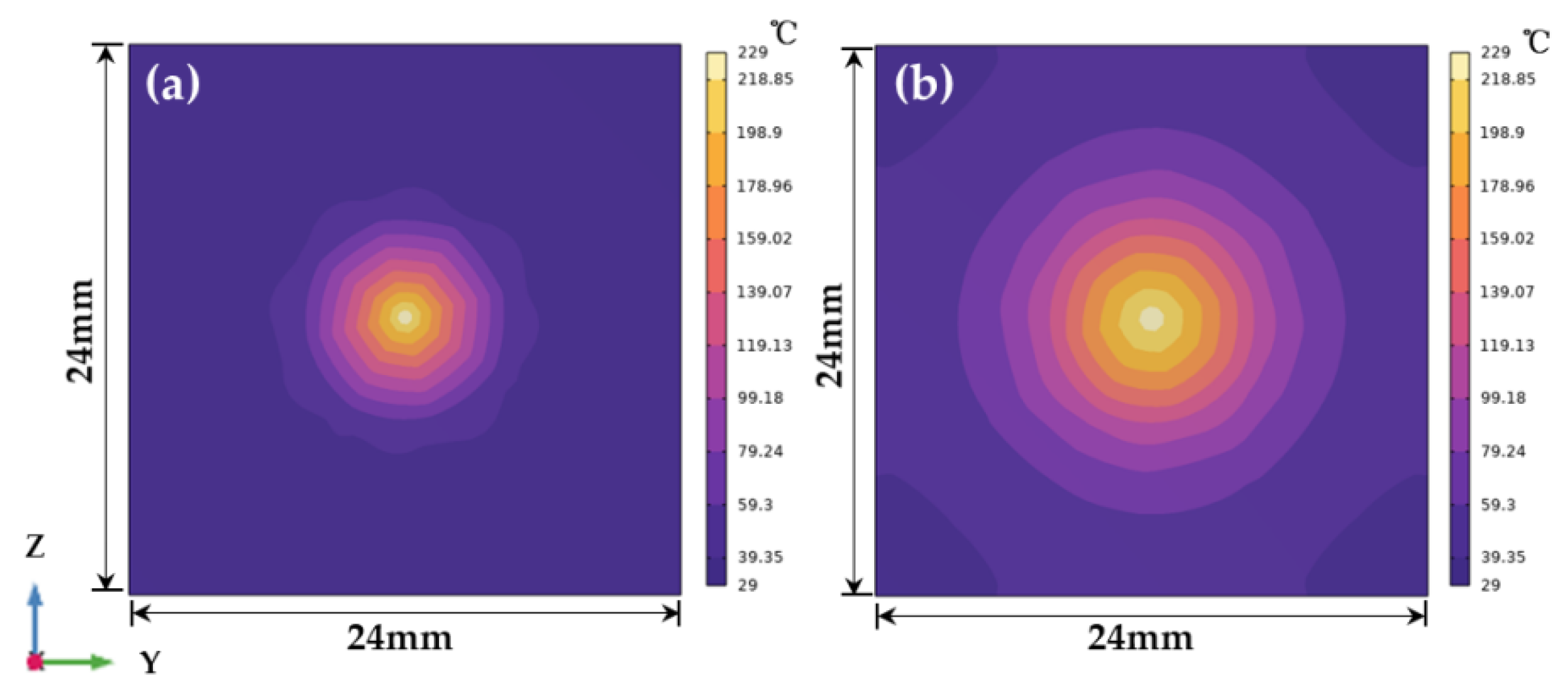
Figure 4.
(a) The temperature distribution diagram of the heating structure when the temperature in the vapor cell is around 120 °C; (b) Temperature distribution on the XAY, YAZ, and XAZ planes; (c) Taking the center of the vapor cell as the coordinate origin, the temperature curve along the three axes.
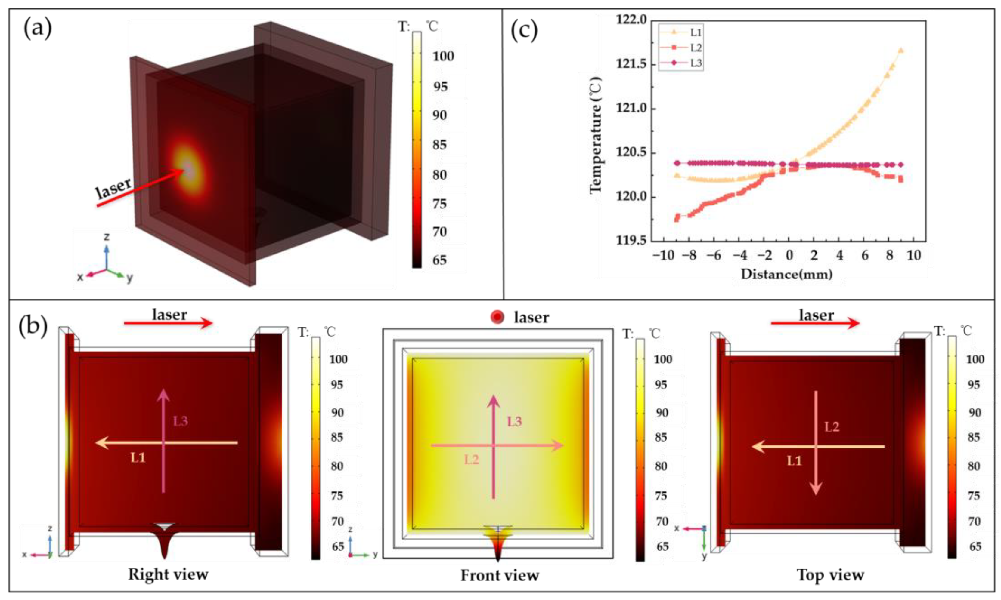
Figure 5.
Simulated (red) and experimental (black) temperature curves of the vapor cell were measured.
Figure 5.
Simulated (red) and experimental (black) temperature curves of the vapor cell were measured.
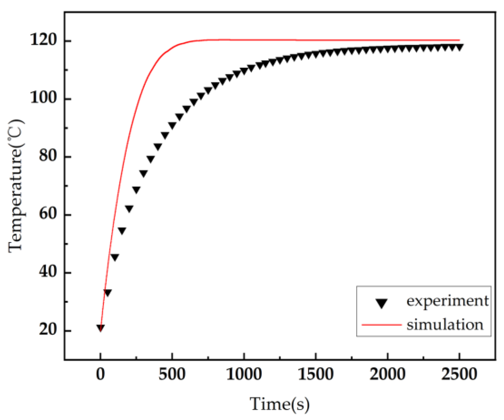
Figure 6.
Temperature radiography was performed on the vapor cell with different sizes of graphite films added. (a) the vapor cell without any graphite films; (b) the vapor cell with graphite films on two surfaces; (c) the vapor cell with graphite films on three surfaces; (d) the vapor cell with graphite films on four surfaces.
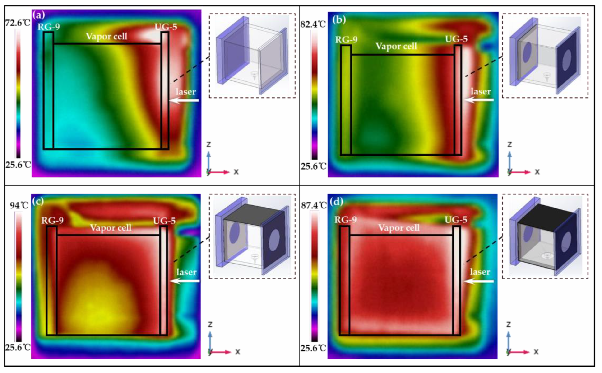
Figure 7.
Temperature error profiles were measured for the vapor cell with different graphite films being added. (a) The vapor cell without graphite films; (b) the vapor cell with graphite film added to two surfaces; (c) the vapor cell with graphite films added to three surfaces; (d) the vapor cell with graphite films added to four surfaces.


Table 1.
The CVT value of the vapor cell changes when graphite films of different sizes are applied to the outer wall of the vapor cell.
Table 1.
The CVT value of the vapor cell changes when graphite films of different sizes are applied to the outer wall of the vapor cell.
| Size | CVT |
|---|---|
| 0 | 0.1308 |
| 20 mm × 20 mm (two pieces) | 0.1038 |
| 20 mm × 60 mm | 0.0697 |
| 20 mm × 80 mm | 0.0426 |
Disclaimer/Publisher’s Note: The statements, opinions and data contained in all publications are solely those of the individual author(s) and contributor(s) and not of MDPI and/or the editor(s). MDPI and/or the editor(s) disclaim responsibility for any injury to people or property resulting from any ideas, methods, instructions or products referred to in the content. |
© 2023 by the authors. Licensee MDPI, Basel, Switzerland. This article is an open access article distributed under the terms and conditions of the Creative Commons Attribution (CC BY) license (https://creativecommons.org/licenses/by/4.0/).
Share and Cite
MDPI and ACS Style
Li, Y.; Zhou, G.; Tian, S.; Liu, X.; Dong, X.; Gao, X. Laser Heating Method for an Alkali Metal Atomic Cell with Heat Transfer Enhancement. Photonics 2023, 10, 637. https://doi.org/10.3390/photonics10060637
AMA Style
Li Y, Zhou G, Tian S, Liu X, Dong X, Gao X. Laser Heating Method for an Alkali Metal Atomic Cell with Heat Transfer Enhancement. Photonics. 2023; 10(6):637. https://doi.org/10.3390/photonics10060637
Chicago/Turabian StyleLi, Yang, Guoqing Zhou, Shencheng Tian, Xuejing Liu, Xiangmei Dong, and Xiumin Gao. 2023. "Laser Heating Method for an Alkali Metal Atomic Cell with Heat Transfer Enhancement" Photonics 10, no. 6: 637. https://doi.org/10.3390/photonics10060637
Note that from the first issue of 2016, this journal uses article numbers instead of page numbers. See further details here.