A Review of Advanced Transceiver Technologies in Visible Light Communications


1
School of Information Science, Japan Advanced Institute of Science and Technology, Nomi 923-1292, Japan
2
School of Microelectronics and Communication Engineering, Chongqing University, Chongqing 400044, China
*
Author to whom correspondence should be addressed.
Photonics 2023, 10(6), 648; https://doi.org/10.3390/photonics10060648
Submission received: 28 April 2023
/
Revised: 29 May 2023
/
Accepted: 1 June 2023
/
Published: 3 June 2023
(This article belongs to the Special Issue Advances in Visible Light Communication)
Abstract
:Visible Light Communication (VLC) is an emerging technology that utilizes light-emitting diodes (LEDs) for both indoor illumination and wireless communications. It has the potential to enhance the existing WiFi network and connect a large number of high-speed internet users in future smart home environments. Over the past two decades, VLC techniques have made significant strides, resulting in transmission data rates increasing from just a few Mbps to several tens of Gbps. These achievements can be attributed to the development of various transceiver technologies. At the transmitter, LEDs should provide high-quality light for illumination and support wide modulation bandwidths. Meanwhile, at the receiver, optics systems should have functions such as optical filtering, light concentration, and, ideally, a wide field of view (FOV). The photodetector must efficiently convert the optical signal into an electrical signal. Different VLC systems typically consider various transceiver designs. In this paper, we provide a survey of some important emerging technologies used to create advanced optical transceivers in VLC.
1. Background
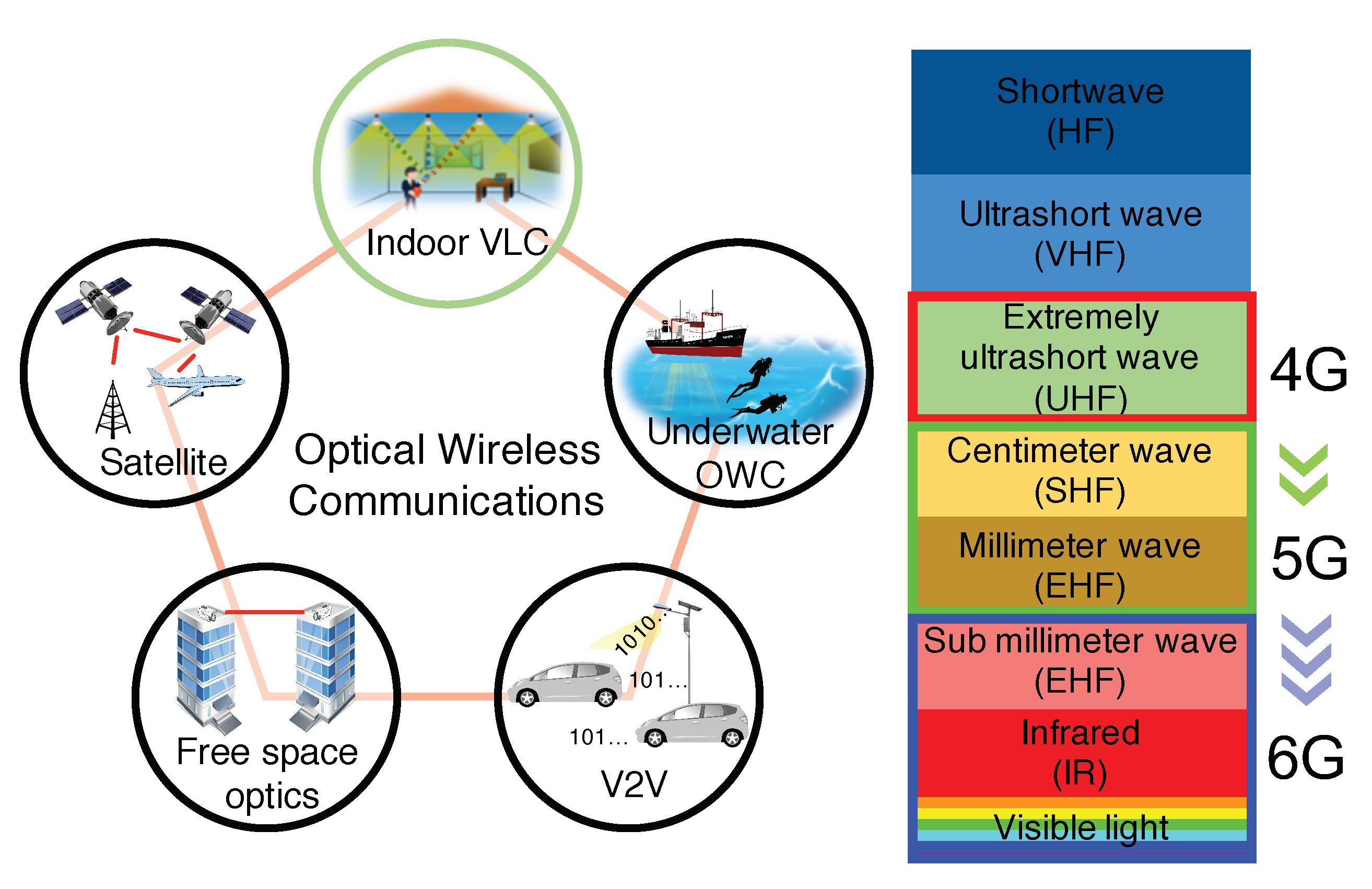
Wireless communication using radio frequency (RF) suffers from its limited bandwidth, which may result in a `spectrum crunch’ problem that restricts how fast we can access wireless data. In beyond-5G/6G, a promising solution to increase wireless communication capacity is to use a different part of the electromagnetic spectrum, such as the optical band. This emerging technology is known as optical wireless communication (OWC) and offers the significant advantage of utilizing large amounts of unregulated optical spectrum that is free to use.
OWC is typically classified into different categories based on the transceiver technologies and application scenarios, as depicted in Figure 1. Among the various forms of OWC, visible light communication (VLC) or LiFi has gained considerable research interest in the past two decades. VLC utilizes light-emitting diodes (LEDs) for both indoor illumination and data transmission. The inspiration behind VLC came from the rapid replacement of conventional incandescent and fluorescent light bulbs with LEDs for indoor lighting. In addition to their energy efficiency, LEDs can be directly modulated at very high frequencies, making them ideal for high-speed wireless transmission. Thanks to the development of various critical technologies, the transmission data rate of VLC has increased from a few Mbps to several tens of Gbps, making it a strong candidate for future wireless networks.
In this paper, we review the milestones in VLC’s development along with some important transmitter and receiver technologies used in VLC. In particular, one specific focus of this survey is on reviewing the research related to developing fast color converters that not only deliver high-quality illumination but also can enhance the bandwidth performance of the LED transmitter. Additionally, we provide a summary of the research conducted on developing fluorescent antennas at the receiver side. These antennas enable simultaneous optical filtering and light concentration while having a wide field of view (FOV). Moreover, we summarize the use of silicon photomultiplier (SiPM) sensors in VLC for detecting weak-intensity light and also highlight the unique non-linearity problem caused by the device’s dead time. In addition, we discuss the implementation of various types of angular diversity receivers in optical multiple-input–multiple-output (MIMO) transmission. Lastly, we outline the recent trends and future challenges in VLC research.
2. Milestones of VLC Research
Figure 2 shows some key milestones in the development of VLC technologies. Between the 1970s and 1990s, wireless infrared communication research received significant attention [1,2]. In 1997, J. M. Kahn and J. R. Barry published an important paper [3] analyzing the theoretical aspects of infrared communication systems. Many of its theories are also directly relevant to VLC research. Since 2000, energy-efficient LEDs have been rapidly replacing traditional incandescent lighting. The Nobel Prize in 2014 was awarded to three scientists, Isamu Akasaki, Hiroshi Amano, and Shuji Nakamura, for their invention of efficient blue LEDs in the 1980s and 1990s. The invention of blue LEDs has not only enabled bright and energy-saving white light sources but also paved the way for the idea of using LEDs for transmitting data. The current form of VLC, which uses white LEDs for both indoor illumination and data transmission, originated from Nakagawa Lab [4], Japan, in 2002 and has since generated substantial interest worldwide. In 2009, the University of Oxford successfully demonstrated a 100 Mbps VLC transmission link using on–off keying (OOK) modulation [5]. At the same time, VLC using optical orthogonal frequency-division multiplexing (OFDM) modulation also attracted attention. In 2006, J. Armstrong et al. invented a power-efficient optical OFDM modulation method that was later widely considered for both VLC and optical fiber systems [6]. In 2008, the home Gigabit Access Network (OMEGA) project [7,8,9] was established in Europe and aimed to achieve gigabit data rates for home users via both VLC and RF communications. In 2010, the OMEGA project successfully demonstrated a 513 Mbps VLC transmission link using OFDM modulation with bit loading [10]. In 2011, the term ’LiFi’ was first introduced by Prof. Harald Haas during a TEDGlobal talk and has attracted much attention from both the general public and the wireless industry [11]. During the same year, the IEEE 802.15.7 standard was formalized and defined the physical (PHY) and media access control (MAC) layer mechanisms for short-range optical wireless systems [12]. In recent years, the uses of multiplexing techniques, such as MIMO and wavelength-division multiplexing (WDM), to boost the transmission data rate have shown very promising performance. In 2013, the University of Oxford demonstrated a VLC system at 1 Gbps by the use of MIMO [13]. In 2015, Fudan University successfully demonstrated 8 Gbps VLC transmission using WDM with RGBY LEDs [14]. In 2016, the University of Oxford further increased this transmission data rate to 10 Gbps by using WDM and OFDM [15]. In 2019, using off-the-shelf LEDs, this data rate was increased to 15.73 Gbps by the University of Edinburgh [16]. In the same year, Fudan University successfully established an underwater VLC transmission link of 15 Gbps using RGBYC LEDs and WDM [17]. With various new technologies still under development, the VLC research community is aiming to improve the transmission data rate to Tbps using eye-safe lasers [18,19,20,21].
The transmission data rate is typically regarded as the most important criterion for evaluating the performance of a communication system. Over the past two decades, the data transmission rate of LED-based VLC has increased significantly from only a few Mbps to several tens of Gbps. Based on the type of LED used, a summary of different VLC systems demonstrated to date can be found in Table 1, Table 2, Table 3 and Table 4. Using representative work shown in these tables, Figure 3 illustrates how the achieved data transmission rate has been increased over time. Overall, when typical phosphor-coated white LEDs are used, the data transmission rate increases from 1 Mbps to several Gbps. The use of multi-chip RGB LEDs is seen to support the highest data rate thanks to the implementation of WDM to support parallel channels. Moreover, the use of LEDs enables Gbps data rates via a single transmission link because of their high modulation bandwidths [22]. Recently, the use of organic LEDs (OLEDs) in VLC has also gained a lot of interests since OLEDs have flexible structures and can be potentially manufactured at very low costs. However, due to the high capacitance of OLEDs, the transmission data rate is usually only several Mbps. In a recent study [23], by manufacturing special types of OLEDs for VLC, data transmission rates of more than 1 Gbps were also achieved. The significant improvement in VLC can be attributed to the development of numerous transceiver technologies. In the following sections, some key technologies are reviewed.
3. LED Transmitter
As depicted in Figure 3, the choice of the LED transmitter has a substantial influence on the performance of a VLC system. For indoor illumination purposes, the emitted light from the LED needs to be white. There are typically two categories of LEDs used for producing white light: multi-chip RGB LEDs and phosphor-based LEDs. As shown in Figure 4, in an RGB LED, three LED chips emit red, green, and blue light, respectively, to generate white light. Different from a RGB LED, a phosphor-based LED is comprised of a phosphor coating and a single blue LED. The phosphor coating converts a portion of the emitted blue light to yellow, and the combination of blue and yellow light is perceived as white light. Due to their low cost, phosphor-coated white LEDs are the most widely used LED type for illumination purposes.
3.1. LED Radiation Pattern
One important characteristic of an LED is its radiation pattern, which determines the relative light strength for different emission angles. In most of the VLC research, a Lambertian emitter [3] is used to model the radiation pattern of the LED. The Lambertian order, m, is related to the semi-angle of the LED, , by
Figure 5 shows the 3-D radiation pattern of the LED with different Lambertian orders. The radiation pattern of the LED is designed for illumination purposes but also significantly influences VLC performance. It can be seen that a higher value of the Lambertian order means the LED is more directional. If a bare photodiode with an area of A is placed at a position with a distance of d from the LED, the optical channel gain is given by
where is the emergence angle of the light and is the incident angle of the light.
In a VLC transmission scenario, the positions of the LED and the photodiode not only affect their distance but also influence both the emergence angle and incident angle of the light. Therefore, unlike most RF systems, the relative position between the transmitter and the receiver has a significant influence on the channel gain and thus affects the transmission performance. Using the Lambertian model, Figure 6 shows an example of how the illuminance is distributed in an office-like environment with a size of 10 m × 6 m. In this example, the vertical distance between the LED luminaires installed on the ceiling and the plane where the illumination level is simulated at 1.75 m, which is a typical distance between the ceiling and a table surface. The Lambertian order is considered to be one, and the positions of the luminaires are shown in Figure 6 using crosses. As expected, the positions directly below the LED luminaires have high illumination levels, e.g., 400 lx–500 lx. In contrast, the illumination levels are relatively low in the corners of the room, e.g., 100 lx. Importantly, it can be clearly seen that the light transmitted from each individual LED luminaire only covers a specific area. This implies that even within a limited space, users may only receive desired signals from a single transmitter without much interferences from other LED luminaires. As a result, the same frequency resources can be reused across different LED luminaires, allowing for the construction of a small indoor cellular system [56,57,58]. This is normally considered as an another significant advantage of VLC over its RF counterparts.
3.2. Fast Color Converter
Phosphor-based LEDs are currently the most commonly used light source for illumination, making them the popular type of transmitter in VLC research. However, the main limitation when using phosphor-based LEDs as VLC data transmitters is that, although the blue LED can be modulated up to high frequencies, due to the slow photoluminescence (PL) lifetime of the phosphor coating, the generated white light can only be modulated at frequencies up to few megahertz [59]. This is normally known as the `phosphor bottleneck’ problem in VLC and results in a trending research topic on developing new color converters with short PL lifetime to replace the phosphor coating for generating high-quality white light.
A good color converter for VLC applications should possess several important features. Firstly, it should have strong absorption of blue light emitted from Gallium Nitride (GaN) LEDs, typically at 450 nm. Secondly, it should have a high photoluminescence quantum yield (PLQY) to ensure that most absorbed photons lead to the emission of new photons with longer wavelengths rather than non-radiative decay. Thirdly, the generated white light should have good illumination quality, as usually measured by the color rendering index (CRI). Finally, the color converter should have a PL lifetime shorter than the carrier recombination lifetime of the LED so that the bandwidth of the LED is not affected. For both the GaN LED and the color converter, the exponential decay of the processes that lead to emission of photons results in a single-pole response in the frequency domain, given by [60]
where is either the PL lifetime of the color converter or the carrier recombination lifetime of the GaN LED. Therefore, the frequency response of the signal power is
In this case, the 3 dB bandwidth is given by
which is inversely proportional to the PL lifetime. Consequently, a short PL lifetime of the color converter is very desirable for communication purposes.
In the past, several different fast color converters have been developed for VLC applications. In reference [48], the color converter “super yellow”, which is a type of conjugated polymer, was combined with a blue LED to produce high-quality white light. A breakthrough transmission data rate of 1.68 Gbps was achieved at a standard illumination level of 240 lx. Following this, the organic materials group at the University of St Andrews and the optical wireless group at the University of Oxford collaborated to investigate several organic materials for developing fast color converters [61,62,63,64]. For example, some studied materials, such as BBEHP-PPV ( ns), exhibited PL lifetimes of less than one nanosecond [61]. Additionally, by using advanced cascade energy transfer principles, a high-performance color converter that enables the shifting of the emission spectrum from green to red with both a high PLQY and a short PL lifetime was created [64]. In more recent studies, in addition to organic materials, there is also a trend to explore some inorganic perovskite nanocrystals, or quantum dots, for creating fast color converters, and many transmission systems have been demonstrated with very promising performance [65,66,67,68,69,70,71].
4. VLC Receiver
In addition to the LED transmitter, the design of the receiver also plays an important role in VLC. As shown in Figure 7, a typical VLC receiver consists of an optical filter, an optical concentrator, and a photodiode. The optical filter selects the wavelength of the light to be detected. The optical concentrator is used to increase the received optical power. The photodiode converts the optical intensity signal into an electrical signal. In many receiver designs, the photodiode is also connected with a transimpedance amplifier (TIA) so that the current signal is converted into a voltage signal.
4.1. Optical Filter
An optical filter can improve the overall performance of the VLC system in several ways. For instance, when using a phosphor-based LED as the data transmitter, a blue filter is usually placed before the photodiode to filter out the yellow light and thus increase the transmission bandwidth. However, in some studies [72,73], it was found that blue filtering does not always improve the transmission performance. The usefulness of blue filtering depends on a range of factors such as the transmission data rate, the frequency range utilized, the effectiveness of the equalizer, the noise level, and even the LED spectrum [72]. This is because if the transmission sampling rate is not too high and very high frequencies are not used, the yellow light still carries information. In this case, using proper equalization techniques, the frequency response caused by both the blue LED and the phosphor can be well equalized and the noise component after equalization is acceptable; the use of blue filtering may not be necessary and may even reduce the performance. In contrast, when the transmission sampling rate becomes high or very high frequencies are utilized, the yellow light carries no information at these frequencies but only introduces shot noise. In this situation, a blue filter can be placed to filter out the yellow light and thus reduce the shot noise. If no blue filtering is used, the equalization can result in significant noise enhancement, which affects the overall transmission performance. Another important function of optical filtering is to effectively separate light of various colors, thus preventing crosstalk between different channels when RGB LEDs or lasers are employed as data transmitters, enabling WDM to achieve high data transmission rates [74].
4.2. Optical Concentrator
In VLC, the received optical power of the light is proportional to the area of the photodiode. However, the capacitance of the photodiode increases when the area of the photodiode increases, and a high capacitance limits the bandwidth of the receiver. To support a high modulation bandwidth, the size of the photodiode needs to be small. Therefore, an optical concentrator is usually placed in front of the photodiode to increase the received optical power for a given photodiode area. The most common concentrators include lenses and compound parabolic concentrators (CPCs). However, these concentrators cannot achieve both high concentration gain and a wide FOV; this is known as the étendue limit [3]. Using typical optical concentrators, the maximum concentration gain, , and the FOV, , are related by
where n is the refractive index of the concentrator. When a concentrator and an optical filter are used, the optical channel gain shown in (2) can be adapted to give
where is the transmission coefficient of the optical filter, which may also vary with the incident angle of the light, especially when narrow-band interference filters are used.
In addition to limiting the receiver’s FOV, placing both an optical filter and an optical concentrator in front of the photodiode can also result in a bulky receiver structure, such as the example shown in Figure 7, which is not suitable for small devices such as IoT devices.
4.3. Fluorescent Antenna
To build compact VLC receivers with wide FOVs, a new approach of using optical antennas made of fluorescent materials has been recently studied and shows very promising performance. In addition to their wide FOVs, these antennas are capable of simultaneous optical filtering and light concentration. Figure 8a shows the main physical processes of the light within the fluorescent antenna. When the incident light arrives at the antenna surface, depending on the incident angle of the light, part of the light is reflected back into the air and the rest of the light transmits into the antenna. Within the antenna, the light can pass through the antenna if the wavelength of the light is not within the absorption range of the fluorophore. Alternatively, a photon can be absorbed by the fluorophore. This absorption can be relaxed non-radiatively or it can result in the emission of a photon with longer wavelengths. Since the emitted photons can go in any direction, as shown in Figure 8a, these photons can escape the antenna or be re-absorbed by the fluorophore. At the same time, many photons can be waveguided to the antenna end where a photodiode is placed. Overall, due to these physical processes, a single fluorescent antenna has many functions. First, because the fluorescent materials only absorb light of certain wavelengths, therefore the antennas have the functions of optical filtering. Second, the antennas are designed to have both a cladding layer and a core layer so that many emitted photons from the fluorophores can be trapped within the antenna and guided to the photodiodes. Thus, they are capable of light concentration. Third, since its light concentration principle is based on fluorescence rather than reflection and refraction, it can exceed the étendue limit and achieve both high light concentration gain and a wide FOV. Additionally, since fluorophores with very short PL lifetimes can be selected. The antennas can provide very high transmission bandwidths.
The idea of fluorescent antennas was originally from the study of luminescent solar concentrators (LSCs) [75], and it was then first studied for use in OWCs in [76] for building a wide-FOV receiver. After that, several different antenna structures and fluorescent materials have been explored and tested in different OWC systems. In reference [77], an optical antenna structure made of a fluorescent layer sandwiched between two glass microscope slides was introduced. The fluorescent layer contained an organic fluorescent dye, Coumarin-6 (Cm6), which has strong absorption of 450 nm blue light. The performance of this antenna was studied in a blue LED-based VLC system. In reference [78], this structure was extended to include a second organic fluorescent layer made of 4-(Dicyanomethylene)-2-methyl-6-(4-dimethylaminostyryl)-4H-pyran (DCM) dye, which can absorb green light greater than 500 nm. In this case, this structure can support WDM techniques to boost the transmission data rate when a multi-chip RGB LED is used as the data transmitter. However, the significant drawback of this structure is that it has four wide rectangular edges, and most of the photons that are guided to the antenna edges cannot be detected. To overcome its structure problem, capillary-based antennas were introduced in [79]. A photo of these antennas, which are made of Coumarin-504 (Cm504), Cm6, and DCM, is shown in Figure 8b. In addition to organic materials, some inorganic materials have also been studied. For example, in [80], perovskite nanocrystals were considered to make an optical antenna with a polymer-fiber structure. Its performance was demonstrated in an underwater optical wireless transmission link. Another popular approach to designing optical antennas is to use commercially available fluorescent fibers [81,82,83,84,85,86]. Figure 8c shows one example of a florescent antenna made of two bent fibers that have strong absorption of 450 nm blue light and emission of green light. The benefits of using fluorescent fibers as optical antennas include their flexible structure and the advanced fiber cladding technique that increases photon trap efficiency. In recent studies [87,88,89], the concept of utilizing a commercially available light-diffusing fiber (LDF) to construct a wide-FOV OWC system was also introduced. In this approach, the end of the LDF fiber is connected to a light source that transmits the signal. Due to the scattering of light in various directions within the fiber and its uniform emission from the fiber surface, this technique enables the use of movable receivers.

4.4. Photodetector
In VLC systems, the received light intensity is converted into an electrical signal using a photodetector at the receiver. Two commonly used types of photodiodes are positive–intrinsic–negative (PIN) photodiodes and avalanche photodiodes (APDs). Although the cost of PIN photodiodes is typically much lower than that of APDs, APDs are significantly more sensitive due to the signal amplification resulting from avalanche multiplication. However, the drawback of using an APD is that it produces excess noise [90]. One way to further improve the sensitivity of the receiver is to bias an APD above its breakdown voltage, known as the Geiger mode, to create a single-photon avalanche detector (SPAD) [91,92]. Although SPADs are very sensitive and can detect individual photons, their operational mechanism means that the SPAD needs a period to recover after detecting a single photon. This is usually known as the dead time or the recovery period [91]. Figure 9 shows three simulation trials of the photon detection process with the impact of the SPAD’s dead time when different irradiance levels are considered. As observed in Figure 9a, no photons are missed when the irradiance level is low. However, as illustrated in Figure 9b,c, an increase in irradiance results in a rise in both the number of photons arriving at the SPAD and the number of missed photons.
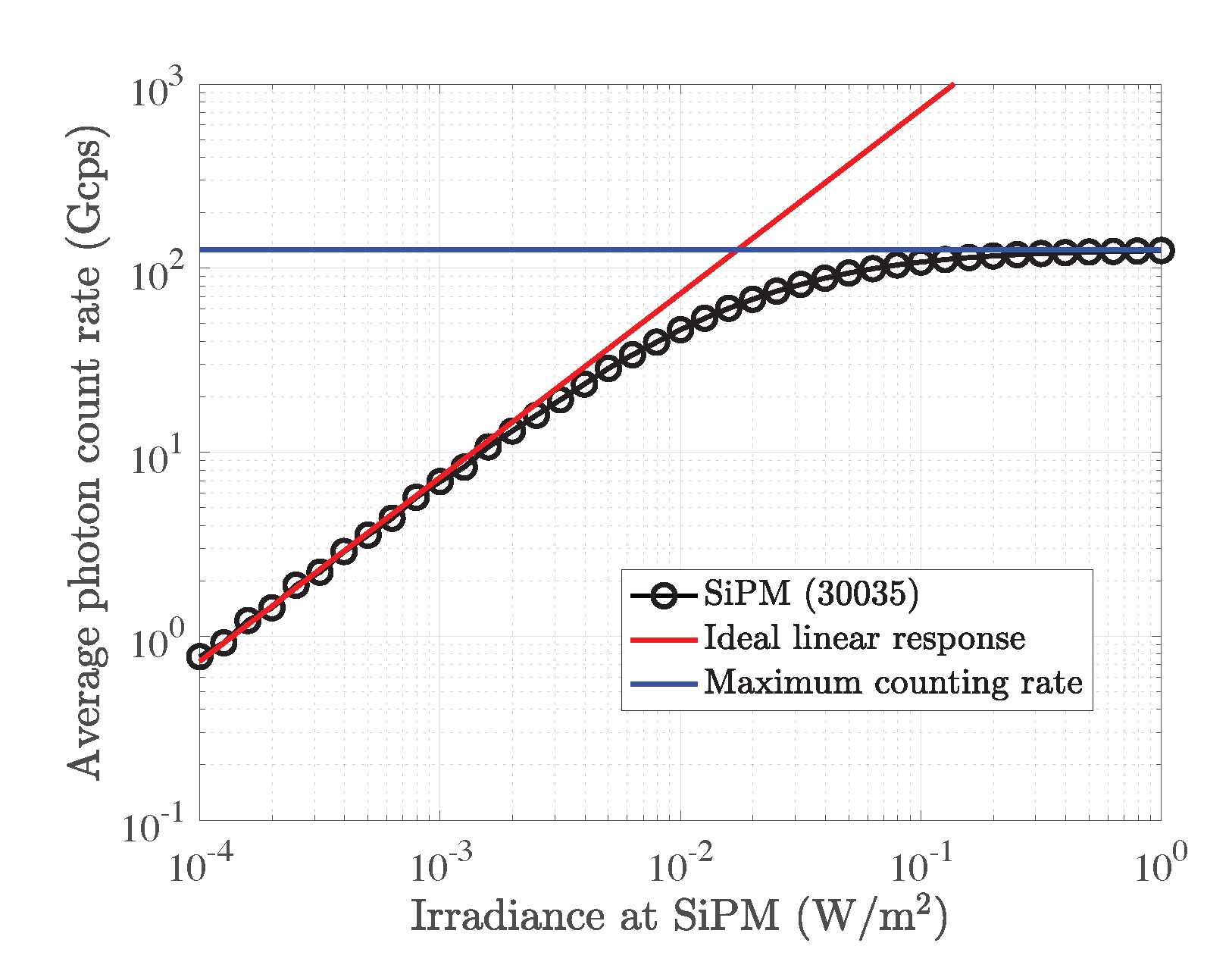
In recent studies, the use of a SPAD array sensor, known as SiPM or multi-pixel photon counter (MPPC), in VLC shows very impressive results, particularly when the received light is weak [93,94,95,96]. Thanks to advanced silicon fabrication techniques, a single SiPM sensor, only a few millimeters in size, can contain thousands of SPADs. Compared to a single SPAD, the use of a SPAD array ensures that even if some SPADs become inactive after detecting photons, other active SPADs can continue to detect them. This also provides a wide dynamic range of the quantized photon-counting signal to support advanced modulation techniques such as OFDM [97,98,99,100]. However, the dead time of individual SPADs still significantly impacts transmission and causes a non-linear response when a SiPM is used to detect light intensity signals. Figure 10 shows the nonlinear relationship between the average photon counting rate and the irradiance at the SiPM with a SiPM 30035 chip manufactured by Onsemi considered. Since SiPMs are non-paralyzable detectors, it also can be seen that the maximum photon counting rate is given by
where represents the number of SPADs within a SiPM and denotes the dead time. When the transmission sampling rate is low, the nonlinearity caused by the SPAD dead time can cause attenuation in individual signal samples. However, when the transmission sampling rate is high, the dead time can span several symbol periods, as shown in Figure 9b,c, introducing a unique form of ISI. To address the nonlinearity problem caused by SPAD dead time, various pre- and post-equalization techniques have been explored in recent studies [101,102], including using different forms of artificial neural networks [103,104]. As SiPM chip fabrication techniques continue to advance, SiPM sensors are becoming increasingly suitable for low-light-intensity environments, such as underwater OWC [105,106,107], eye-safe laser-based OWC [108,109], and free space optics (FSO)-based applications for unmanned aerial vehicles (UAVs) [110,111,112].
4.5. Optical MIMO Receiver
In most indoor environments, the illumination is typically provided by several LED luminaires that are spaced at intervals on the ceiling. By using these LED luminaires as data transmitters and multiple photodiodes at the receiver, it is possible to achieve VLC MIMO transmission [113,114,115]. Several types of VLC MIMO systems are commonly employed, including spatial multiplexing (SMP), optical spatial modulation (OSM), and indoor VLC cellular systems.
An important indoor VLC MIMO configuration utilizes SMP [116,117,118] in which independent data are transmitted from each of the LED luminaires. Figure 11a depicts the transmitters, L1, L2, L3, and L4, transmitting independent data streams to the user devices, U1 and U2. Multiple photodiodes are used in each user device to receive the transmitted signals, which are then sent to a de-multiplexing module for separation. The independent transmission of data from LEDs means that SMP configuration can support high data rates.
Another important VLC MIMO configuration is OSM [119,120,121,122], which is illustrated in Figure 11b. In the simplest form of OSM, the transmission is divided into short time slots and only one LED luminaire is active during each time slot. Information is conveyed through both the data symbols modulated on the light intensity and the index of the active LED luminaire. Multi-stream interference (MSI) is avoided in OSM since only one LED is active. However, this is achieved at the expense of a significant reduction in data rate. To enhance the transmission data rate of OSM, generalized OSM can be considered, in which during each time slot, multiple LED luminaires are active to transmit some information [123] or independent data streams [124]. Consequently, more bits of information are modulated into the index of the active LED luminaires and the performance is enhanced via diversity combining or multiplexing.
A more feasible configuration in an indoor environment is a cellular system wherein the data intended for a particular user are transmitted by the closest luminaire [125]. As shown in Figure 11c, the user’s possible location is divided into different cells, with each cell having a corresponding LED luminaire. The luminaire transmits signals to the users within its cell. For instance, user U1 receives the desired signal from the luminaire located above, while U2 receives the desired signal from a different luminaire. Multiplexing techniques such as time-division multiple access (TDMA), code-division multiple access (CDMA), orthogonal frequency-division multiple access (OFDMA), and non-orthogonal multiple access (NOMA) [126] can be utilized to enable multiple users to be supported by each cell.
In all of the optical MIMO configurations, the receiver must be able to successfully separate signals transmitted from different sources. However, the characteristics of the transmitters, channel, and receivers used in VLC systems mean that the separation of the signals is difficult. In VLC, the received optical power varies slowly as a function of PD position. As shown in Figure 12, when using multiple PDs with the same orientation, the channels between the PDs and a particular LED luminaire become highly similar in the case of a small receiver such as a smartphone. This creates an ill-conditioned channel matrix where each column of the matrix has nearly identical values. This means that it becomes difficult to separate the signals without significant noise enhancement.
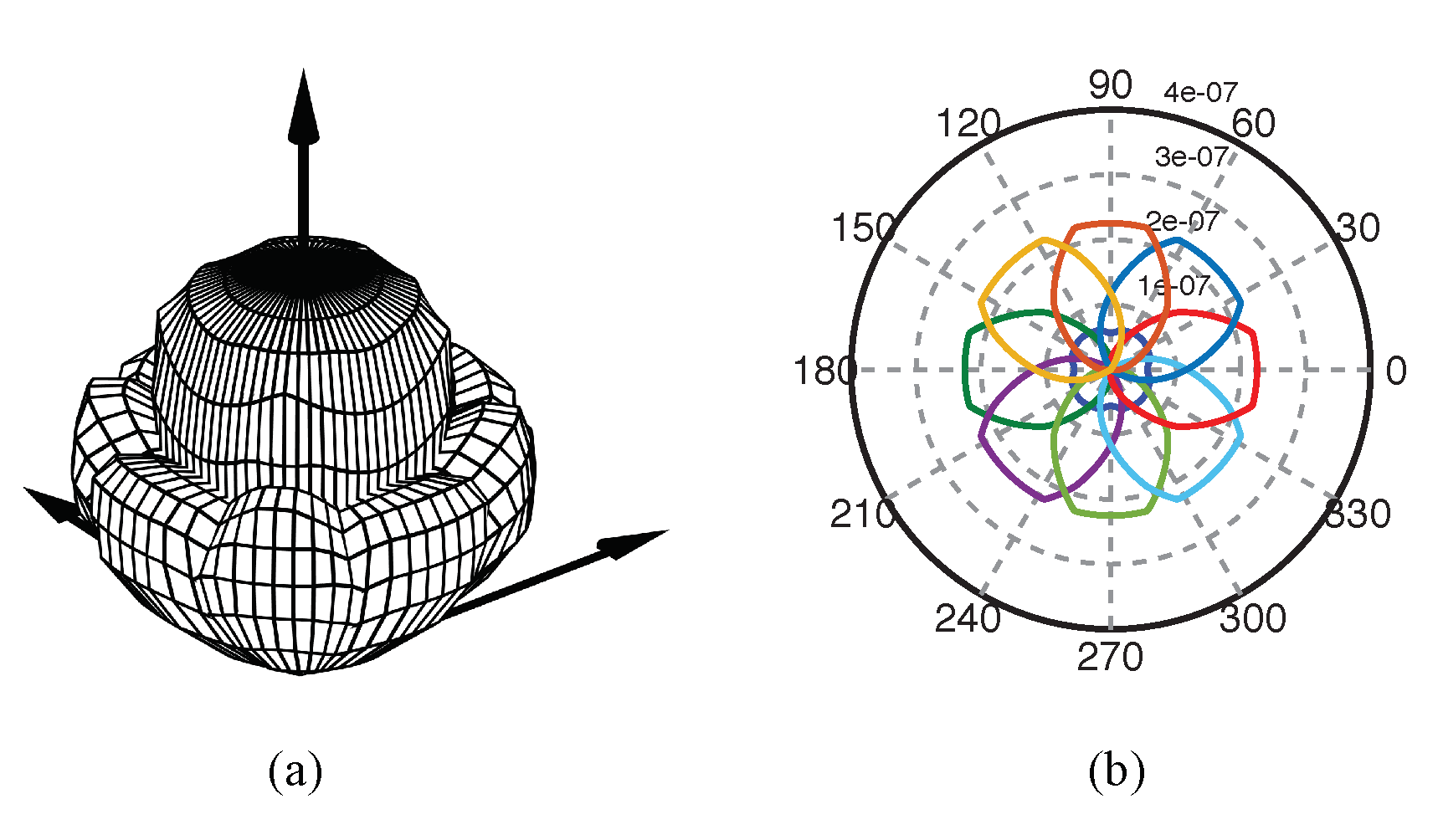
To improve the MIMO channel condition, optical receivers play an important role. Currently, the optical MIMO receiver can be classified into two categories, including imaging receivers and non-image receivers. In the case of an imaging receiver, an imaging lens is used to completely separate the signals in the optical domain [44,116,127]. One example is shown in Figure 13a. To increase the FOV of the imaging receiver, a hemispherical-lens-based receiver is introduced in [117], and its structure is shown in Figure 13b. Although the hemispherical lens can only partially separate the signal in some cases, it can still result in a well-conditioned channel matrix that enables the signals to be successfully separated in the electrical domain using de-multiplexing techniques. In the case of the non-imaging receiver, angular diversity receivers are usually used. One simple way to create an angular diversity receiver is to place the photodiodes in a way that they can face in different directions. One example uses a pyramid structure, as shown in Figure 13c [128]. Other similar structures are studied in [125,129,130,131]. Reference [125] shows that the facing angles of the photodiodes can be optimized based on considered indoor scenarios. However, these three-dimensional receivers can hardly be incorporated into a device without any protrusions. To build optical MIMO receivers with a planar surface, a prism-based receiver is introduced in [132]. As shown in Figure 13d, by using prisms with different orientations, the photodiode placed below the prism only receives light from certain directions and, thus, angular diversity is achieved. Another approach is using an angular diversity aperture receiver (ADA), as shown in Figure 13e. An ADA receiver contains multiple receiving elements (REs), and each RE consists of an aperture and a photodiode [133,134,135]. The key feature of the ADA receiver is that the positions of the photodiodes are different in different REs. By adjusting the relative position between the aperture and the photodiode, a directional MIMO receiver is created and the FOV of each RE is also adjustable. This structure can be further used to create MIMO receivers with different FOVs for improving the channel condition [136]. A similar structure, named the `quadrature angular diversity aperture receiver (QADA)’, is also studied in [137,138] for angle-of-arrival (AoA)-based VLP systems. Figure 13e illustrates an ADA receiver with nine REs. To show the directionality of this receiver, the 3D receiving pattern and the associated polar plot of the receiver are shown in Figure 14. It can be seen that although a single RE has a very limited FOV, using multiple REs can achieve an overall large FOV.
5. Recent Trends and Future Challenges
Although LEDs are extensively used in various indoor environments, making them convenient choices for optical wireless transmitters, their modulation bandwidths remain relatively limited. This limitation has the potential to restrict the achievable transmission data rates in the near future. The VLC research community is currently exploring the use of eye-safe lasers, often referred to as LiFi 2.0, to achieve transmission rates in the Tbps range [20]. Unlike LEDs, lasers offer significantly higher modulation bandwidths. However, the need for safety compliance, such as the constraints outlined in the IEC 60825-1 standard, requires limiting the laser’s output power. Recent studies have demonstrated that vertical-cavity surface-emitting lasers (VCSELs) can achieve data rates in the Gbps range while ensuring eye-safe conditions [109]. Additionally, the utilization of broad beams eliminates the requirement for using high-cost beam-steering techniques, enabling the coverage of large areas and offering significant benefits for supporting mobile users. VCSELs also offer numerous advantages as data transmitters, including extremely high modulation bandwidths (>10 GHz) and the ability to densely pack them in large arrays within a single access point (AP), enabling support for transmission scenarios such as MIMO [21] and indoor atto-cells [109]. Currently, the development of LiFi 2.0 is still in its early stages, and the goal of establishing stable Tbps transmission links is being actively pursued through collaborative efforts by several major OWC research groups.
Despite the numerous advantages of VLC, it still faces several challenges compared to its RF counterparts. Firstly, in many VLC systems that employ broad beams of light, the transmission distance is often limited. This limitation is particularly prominent in IM/DD-based VLC systems, where the transmitted signal is directly modulated onto the optical power of the light. In such cases, the amplitude of the received electrical signal is inversely proportional to the square of the distance. Consequently, as the distance increases, the power of the electrical signal decreases even more rapidly. Secondly, in most VLC experiments, achieving high transmission data rates is only feasible when a LOS link exists between the transmitter and receiver, as the diffuse component of the light is typically much weaker. Although photon-counting sensors are capable of detecting light with extremely weak intensity, designing optical filtering systems that allow a wide FOV while effectively rejecting ambient light to prevent the sensor from being saturated can be significantly challenging. Thirdly, most high-speed VLC transmissions can only be demonstrated in laboratory-based experiments that rely on expensive optics or specially designed electronics. If VLC is to be implemented in real-life applications, it becomes essential to focus on reducing costs to meet practical requirements.
6. Conclusions
Over the last two decades, there has been a significant growing interest in the development of VLC technologies for a variety of wireless applications. This growth can be attributed to a range of advanced transmission techniques. First, thanks to the invention of different types of LEDs, high-transmission bandwidths were achieved, which allows Gbps data rates. Additionally, to solve the “phosphor bottleneck” problem and provide high-quality white light, researchers have investigated various materials with short PL lifetimes. The developed technologies allow the bandwidth of white-light-emitting transmitters to increase from just several megahertz to several hundred megahertz for supporting Gbps links. Advanced photodetectors and optics at the receiver have also significantly contributed to the development of VLC systems. Recent studies on fluorescent antennas have enabled the creation of a compact wide-FOV receiver with dual functions of optical filtering and light concentration. Moreover, the use of super-sensitive optical sensors, such as the SiPM chip, has allowed for the use of VLC in special environments with extremely low light intensity, such as underwater OWC. We hope that the continued development of these emerging techniques will make VLC a strong candidate for the next-generation wireless communication network.
Author Contributions
Conceptualization, C.H. and C.C.; writing—original draft preparation, C.H.; writing—review and editing, C.H. and C.C.; funding acquisition, C.H. All authors have read and agreed to the published version of the manuscript.
Funding
The work of Cuiwei He was supported by the Japan Society for the Promotion of Science (JSPS) KAKENHI under grant JP 23K13332.
Institutional Review Board Statement
Not applicable.
Informed Consent Statement
Not applicable.
Data Availability Statement
The data of this study are available from the corresponding author upon request.
Conflicts of Interest
The authors declare no conflict of interest.
References
- Barry, J.R. Wireless Infrared Communications; Springer Science & Business Media: New York, NY, USA, 1994; Volume 280. [Google Scholar]
- Gfeller, F.R.; Bapst, U. Wireless in-house data communication via diffuse infrared radiation. Proc. IEEE 1979, 67, 1474–1486. [Google Scholar] [CrossRef]
- Kahn, J.M.; Barry, J.R. Wireless infrared communications. Proc. IEEE 1997, 85, 265–298. [Google Scholar] [CrossRef] [Green Version]
- Komine, T.; Nakagawa, M. Fundamental analysis for visible-light communication system using LED lights. IEEE Trans. Consum. Electron. 2004, 50, 100–107. [Google Scholar] [CrossRef]
- Le Minh, H.; O’Brien, D.; Faulkner, G.; Zeng, L.; Lee, K.; Jung, D.; Oh, Y.; Won, E.T. 100-Mb/s NRZ visible light communications using a postequalized white LED. IEEE Photonics Technol. Lett. 2009, 21, 1063–1065. [Google Scholar] [CrossRef]
- Armstrong, J.; Lowery, A.J. Power efficient optical OFDM. Electron. Lett. 2006, 42, 1. [Google Scholar] [CrossRef] [Green Version]
- O’Brien, D. High speed optical wireless demonstrators in the omega project: Summary and conclusions. In Proceedings of the 18th European Conference on Network and Optical Communications & 8th Conference on Optical Cabling and Infrastructure (NOC-OC&I), Graz, Austria, 10–12 July 2013; pp. 159–162. [Google Scholar]
- Javaudin, J.P.; Bellec, M.; Varoutas, D.; Suraci, V. OMEGA ICT project: Towards convergent Gigabit home networks. In Proceedings of the IEEE 19th International Symposium on Personal, Indoor and Mobile Radio Communications, Cannes, France, 15–18 September 2008; pp. 1–5. [Google Scholar]
- Javaudin, J.P.; Bellec, M. Omega project: On convergent digital home networks. In Proceedings of the 3d International Workshop on Cross Layer Design, Rennes, France, 30 November–1 December 2011; pp. 1–5. [Google Scholar]
- Vučić, J.; Kottke, C.; Nerreter, S.; Langer, K.D.; Walewski, J.W. 513 Mbit/s visible light communications link based on DMT-modulation of a white LED. J. Light. Technol. 2010, 28, 3512–3518. [Google Scholar] [CrossRef]
- Haas, H.; Yin, L.; Wang, Y.; Chen, C. What is lifi? J. Light. Technol. 2015, 34, 1533–1544. [Google Scholar] [CrossRef]
- IEEE Association. IEEE Standard for Local and Metropolitan Area Networks-Part 15.7: Short-Range Wireless Optical Communication Using Visible Light; IEEE: Piscataway, NJ, USA, 2011; pp. 1–309. [Google Scholar]
- Azhar, A.H.; Tran, T.A.; O’Brien, D. A gigabit/s indoor wireless transmission using MIMO-OFDM visible-light communications. IEEE Photonics Technol. Lett. 2012, 25, 171–174. [Google Scholar] [CrossRef]
- Wang, Y.; Tao, L.; Huang, X.; Shi, J.; Chi, N. 8-Gb/s RGBY LED-based WDM VLC system employing high-order CAP modulation and hybrid post equalizer. IEEE Photonics J. 2015, 7, 1–7. [Google Scholar]
- Chun, H.; Rajbhandari, S.; Faulkner, G.; Tsonev, D.; Xie, E.; McKendry, J.J.D.; Gu, E.; Dawson, M.D.; O’Brien, D.C.; Haas, H. LED based wavelength division multiplexed 10 Gb/s visible light communications. J. Light. Technol. 2016, 34, 3047–3052. [Google Scholar] [CrossRef] [Green Version]
- Bian, R.; Tavakkolnia, I.; Haas, H. 15.73 Gb/s visible light communication with off-the-shelf LEDs. J. Light. Technol. 2019, 37, 2418–2424. [Google Scholar] [CrossRef] [Green Version]
- Zhou, Y.; Zhu, X.; Hu, F.; Shi, J.; Wang, F.; Zou, P.; Liu, J.; Jiang, F.; Chi, N. Common-anode LED on a Si substrate for beyond 15 Gbit/s underwater visible light communication. Photonics Res. 2019, 7, 1019–1029. [Google Scholar] [CrossRef]
- Kazemi, H.; Sarbazi, E.; Soltani, M.D.; Safari, M.; Haas, H. A Tb/s indoor optical wireless backhaul system using VCSEL arrays. In Proceedings of the IEEE 31st Annual International Symposium on Personal, Indoor and Mobile Radio Communications, London, UK, 31 August–3 September 2020; pp. 1–6. [Google Scholar]
- Hong, Y.; Feng, F.; Bottrill, K.R.; Taengnoi, N.; Singh, R.; Faulkner, G.; O’Brien, D.C.; Petropoulos, P. Demonstration of >1Tbit/s WDM OWC with wavelength-transparent beam tracking-and-steering capability. Opt. Express 2021, 29, 33694–33702. [Google Scholar] [CrossRef]
- Soltani, M.D.; Kazemi, H.; Sarbazi, E.; Qidan, A.A.; Yosuf, B.; Mohamed, S.; Singh, R.; Berde, B.; Chiaroni, D.; Béchadergue, B.; et al. Terabit Indoor Laser-Based Wireless Communications: LiFi 2.0 for 6G. arXiv 2022, arXiv:2206.10532. [Google Scholar]
- Kazemi, H.; Sarbazi, E.; Soltani, M.D.; El-Gorashi, T.E.; Elmirghani, J.M.; Penty, R.V.; White, I.H.; Safari, M.; Haas, H. A Tb/s indoor mimo optical wireless backhaul system using VCSEL arrays. IEEE Trans. Commun. 2022, 70, 3995–4012. [Google Scholar] [CrossRef]
- Wei, Z.; Wang, L.; Li, Z.; Chen, C.J.; Wu, M.C.; Wang, L.; Fu, H. Micro-LEDs Illuminate Visible Light Communication. IEEE Commun. Mag. 2023, 61, 108–114. [Google Scholar] [CrossRef]
- Yoshida, K.; Manousiadis, P.P.; Bian, R.; Chen, Z.; Murawski, C.; Gather, M.C.; Haas, H.; Turnbull, G.A.; Samuel, I.D. 245 MHz bandwidth organic light-emitting diodes used in a gigabit optical wireless data link. Nat. Commun. 2020, 11, 1171. [Google Scholar] [CrossRef] [Green Version]
- Zhou, Y.; Wei, Y.; Hu, F.; Hu, J.; Zhao, Y.; Zhang, J.; Jiang, F.; Chi, N. Comparison of nonlinear equalizers for high-speed visible light communication utilizing silicon substrate phosphorescent white LED. Opt. Express 2020, 28, 2302–2316. [Google Scholar] [CrossRef]
- Ji, Y.w.; Wu, G.f.; Wang, C.; Zhang, E.f. Experimental study of SPAD-based long distance outdoor VLC systems. Opt. Commun. 2018, 424, 7–12. [Google Scholar] [CrossRef]
- Huang, X.; Chen, S.; Wang, Z.; Shi, J.; Wang, Y.; Xiao, J.; Chi, N. 2.0-Gb/s visible light link based on adaptive bit allocation OFDM of a single phosphorescent white LED. IEEE Photonics J. 2015, 7, 1–8. [Google Scholar] [CrossRef]
- Huang, X.; Wang, Z.; Shi, J.; Wang, Y.; Chi, N. 1.6 Gbit/s phosphorescent white LED based VLC transmission using a cascaded pre-equalization circuit and a differential outputs PIN receiver. Opt. Express 2015, 23, 22034–22042. [Google Scholar] [CrossRef] [PubMed]
- Wu, F.M.; Lin, C.T.; Wei, C.C.; Chen, C.W.; Huang, H.T.; Ho, C.H. 1.1-Gb/s white-LED-based visible light communication employing carrier-less amplitude and phase modulation. IEEE Photonics Technol. Lett. 2012, 24, 1730–1732. [Google Scholar] [CrossRef] [Green Version]
- Khalid, A.; Cossu, G.; Corsini, R.; Choudhury, P.; Ciaramella, E. 1-Gb/s transmission over a phosphorescent white LED by using rate-adaptive discrete multitone modulation. IEEE Photonics J. 2012, 4, 1465–1473. [Google Scholar] [CrossRef] [Green Version]
- Grubor, J.; Lee, S.C.J.; Langer, K.D.; Koonen, T.; Walewski, J.W. Wireless high-speed data transmission with phosphorescent white-light LEDs. In Proceedings of the 33rd European Conference and Exhibition of Optical Communication-Post-Deadline Papers; Research Gate: Berlin, Germany, 2008; pp. 1–2. [Google Scholar]
- Afgani, M.Z.; Haas, H.; Elgala, H.; Knipp, D. Visible light communication using OFDM. In Proceedings of the 2nd International Conference on Testbeds and Research Infrastructures for the Development of Networks and Communities, Barcelona, Spain, 1–3 March 2006; pp. 1–6. [Google Scholar]
- Komine, T.; Nakagawa, M. Integrated system of white LED visible-light communication and power-line communication. IEEE Trans. Consum. Electron. 2003, 49, 71–79. [Google Scholar] [CrossRef] [Green Version]
- Hu, F.; Chen, S.; Li, G.; Zou, P.; Zhang, J.; Hu, J.; Zhang, J.; He, Z.; Yu, S.; Jiang, F.; et al. Si-substrate LEDs with multiple superlattice interlayers for beyond 24 Gbps visible light communication. Photonics Res. 2021, 9, 1581–1591. [Google Scholar] [CrossRef]
- Lu, I.C.; Lai, C.H.; Yeh, C.H.; Chen, J. 6.36 Gbit/s RGB LED-based WDM MIMO visible light communication system employing OFDM modulation. In Proceedings of the Optical Fiber Communication Conference, Los Angeles, CA, USA, 19–23 March 2017; p. W2A.39. [Google Scholar]
- Kosman, J.; Almer, O.; Jalajakumari, A.V.; Videv, S.; Haas, H.; Henderson, R.K. 60 Mb/s, 2 m visible light communications in 1 klx ambient using an unlensed CMOS SPAD receiver. In Proceedings of the IEEE Photonics Society Summer Topical Meeting Series (SUM), Newport Beach, CA, USA, 11–13 July 2016; pp. 171–172. [Google Scholar]
- Wang, Y.; Huang, X.; Tao, L.; Shi, J.; Chi, N. 4.5-Gb/s RGB-LED based WDM visible light communication system employing CAP modulation and RLS based adaptive equalization. Opt. Express 2015, 23, 13626–13633. [Google Scholar] [CrossRef] [PubMed]
- Wang, Y.; Huang, X.; Zhang, J.; Wang, Y.; Chi, N. Enhanced performance of visible light communication employing 512-QAM N-SC-FDE and DD-LMS. Opt. Express 2014, 22, 15328–15334. [Google Scholar] [CrossRef]
- Cossu, G.; Khalid, A.; Choudhury, P.; Corsini, R.; Ciaramella, E. 3.4 Gbit/s visible optical wireless transmission based on RGB LED. Opt. Express 2012, 20, B501–B506. [Google Scholar] [CrossRef]
- Kottke, C.; Hilt, J.; Habel, K.; Vučić, J.; Langer, K.D. 1.25 Gbit/s visible light WDM link based on DMT modulation of a single RGB LED luminary. In Proceedings of the European Conference and Exhibition on Optical Communication, Amsterdam, The Netherlands, 16–20 September 2012; pp. 1–3. [Google Scholar]
- Xu, F.; Qiu, P.; Tao, T.; Tian, P.; Liu, X.; Zhi, T.; Xie, Z.; Liu, B.; Zhang, R. High Bandwidth Semi-Polar InGaN/GaN Micro-LEDs with Low Current Injection for Visible Light Communication. IEEE Photonics J. 2023, 15, 7300704. [Google Scholar] [CrossRef]
- Qiu, P.; Zhu, S.; Jin, Z.; Zhou, X.; Cui, X.; Tian, P. Beyond 25 Gbps optical wireless communication using wavelength division multiplexed LEDs and micro-LEDs. Opt. Lett. 2022, 47, 317–320. [Google Scholar] [CrossRef]
- Chang, Y.H.; Huang, Y.M.; Gunawan, W.H.; Chang, G.H.; Liou, F.J.; Chow, C.W.; Kuo, H.C.; Liu, Y.; Yeh, C.H. 4.343-Gbit/s green semipolar (20-21) μ-LED for high speed visible light communication. IEEE Photonics J. 2021, 13, 1–4. [Google Scholar] [CrossRef]
- Islim, M.S.; Ferreira, R.X.; He, X.; Xie, E.; Videv, S.; Viola, S.; Watson, S.; Bamiedakis, N.; Penty, R.V.; White, I.H.; et al. Towards 10 Gb/s orthogonal frequency division multiplexing-based visible light communication using a GaN violet micro-LED. Photonics Res. 2017, 5, A35–A43. [Google Scholar] [CrossRef]
- Rajbhandari, S.; Jalajakumari, A.V.; Chun, H.; Faulkner, G.; Cameron, K.; Henderson, R.; Tsonev, D.; Haas, H.; Xie, E.; McKendry, J.J.; et al. A multigigabit per second integrated multiple-input multiple-output VLC demonstrator. J. Light. Technol. 2017, 35, 4358–4365. [Google Scholar] [CrossRef] [Green Version]
- Ferreira, R.X.; Xie, E.; McKendry, J.J.; Rajbhandari, S.; Chun, H.; Faulkner, G.; Watson, S.; Kelly, A.E.; Gu, E.; Penty, R.V.; et al. High bandwidth GaN-based micro-LEDs for multi-Gb/s visible light communications. IEEE Photonics Technol. Lett. 2016, 28, 2023–2026. [Google Scholar] [CrossRef] [Green Version]
- Manousiadis, P.; Chun, H.; Rajbhandari, S.; Mulyawan, R.; Vithanage, D.A.; Faulkner, G.; Tsonev, D.; McKendry, J.J.; Ijaz, M.; Xie, E.; et al. Demonstration of 2.3 Gb/s RGB white-light VLC using polymer based colour-converters and GaN micro-LEDs. In Proceedings of the IEEE Summer Topicals Meeting Series (SUM), Nassau, Bahamas, 13–15 July 2015; pp. 222–223. [Google Scholar]
- Tsonev, D.; Chun, H.; Rajbhandari, S.; McKendry, J.J.; Videv, S.; Gu, E.; Haji, M.; Watson, S.; Kelly, A.E.; Faulkner, G.; et al. A 3-Gb/s Single-LED OFDM-Based Wireless VLC Link Using a Gallium Nitride μLED. IEEE Photonics Technol. Lett. 2014, 26, 637–640. [Google Scholar] [CrossRef]
- Chun, H.; Manousiadis, P.; Rajbhandari, S.; Vithanage, D.A.; Faulkner, G.; Tsonev, D.; McKendry, J.J.D.; Videv, S.; Xie, E.; Gu, E.; et al. Visible Light Communication Using a Blue GaN μ LED and Fluorescent Polymer Color Converter. IEEE Photonics Technol. Lett. 2014, 26, 2035–2038. [Google Scholar] [CrossRef] [Green Version]
- McKendry, J.J.; Massoubre, D.; Zhang, S.; Rae, B.R.; Green, R.P.; Gu, E.; Henderson, R.K.; Kelly, A.; Dawson, M.D. Visible-light communications using a CMOS-controlled micro-light-emitting-diode array. J. Light. Technol. 2011, 30, 61–67. [Google Scholar] [CrossRef] [Green Version]
- McKendry, J.J.; Green, R.P.; Kelly, A.; Gong, Z.; Guilhabert, B.; Massoubre, D.; Gu, E.; Dawson, M.D. High-speed visible light communications using individual pixels in a micro light-emitting diode array. IEEE Photonics Technol. Lett. 2010, 22, 1346–1348. [Google Scholar] [CrossRef]
- Minotto, A.; Haigh, P.A.; ukasiewicz, .G.; Lunedei, E.; Gryko, D.T.; Darwazeh, I.; Cacialli, F. Visible light communication with efficient far-red/near-infrared polymer light-emitting diodes. Light. Sci. Appl. 2020, 9, 70. [Google Scholar] [CrossRef] [PubMed] [Green Version]
- Haigh, P.A.; Bausi, F.; Le Minh, H.; Papakonstantinou, I.; Popoola, W.O.; Burton, A.; Cacialli, F. Wavelength-multiplexed polymer LEDs: Towards 55 Mb/s organic visible light communications. IEEE J. Sel. Areas Commun. 2015, 33, 1819–1828. [Google Scholar] [CrossRef]
- Haigh, P.A.; Bausi, F.; Ghassemlooy, Z.; Papakonstantinou, I.; Le Minh, H.; Fléchon, C.; Cacialli, F. Visible light communications: Real time 10 Mb/s link with a low bandwidth polymer light-emitting diode. Opt. Express 2014, 22, 2830–2838. [Google Scholar] [CrossRef] [PubMed]
- Chun, H.; Chiang, C.J.; Monkman, A.; O’Brien, D. A study of illumination and communication using organic light emitting diodes. J. Light. Technol. 2013, 31, 3511–3517. [Google Scholar] [CrossRef]
- Haigh, P.A.; Ghassemlooy, Z.; Le Minh, H.; Rajbhandari, S.; Arca, F.; Tedde, S.F.; Hayden, O.; Papakonstantinou, I. Exploiting equalization techniques for improving data rates in organic optoelectronic devices for visible light communications. J. Light. Technol. 2012, 30, 3081–3088. [Google Scholar] [CrossRef]
- Chen, C.; Basnayaka, D.A.; Haas, H. Downlink performance of optical attocell networks. J. Light. Technol. 2015, 34, 137–156. [Google Scholar] [CrossRef]
- Chen, C.; Videv, S.; Tsonev, D.; Haas, H. Fractional frequency reuse in DCO-OFDM-based optical attocell networks. J. Light. Technol. 2015, 33, 3986–4000. [Google Scholar] [CrossRef] [Green Version]
- He, C.; Wang, T.Q.; Masum, M.A.; Armstrong, J. Performance of optical receivers using photodetectors with different fields of view in an indoor cellular communication system. In Proceedings of the International Telecommunication Networks and Applications Conference (ITNAC), Sydney, NSW, Australia, 18–20 November 2015; pp. 77–82. [Google Scholar]
- O’Brien, D.; Rajbhandari, S.; Chun, H. Transmitter and receiver technologies for optical wireless. Philos. Trans. R. Soc. A 2020, 378, 20190182. [Google Scholar] [CrossRef] [Green Version]
- Xiao, X.; Xiao, H.; Liu, H.; Wang, R.; Choy, W.C.; Wang, K. Modeling and analysis for modulation of light-conversion materials in visible light communication. IEEE Photonics J. 2019, 11, 1–13. [Google Scholar] [CrossRef]
- Sajjad, M.T.; Manousiadis, P.P.; Chun, H.; Vithanage, D.A.; Rajbhandari, S.; Kanibolotsky, A.L.; Faulkner, G.; O’Brien, D.; Skabara, P.J.; Samuel, I.D.; et al. Novel fast color-converter for visible light communication using a blend of conjugated polymers. ACS Photonics 2015, 2, 194–199. [Google Scholar] [CrossRef] [Green Version]
- Sajjad, M.T.; Manousiadis, P.P.; Orofino, C.; Cortizo-Lacalle, D.; Kanibolotsky, A.L.; Rajbhandari, S.; Amarasinghe, D.; Chun, H.; Faulkner, G.; O’Brien, D.C.; et al. Fluorescent red-emitting BODIPY oligofluorene star-shaped molecules as a color converter material for visible light communications. Adv. Opt. Mater. 2015, 3, 536–540. [Google Scholar] [CrossRef] [Green Version]
- Vithanage, D.; Manousiadis, P.; Sajjad, M.T.; Rajbhandari, S.; Chun, H.; Orofino, C.; Cortizo-Lacalle, D.; Kanibolotsky, A.; Faulkner, G.; Findlay, N.; et al. BODIPY star-shaped molecules as solid state colour converters for visible light communications. Appl. Phys. Lett. 2016, 109, 013302. [Google Scholar] [CrossRef] [Green Version]
- Sajjad, M.T.; Manousiadis, P.; Orofino, C.; Kanibolotsky, A.; Findlay, N.J.; Rajbhandari, S.; Vithanage, D.; Chun, H.; Faulkner, G.; O’Brien, D.; et al. A saturated red color converter for visible light communication using a blend of star-shaped organic semiconductors. Appl. Phys. Lett. 2017, 110, 013302. [Google Scholar] [CrossRef] [Green Version]
- Dursun, I.; Shen, C.; Parida, M.R.; Pan, J.; Sarmah, S.P.; Priante, D.; Alyami, N.; Liu, J.; Saidaminov, M.I.; Alias, M.S.; et al. Perovskite nanocrystals as a color converter for visible light communication. ACS Photonics 2016, 3, 1150–1156. [Google Scholar] [CrossRef] [Green Version]
- Mei, S.; Liu, X.; Zhang, W.; Liu, R.; Zheng, L.; Guo, R.; Tian, P. High-bandwidth white-light system combining a micro-LED with perovskite quantum dots for visible light communication. ACS Appl. Mater. Interfaces 2018, 10, 5641–5648. [Google Scholar] [CrossRef]
- Kang, C.H.; Dursun, I.; Liu, G.; Sinatra, L.; Sun, X.; Kong, M.; Pan, J.; Maity, P.; Ooi, E.N.; Ng, T.K.; et al. High-speed colour-converting photodetector with all-inorganic CsPbBr3 perovskite nanocrystals for ultraviolet light communication. Light. Sci. Appl. 2019, 8, 94. [Google Scholar] [CrossRef] [Green Version]
- Li, X.; Cai, W.; Guan, H.; Zhao, S.; Cao, S.; Chen, C.; Liu, M.; Zang, Z. Highly stable CsPbBr3 quantum dots by silica-coating and ligand modification for white light-emitting diodes and visible light communication. Chem. Eng. J. 2021, 419, 129551. [Google Scholar] [CrossRef]
- Zhao, S.; Chen, C.; Cai, W.; Li, R.; Li, H.; Jiang, S.; Liu, M.; Zang, Z. Efficiently luminescent and stable lead-free Cs3Cu2Cl5@ silica nanocrystals for white light-emitting diodes and communication. Adv. Opt. Mater. 2021, 9, 2100307. [Google Scholar] [CrossRef]
- Mo, Q.; Yu, J.; Chen, C.; Cai, W.; Zhao, S.; Li, H.; Zang, Z. Highly Efficient and Ultra-Broadband Yellow Emission of Lead-Free Antimony Halide toward White Light-Emitting Diodes and Visible Light Communication. Laser Photonics Rev. 2022, 16, 2100600. [Google Scholar] [CrossRef]
- Ali, A.; Qasem, Z.A.; Li, Y.; Li, Q.; Fu, H. All-inorganic liquid phase quantum dots and blue laser diode-based white-light source for simultaneous high-speed visible light communication and high-efficiency solid-state lighting. Opt. Express 2022, 30, 35112–35124. [Google Scholar] [CrossRef] [PubMed]
- Mardani, S.; Khalid, A.; Willems, F.M.; Linnartz, J.P. Effect of blue filter on the SNR and data rate for indoor visible light communication system. In Proceedings of the European Conference on Optical Communication (ECOC), Gothenburg, Sweden, 17–21 September 2017; pp. 1–3. [Google Scholar]
- Sung, J.Y.; Chow, C.W.; Yeh, C.H. Is blue optical filter necessary in high speed phosphor-based white light LED visible light communications? Opt. Express 2014, 22, 20646–20651. [Google Scholar] [CrossRef] [PubMed]
- Hu, J.; Hu, F.; Jia, J.; Li, G.; Shi, J.; Zhang, J.; Li, Z.; Chi, N.; Yu, S.; Shen, C. 46.4 Gbps visible light communication system utilizing a compact tricolor laser transmitter. Opt. Express 2022, 30, 4365–4373. [Google Scholar] [CrossRef]
- Weber, W.H.; Lambe, J. Luminescent greenhouse collector for solar radiation. Appl. Opt. 1976, 15, 2299–2300. [Google Scholar] [CrossRef]
- Collins, S.; O’Brien, D.C.; Watt, A. High gain, wide field of view concentrator for optical communications. Opt. Lett. 2014, 39, 1756–1759. [Google Scholar] [CrossRef]
- Manousiadis, P.P.; Rajbhandari, S.; Mulyawan, R.; Vithanage, D.A.; Chun, H.; Faulkner, G.; O’Brien, D.C.; Turnbull, G.A.; Collins, S.; Samuel, I.D. Wide field-of-view fluorescent antenna for visible light communications beyond the étendue limit. Optica 2016, 3, 702–706. [Google Scholar] [CrossRef] [Green Version]
- Manousiadis, P.P.; Chun, H.; Rajbhandari, S.; Vithanage, D.A.; Mulyawan, R.; Faulkner, G.; Haas, H.; O’Brien, D.C.; Collins, S.; Turnbull, G.A.; et al. Optical antennas for wavelength division multiplexing in visible light communications beyond the étendue limit. Adv. Opt. Mater. 2020, 8, 1901139. [Google Scholar] [CrossRef]
- He, C.; Collins, S.; Murata, H. Capillary-based fluorescent antenna for visible light communications. Opt. Express 2023, 31, 17716–17730. [Google Scholar] [CrossRef]
- Kang, C.H.; Alkhazragi, O.; Sinatra, L.; Alshaibani, S.; Wang, Y.; Li, K.H.; Kong, M.; Lutfullin, M.; Bakr, O.M.; Ng, T.K.; et al. All-inorganic halide-perovskite polymer-fiber-photodetector for high-speed optical wireless communication. Opt. Express 2022, 30, 9823–9840. [Google Scholar] [CrossRef] [PubMed]
- Peyronel, T.; Quirk, K.; Wang, S.; Tiecke, T. Luminescent detector for free-space optical communication. Optica 2016, 3, 787–792. [Google Scholar] [CrossRef]
- Kang, C.H.; Trichili, A.; Alkhazragi, O.; Zhang, H.; Subedi, R.C.; Guo, Y.; Mitra, S.; Shen, C.; Roqan, I.S.; Ng, T.K.; et al. Ultraviolet-to-blue color-converting scintillating-fibers photoreceiver for 375-nm laser-based underwater wireless optical communication. Opt. Express 2019, 27, 30450–30461. [Google Scholar] [CrossRef] [Green Version]
- Sait, M.; Trichili, A.; Alkhazragi, O.; Alshaibaini, S.; Ng, T.K.; Alouini, M.S.; Ooi, B.S. Dual-wavelength luminescent fibers receiver for wide field-of-view, Gb/s underwater optical wireless communication. Opt. Express 2021, 29, 38014–38026. [Google Scholar] [CrossRef]
- Ali, W.; Ahmed, Z.; Matthews, W.; Collins, S. The impact of the length of fluorescent fiber concentrators on the performance of VLC receivers. IEEE Photonics Technol. Lett. 2021, 33, 1451–1454. [Google Scholar] [CrossRef]
- He, C.; Lim, Y.; Murata, H. Study of using different colors of fluorescent fibers as optical antennas in white LED based-visible light communications. Opt. Express 2023, 31, 4015–4028. [Google Scholar] [CrossRef] [PubMed]
- He, C.; Lim, Y.; Tang, Y.; Chen, C. Visible Light Communications Using Commercially Available Fluorescent Fibers as Optical Antennas. In Proceedings of the Opto-Electronics and Communications Conference (OECC), Shanghai, China, 2–6 July 2023; pp. 1–4. [Google Scholar]
- Chang, Y.H.; Tsai, D.C.; Chow, C.W.; Wang, C.C.; Tsai, S.Y.; Liu, Y.; Yeh, C.H. Lightweight Light-Diffusing Fiber Transmitter Equipped Unmanned-Aerial-Vehicle (UAV) for Large Field-of-View (FOV) Optical Wireless Communication. In Proceedings of the Optical Fiber Communications Conference and Exhibition (OFC), San Diego, CA, USA, 5–9 March 2023; pp. 1–3. [Google Scholar]
- Chang, Y.H.; Chow, C.W.; Wang, C.C.; Jian, Y.H.; Gunawan, W.H.; Liu, Y.; Yeh, C.H. Free-Space Visible Light Communication with Downstream and Upstream Transmissions Supporting Multiple Moveable Receivers Using Light-Diffusing Fiber. In Proceedings of the Optical Fiber Communications Conference and Exhibition (OFC), San Diego, CA, USA, 5–9 March 2023; pp. 1–3. [Google Scholar]
- Chang, Y.H.; Chow, C.W.; Lin, Y.Z.; Jian, Y.H.; Wang, C.C.; Liu, Y.; Yeh, C.H. Bi-Directional Free-Space Visible Light Communication Supporting Multiple Moveable Clients Using Light Diffusing Optical Fiber. Sensors 2023, 23, 4725. [Google Scholar] [CrossRef]
- Zhang, L.; Chitnis, D.; Chun, H.; Rajbhandari, S.; Faulkner, G.; O’Brien, D.; Collins, S. A comparison of APD-and SPAD-based receivers for visible light communications. J. Light. Technol. 2018, 36, 2435–2442. [Google Scholar] [CrossRef]
- Cova, S.; Ghioni, M.; Lacaita, A.; Samori, C.; Zappa, F. Avalanche photodiodes and quenching circuits for single-photon detection. Appl. Opt. 1996, 35, 1956–1976. [Google Scholar] [CrossRef] [PubMed]
- Chitnis, D.; Collins, S. A SPAD-based photon detecting system for optical communications. J. Light. Technol. 2014, 32, 2028–2034. [Google Scholar] [CrossRef]
- Zhang, L.; Chun, H.; Ahmed, Z.; Faulkner, G.; O’Brien, D.; Collins, S. The future prospects for SiPM-based receivers for visible light communications. J. Light. Technol. 2019, 37, 4367–4374. [Google Scholar] [CrossRef]
- Matthews, W.; He, C.; Collins, S. DCO-OFDM Channel Sounding with a SiPM Receiver. In Proceedings of the IEEE Photonics Conference (IPC), Vancouver, BC, Canada, 18–21 October 2021; pp. 1–2. [Google Scholar]
- He, C.; Lim, Y. Silicon Photomultiplier (SiPM) Selection and Parameter Analysis in Visible Light Communications. In Proceedings of the 31st Wireless and Optical Communications Conference (WOCC), Shenzhen, China, 11–12 August 2022; pp. 41–46. [Google Scholar]
- Huang, S.; Chen, C.; Bian, R.; Haas, H.; Safari, M. 5 Gbps optical wireless communication using commercial SPAD array receivers. Opt. Lett. 2022, 47, 2294–2297. [Google Scholar] [CrossRef]
- He, C.; Ahmed, Z.; Collins, S. Optical OFDM and SiPM receivers. In Proceedings of the IEEE Globecom Workshops, Taipei, Taiwan, 7–11 December 2020; pp. 1–6. [Google Scholar]
- Huang, S.; Chen, C.; Soltani, M.D.; Henderson, R.; Haas, H.; Safari, M. SPAD-Based Optical Wireless Communication with ACO-OFDM. arXiv 2022, arXiv:2210.14101. [Google Scholar] [CrossRef]
- Zhang, L.; Jiang, R.; Tang, X.; Chen, Z.; Li, Z.; Chen, J. Performance Estimation and Selection Guideline of SiPM Chip within SiPM-Based OFDM-OWC System. Photonics 2022, 9, 637. [Google Scholar] [CrossRef]
- Huang, S.; Li, Y.; Chen, C.; Soltani, M.D.; Henderson, R.; Safari, M.; Haas, H. Performance analysis of SPAD-based optical wireless communication with OFDM. J. Opt. Commun. Netw. 2023, 15, 174–186. [Google Scholar] [CrossRef]
- He, C.; Ahmed, Z.; Collins, S. Signal pre-equalization in a silicon photomultiplier-based optical OFDM system. IEEE Access 2021, 9, 23344–23356. [Google Scholar] [CrossRef]
- Zhang, L.; Jiang, R.; Tang, X.; Chen, Z.; Chen, J.; Wang, H. A simplified post equalizer for mitigating the nonlinear distortion in SiPM based OFDM-VLC system. IEEE Photonics J. 2021, 14, 1–7. [Google Scholar] [CrossRef]
- He, C.; Collins, S. Signal Demodulation Using a Radial Basis Function Neural Network (RBFNN) in a Silicon Photomultiplier-Based Visible Light Communication System. IEEE Photonics J. 2022, 14, 1–14. [Google Scholar] [CrossRef]
- Jiang, R.; Sun, C.; Zhang, L.; Tang, X.; Wang, H.; Zhang, A. Deep learning aided signal detection for SPAD-based underwater optical wireless communications. IEEE Access 2020, 8, 20363–20374. [Google Scholar] [CrossRef]
- Zhang, L.; Tang, X.; Sun, C.; Chen, Z.; Li, Z.; Wang, H.; Jiang, R.; Shi, W.; Zhang, A. Over 10 attenuation length gigabits per second underwater wireless optical communication using a silicon photomultiplier (SiPM) based receiver. Opt. Express 2020, 28, 24968–24980. [Google Scholar] [CrossRef] [PubMed]
- Li, J.; Ye, D.; Fu, K.; Wang, L.; Piao, J.; Wang, Y. Single-photon detection for MIMO underwater wireless optical communication enabled by arrayed LEDs and SiPMs. Opt. Express 2021, 29, 25922–25944. [Google Scholar] [CrossRef] [PubMed]
- Hong, X.; Du, J.; Wang, Y.; Chen, R.; Tian, J.; Zhang, G.; Zhang, J.; Fei, C.; He, S. Experimental demonstration of 55-m/2-Gbps underwater wireless optical communication using SiPM diversity reception and nonlinear decision-feedback equalizer. IEEE Access 2022, 10, 47814–47823. [Google Scholar] [CrossRef]
- Ali, W.; Faulkner, G.; Ahmed, Z.; Matthews, W.; Collins, S. Giga-bit Transmission between an Eye-safe transmitter and wide field-of-view SiPM receiver. IEEE Access 2021, 9, 154225–154236. [Google Scholar] [CrossRef]
- Liu, Y.; Wajahat, A.; Chen, R.; Bamiedakis, N.; Crisp, M.; White, I.H.; Penty, R.V. High-capacity optical wireless VCSEL array transmitter with uniform coverage. In Free-Space Laser Communications XXXV; SPIE: Paris, France, 2023; Volume 12413, pp. 144–150. [Google Scholar]
- Khalighi, M.A.; Uysal, M. Survey on free space optical communication: A communication theory perspective. IEEE Commun. Surv. Tutorials 2014, 16, 2231–2258. [Google Scholar] [CrossRef]
- Singh, D.; Swaminathan, R. Comprehensive Performance Analysis of Hovering UAV-Based FSO Communication System. IEEE Photonics J. 2022, 14, 1–13. [Google Scholar] [CrossRef]
- Xu, G.; Zhang, N.; Xu, M.; Xu, Z.; Zhang, Q.; Song, Z. Outage Probability and Average BER of UAV-assisted Dual-hop FSO Communication with Amplify-and-Forward Relaying. IEEE Trans. Veh. Technol. 2023; early access. [Google Scholar]
- Fath, T.; Haas, H. Performance comparison of MIMO techniques for optical wireless communications in indoor environments. IEEE Trans. Commun. 2012, 61, 733–742. [Google Scholar] [CrossRef]
- Basnayaka, D.A.; Haas, H. MIMO interference channel between spatial multiplexing and spatial modulation. IEEE Trans. Commun. 2016, 64, 3369–3381. [Google Scholar] [CrossRef]
- Chen, C.; Yang, H.; Du, P.; Zhong, W.D.; Alphones, A.; Yang, Y.; Deng, X. User-centric MIMO techniques for indoor visible light communication systems. IEEE Syst. J. 2020, 14, 3202–3213. [Google Scholar] [CrossRef]
- Zeng, L.; O’Brien, D.C.; Le Minh, H.; Faulkner, G.E.; Lee, K.; Jung, D.; Oh, Y.; Won, E.T. High data rate multiple input multiple output (MIMO) optical wireless communications using white LED lighting. IEEE J. Sel. Areas Commun. 2009, 27, 1654–1662. [Google Scholar] [CrossRef]
- Wang, T.Q.; Sekercioglu, Y.A.; Armstrong, J. Analysis of an optical wireless receiver using a hemispherical lens with application in MIMO visible light communications. J. Light. Technol. 2013, 31, 1744–1754. [Google Scholar] [CrossRef]
- Chen, C.; Yang, Y.; Deng, X.; Du, P.; Yang, H. Space division multiple access with distributed user grouping for multi-user MIMO-VLC systems. IEEE Open J. Commun. Soc. 2020, 1, 943–956. [Google Scholar] [CrossRef]
- He, C.; Wang, T.Q.; Armstrong, J. Performance comparison between spatial multiplexing and spatial modulation in indoor MIMO visible light communication systems. In Proceedings of the IEEE International Conference on Communications (ICC), Kuala Lumpur, Malaysia, 22–27 May 2016; pp. 1–6. [Google Scholar]
- Yang, H.; Chen, C.; Zhong, W.D.; Alphones, A. Joint precoder and equalizer design for multi-user multi-cell MIMO VLC systems. IEEE Trans. Veh. Technol. 2018, 67, 11354–11364. [Google Scholar] [CrossRef]
- Mesleh, R.Y.; Haas, H.; Sinanovic, S.; Ahn, C.W.; Yun, S. Spatial modulation. IEEE Trans. Veh. Technol. 2008, 57, 2228–2241. [Google Scholar] [CrossRef]
- Chen, C.; Zhong, X.; Fu, S.; Jian, X.; Liu, M.; Yang, H.; Alphones, A.; Fu, H. OFDM-based generalized optical MIMO. J. Light. Technol. 2021, 39, 6063–6075. [Google Scholar] [CrossRef]
- Başar, E.; Panayirci, E.; Uysal, M.; Haas, H. Generalized LED index modulation optical OFDM for MIMO visible light communications systems. In Proceedings of the IEEE International Conference on Communications (ICC), Kuala Lumpur, Malaysia, 22–27 May 2016; pp. 1–5. [Google Scholar]
- Zhong, X.; Chen, C.; Fu, S.; Zeng, Z.; Liu, M. DeepGOMIMO: Deep Learning-Aided Generalized Optical MIMO with CSI-Free Detection. Photonics 2022, 9, 940. [Google Scholar] [CrossRef]
- Chen, C.; Zhong, W.D.; Yang, H.; Zhang, S.; Du, P. Reduction of SINR fluctuation in indoor multi-cell VLC systems using optimized angle diversity receiver. J. Light. Technol. 2018, 36, 3603–3610. [Google Scholar] [CrossRef]
- Chen, C.; Fu, S.; Jian, X.; Liu, M.; Deng, X.; Ding, Z. NOMA for energy-efficient LiFi-enabled bidirectional IoT communication. IEEE Trans. Commun. 2021, 69, 1693–1706. [Google Scholar] [CrossRef]
- Chen, T.; Liu, L.; Tu, B.; Zheng, Z.; Hu, W. High-spatial-diversity imaging receiver using fisheye lens for indoor MIMO VLCs. IEEE Photonics Technol. Lett. 2014, 26, 2260–2263. [Google Scholar] [CrossRef]
- Nuwanpriya, A.; Ho, S.W.; Chen, C.S. Indoor MIMO visible light communications: Novel angle diversity receivers for mobile users. IEEE J. Sel. Areas Commun. 2015, 33, 1780–1792. [Google Scholar] [CrossRef]
- Wei, L.; Zhang, H.; Song, J. Experimental demonstration of a cubic-receiver-based MIMO visible light communication system. IEEE Photonics J. 2016, 9, 1–7. [Google Scholar] [CrossRef]
- Wei, L.; Zhang, H.; Yu, B.; Song, J.; Guan, Y. Cubic-receiver-based indoor optical wireless location system. IEEE Photonics J. 2016, 8, 1–7. [Google Scholar] [CrossRef]
- Chen, Z.; Serafimovski, N.; Haas, H. Angle diversity for an indoor cellular visible light communication system. In Proceedings of the IEEE 79th Vehicular Technology Conference (VTC Spring), Seoul, Republic of Korea, 17–21 May 2014; pp. 1–5. [Google Scholar]
- Wang, T.Q.; Green, R.J.; Armstrong, J. MIMO optical wireless communications using ACO-OFDM and a prism-array receiver. IEEE J. Sel. Areas Commun. 2015, 33, 1959–1971. [Google Scholar] [CrossRef]
- Wang, T.Q.; He, C.; Armstrong, J. Performance analysis of aperture-based receivers for MIMO IM/DD visible light communications. J. Light. Technol. 2016, 35, 1513–1523. [Google Scholar] [CrossRef]
- Steendam, H. A 3-D positioning algorithm for AOA-based VLP with an aperture-based receiver. IEEE J. Sel. Areas Commun. 2017, 36, 23–33. [Google Scholar] [CrossRef]
- He, C.; Cincotta, S.; Mohammed, M.M.; Armstrong, J. Angular diversity aperture (ADA) receivers for indoor multiple-input multiple-output (MIMO) visible light communications (VLC). IEEE Access 2019, 7, 145282–145301. [Google Scholar] [CrossRef]
- He, C.; Wang, T.Q.; Armstrong, J. Performance of optical receivers using photodetectors with different fields of view in a MIMO ACO-OFDM system. J. Light. Technol. 2015, 33, 4957–4967. [Google Scholar] [CrossRef]
- Cincotta, S.; He, C.; Neild, A.; Armstrong, J. High angular resolution visible light positioning using a quadrant photodiode angular diversity aperture receiver (QADA). Opt. Express 2018, 26, 9230–9242. [Google Scholar] [CrossRef] [PubMed] [Green Version]
- Shen, S.; Menéndez Sánchez, J.M.; Li, S.; Steendam, H. Pose Estimation for Visible Light Systems Using a Quadrature Angular Diversity Aperture Receiver. Sensors 2022, 22, 5073. [Google Scholar] [CrossRef] [PubMed]
Figure 1.
The trend of exploring higher frequency spectrum resources for wireless communications at each generation of wireless network and the possible applications of optical wireless communications.
Figure 1.
The trend of exploring higher frequency spectrum resources for wireless communications at each generation of wireless network and the possible applications of optical wireless communications.

Figure 2.
Some major milestones in VLC research.
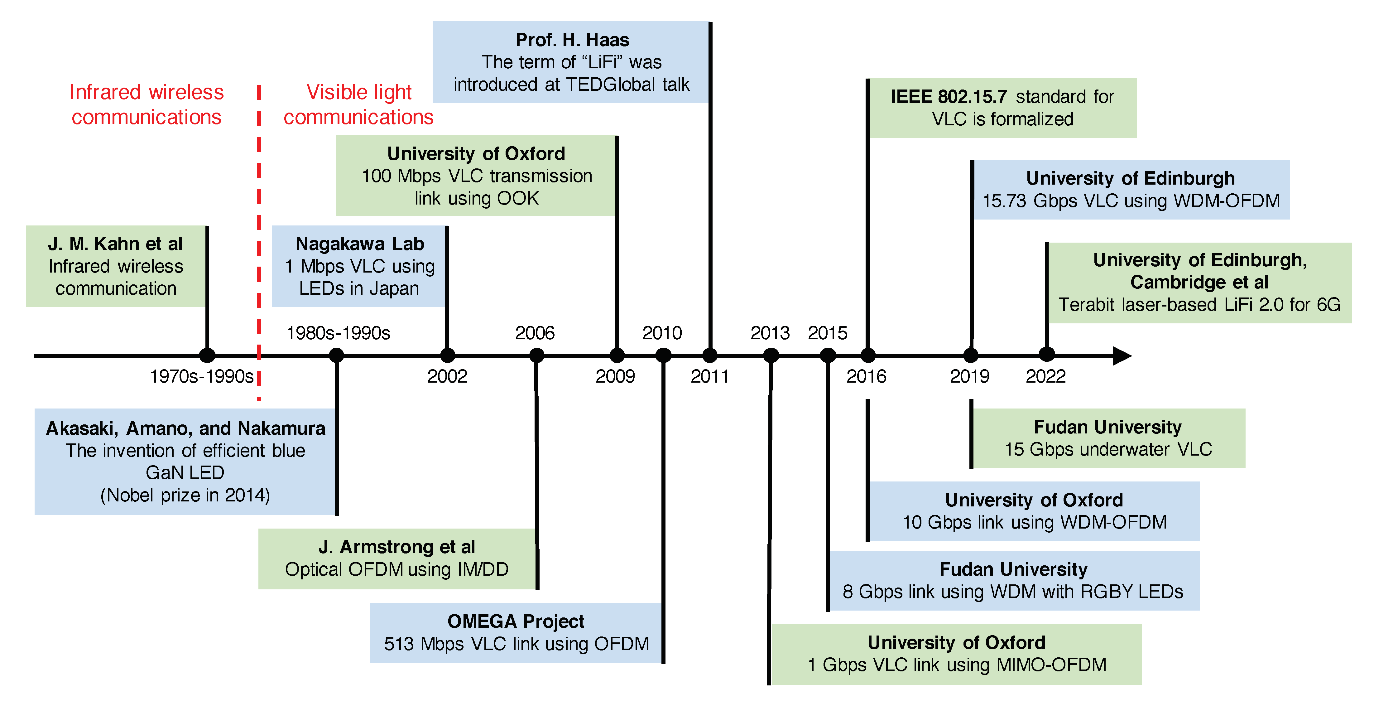
Figure 3.
The achieved VLC transmission data rates using different types of LED in the past 20 years. The curved lines illustrate a coarse representation of the data rates achieved over different years.
Figure 3.
The achieved VLC transmission data rates using different types of LED in the past 20 years. The curved lines illustrate a coarse representation of the data rates achieved over different years.

Figure 4.
Different types of white LED: (a) multi-chip RGB LED (b) phosphor-based LED.

Figure 5.
The radiation pattern of LEDs with different Lambertian orders (a) m = 1 (), (b) m = 2 (), (c) m = 5 (), and (d) m = 20 ().
Figure 5.
The radiation pattern of LEDs with different Lambertian orders (a) m = 1 (), (b) m = 2 (), (c) m = 5 (), and (d) m = 20 ().
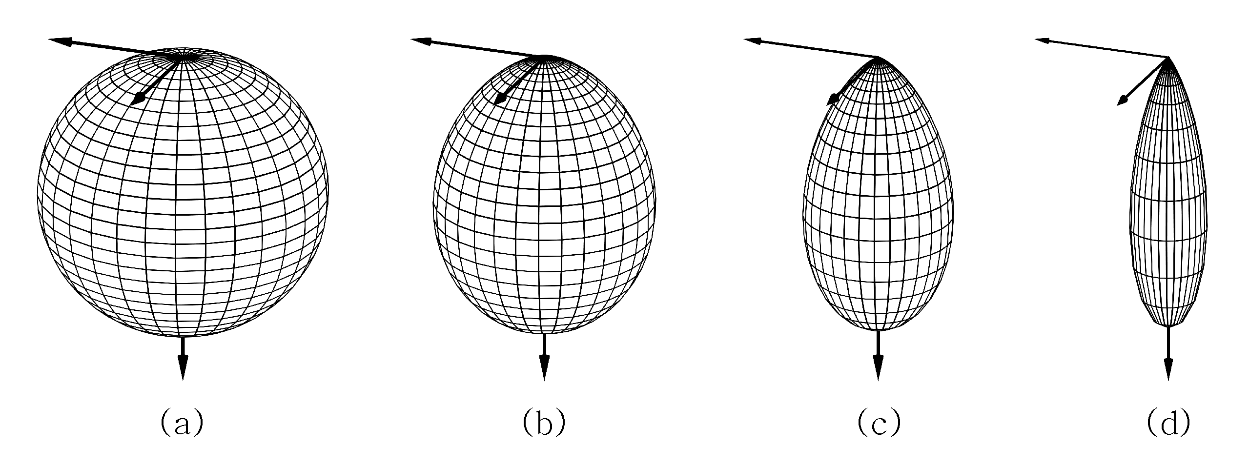
Figure 6.
The illumination level distribution (in lx) in a 10 m by 6 m room with 13 LED luminaires.

Figure 7.
A typical VLC receiver consists of an optical filter, an optical concentrator, and a photodiode.
Figure 7.
A typical VLC receiver consists of an optical filter, an optical concentrator, and a photodiode.
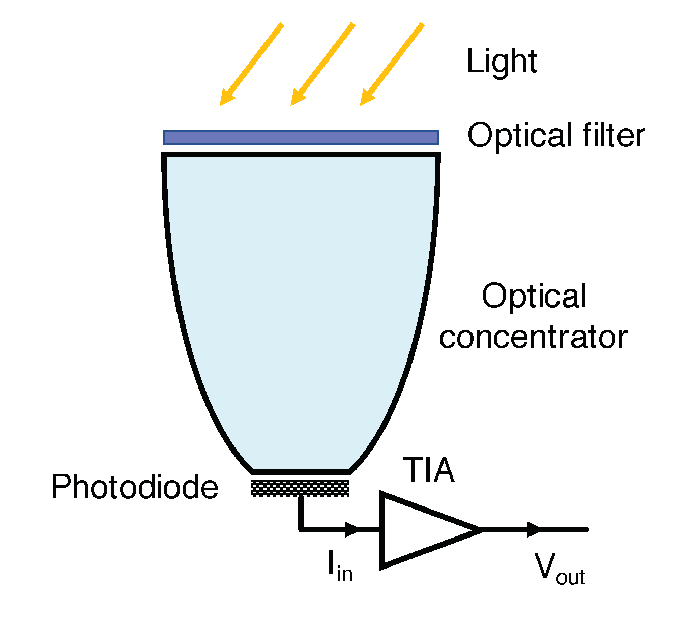
Figure 9.
The simulation trials of the photon detection process with the influence of the SPAD’s dead time (45 ns) considering a single microcell within a SiPM 30035 chip when the received irradiance levels are (a) 1 , (b) 10 , and (c) 100 . In these figures, the green circles indicate the time of detected photons and the blue lines indicate the associated dead time. The red crosses indicate the missed photons.
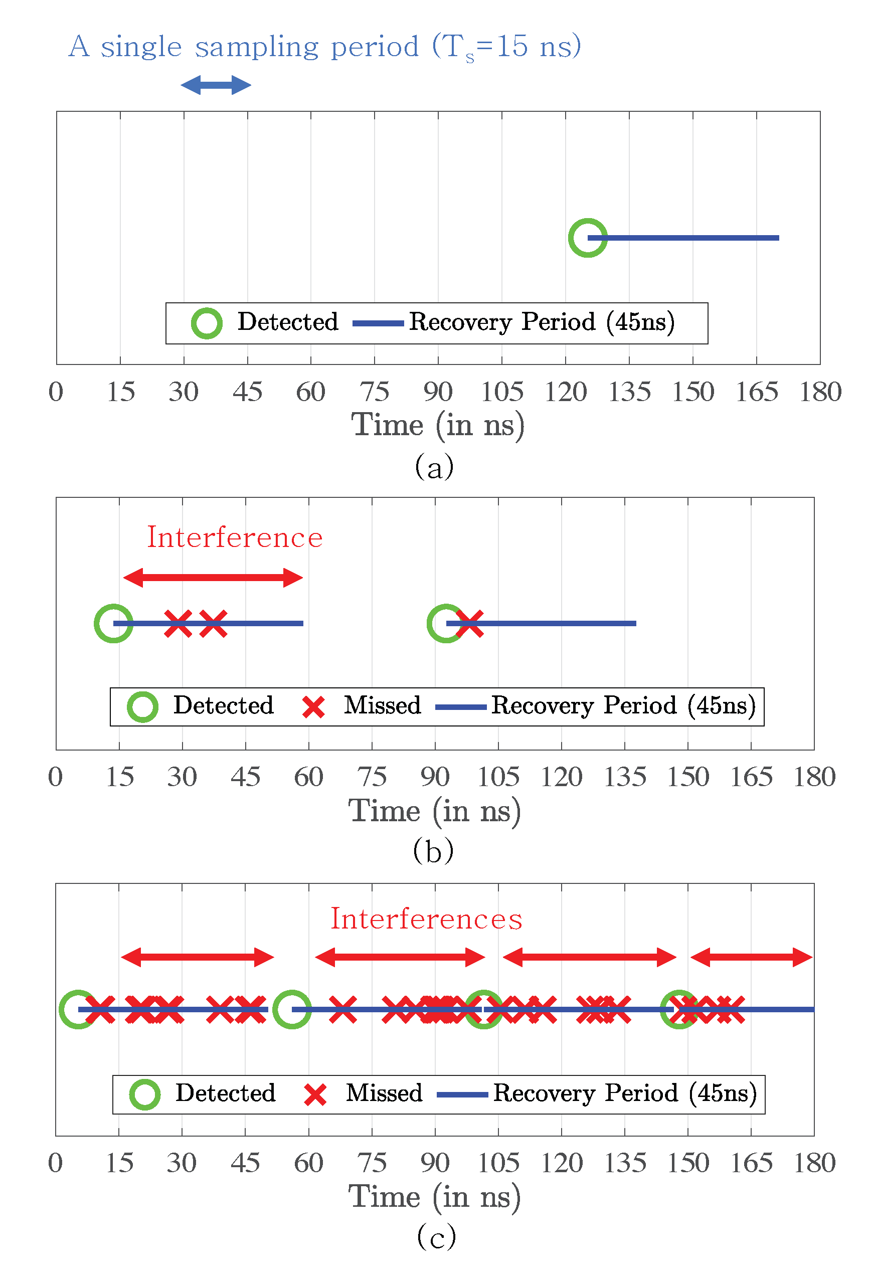
Figure 10.
The simulated nonlinear response of the SiPM chip 30035 and the desired linear response.

Figure 11.
Three typical optical MIMO systems considered in VLC: (a) spatial multiplexing, (b) spatial modulation, and (c) indoor optical cellular system.
Figure 11.
Three typical optical MIMO systems considered in VLC: (a) spatial multiplexing, (b) spatial modulation, and (c) indoor optical cellular system.
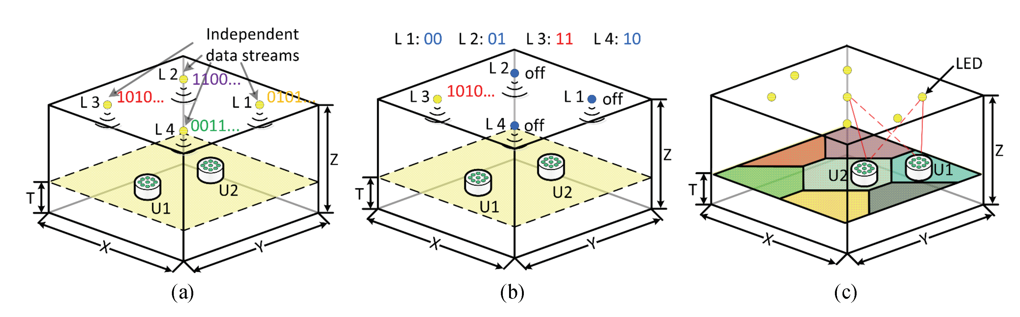
Figure 12.
Optical channel between multiple LED transmitters and multiple photodetectors.
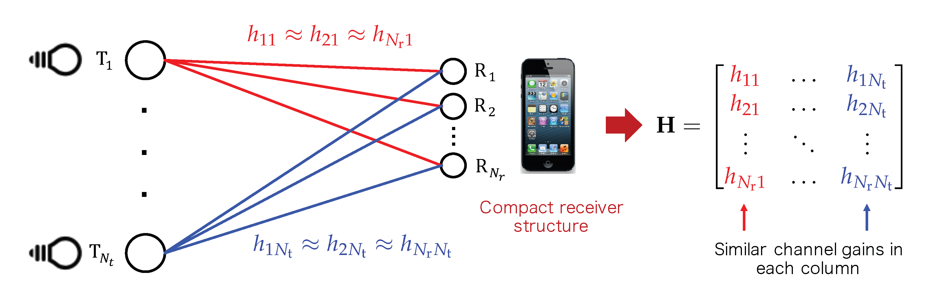
Figure 13.
Different types of optical MIMO receivers: (a) an imaging-lens-based receiver, (b) a hemispherical-lens-based receiver, (c) a receiver using PDs facing different directions, (d) a prism-based receiver, and (e) the angular diversity aperture (ADA) receiver.
Figure 13.
Different types of optical MIMO receivers: (a) an imaging-lens-based receiver, (b) a hemispherical-lens-based receiver, (c) a receiver using PDs facing different directions, (d) a prism-based receiver, and (e) the angular diversity aperture (ADA) receiver.
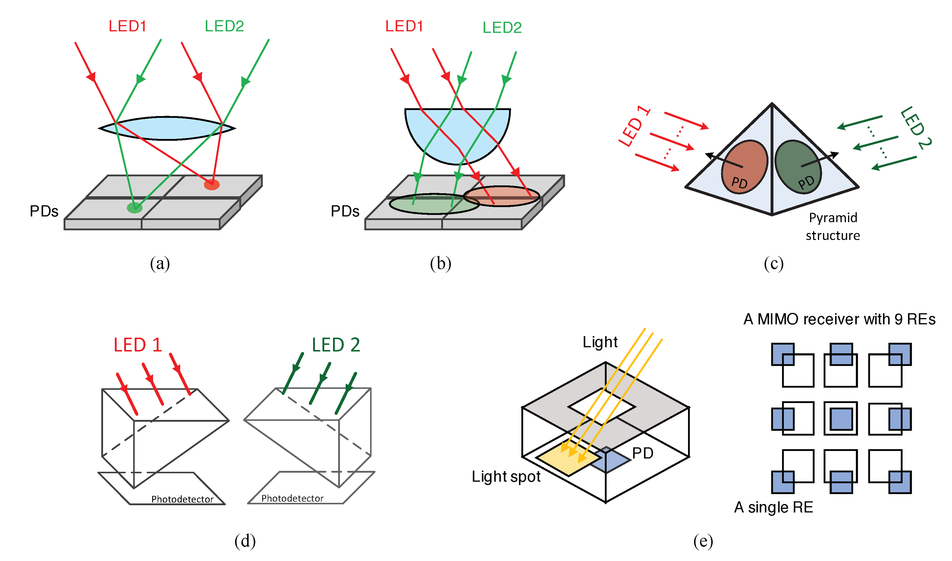
Figure 14.
The receiving pattern of an ADA receiver with nine REs: (a) the 3D optical channel gain plot and (b) the polar plot.
Figure 14.
The receiving pattern of an ADA receiver with nine REs: (a) the 3D optical channel gain plot and (b) the polar plot.


Table 1.
Phosphor-based white LED-based VLC links.
| Year | Transmitter | Receiver | Modulation | Multiplexing | Distance | Data Rate | Ref. |
|---|---|---|---|---|---|---|---|
| 2020 | white LED | PIN | DMT | - | 1 m | 3 Gbps | [24] |
| 2018 | white LED | SPAD | OOK | - | 1.2 km | 2 Mbps | [25] |
| 2015 | white LED | PIN | OFDM | - | 1.5 m | 2 Gbps | [26] |
| 2015 | white LED | PIN | OFDM | - | 1 m | 1.6 Gbps | [27] |
| 2013 | white LED | PIN | OFDM | MIMO | 1 m | 1.1 Gbps | [13] |
| 2012 | white LED | PIN | CAP | - | 0.23 m | 1.1 Gbps | [28] |
| 2012 | white LED | APD | DMT | - | 0.1 m | 1 Gbps | [29] |
| 2010 | white LED | APD | DMT | - | 0.3 m | 513 Mbps | [10] |
| 2009 | white LED | PIN | OOK | - | 0.1 m | 100 Mbps | [5] |
| 2007 | white LED | PIN | OFDM | - | 0.01 m | 100 Mbps | [30] |
| 2006 | white LED | PIN | OFDM | - | 1 m | 16 Kbps | [31] |
| 2002 | white LED | PIN | BPSK | - | - | 1 Mbps | [32] |
Table 2.
Multi-chip LED-based VLC links.
| Year | Transmitter | Receiver | Modulation | Multiplexing | Distance | Data Rate | Ref. |
|---|---|---|---|---|---|---|---|
| 2021 | 16 Si-LEDs | PIN | DMT | WDM | 1.2 m | 24.25 Gbps | [33] |
| 2019 | RGBY LEDs | PIN | OFDM | WDM | 1.6 m | 15.73 Gbps | [16] |
| 2019 | RGBYC Si-LEDs | PIN | DMT | WDM | 1.2 m | 15.17 Gbps | [17] |
| 2017 | RGB LEDs | PIN | OFDM | WDM + MIMO | 1 m | 6.36 Gbps | [34] |
| 2016 | RGB LEDs | SPAD | OFDM | WDM | 2 m | 60 Mbps | [35] |
| 2015 | RGBY LEDs | PIN | CAP | WDM | 1 m | 8 Gbps | [14] |
| 2015 | RGB LEDs | PIN | CAP | WDM | 1.5 m | 4.5 Gbps | [36] |
| 2014 | RGB LEDs | APD | OFDM | WDM | 0.01 m | 4.22 Gbps | [37] |
| 2012 | RGB LEDs | APD | OFDM | WDM | 0.1 m | 3.4 Gbps | [38] |
| 2012 | RGB LEDs | APD | DMT | WDM | 0.1 m | 1.25 Gbps | [39] |
Table 3.
LED-based VLC links.
| Year | Transmitter | Receiver | Modulation | Multiplexing | Distance | Data Rate | Ref. |
|---|---|---|---|---|---|---|---|
| 2023 | LED | APD | OFDM | - | 0.31 m | 3.5 Gbps | [40] |
| 2022 | LED | APD | OFDM | WDM | 0.25 | 18.43 Gbps | [41] |
| 2021 | LED | APD | OFDM | - | 0.25 | 4.343 Gbps | [42] |
| 2017 | LED | PIN | OFDM | - | 0.275 m | 11.12 Gbps | [43] |
| 2016 | LEDs | PIN | OFDM | WDM | 1.5 m | 10 Gbps | [15] |
| 2016 | LED | APD | PAM-4 | MIMO | 0.5 m | 7.5 Gbps | [44] |
| 2016 | LED | PIN | OFDM | - | 0.75 m | 5.37 Gbps | [45] |
| 2015 | LED | APD | OFDM | WDM | - | 2.3 Gbps | [46] |
| 2014 | LED | PIN | OFDM | - | 0.05 m | 3 Gbps | [47] |
| 2014 | LED | APD | OFDM | - | 0.03m | 1.68 Gbps | [48] |
| 2011 | LED | PIN | OOK | - | - | 512 Mbps | [49] |
| 2010 | LED | PIN | OOK | - | - | 1 Gbps | [50] |
Disclaimer/Publisher’s Note: The statements, opinions and data contained in all publications are solely those of the individual author(s) and contributor(s) and not of MDPI and/or the editor(s). MDPI and/or the editor(s) disclaim responsibility for any injury to people or property resulting from any ideas, methods, instructions or products referred to in the content. |
© 2023 by the authors. Licensee MDPI, Basel, Switzerland. This article is an open access article distributed under the terms and conditions of the Creative Commons Attribution (CC BY) license (https://creativecommons.org/licenses/by/4.0/).
Share and Cite
MDPI and ACS Style
He, C.; Chen, C. A Review of Advanced Transceiver Technologies in Visible Light Communications. Photonics 2023, 10, 648. https://doi.org/10.3390/photonics10060648
AMA Style
He C, Chen C. A Review of Advanced Transceiver Technologies in Visible Light Communications. Photonics. 2023; 10(6):648. https://doi.org/10.3390/photonics10060648
Chicago/Turabian StyleHe, Cuiwei, and Chen Chen. 2023. "A Review of Advanced Transceiver Technologies in Visible Light Communications" Photonics 10, no. 6: 648. https://doi.org/10.3390/photonics10060648
Note that from the first issue of 2016, this journal uses article numbers instead of page numbers. See further details here.