The Design of a Photonic Crystal Fiber for Hydrogen Cyanide Gas Detection


1
Faculty of Electrical and Computer Engineering, University of Tabriz, Tabriz 51664, Iran
2
College of Engineering, Design and Physical Sciences, Brunel University London, Uxbridge UB8 3PH, UK
*
Authors to whom correspondence should be addressed.
Photonics 2024, 11(2), 178; https://doi.org/10.3390/photonics11020178
Submission received: 27 November 2023
/
Revised: 18 January 2024
/
Accepted: 7 February 2024
/
Published: 16 February 2024
(This article belongs to the Special Issue Advanced Photonic Sensing and Measurement II)
Abstract
:Hydrogen cyanide gas is a dangerous and fatal gas that is one of the causes of air pollution in the environment. A small percentage of this gas causes poisoning and eventually death. In this paper, a new PCF is designed that offers high sensitivity and low confinement loss in the absorption wavelength of hydrogen cyanide gas. The proposed structure consists of circular layers that are located around the core, which is also composed of circular microstructures. The finite element method (FEM) is used to simulate the results. According to the results, the PCF gives a high relative sensitivity of 65.13% and a low confinement loss of 1.5 × 10⁻³ dB/m at a wavelength of 1.533 µm. The impact of increasing the concentration of hydrogen cyanide gas on the relative sensitivity and confinement loss is investigated. The high sensitivity and low confinement losses of the designed PCF show that this optical structure could be a good candidate for the detection of this gas in industrial and medical environments.
1. Introduction
Air pollution occurs due to the entry of various harmful particles, such as gases and biomolecules, into the atmosphere. The continuous release of various chemical pollutants, such as NOx, NH3, CH4, SOx, CO, and fluorocarbons, from industrial emissions, vehicle exhausts, and household waste into the environment causes many problems. These problems include acid rain, global warming, sick house syndrome, and ozone layer destruction [1]. Hydrogen cyanide gas (HCN) is a toxic gas produced by burning materials. This gas is fatal and may cause death. This gas is present in many different combustion sources, such as cigarette or car smoke. Since this gas has a low boiling point, high-sensitivity sensors should be used to detect it [2].
Small amounts of HCN can be found in the human body due to endogenous biological processes; it may originate from endogenous production, bacteria, or the ingestion of food containing HCN [3]. From a medical point of view, HCN can also be produced in substantial amounts through the colonization of special types of bacteria in the airways, which results in cystic fibrosis and an inability to effectively defend the airways from infections [4]. It is, therefore, important to detect bacterial infections in the airways as early as possible. However, current diagnostic techniques lack sensitivity (cough swabs), are very invasive (bronchoalveolar lavage (BAL)), and commonly miss early infections, especially in young children. An attractive noninvasive and fast medical diagnostic method is a breath analysis, and HCN seems to be a promising indicator for bacterial detection in the lungs [5].
Many electrical and optical sensors have been proposed to detect toxic gases; however, optical sensors are used more due to their higher sensitivity, longer lifespan, and immunity to magnetic interferences [6,7,8,9,10].
A new generation of optical fibers, called photonic crystal fibers (PCFs), are widely used in the detection of gases/liquids due to their unique properties. According to the guiding mechanism, PCFs can be divided into two categories: photonic bandgap (PBG) fibers [11,12] and index guiding fibers [13,14].
Some previously reported works have detected toxic gases, such as HCN, using PCF. In [15], a hexagonal ring core and cladding PCF is proposed. In order to study the reliability of the designed structure as a terahertz gas sensor, the detection of HCN in the gas phase is analyzed. The propagation loss of the structure is 0.013 dB/m. When the air holes in the core area are filled with HCN at a certain concentration, a clear transmittance drop at 1.24 THz is observed. The photon energies of molecules falling correctly into the terahertz region offer a high potential for gas detection. However, detecting gas at low concentrations is difficult because of the weak dipole moments of gas in the terahertz region. In [16], saturated absorption is studied in the overtone transitions of acetylene and HCN molecules confined in the hollow core of a photonic bandgap fiber. The results show the observation of saturated absorption in both samples at 1537.300409 nm, which has an overlap with the optical communication C-band, realizing the full potential of the fibers in optical communication. In [17], a micro-cored photonic-crystal-fiber-based gas sensor for detecting colorless or toxic gasses is reported. The core area is made up of eight horizontally arranged elliptical holes. Five hexagonal rings surround the core region as cladding. The relative sensitivity and confinement loss are 53% and 3.21 × 10⁻⁶ dB/m, respectively, at the wavelength of λ = 1.33 μm. In [18], a PCF-based chemical sensor is proposed, which has a high relative sensitivity and low confinement loss across a wide range of wavelengths, from 0.6 μm to 2 μm. The structure consists of five rings of porous cladding and two rings of porous core. The outcomes show that the sensitivity and confinement loss are 60.57% and 8.7 × 10⁻⁸ dB/m at 1.33 µm for water and benzene analyte. In [19], a hexagonal PCF for sensing toxic gases is presented. The structure is made up of six hexagonal rings for cladding and one circular ring in the core area. The core and cladding regions are detached, with four noncircular quarter sectors. The relative sensitivity and confinement loss are 67.07% and 8.61 × 10⁻⁵ dB/m, respectively, at the wavelength of λ = 1.578 μm. In [20], a gas sensor for detecting ammonia in human exhaled breath is presented, which may help diagnose renal disease. The PCF-based sensor has five hexagonal rings for cladding and two circular rings in the core. The simulation outcomes indicated that the relative sensitivity and confinement loss are 63% and 1.98 × 10⁻⁴ dB/m, respectively, at the wavelength of λ = 1.544 μm. In [21], the designed toxic gas sensor structure consists of air holes around the core, with a so-called quasi-crystalline arrangement. The relative sensitivity and confinement loss are near 50% and 2.1 × 10⁻⁶ dB/m at 1.55 µm. In [22], a PCF with two rings of circular lattice air holes in the core and five rings of hexagonal lattice air holes in the cladding region is reported. The numerical results for the proposed model show that at a wavelength of 1.33 μm, the relative sensitivity and confinement loss are 44.47% and 1.8310−8 dB/m for an absorption line of methane and hydrogen fluoride gases. In [23], a PCF-based CO gas sensor is designed to detect hyperbilirubinemia levels in humans via breath analysis. The suggested structure has five hexagonal rings in the cladding. Also, circular and elliptical holes are placed in the core. The relative sensitivity and confinement loss are 64% and 3.8 × 10⁻³ dB/m, respectively, at the wavelength of λ = 1.567 μm. In [24], the designed sensor has two circular rings of elliptical holes in the core area and two hexagonal rings of vertical/horizontal elliptical holes in the cladding. The elliptical form of the core allows gas and light to interact well, resulting in increased sensitivity. A sensitivity of 65.86% is achieved at 1 μm for C10H16. Also, the attenuation is 2.32 × 10⁻³ at this wavelength. It is clear that the designed structure has a complicated geometry. In [25], the authors proposed a compact, cost-effective, and infrared-laser-based sensor for detecting hydrogen cyanide (HCN) in exhaled breath within seconds. In [26], a highly sensitive and selective detection method is proposed, using photonic crystal cavity defect mode with resonance tailored to the characteristic absorption peak of the target gas specimen. In [27], a 10 GHz, 1.55 μm mode-locked fiber laser is reported, in which the optical frequency is stabilized to an HCN absorption line. This laser has an optical frequency stability of 5 × 10⁻¹¹ for an integration time of 1 s.
In this article, we design a new structure of PCF that has high sensitivity and low confinement loss in the absorption wavelength of HCN gas. The impacts of increasing the concentration of HCN gas on the relative sensitivity and confinement loss, as well as the coupling efficiency of the structure, are investigated.
2. Proposed PCF-Based Geometrics
Figure 1 shows a cross-sectional image of the proposed structure. The geometry of the designed PCF structure consists of five layers of circular holes in the cladding region, the diameter of which is defined by the d parameter. The core region consists of three circular layers surrounding the bigger central hole. The diameters of core holes from the outside to the inside are d1, d2, d3, and d4. The distance between one hole and the next hole is called the pitch and is denoted by Λ. The refractive index of air is 1, and the refractive index of silica, which is located in the background area of the fiber, is 1.45. The Perfectly Matched Layer (PML) has been used as a boundary condition to eliminate electromagnetic noise. The size of PML is 10% of the size of the whole PCF. It is clear that the performance of the PCF is directly influenced by the geometric dimensions and how the holes are arranged in the core and cladding areas. The parameters of the core region have a significant effect on the relative sensitivity. The changes in the holes in the cladding area have the greatest impact on the confinement losses. In order to obtain the desired structure, parametric studies and numerous simulations have been performed. After reviewing and summarizing the results, the parameters presented in Table 1 have been selected as the final geometry. As is clear from Table 1, the holes in the core area gradually get bigger. As a result, the amount of optical power in the center of the PCF increases, and the interaction of light with the sample gas increases. Eventually, the relative sensitivity increases. The holes in the cladding area are larger than the holes in the core area, which reduces confinement loss.
3. Essential Equations for PCF Characteristics
An important parameter in PCFs is the calculation of confinement loss. The loss of fibers is related to the imaginary part of the refractive index. When light leaks from the core to the cladding area, the value of this parameter increases. Therefore, to reduce this parameter, it is necessary to trap the light inside the core. The following equation is used to calculate this parameter [28]:
where Im[neff] is the imaginary part of the effective refractive index, and k0 is the wave number in the vacuum. Another important feature of PCFs is relative sensitivity. To evaluate how effectively the proposed sensor detects samples, this parameter is calculated. The value of this parameter is derived from the famous Beer–Lambert law, which is the following equation [28]:
where I(λ) and I0(λ) are the light intensity after and before hitting the material, αm is the gas absorption coefficient, l is the length of the light path in the material, and c is the concentration of the sample. This law states that the concentration of gas or liquid in a solution can be determined by knowing the amount of light passing through, the length of the path, and the chemical nature of that gas/liquid. The r parameter in this equation is the relative sensitivity, which is obtained through the following equation [28]:
In this equation, Re[neff] is the real part of the effective mode index; ns is the refractive index of the target gas. The coefficient f is obtained by calculating the ratio of the light power inside the holes to the light power along the entire fiber. To obtain the power from the electric and magnetic fields along the x and y axes, it is integrated as the following equation [28]:
where Ex, Ey and Hx, Hy are the electric and magnetic fields along the horizontal and vertical axis, respectively. In the fundamental mode of PCFs, light is trapped inside the core region. Therefore, the electric field distribution is maximized in this area and increases the relative sensitivity.
The effective area of a PCF is an effective measure of the area that is trapped during propagation inside the fiber in the original mode. The effective area is a concept that originates from the theory of third-order nonlinear effects in optical waveguides. The parameter of the effective area is obtained from the following formula [28]:
where E is the electric field along the entire length of the fiber.
The concept of numerical aperture (NA) in fibers should be investigated to calculate the power efficiency. Unlike an index-guided PCF, the fibers conduct light using a photonic or bandgap mechanism instead of a total internal reflection mechanism. According to the fiber geometry and the input wavelength, we can determine the wave number k supported in the fibers. Then, the largest angle Ѳmax between k and the z-axis of the fiber determines the value of NA, which is equal to sin(Ѳmax) [23]. The guiding region including all the supported wavenumbers is a solid angle, and we refer to it as a guiding solid angle. On the other hand, the inserted fiber tip with a thinner cladding places the light source inside the hollow core. For simplicity, it can be considered as a point light source from the perspective of the far-field plane. Likewise, the solid angle consisting of all wavenumbers radiated from the tip of the SMF is called the divergence solid angle (DSA). The power in the cross-section can be coupled from the SMF tip to the fibers. The efficiency of the f-couple can be simply expressed as follows:
where PDSA is the total power radiated from the fiber tip, while PDSA∩GSA is the power in the intersection region that can be collected by the PCF [23].
4. Simulation Results and Discussion
The simulation is conducted in commercial multi-physics software COMSOL 6.1. This software solves problems using the finite element method (FEM), which is a reliable method. The triangular type is used for meshing operations. The size of maximum and minimum meshes are 0.3 and 0.006 µm. The value of the curvature factor is 0.3. The degree number of freedom for this fiber is solved with 469,827 meshes. Figure 2a,b show a 2D view of the fundamental mode electric field distribution in the entire and core areas at the 1.533 μm wavelength, respectively. The 3D view is illustrated in Figure 2c. This operation wavelength is selected according to the absorption spectrum of the HCN gas [16]. In this case, the designed structure will be compatible with the conventional optical communication fibers in C-band. Meanwhile, the extrinsic attenuation is minimal in this band and could be applicable for distributed sensing topologies. According to Figure 2, the major part of the field is confined to the core region. So, the optical field will have more interaction with the sample gas inserted in the innermost hole. A high relative sensitivity of 65.13% is calculated at this wavelength. Also, the results show that the confinement loss and birefringence coefficient are 1.5 × 10⁻³ dB/m and 1.02 × 10⁻³, respectively, at the 1.533 μm wavelength. The effective refractive index (neff) of PCF depends not only on the operating wavelength but also on the propagation mode of the PCF.
Figure 3a shows the effect of wavelength variation on the relative sensitivity of the designed structure. As can be seen, with increasing wavelength, the relative sensitivity increases. Figure 3b shows the effect of wavelength changes on confinement loss. With the increase in the wavelength, the confinement loss is also increased. Figure 3c shows the effective area of the proposed PCF as a function of wavelength changes. This figure shows that as the wavelength increases, the effective area increases due to the field expansion to the outer areas of the fiber. All these outcomes are explainable by studying the behavior of the real and imaginary parts of neff due to wavelength variations.
The real and imaginary parts of the neff variations due to the wavelength are illustrated in Figure 4. According to the equations presented in Section 3, these parameters have a direct impact on the relative sensitivity and confinement loss behavior of the optical structure. The real part of neff is presented with a dashed line. It is clear that Re[neff] is approximately constant in the 1.3 μm to 1.7 μm interval and has a rare descent manner. Eventually, it causes the relative sensitivity to have a small ascend behavior due to wavelength increasing. It is conceivable that the f parameter in Equation (3) is related to the field distribution manner, which itself depends on neff too.
Im[neff] has a direct impact on the confinement loss. By calculating the Equation (1) derivative,
it is obvious that owing to the sharp slope of Im[neff], the wavelength variation will have a sensible effect on the confinement loss. Furthermore, decreasing the effective refractive index causes the optical field to spread in the cladding region. Eventually, loss increase occurs.
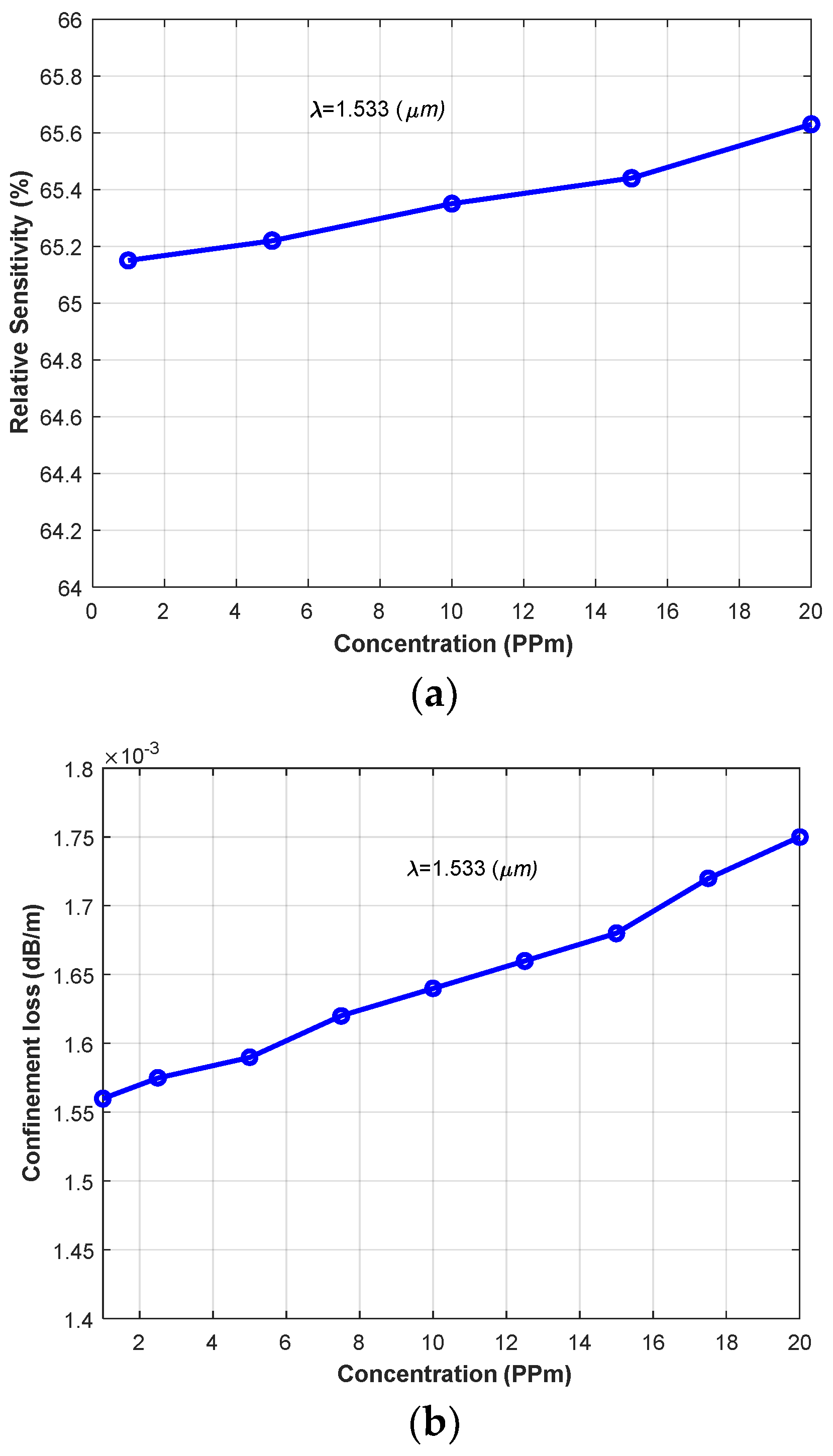
Figure 5a,b show the effect of the hydrogen cyanide gas concentration on the relative sensitivity and confinement loss for concentrations from 0 ppm to 20 ppm at the wavelength of 1.553 µm. The theoretical basis for relating refractive index to density is embedded in the state equation of electromagnetic polarization. As the electromagnetic wave travels through a medium, the wave’s phase velocity changes proportionally to the refractive index of the substance. The end result is the so-called Lorentz–Lorenz equation relating the refractive index to molecular molar density. The Lorentz–Lorenz equation applies to an isotropic system containing nonpolar substances with no molecular interactions [29]. To model the density effect on the HCN gas, the heat transfer module has been added to the physics of the problem. The refractive index of different gas concentrations is estimated. The pressure and temperature are assumed to be 1 atm and 25 °C, respectively. As can be seen, by increasing the concentration of this gas, the relative sensitivity is also enhanced. Figure 5b also shows that as the concentration of this gas increases, confinement losses will also increase. The relative sensitivities for concentrations of 1 ppm, 5 ppm, 10 ppm, 15 ppm, and 20 ppm are equal to 65.17%, 65.22%, 65.38%, 65.42%, and 65.61%.
The designed structure has seven modes according to Figure 6. The only guided mode is the fundamental mode (mode 1), and the other modes are radiation. It is clear that, only in the fundamental mode, the light is trapped in the core region owing to the low confinement loss. Meanwhile, other modes are evanescent and cladding scattering. So, higher-order modes do not affect the sensing mechanism.
Figure 7 shows the optimal coupling power percentage values for the different proposed fiber modes. As can be seen, the fundamental mode has the highest power coupling efficiency.
As mentioned in the Introduction section, one of the important and interesting advantages of optical sensors is safety against magnetic noise. To check the resistance of the proposed structure against magnetic field waves, a horizontal and vertical magnetic field of 0.1 tesla is applied to the fiber at a distance of 10 µm. From Figure 8, it is clear that the created field dampens when it reaches the fiber. Therefore, we conclude that the proposed fiber is immune to the magnetic fields of the environment.
Table 2 presents the difference between the characteristics of the proposed PCF and the previously presented PCFs. The article presented in [19] has a higher sensitivity, which is obtained at the cost of complexity in the core area and the placement of non-circular and non-elliptical holes. The proposed structure has high sensitivity and suitable loss performance with a simple circular ring arrangement.
Figure 9 shows the practical implementation steps of the proposed sensor. The broadband light is passed through a monochromator (MC) to produce a light beam with a specific wavelength. The light is connected to the proposed PCF through a single-mode fiber (SMF). It is recommended that the fiber size of the SMF core area be the same as the core area of the proposed fiber so that maximum light is transmitted only to the core area. The detector converts light to current, and finally, it will be displayed on the PC.
With regard to the fabrication technology for photonic crystal fibers, a variety of methods have been employed. Essentially, there are two approaches to the synthesis of photonic crystals: the top-down method and the bottom-up method. In the former method, silicon technology, based on lithography and etching, is central, and in the latter, the sol–gel method is most commonly employed, where the control of chemical reactions in a liquid-phase system is essential. Silicon technology has great advantages and allows the creation of photonic crystal fibers with an exactly desired geometry on a sub-micrometer scale. However, it simultaneously has a problem of high production costs. The sol–gel process, on the other hand, also has great advantages, particularly concerning the easy fabrication of material into any shape, tiny size, easy control of composition, and low processing cost, though this process generally has a significant problem in which microstructures produced often have less precise dimensions due to, for instance, the considerable shrinkage of the precursor material during drying and/or sintering [30]. The stack and draw process is generally preferable for honeycomb and triangular lattices. It has some limitations in constructing a circular pattern [31]. So, it seems that the sol–gel method is more suitable for the proposed structure due to its flexibility in making all kinds of circular holes and microstructures. Meanwhile, fabrication errors would be inevitable in the case of the sol–gel fabrication method. Therefore, the optical propagation characteristics of the proposed structure must be sufficiently resistant against these errors.
The proposed and designed structure is in the simulation and performance evaluation phase. It is clear that in the next step, environmental effects, such as temperature and pressure, on the performance of the sensor should be investigated and evaluated. We have tried to develop new methods of analysis of the exhaled gas for the aim of noninvasive disease diagnosis. As mentioned in the introduction, hydrogen cyanide gas can be used as a biomarker in the diagnosis of some respiratory diseases. Therefore, in future works, we will focus on the simulation of temperature and humidity conditions and the combination of exhaled gas.
5. Conclusions
In this paper, a new PCF gas sensor is designed to detect hydrogen cyanide gas. This gas is very toxic and fatal. Increasing the amount of this gas in the universe can threaten the lives of thousands of people. The methods that had been proposed for detecting this gas were mostly based on electronic devices. However, there are a series of disadvantages, such as a short life span, low sensitivity, sensitivity to temperature and pressure changes, being expensive, and a lack of immunity to the magnetic field for these devices. On the other hand, optical sensors have many advantages, such as high sensitivity, longer life, higher selectivity, less sensitivity to temperature and pressure changes, and immunity to magnetic fields. The simulation outcomes indicate that the proposed PCF gives high sensitivity and low confinement loss at the wavelength of 1.533 µm, which is adequate with the hydrogen cyanide gas absorption line. The results show that the designed PCF gives a relative sensitivity of 65.13% and a confinement loss of 1.5 × 10⁻³ dB/m. Furthermore, by increasing the concentration of hydrogen cyanide gas, the relative sensitivity is increased. Therefore, these concepts show that the designed PCF can be used for detecting this gas in medical and industrial applications.
Author Contributions
Conceptualization, A.P.F. and S.M.; methodology, A.P.F.; software, A.P.F.; validation, S.M., S.D. and M.D.; investigation, A.P.F.; writing—original draft preparation, A.P.F.; writing—review and editing, S.M.; supervision, S.M. and S.D.; project administration, S.M. All authors have read and agreed to the published version of the manuscript.
Funding
This research received no external funding.
Institutional Review Board Statement
Not applicable.
Informed Consent Statement
Not applicable.
Data Availability Statement
Data are contained within the article.
Conflicts of Interest
The authors declare no conflicts of interest.
References
- Kawasaki, H.; Ueda, T.; Suda, Y.; Ohshima, T. Properties of metal doped tungsten oxide thin films for NOx gas sensors grown by PLD method combined with sputtering process. Sens. Actuators B Chem. 2004, 100, 266–269. [Google Scholar] [CrossRef]
- Walia, G.K.; Randhawa, D.K.K. Density-functional study of hydrogen cyanide adsorption on silicene nanoribbons. J. Mol. Model. 2018, 24, 242. [Google Scholar] [CrossRef]
- Siegien, I.; Bogatek, R. Cyanide action in plants—From toxic to regulatory. Acta Physiol. 2006, 28, 483–497. [Google Scholar] [CrossRef]
- Enderby, B.; Smith, D.; Carroll, W.; Lenney, W. Hydrogen cyanide as a biomarker for Pseudomonas aeruginosa in the breath of children with cystic fibrosis. Pediatr. Pulmonol. 2009, 44, 142–147. [Google Scholar] [CrossRef]
- Arslanov, D.D.; Castro, M.P.P.; Creemers, N.A.; Neerincx, A.H.; Spunei, M.; Mandon, J.; Cristescu, S.M.; Merkus, P.; Harren, F.J.M. Optical parametric oscillator-based photoacoustic detection of hydrogen cyanide for biomedical applications. J. Biomed. Opt. 2013, 18, 107002. [Google Scholar] [CrossRef]
- Arroyo, P.; Gómez-Suárez, J.; Herrero, J.L.; Lozano, J. Electrochemical gas sensing module combined with Unmanned Aerial Vehicles for air quality monitoring. Sens. Actuators B Chem. 2022, 364, 131815. [Google Scholar] [CrossRef]
- Kaaliveetil, S.; Yang, J.; Alssaidy, S.; Li, Z.; Cheng, Y.-H.; Menon, N.H.; Chande, C.; Basuray, S. Microfluidic Gas Sensors: Detection Principle and Applications. Micromachines 2022, 13, 1716. [Google Scholar] [CrossRef] [PubMed]
- Isaac, N.A.; Pikaar, I.; Biskos, G. Metal oxide semiconducting nanomaterials for air quality gas sensors: Operating principles, performance, and synthesis techniques. Microchim. Acta 2022, 189, 196. [Google Scholar] [CrossRef] [PubMed]
- Kumar, N.; Suthar, B.; Nayak, C.; Bhargava, A. Analysis of a gas sensor based on one-dimensional photonic crystal structure with a designed defect cavity. Phys. Scr. 2023, 98, 065506. [Google Scholar] [CrossRef]
- Hodgkinson, J.; Tatam, R.P. Optical gas sensing: A review. Meas. Sci. Technol. 2012, 24, 012004. [Google Scholar] [CrossRef]
- Knight, J.C.; Broeng, J.; Birks, T.A.; Russell, P.S.J. Photonic band gap guidance in optical fibers. Science 1998, 282, 1476–1478. [Google Scholar] [CrossRef] [PubMed]
- Fini, J.M. Microstructure fibers for optical sensing in gasses and liquids. Meas. Sci. Technol. 2004, 15, 1120–1128. [Google Scholar] [CrossRef]
- Knight, J.C.; Birks, T.A.; Russell, P.S.J.; Atkin, D.M. All-silica single-mode optical fiber with photonic crystal cladding. Opt. Lett. 1996, 21, 1547–1549. [Google Scholar] [CrossRef] [PubMed]
- Birks, T.A.; Knight, J.C.; Russell, P.S.J. Endlessly single-mode photonic crystal fiber. Opt. Lett. 1997, 22, 961–963. [Google Scholar] [CrossRef] [PubMed]
- Qin, J.; Zhu, B.; Du, Y.; Han, Z. Terahertz detection of toxic gas using a photonic crystal fiber. Opt. Fiber Technol. 2019, 52, 101990. [Google Scholar] [CrossRef]
- Henningsen, J.; Hald, J.; Peterson, J.C. Saturated absorption in acetylene and hydrogen cyanide in hollow-core photonic bandgap fibers. Opt. Express 2005, 13, 10475–10482. [Google Scholar] [CrossRef] [PubMed]
- Asaduzzaman, S.; Ahmed, K. Proposal of a gas sensor with high sensitivity, birefringence and nonlinearity for air pollution monitoring. Sens. Bio-Sens. Res. 2016, 10, 20–26. [Google Scholar] [CrossRef]
- Chowdhury, S.; Sen, S.; Ahmed, K.; Paul, B.K.; Alam Miah, M.B.; Asaduzzaman, S.; Islam, S.; Islam, I. Porous shaped photonic crystal fiber with strong confinement field in sensing applications: Design and analysis. Sens. Bio-Sens. Res. 2017, 13, 63–69. [Google Scholar] [CrossRef]
- Fard, A.M.; Sarraf, M.J.; Khatib, F. Design and optimization of index guiding photonic crystal fiber-based gas sensor. Optik 2021, 232, 166448. [Google Scholar] [CrossRef]
- Abbaszadeh, A.; Makouei, S.; Meshgini, S. Ammonia measurement in exhaled human breath using PCF sensor for medical applications. Photonics Nanostruct. Fundam. Appl. 2021, 44, 100917. [Google Scholar] [CrossRef]
- Dashtban, Z.; Salehi, M.R.; Abiri, E. High sensitivity all-optical sensor for detecting toxic gases using hollow-core photonic crystal fiber composed of magnesium fluoride. Opt. Fiber Technol. 2022, 72, 102958. [Google Scholar] [CrossRef]
- Mishra, G.P.; Kumar, D.; Chaudhary, V.S.; Kumar, S. Design and sensitivity improvement of microstructured-core photonic crystal fiber based sensor for methane and hydrogen fluoride detection. IEEE Sens. J. 2021, 22, 1265–1272. [Google Scholar] [CrossRef]
- Mortazavi, S.; Makouei, S.; Garamaleki, S.M. Hollow core photonic crystal fiber based carbon monoxide sensor design applicable for hyperbilirubinemia diagnosis. Opt. Eng. 2023, 62, 066105. [Google Scholar] [CrossRef]
- Nizar, S.M.; Britto, E.C.; Michael, M.; Sagadevan, K. Photonic crystal fiber sensor structure with vertical and horizontal cladding for the detection of hazardous gases. Opt. Quantum Electron. 2023, 55, 1186. [Google Scholar] [CrossRef]
- Azhar, M.; Mandon, J.; Neerincx, A.H.; Liu, Z.; Mink, J.; Merkus, P.J.F.M.; Cristescu, S.M.; Harren, F.J.M. A widely tunable, near-infrared laser-based trace gas sensor for hydrogen cyanide (HCN) detection in exhaled breath. Appl. Phys. B Laser Opt. 2017, 123, 268. [Google Scholar] [CrossRef]
- Shi, X.; Zhao, Z.; Han, Z. Highly sensitive and selective gas sensing using the defect mode of a compact terahertz photonic crystal cavity. Sens. Actuators B Chem. 2018, 274, 188–193. [Google Scholar] [CrossRef]
- Yoshida, M.; Yoshida, K.; Kasai, K.; Nakazawa, M. 155 μm hydrogen cyanide optical frequency-stabilized and 10 GHz repetition-rate-stabilized mode-locked fiber laser. Opt. Express 2016, 24, 24287–24296. [Google Scholar] [CrossRef] [PubMed]
- Monro, T.M.; Belardi, W.; Furusawa, K.; Baggett, J.C.; Broderick, N.G.R.; Richardson, D.J. Sensing with microstructured optical fibres. Meas. Sci. Technol. 2001, 12, 854–858. [Google Scholar] [CrossRef]
- Wanstall, C.T.; Agrawal, A.K.; Bittle, J.A. Implications of real-gas behavior on refractive index calculations for optical diagnostics of fuel–air mixing at high pressures. Combust. Flame 2020, 214, 47–56. [Google Scholar] [CrossRef]
- Kuwabara, M. Photonic Crystals Fabricated by Sol-Gel Process, Handbook of Sol-Gel Science and Technology; Springer: Berlin/Heidelberg, Germany, 2018. [Google Scholar]
- Sun, X.H.; Tao, X.M.; Wang, Y.Y. Various photonic crystal structures fabricated by using a top-cut hexagonal prism. Appl. Phys. A 2010, 98, 255–261. [Google Scholar] [CrossRef]
Figure 1.
The geometry of the designed PCF.


Figure 2.
Electrical field distribution: (a) 2D view of entire fiber, (b) 2D view of core area, (c) 3D view of entire fiber.
Figure 2.
Electrical field distribution: (a) 2D view of entire fiber, (b) 2D view of core area, (c) 3D view of entire fiber.

Figure 3.
Effect of wavelength on (a) relative sensitivity, (b) confinement loss, and (c) effective area.
Figure 3.
Effect of wavelength on (a) relative sensitivity, (b) confinement loss, and (c) effective area.

Figure 4.
A diagram of the imaginary part of the refractive index versus wavelength.

Figure 5.
The effect of changes in the concentration of hydrogen cyanide gas on (a) relative sensitivity and (b) confinement loss.
Figure 5.
The effect of changes in the concentration of hydrogen cyanide gas on (a) relative sensitivity and (b) confinement loss.

Figure 6.
Confinement loss for the modes obtained from the designed PCF.

Figure 7.
Optimal coupling power value for different modes.

Figure 8.
An image of the magnetic field area applied to the fiber at a distance of 10 µm.

Figure 9.
A schematic diagram of the proposed sensor for practical works [22].
Figure 9.
A schematic diagram of the proposed sensor for practical works [22].


Table 1.
Values of the designed PCF parameters.
| Parameter | d | Λ | d1 | d2 | d3 | d4 | Λ1 | Λ2 | Λ3 |
|---|---|---|---|---|---|---|---|---|---|
| Value(µm) | 1.33 | 1.44 | 1.2 | 0.66 | 0.36 | 0.8 | 1.26 | 0.72 | 0.4 |
Table 2.
Comparison of the proposed PCF with previously reported ones.
| PCF Structure | Sensing Gas | Sensitivity (%) | Confinement Loss (dB/m) | Wavelength (µm) |
|---|---|---|---|---|
| Five hexagonal rings in cladding Eight horizontally arranged rings in elliptical hole–core [17] | HF | 53 | 3.21 × 10⁻⁶ | 1.33 |
| Porous cladding Porous core [18] | - | 60.57 | 8.7 × 10⁻⁸ | 1.33 |
| Five hexagonal rings in cladding Two circular rings in core [20] | NH3 | 63 | 1.98 × 10⁻⁴ | 1.544 |
| Six hexagonal rings in cladding One circular ring in core Four noncircular quarter sectors between the core and cladding [19] | H2S/CH4 | 67 | 8.61 × 10⁻⁵ | 1.578 |
| Air holes around the core with quasi-crystalline arrangement [21] | H2S/CH4 | 50 | 2.1 × 10⁻⁶ | 1.55 |
| Five hexagonal rings in cladding Two circular rings in core [22] | HF | 44.47 | 1.83 × 10⁻⁸ | 1.33 |
| Five hexagonal rings in cladding Circular and elliptical hole–core [23] | CO | 64 | 3.8 × 10⁻³ | 1.567 |
| Two hexagonal rings with vertical/horizontal elliptical holes in the cladding Two circular rings with elliptical holes in the core [24] | C10H16 | 65 | 2.32 × 10⁻³ | 1 |
| Five circular rings in cladding Three circular rings in core (this work) | HCN | 65.13 | 1.5 × 10⁻³ | 1.533 |
Disclaimer/Publisher’s Note: The statements, opinions and data contained in all publications are solely those of the individual author(s) and contributor(s) and not of MDPI and/or the editor(s). MDPI and/or the editor(s) disclaim responsibility for any injury to people or property resulting from any ideas, methods, instructions or products referred to in the content. |
© 2024 by the authors. Licensee MDPI, Basel, Switzerland. This article is an open access article distributed under the terms and conditions of the Creative Commons Attribution (CC BY) license (https://creativecommons.org/licenses/by/4.0/).
Share and Cite
MDPI and ACS Style
Pourfathi Fard, A.; Makouei, S.; Danishvar, M.; Danishvar, S. The Design of a Photonic Crystal Fiber for Hydrogen Cyanide Gas Detection. Photonics 2024, 11, 178. https://doi.org/10.3390/photonics11020178
AMA Style
Pourfathi Fard A, Makouei S, Danishvar M, Danishvar S. The Design of a Photonic Crystal Fiber for Hydrogen Cyanide Gas Detection. Photonics. 2024; 11(2):178. https://doi.org/10.3390/photonics11020178
Chicago/Turabian StylePourfathi Fard, Abdolreza, Somayeh Makouei, Morad Danishvar, and Sebelan Danishvar. 2024. "The Design of a Photonic Crystal Fiber for Hydrogen Cyanide Gas Detection" Photonics 11, no. 2: 178. https://doi.org/10.3390/photonics11020178
Note that from the first issue of 2016, this journal uses article numbers instead of page numbers. See further details here.