All-Fiber Low-Modal-Crosstalk Demultiplexers for DSP-Free IM/DD LP-Mode MDM Transmission


1
School of Computer and Communication Engineering, University of Science and Technology Beijing, Beijing 100083, China
2
State Key Laboratory of Advanced Optical Communication Systems and Networks, Peking University, Beijing 100871, China
3
Department of Networks, China Mobile Communications Group Co., Ltd., Beijing 100033, China
4
Peng Cheng Laboratory, Shenzhen 518055, China
*
Author to whom correspondence should be addressed.
Photonics 2024, 11(3), 271; https://doi.org/10.3390/photonics11030271
Submission received: 7 February 2024
/
Revised: 11 March 2024
/
Accepted: 18 March 2024
/
Published: 19 March 2024
(This article belongs to the Special Issue Space Division Multiplexing Techniques)
Abstract
:Weakly coupled mode-division multiplexing (MDM) techniques supporting intensity modulation and direct detection (IM/DD) transmission are promising methods of enhancing the capacity of short-reach scenarios in which low-modal-crosstalk-mode demultiplexers for degenerate linear polarized (LP) modes are highly desired. In this paper, we review two degenerate-mode reception schemes. Firstly, a low-modal-crosstalk orthogonal combined reception method for degenerate modes is proposed based on all-fiber mode-selective couplers, in which signals in both degenerate modes are demultiplexed into the LP01 mode of single-mode fibers and then are multiplexed into the mutually orthogonal LP01 and LP11 modes of a two-mode fiber (TMF) for simultaneous detection. Secondly, a novel degenerate-mode-selective coupler consisting of an input few-mode fiber and an output TMF is proposed, which could demultiplex degenerate LP modes without any digital signal processing (DSP). Both demultiplexers are achieved based on the taper and polish process. The fabricated devices are characterized and compared. The results show that the proposed schemes can pave the way to the practical implementation of DSP-free IM/DD LP-mode MDM transmission systems.
1. Introduction
New techniques for short-reach optical transmission applications such as optical access networks, data centers, and super-computer interconnects are being used to break the current bandwidth bottleneck [1]. In addition to wavelength-division multiplexing, mode-division multiplexing (MDM) based on few-mode fiber (FMF) is a promising technique that utilizes linearly polarized (LP) modes as spatial transmission channels [2,3]. Since modal crosstalk is not suppressed in strongly coupled MDM transmission systems, coherent detection and multiple-input multiple-output (MIMO) digital signal processing (DSP) are always required at the receiver [4,5]. However, their huge computational complexity is not suitable for short-reach transmission scenarios, where simple and low-cost intensity modulation and direct detection (IM/DD) approaches without DSP are preferred. Consequently, weakly coupled MDM transmission techniques have been proposed, in which the modal crosstalk is suppressed as much as possible for the overall transmission system including the fibers, optical components, and the coupling between them [6,7]. In weakly coupled MDM systems, high compatibility with conventional IM/DD optical transceivers is expected.
Two kinds of modal crosstalk need to be handled to achieve IM/DD MDM transmission in circular-core FMFs. The first one is the inter-LP-mode crosstalk, which is inversely related to the modal effective refractive index difference (∆neff) between two LP modes. The overall modal-crosstalk performance of a weakly coupled MDM system is mainly determined by the minimum |∆neff| (min|∆neff|) among all the LP modes. As is known, the min|∆neff| could be enlarged by increasing the core–cladding index difference or decreasing the core radius. These changes will inevitably yield high fiber nonlinearities, large attenuation, and severe modal birefringence [8]. A more effective approach is adopting perturbed ring areas in the fiber core to adjust the neff of all LP modes to approach equal spacing as much as possible [9,10]. The second modal crosstalk is the intra-LP-mode crosstalk between each pair of degenerate modes (LPlma and LPlmb, l ≥ 1). Because of random perturbations and imperfect fiber fabrications, the modal field of the degenerate modes will rotate randomly along the FMF propagation [11]. Since the two degenerate modes cannot be distinguished at the end of the FMF, 4 × 4 MIMO DSP is needed to handle the mode degeneracy and polarization [12,13]. IM/DD MDM transmissions less than 1 km can utilize elliptical-core FMFs to break the modal degeneracy [14]. However, non-circular-core FMFs may meet problems when expending to longer transmission distances and more modes. Therefore, circular-core FMFs are required in IM/DD MDM transmission longer than 1 km with more than one pair of degenerate modes. In order to avoid any DSP including the 4 × 4 MIMO processing, it is necessary to utilize the two degenerate modes as a whole LP mode. Consequently, the whole system is actually an LP-mode MDM transmission link. However, regular mode demultiplexers for non-circular-symmetric LP modes can only convert the mode with a certain spatial orientation to the fundamental mode of a single-mode fiber (SMF) [15]. Optical powers in modes with other spatial orientations will be abandoned at the receiver, which will induce severe power fluctuation. At a given coordinate, non-circular-symmetric LPlm modes with any angular rotation can be regarded as the linear combination of the degenerate LPlma and LPlmb modes [16]. Therefore, optical powers in both degenerate modes should be collected to ensure a stable reception. Several reception schemes for degenerate modes have been proposed so far. For instance, a photonic lantern is employed to demultiplex signals in two degenerate modes into two SMFs, respectively. Then, the optical powers in the two SMFs are combined and converted by another photonic lantern to an FMF output [17]. Multi-plane light conversion is also used to deal with the mode degeneracy by converting each pair of higher-order degenerate modes to a different lower-order mode and coupling the optical powers to a multimode fiber pigtail [18,19,20]. Another possible approach is based on angularly multiplexed volume holograms [21,22]. However, the modal selectivity and demultiplexing efficiency of this scheme need to be improved in order to achieve DSP-free IM/DD MDM transmission.
In this paper, we review our recent studies on degenerate-mode-reception schemes for DSP-free IM/DD LP-mode MDM transmission. A low-modal-crosstalk orthogonal combined reception scheme for degenerate mode demultiplexing is firstly investigated [23]. Then, a degenerate-mode-selective coupler (DMSC) is proposed, which could simplify the demultiplexer [24]. The two schemes are realized by tapering and side-polishing techniques. The fabricated demultiplexers are characterized and the results are discussed. Compared to other degenerate-mode-reception schemes, the two approaches proposed in this paper are based on all-fiber modal couplers, which have the advantages of insertion loss, modal selectivity, and fabrication complexity.
2. Demultiplexers Based on All-Fiber Mode-Selective Couplers
In a polar coordinate, transverse field components of the LPlm mode of a FMF are as follows:
where Al is the amplitude of the transverse field components, Jl is the Bessel function of the first kind, Kl is the modified Bessel function of the second kind, a is the radius of the core, l is the azimuthal mode number, and u and w are the transverse propagation constants in the core and cladding, respectively.
E(r, φ) = AlJl(ur/a)cos(lφ − lα)/Jl(u), 0 < r ≤ a,
E(r, φ) = AlKl(wr/a)cos(lφ − lα)/Kl(w), r > a,
The structure of the proposed all-fiber mode demultiplexers for LP-mode MDM transmission is shown in Figure 1. Regular mode-selective couplers (MSCs) are adopted for the reception of circular–symmetric LP modes. Since a single MSC can only demultiplex degenerate LP modes with one spatial orientation, two orthogonally cascaded MSCs for a pair of degenerate LP modes are utilized to demultiplex the two degenerate modes into the LP01 mode of two SMFs. However, utilizing a 3 dB optical coupler to combine the two signals into an SMF will induce additional loss. Therefore, an LP11 MSC is followed as a combiner to multiplex the optical power in two SMFs into mutually orthogonal LP01 and LP11 modes of a two-mode fiber (TMF) to achieve degenerate-mode reception. The outputs of the mode demultiplexer are commonly followed by photo detectors (PDs) for detection. The PDs could be spatially coupled or have a few-mode/multimode pigtail fiber to detect the optical power in LP01 and LP11 modes. It should be noted that the two branches before combining should have identical length to avoid temporal broadening of signal.
The 4-LP mode demultiplexer consisting of four kinds of regular MSCs and a combiner LP11 MSC are fabricated based on taper and polish method [25]. Regular MSCs are fabricated utilizing 4-LP-mode FMFs and SMFs, while the combiner MSCs are fabricated using TMFs and SMFs. Figure 2a depicts the refractive index profiles of the 4-LP-mode fiber. It supports 4 LP modes with a normalized frequency V of 4.8 and a refractive index difference (Δn) between the fiber core and cladding of 0.6% at 1550 nm. Three perturbed ring areas are applied to enlarge the mode spacing and a min|Δneff| up to 1.89 × 10⁻³ is achieved. A fluorine-doped trench is applied in the cladding to reduce the attenuation and bending loss. An SMF with Δn of 1.23% at 1550 nm is customized for the fabrication of LP01 and LP11 MSCs. It has a step index profile which is depicted in Figure 2b. The core and cladding radii of the SMF are 2.48 and 62.5 μm, respectively. A standard SMF is adopted for the fabrication of LP21 and LP02 MSCs. For the combiner LP11 MSC, a TMF with core/cladding radius of 5/62.5 μm and Δn of 0.688% at 1550 nm is adopted, whose index profiles are depicted in Figure 2c.
In order to be phase-matched, some fibers should be tapered on a biconical taper station to decrease the neff of the desired modes. Figure 2d shows the neff of all the LP modes in the standard SMF, customized SMF, and FMF as functions of the tapered radii. The intersections of two dotted lines illustrate the desired radii for the fabrication of different MSCs. The radius of customized SMF should be tapered to 58.5 and 49.2 μm, respectively, for the LP01 and LP11 MSCs, while the radius of the FMF is supposed to be tapered to 57 μm for the LP21 MSCs. For the LP02 MSC, the radius of the standard SMF should be tapered to 49 μm. After the tapering process, the FMFs and SMFs are, respectively, inserted into a quartz substrate and polished on a grinding platform. The two coupler halves are matched together to form the all-fiber MSC. The LP11 MSCs acting as combiners are fabricated similarly. The neff of the LP11 mode in the TMF and the LP01 mode in the standard SMF versus the taper radius are shown in Figure 2e. The radius of the TMF was tapered to 57 μm for the MSCs, which are used as power combiners.
The demultiplexing stability for LP11 and LP21 modes are investigated with the setup shown in Figure 3a. The two LP11 (LP21) MSCs are cascaded by fusion splice and the orthogonality is achieved by adjusting the FMF between them. The combiner LP11 MSC is also connected by fusion splice. The lengths of the two input pigtail fibers of the combiner LP11 MSC are precisely controlled to ensure the two branches before the combiner are identical. Optical power is launched through an LP11 (LP21) MSC stimulated by a tunable continuous-wave (CW) laser. The mode rotator is inserted before the demultiplexer to rotate the lobe orientations as well as polarization of input modes, and the output power of the demultiplexer is measured by a power meter. The mode rotator is a three-paddle polarization controller wound by the FMF. The insertion loss (IL) and power stability of regular MSCs for mode demultiplexing are also measured for comparison. IL is measured 50 times by randomly adjusting the mode rotator and the results are shown in Figure 3b,c. Only slight power fluctuation is observed for the proposed degenerate mode demultiplexers, while the power fluctuation for regular MSCs is quite large. The modal selectivity is evaluated by exciting each of the other three LP modes one by one. The wavelength of probe signal is tuned over the C-band and the results are shown in Figure 3d,e. The modal crosstalk of all modes is lower than −21 dB at 1550 nm and lower than −19.6 dB over the C-band.
3. Degenerate-Mode-Selective Fiber Couplers for Degenerate-Mode Reception
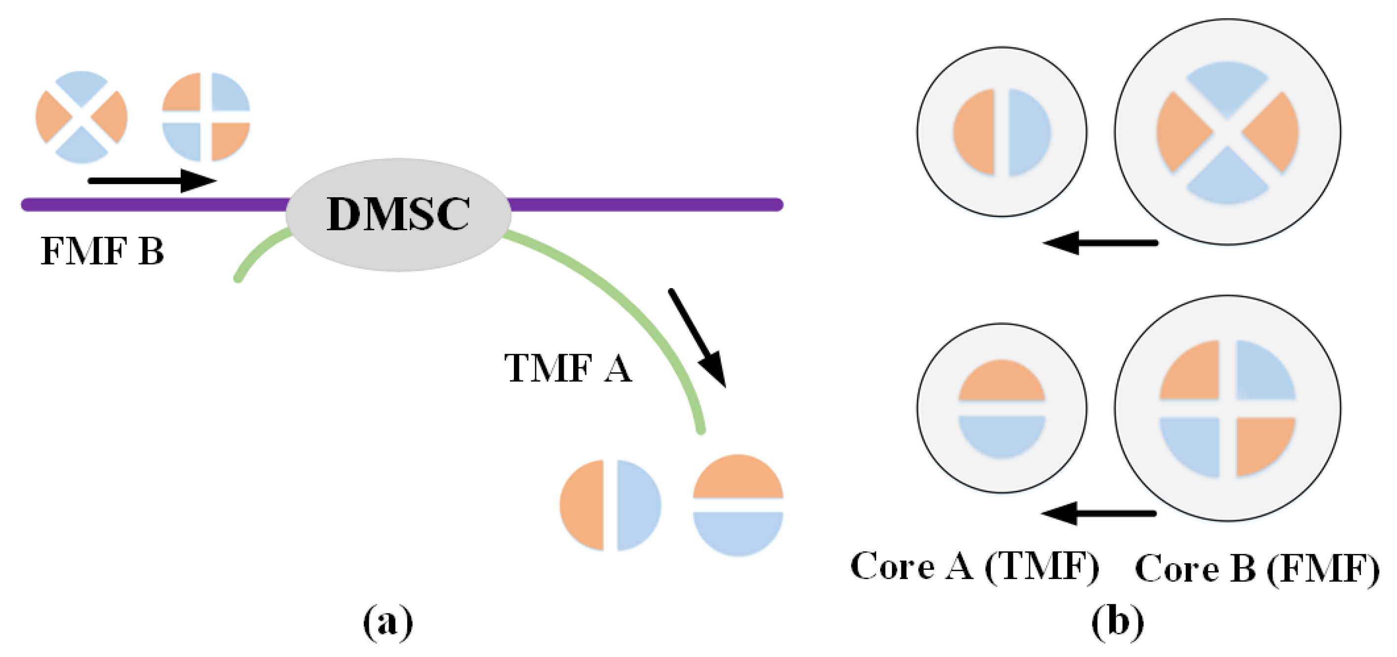
The scheme based on all MSCs requires a two-step process of converting and combining which will inevitably introduce external IL. In addition, the length of the optical paths of the two branches should be strictly identical during the combining so as to avoid temporal delay. In order to solve these problems, a degenerate-mode-selective fiber coupler is proposed for the reception of the degenerate modes. From the perspective of dimensions, if the optical powers in both degenerate modes are converted by the DMSC into a single output fiber, the fiber should sustain at least two spatial degrees of freedom. Consequently, the output fiber has to be an FMF. A straightforward approach is to make the output fiber the same as the original FMF. Then, the DMSC will be a symmetric two-core few-mode fiber coupler. However, this is not the best solution. On one hand, the modal selectivity of the DMSC will vanish by using two identical fibers. This is because the phase-matching conditions are always satisfied between two identical FMFs and the DMSC will inevitably extract energy from unwanted modes. On the other hand, the output fiber of the DMSC is commonly coupled to a PD for optoelectronic conversion. Fibers with smaller core diameters are easier to couple to high-speed PDs with smaller effective areas. Because all degenerate modes only have the same two-fold degeneracy, utilizing a TMF as the output fiber will provide enough dimensionalities and be very useful. Consequently, the DMSC is an asymmetric few-mode fiber coupler which consists of an input FMF and an output TMF, as shown in Figure 4a. In addition, since the LPlma and LPlmb modes can only couple to the same kind of degenerate modes, the proposed LPlm DMSC functions as two independent few-mode couplers. As can be seen in Figure 4b, the LPlma mode of the core B couples to the LP11a mode of core A, and the LPlmb mode of the core B couples to the LP11b mode of the core A.
The necessary conditions of the DMSC are investigated. Assuming that the FMF initially carries unit optical power in LPlma mode and no power was exited in the TMF, the power transfers for the FMF and TMF are as follows:
where Plma(z) is the normalized optical power carried by LPlma mode in the FMF (as functions of the axial distance z along the coupler); P11a(z) is the normalized optical power carried by LP11a mode in the TMF. Fa is the normalized peak power and Ca is the power coupling coefficient. The power transfers for the LPlmb and LP11b modes are similarly. Provided the LPlm mode of the FMF is phase-matched to the LP11 mode of TMF, the power in the LPlma and LPlmb modes of FMF B can completely couple to the LP11a and LP11b modes of TMF A, respectively, when
are simultaneously satisfied (where κa is the coupling coefficient between the LPlma mode of the FMF B and the LP11a mode of the TMF A). κb is the coupling coefficient between the LPlmb mode of the FMF B and the LP11b mode of the TMF A. L is the coupling length, Equations (1) and (2) can be satisfied by tuning the core-to-core distance d and the coupling length L.
Plma(z) = 1 − Fasin2(Caz)
κaL = (2p + 1)π/2
κbL = (2q + 1)π/2
In this paper, the LP11, LP21 and LP31 DMSCs are firstly designed using the beam propagation method. We adopt an FMF with a min|Δneff| up to 1.49 × 10⁻³ among all LP modes [26]. The radii of the core and cladding of the FMF are 8.25 and 62.5 μm, respectively. The Δn of the FMF is 0.748%. The radii of the core and cladding of the TMF are 5 and 62.5 μm, respectively. The Δn of the TMF is 0.688%. In order to achieve the functions of DMSC, the phase-matching condition should be satisfied by tapering the FMF or the TMF. For the LP11 and LP21 DMSCs, the radii of the FMF should be tapered to 34.3 and 50.2 μm, respectively. For the LP31 DMSC, the radius of the TMF needs to be tapered to 58.5 μm. The index profiles of the two fibers of the LP11, LP21, and LP31 DMSCs after tapering are illustrated in Figure 5a–c, respectively. The coupling length L and the core-to-core distances d are designed by parameter sweeping. The coupling efficiencies versus L for both degenerate modes are calculated for each value of d. After the optimization, the core-to-core distances d are set to 12.53, 14.42 and 16.63 μm for the LP11, LP21, and LP31 DMSCs, respectively. The coupling lengths L are set to 6.17, 5.18 and 21.33 mm for the LP11, LP21, and LP31 DMSCs, respectively. In this case, the coupling efficiencies of both degenerate modes will reach the maximum simultaneously, as depicted in Figure 5d–f.
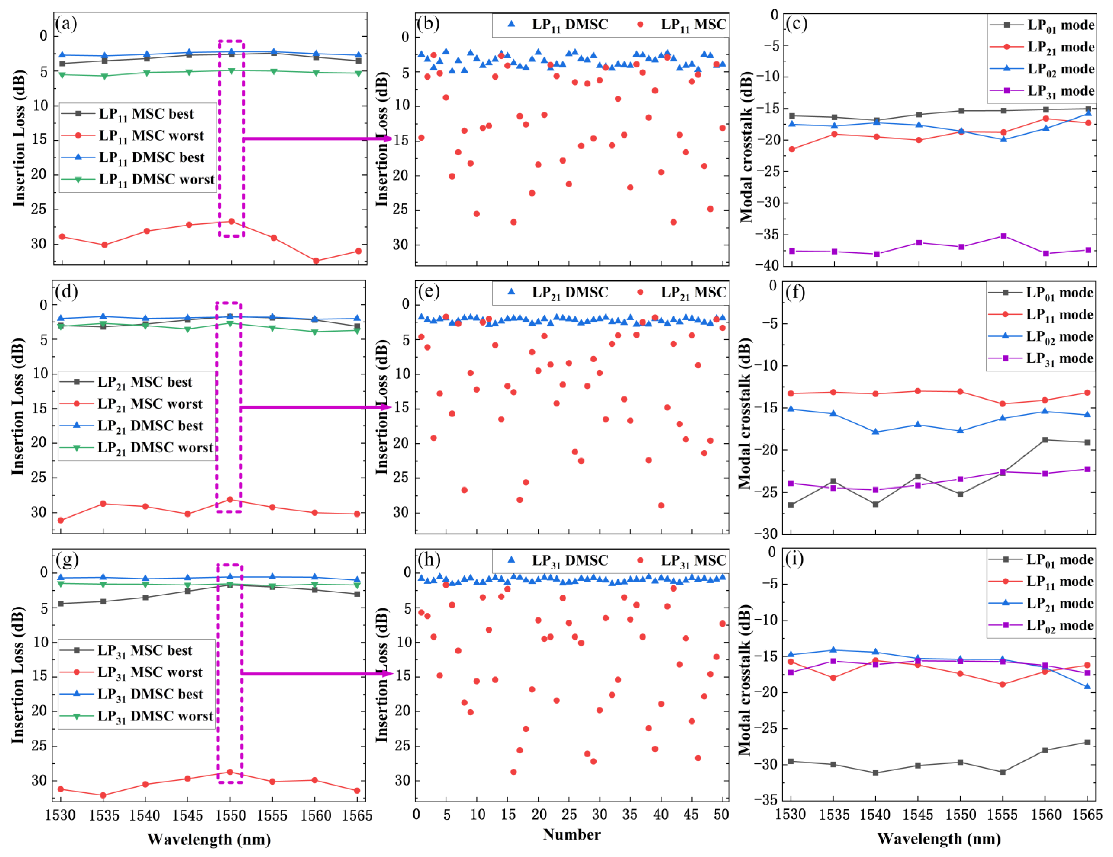
Similar to the regular all-fiber MSCs, the designed LP11, LP21 and LP31 DMSCs are also fabricated utilizing the taper and polish method. We measured the power stability and IL of the three DMSCs using the setup shown in Figure 6. The optical power in the target LP mode is generated by a regular MSC. A mode rotator is employed to adjust the orientations of the modal field before the DMSC. The demultiplexing performances of the LP11, LP21 and LP31 MSCs are also characterized as a contrast. The wavelength of the light source over the C band is tuned and the output optical power of the TMF of the DMSC (the SMF of the MSC) is recorded. As can be seen, the best and worst insertion loss for the LP11, LP21 and LP31 DMSCs(MSCs) after a 50 random adjustments of the modal field over the C band are shown in Figure 7a,d,g. The results of the insertion loss measurements at 1550 nm are illustrated in Figure 7b,e,h, respectively. It can be seen that the variation in the IL of the LP11, LP21 and LP31 MSCs is quite severe, and only minor variation happens in the proposed DMSCs. The fluctuations of the optical power are all lager than 20 dB for three regular MSCs over the C band. Meanwhile, the average variations are 2.7, 1.9 and 3.3 dB for the LP11, LP21 and LP31 DMSCs, respectively.
The modal crosstalk performance of the DMSCs is characterized by inputting the optical power of the other three modes, respectively. The experimental results for the LP11, LP21, and LP31 DMSCs are shown in Figure 7c,f,i. Over the C-band, the largest modal crosstalk for the LP11 DMSC is −15.7 dB, while it is −13.4 and −15.4 dB for the LP21 and LP31 DMSCs, respectively. The modal crosstalk comes from phase mismatch during the fabrication. Moreover, other LP modes may slightly couple to the LP01 mode of the output TMF. The modal selectivity performance can be optimized during the manufacturing process by more precisely phase-matching the conditions.
4. Discussions and Conclusions
In this paper, we propose two kinds of degenerate-mode-reception scheme. The first one is based on regular all-fiber MSCs which consist of converting and combing steps. Three fiber couplers are required for each non-circular-symmetric LP mode in the first scheme, which also requires precise time alignment to avoid signal broadening. The second method is based on a novel DMSC, which could achieve the demultiplexing of both degenerate modes independently. Therefore, the DMSC is superior in size and costs as a two-core fiber coupler. However, according to the experimental results, the demultiplexing efficiency of the first scheme is stabler than that of the second one. Modal crosstalk from the coupling to the LP01 mode of the TMF should also be noted in the second scheme. Actually, the schemes presented in this paper can not only be fabricated using an all-fiber solution; we also expect to utilize other waveguide structures, such as femtosecond directly written integrated couplers and three-dimensional polymer waveguides [27,28]. Since directly written and polymer couplers are weakly guiding waveguides, the size of the core and the coupling behaviors are similar to those of few-mode fiber couplers. In addition, it is easier to achieve a directly written waveguide with a three-dimensional coupler than with fiber-based devices.
Author Contributions
Conceptualization, Y.G. and J.L.; methodology, J.C. and Y.G.; software, J.C.; validation, Y.G. and J.C.; writing—original draft preparation, Y.G. and J.C.; writing—review and editing, J.L. and Y.G.; supervision, X.Z. and Z.C.; project administration, J.L.; funding acquisition, Y.G. and J.L. All authors have read and agreed to the published version of the manuscript.
Funding
This research was funded by the National Natural Science Foundation of China, grant number 62101009, U20A20160, and Pengcheng Zili Project, grant number PCL2023AS2-4.
Institutional Review Board Statement
Not applicable.
Informed Consent Statement
Not applicable.
Data Availability Statement
The original contributions presented in the study are included in the article; further inquiries can be directed to the corresponding author.
Conflicts of Interest
Author Jian Cui was employed by the China Mobile Communications Group Co., Ltd. The remaining authors declare that the research was conducted in the absence of any commercial or financial relationships that could be construed as a potential conflict of interest.
References
- Ghiasi, A. Large data centers interconnect bottlenecks. Opt. Express 2015, 23, 2085–2090. [Google Scholar] [CrossRef]
- Richardson, D.J.; Fini, J.M.; Nelson, L.E. Space-division multiplexing in optical fibres. Nat. Photonics 2013, 7, 354–362. [Google Scholar] [CrossRef]
- Li, G.; Bai, N.; Zhao, N.; Xia, C. Space-division multiplexing: The next frontier in optical communication. Adv. Opt. Photonics 2014, 6, 413–487. [Google Scholar] [CrossRef]
- Ryf, R.; Randel, S.; Gnauck, A.H.; Bolle, C.A.; Sierra, A.; Mumtaz, S.; Esmaeelpour, M.; Burrows, E.C.; Essiambre, R.-J.; Winzer, P.J.; et al. Mode-division multiplexing over 96 km of few-mode fiber using coherent 6 × 6 MIMO processing. J. Light. Technol. 2012, 30, 521–531. [Google Scholar] [CrossRef]
- Ryf, R.; Fontaine, N.K.; Wittek, S.; Choutagunta, K.; Mazur, M.; Chen, H.; Alvarado-Zacarias, J.C.; Amezcua-Correa, R.; Capuzzo, M.; Kopf, R.; et al. High-Spectral-Efficiency Mode-Multiplexed Transmission over Graded-Index Multimode Fiber. In Proceedings of the 2018 European Conference on Optical Communication (ECOC), Rome, Italy, 23–27 September 2018. [Google Scholar]
- Igarashi, K.; Park, K.J.; Tsuritani, T.; Morita, I.; Kim, B.Y. All-fiber-based selective mode multiplexer and demultiplexer for weakly-coupled mode-division multiplexed systems. Opt. Commun. 2018, 408, 58–62. [Google Scholar] [CrossRef]
- Shen, S.; Yang, Z.; Li, X.; Zhang, S. Periodic propagation of complex-valued hyperbolic-cosine-Gaussian solitons and breathers with complicated light field structure in strongly nonlocal nonlinear media. Commun. Nonlinear Sci. Numer. Simulat. 2021, 103, 106005–106017. [Google Scholar] [CrossRef]
- Kogelnik, H.; Winzer, P.J. Modal birefringence in weakly guiding fibers. J. Light. Technol. 2012, 30, 2240–2245. [Google Scholar] [CrossRef]
- May, A.R.; Zervas, M.Z. Few-mode fibers with improved mode spacing. In Proceedings of the 2015 European Conference on Optical Communication (ECOC), Valencia, Spain, 27 September–1 October 2015. [Google Scholar]
- Jiang, S.; Ma, L.; Zhang, Z.; Xu, X.; Wang, S.; Du, J.; Yang, C.; Tong, W.; He, Z. Design and Characterization of Ring-Assisted Few-Mode Fibers for Weakly Coupled Mode-Division Multiplexing Transmission. J. Light. Technol. 2018, 36, 5547–5555. [Google Scholar] [CrossRef]
- Love, J.D.; Riesen, N. Mode-selective couplers for few-mode optical fiber networks. Opt. Lett. 2012, 37, 3990–3992. [Google Scholar] [CrossRef]
- Soma, D.; Beppu, S.; Wakayama, Y.; Igarashi, K.; Tsuritani, T.; Morita, I.; Suzuki, M. 257-Tbit/s Weakly Coupled 10-Mode C + L-Band WDM Transmission. J. Light. Technol. 2018, 36, 1375–1381. [Google Scholar] [CrossRef]
- Igarashi, K.; Kawabata, G. Statistics of mode couplings induced by concatenated multiple connections in weakly-coupled few-mode fibers. Opt. Commun. 2020, 467, 125685–125690. [Google Scholar] [CrossRef]
- Ip, E.; Milione, G.; Li, M.; Cvijetic, N.; Kanonakis, K.; Stone, J.; Peng, G.; Prieto, X.; Montero, C.; Moreno, V.; et al. SDM transmission of real-time 10GbE traffic using commercial SFP + transceivers over 0.5km elliptical-core few-mode fiber. Opt. Express 2015, 23, 17120–17126. [Google Scholar] [CrossRef]
- Li, J.; Du, J.; Ma, L.; Li, M.; Jiang, S.; Xu, X.; He, Z. Coupling analysis of non-circular-symmetric modes and design of orientation-insensitive few-mode fiber couplers. Opt. Commun. 2017, 383, 42–49. [Google Scholar] [CrossRef]
- Riesen, N.; Love, J.D. Ultra-Broadband Tapered Mode-Selective Couplers for Few-Mode Optical Fiber Networks. IEEE Photon. Technol. Lett. 2013, 25, 2501–2504. [Google Scholar] [CrossRef]
- Liu, H.; Wen, H.; Alvarado-Zacarias, J.C.; Antonio-Lopez, J.E.; Wang, N.; Sillard, P.; Amezcua-Correa, R.; Li, G. Demonstration of stable 3 × 10 Gb/s mode group-multiplexed transmission over a 20 km few-mode fiber. In Proceedings of the 2017 Optical Fiber Communications Conference and Exhibition (OFC), San Diego, CA, USA, 26–28 March 2018. [Google Scholar]
- Lenglé, K.; Insou, X.; Jian, P.; Barré, N.; Denolle, B.; Bramerie, L.; Labroille, G. 4 × 10 Gbit/s bidirectional transmission over 2 km of conventional graded-index OM1 multimode fiber using mode group division multiplexing. Opt. Express 2016, 24, 28594–28605. [Google Scholar] [CrossRef]
- Benyahya, K.; Simonneau, C.; Ghazisaeidi, A.; Barré, N.; Jian, P.; Morizur, J.-F.; Labroille, G.; Bigot, M.; Sillard, P.; Provost, J.G.; et al. Multiterabit Transmission over OM2 Multimode Fiber with Wavelength and Mode Group Multiplexing and Direct Detection. J. Light. Technol. 2018, 36, 355–360. [Google Scholar] [CrossRef]
- Benyahya, K.; Simonneau, C.; Ghazisaeidi, A.; Muller, R.; Bigot, M.; Sillard, P.; Jian, P.; Labroille, G.; Renaudier, J.; Charlet, G. 200 Gb/s Transmission over 20 km of FMF Fiber using Mode Group Multiplexing and Direct Detection. In Proceedings of the 2018 European Conference on Optical Communication (ECOC), Rome, Italy, 23–27 September 2018. [Google Scholar]
- Shimizu, S.; Okamoto, A.; Mizukawa, F.; Ogawa, K.; Tomita, A.; Takahata, T.; Shinada, S.; Wada, N. Fundamental Demonstration of Mode-Group Demultiplexing Technique Based on Volume Holographic Demultiplexer. In Proceedings of the 2017 22nd Microoptics Conference (MOC), Tokyo, Japan, 19–22 November 2017. [Google Scholar]
- Shinada, S.; Shimizu, S.; Shiba, T.; Takahata, T.; Okamoto, A.; Wada, N. Spatial-Mode Demultiplexer using 1550-nm-band Angularly Multiplexed Volume Holograms. In Proceedings of the 2018 European Conference on Optical Communication (ECOC), Rome, Italy, 23–27 September 2018. [Google Scholar]
- Cui, J.; Gao, Y.; Huang, S.; Yu, J.; Shen, L.; Zhang, L.; Yan, C.; Yang, L.; Wang, R.; He, Y.; et al. Low-modal-crosstalk Orthogonal Combine Reception for Degenerate Modes in IM/DD MDM Transmission. Opt. Express 2023, 31, 8586–8594. [Google Scholar] [CrossRef]
- Cui, J.; Gao, Y.; Huang, S.; Yu, J.; Liu, J.; Jia, J.; He, Y.; Chen, Z.; Li, J. Five-LP-mode IM/DD MDM Transmission Based on Degenerate-mode-selective Couplers with Side-polishing Processing. J. Light. Technol. 2023, 41, 2991–2998. [Google Scholar] [CrossRef]
- Park, K.J.; Song, K.Y.; Kim, Y.K.; Lee, J.H.; Kim, B.Y. Broadband mode division multiplexer using all fiber mode selective couplers. Opt. Express 2016, 24, 3543–3549. [Google Scholar] [CrossRef]
- Ge, D.; Gao, Y.; Yang, Y.; Shen, L.; Li, Z.; Chen, Z.; He, Y.; Li, J. A 6-LP-mode ultralow-modal-crosstalk double-ring-core FMF for weakly-coupled MDM transmission. Opt. Commun. 2019, 451, 97–103. [Google Scholar] [CrossRef]
- Gross, S.; Riesen, N.; Love, J.D.; Withford, M.J. Three-dimensional ultra-broadband integrated tapered mode multiplexers. Laser Photonics Rev. 2014, 8, 81–85. [Google Scholar] [CrossRef]
- Dong, J.; Chiang, K.S.; Jin, W. Compact three-dimensional polymer waveguide mode multiplexer. J. Light. Technol. 2015, 33, 4580–4588. [Google Scholar] [CrossRef]
Figure 1.
The proposed all-fiber mode demultiplexers for LP-mode MDM transmission.
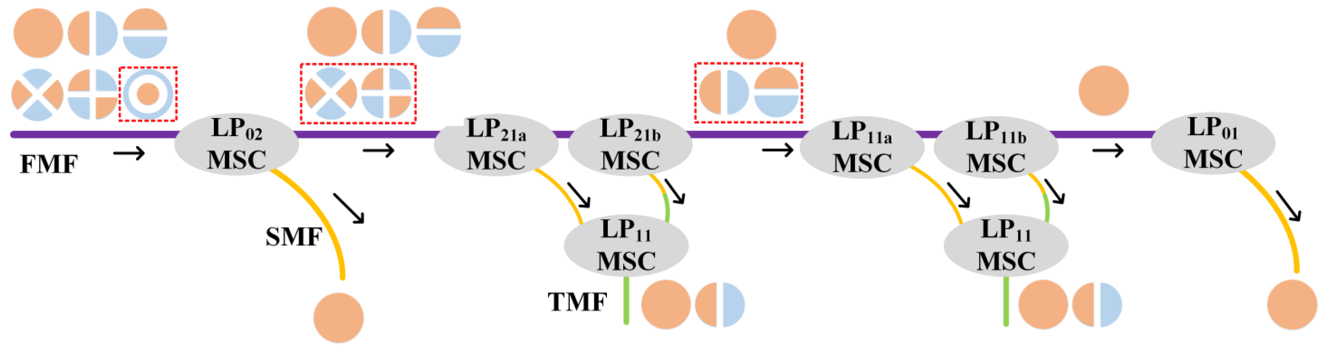
Figure 2.
Refractive index profile of the (a) FMF, (b) customized SMF and (c) TMF. (d) The neff of the 4 LP modes in FMF and the LP01 mode in two kinds of SMFs versus tapered radius. (e) The neff of the LP11 mode in TMF and the LP01 mode in standard SMF versus tapered radius.
Figure 2.
Refractive index profile of the (a) FMF, (b) customized SMF and (c) TMF. (d) The neff of the 4 LP modes in FMF and the LP01 mode in two kinds of SMFs versus tapered radius. (e) The neff of the LP11 mode in TMF and the LP01 mode in standard SMF versus tapered radius.
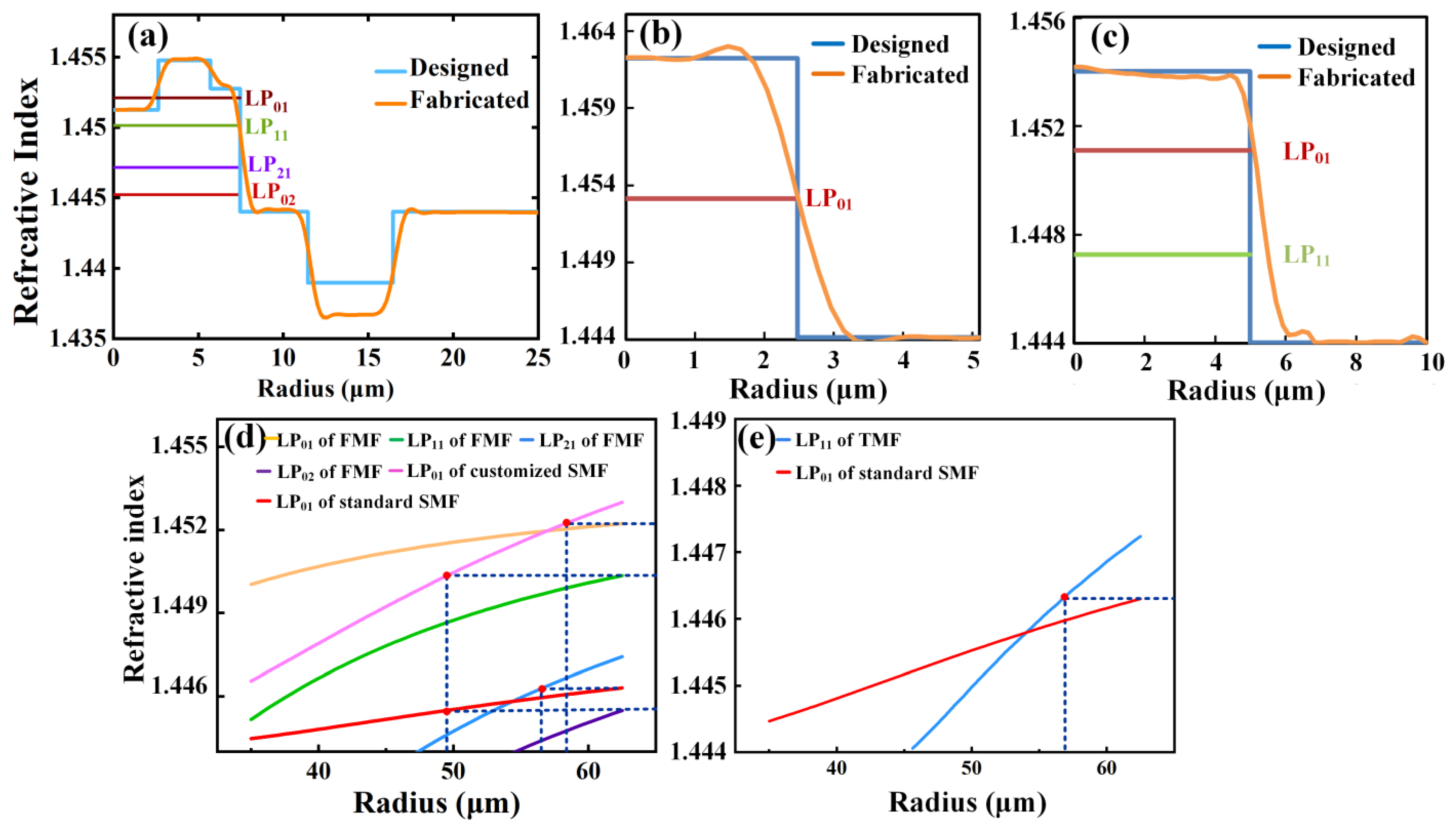
Figure 3.
(a) Setup for characterization of the fabricated LP11 and LP21 demultiplexers. IL measurements with 50-times randomly adjusted spatial orientations at 1550 nm for (b) LP11 mode and (c) LP21 mode. Modal crosstalk over the C-band for (d) LP11 and (e) LP21 demultiplexers.
Figure 3.
(a) Setup for characterization of the fabricated LP11 and LP21 demultiplexers. IL measurements with 50-times randomly adjusted spatial orientations at 1550 nm for (b) LP11 mode and (c) LP21 mode. Modal crosstalk over the C-band for (d) LP11 and (e) LP21 demultiplexers.
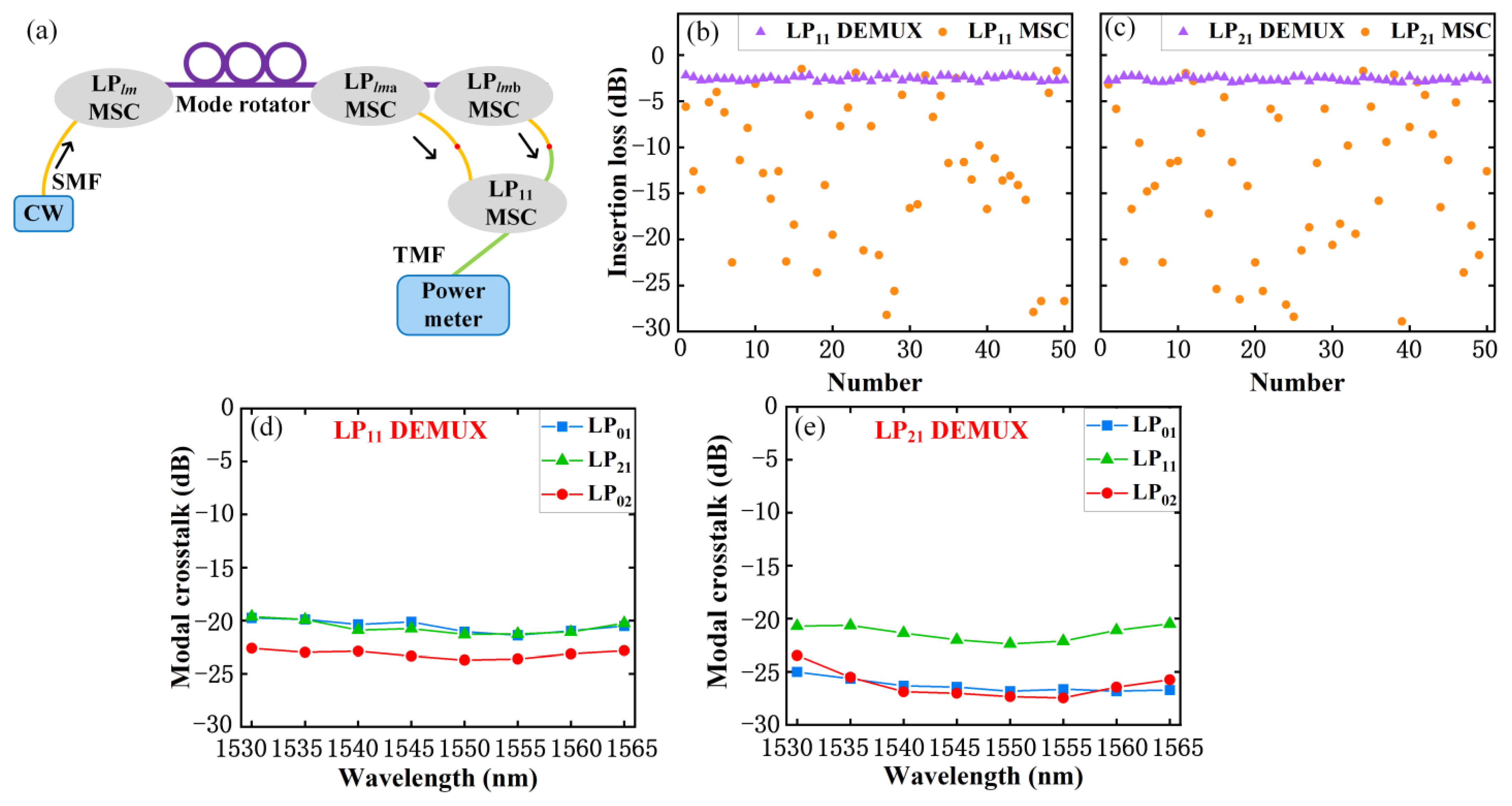
Figure 4.
(a) Structure of the DMSC, where FMF B is the input fiber and TMF A is the output fiber. (b) Coupling behaviors of the LP modes in the DMSC.
Figure 4.
(a) Structure of the DMSC, where FMF B is the input fiber and TMF A is the output fiber. (b) Coupling behaviors of the LP modes in the DMSC.

Figure 5.
Index profile of the (a) LP11, (b) LP21, and (c) LP31 DMSC. Coupling curves of the (d) LP11, (e) LP21, and (f) LP31 DMSC.
Figure 5.
Index profile of the (a) LP11, (b) LP21, and (c) LP31 DMSC. Coupling curves of the (d) LP11, (e) LP21, and (f) LP31 DMSC.
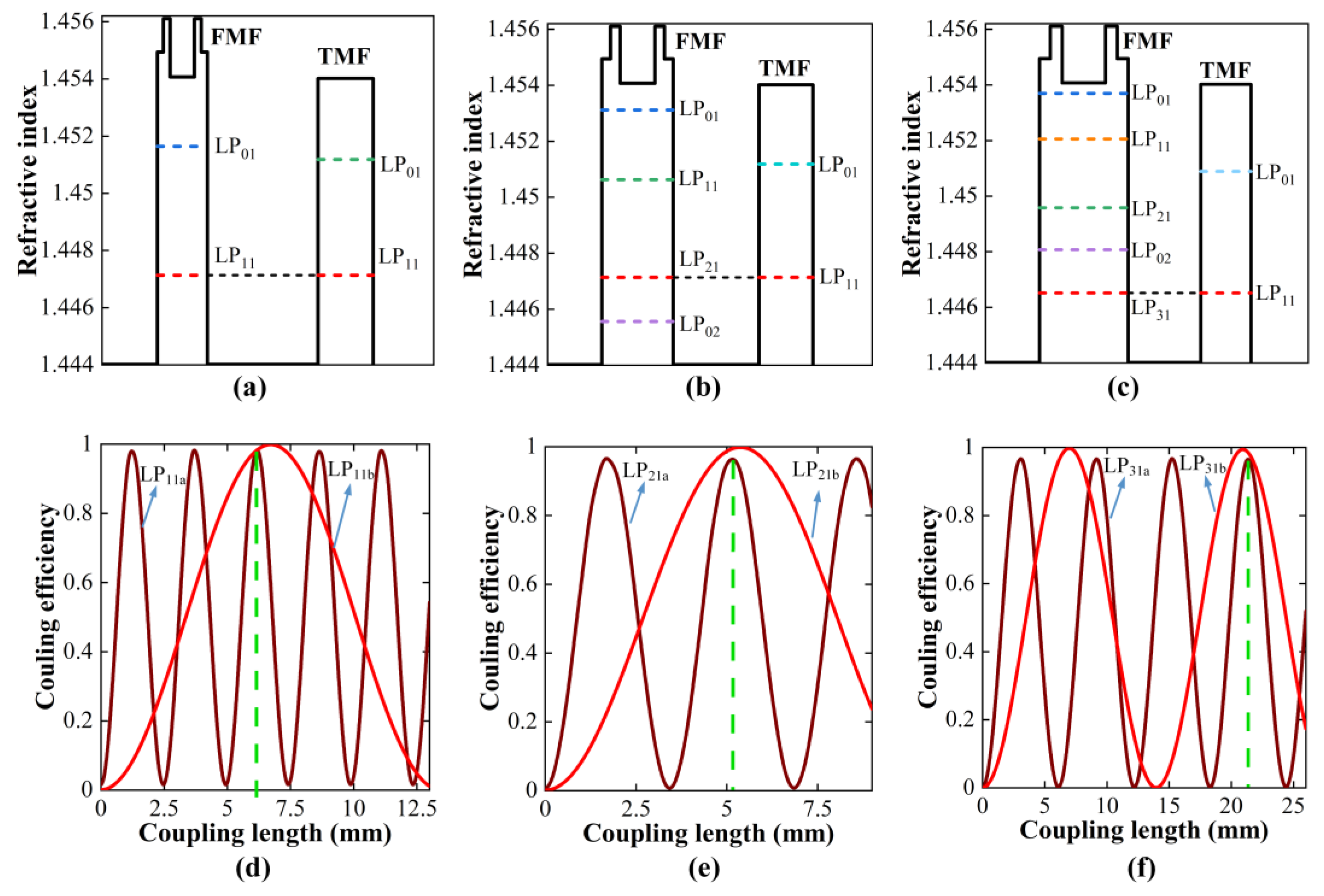
Figure 6.
Setup for characterization of the fabricated LP11, LP21 and LP31 DMSCs.
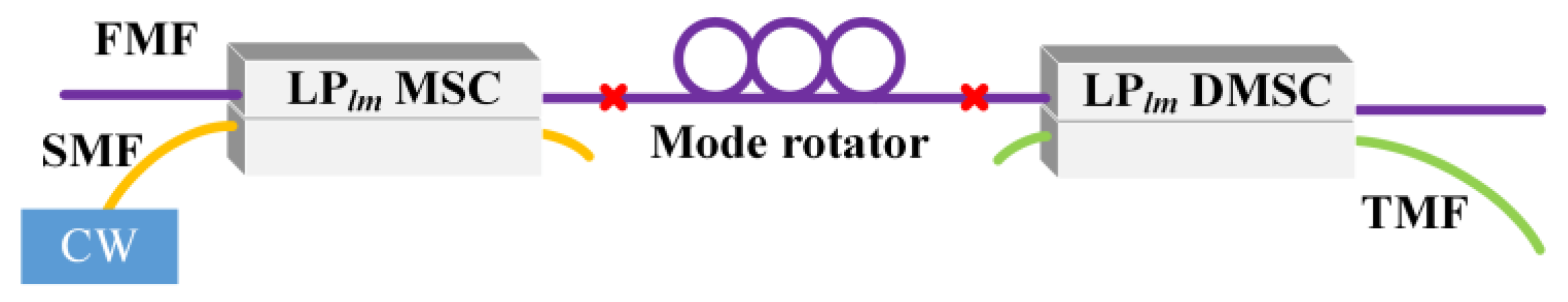
Figure 7.
Best and worst IL over the C-band for (a) LP11 DMSC/MSC, (d) LP21 DMSC/MSC, and (g) LP31 DMSC/MSC. Fifty IL measurements with random input spatial orientations at 1550 nm for (b) LP11 DMSC/MSC, (e) LP21 DMSC/MSC, and (h) LP31 DMSC/MSC. Modal crosstalk over the C-band for (c) LP11 DMSC, (f) LP21 DMSC, and (i) LP31 DMSC.
Disclaimer/Publisher’s Note: The statements, opinions and data contained in all publications are solely those of the individual author(s) and contributor(s) and not of MDPI and/or the editor(s). MDPI and/or the editor(s) disclaim responsibility for any injury to people or property resulting from any ideas, methods, instructions or products referred to in the content. |
© 2024 by the authors. Licensee MDPI, Basel, Switzerland. This article is an open access article distributed under the terms and conditions of the Creative Commons Attribution (CC BY) license (https://creativecommons.org/licenses/by/4.0/).
Share and Cite
MDPI and ACS Style
Gao, Y.; Cui, J.; Zhou, X.; Chen, Z.; Li, J. All-Fiber Low-Modal-Crosstalk Demultiplexers for DSP-Free IM/DD LP-Mode MDM Transmission. Photonics 2024, 11, 271. https://doi.org/10.3390/photonics11030271
AMA Style
Gao Y, Cui J, Zhou X, Chen Z, Li J. All-Fiber Low-Modal-Crosstalk Demultiplexers for DSP-Free IM/DD LP-Mode MDM Transmission. Photonics. 2024; 11(3):271. https://doi.org/10.3390/photonics11030271
Chicago/Turabian StyleGao, Yuyang, Jian Cui, Xian Zhou, Zhangyuan Chen, and Juhao Li. 2024. "All-Fiber Low-Modal-Crosstalk Demultiplexers for DSP-Free IM/DD LP-Mode MDM Transmission" Photonics 11, no. 3: 271. https://doi.org/10.3390/photonics11030271
Note that from the first issue of 2016, this journal uses article numbers instead of page numbers. See further details here.