1. Introduction
One of the most prominent characteristics of silica fibers is the exceptionally weak absorption in the infrared wavelength range. This quality makes fibers not only the key element in high-speed optical communication systems, but also an outstanding platform for nonlinear optics [
1]. Second-order nonlinear effects have been observed in fibers since early 1980s [
2,
3]. To create an effective second order polarization, apart from strictly zero in bulk silica glass, periodic poling of fibers is commonly used [
4,
5]. In combination with the Quasi-Phase Matching (QPM) [
6], this allows us to achieve high efficiency of second harmonic generation (SHG) [
7] and parametric down-conversion [
8,
9] in fibers. The latter process is a convenient tool for generation of correlated photon pairs [
8,
9,
10]. It is desirable to advance efficient fiber-based photon pair sources, as they can be seamlessly connected with telecommunication systems. However, to achieve the required efficiency of second-order nonlinear processes in periodically poled fibers, one needs to use large propagation distances, typically of the order of a few dozens of centimeters [
7]. This poses serious limitations to miniaturization of such nonlinear functionalities, and undermines their potential on-chip integration.
In contrast, χ
2-crystals such as lithium niobate (LiNbO
3, LN) offer inherently strong second-order nonlinear response. As a result, efficient nonlinear effects are observed in χ
2-crystal waveguides over propagation distances as short as few millimeters [
11,
12,
13,
14]. Recent developments in production and nano-structuring of LN thin film (LiNbO
3 on Insulator, LNOI) [
15,
16] have led to the advancement of compact high-contrast photonic devices [
17,
18,
19,
20,
21,
22]. The waveguide is the fundamental structure in these devices. However, propagation losses of the LNOI waveguides are at an appreciable level of few dB/cm, and when the waveguide cross-sectional dimensions are reduced below 1 μm, the losses rise even further to the levels of ~10 dB/cm [
17]. Periodic poling of such waveguides, required for QPM, also proves to be a challenging task [
15]. Furthermore, while the period of the poling is fixed for a particular pump wavelength, this leaves no room for adjustments of individual waveguides integrated in a circuit. The conventional method of temperature control is not suitable for high-density on-chip integration because of the lack of sufficient resolution. Obviously, additional degrees of freedom for phase-matching adjustment are demanded from the viewpoint of on-chip integration.
Recently, researchers have considered the possibility to achieve second-order nonlinear response in microfibers (MFs) without periodic poling, by enhancing surface nonlinearities [
23,
24] or coating MF with organic molecules possessing strong second-order nonlinear response [
25]. Direct phase matching was also considered for the so-called M-waveguides, which have specially engineered layered core structure [
26]. The major bottleneck of such structures is in the necessity to achieve phase matching between different modes, which is only possible in a narrow interval of the pump wavelengths or fiber radius. Also, the possibility of clean chemical coating of MFs with diameters of the order of 1 μm and below, required for phase matching, has not been demonstrated yet. However, these studies have led to an important inspiration that the QPM second-order nonlinearity, which is commonly used in weakly-guiding structures, could possibly be replaced by an inter-modal phase matching second-order nonlinearity in high-contract waveguides. Besides, the match of the transmission windows of silica and LN (from visible to mid-infrared), and their relatively close refractive indices (at 1550 nm,
n = 1.44 for silica and
no = 2.21,
ne = 2.14 for LN, in contrast to
n =1 for air and
n = 3.46 for silicon) encourage us to explore hybrid structures composed of a microfiber and LN thin film.
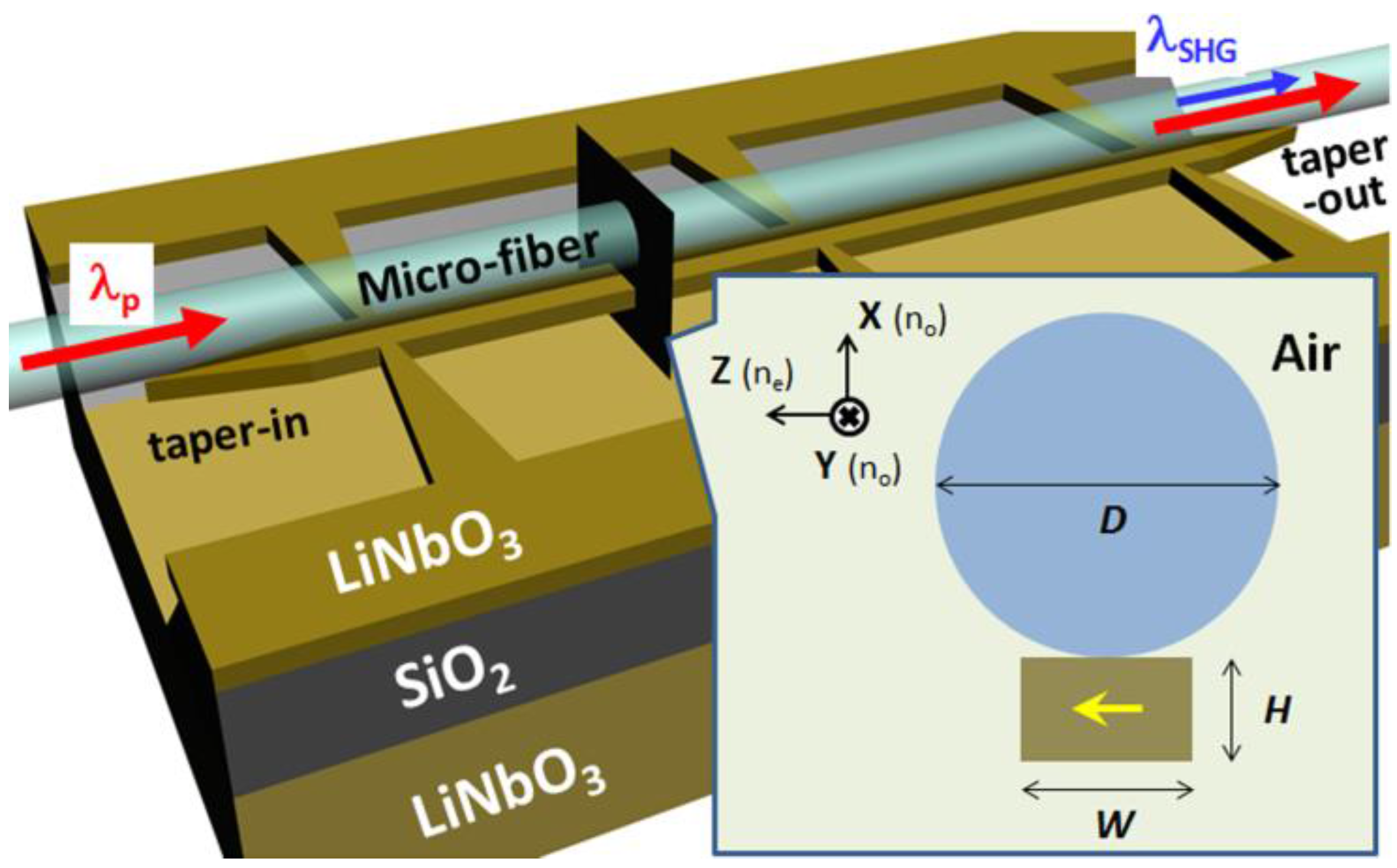
In this work we introduce a MF-LNOI hybrid waveguide which features the combination of a strong second-order nonlinearity, and tunability in a wide range of wavelengths and geometrical sizes. The structure represents a free-standing X-cut LNOI waveguide [
27] with the dimension of
H ×
W ×
L attached to a side of a microfiber with the diameter
D, see
Figure 1. Van der Waals attraction keeps together the two parts at their relatively symmetric position [
28]. When necessary, the whole structure can also be detached and reassembled at other positions along the microfiber. Note that there is no chemical treatment in the whole fabrication process, ensuring a contamination-free waveguide. By inclusion of in- and out-tapering sections in the LNOI waveguide, one can efficiently couple the pump power into and get the SHG light out of the hybrid waveguide, avoiding insertion losses with fiber optical systems and laser damages associated with input facets of waveguides.
Figure 1.
Schematic view of the microfiber-lithium niobate on insulator (MF-LNOI) hybrid waveguide. The optic axis of LN crystal is indicated by the yellow arrow.
Figure 1.
Schematic view of the microfiber-lithium niobate on insulator (MF-LNOI) hybrid waveguide. The optic axis of LN crystal is indicated by the yellow arrow.
2. Calculations
When the fiber diameter and the waveguide transverse dimensions are comparable to the operating wavelengths, hybridization of the fiber and the waveguide modes occurs. In this regime, a significant fraction of power in each mode enters into the LN part of the structure, thus creating a scope for potentially strong second-order nonlinear interactions, see left panels in
Figure 2. Increasing the fiber diameter, the modes gradually transform into conventional fiber modes, see right panels in
Figure 2.
To describe SHG process in the hybrid waveguide, we expand the total electric field as the sum of the fundamental and second harmonics,
. Here
,
and
are the modal profiles,
βp and
βs are the corresponding propagation constants, normalization factors
Nj (
j =
p,
s) are chosen such that |
Ap|
2 and |
As|
2 give powers carried by the fundamental and second harmonic modes in
y-direction, respectively,
. Assuming the amplitude of the second harmonic to be much weaker than the pump, using perturbation expansion of Maxwell equations, for the slowly varying amplitude
As(
y) the following equation is obtained [
23,
24,
29]:
where
and the nonlinear coefficient is:
is the reduced second-order nonlinear tensor [
30], the integration is done over the LNOI waveguide area. We estimate the attenuation of the hybrid structure to be of the order of few dB/cm, mainly caused by scatterings and absorptions of LNOI waveguide [
17]. For propagation distances below 1 mm, considered in this work, we therefore can neglect attenuation in Equation (1).
We choose the optical axis of LNOI thin film to be oriented horizontally, see
Figure 1. Hence modes with appreciable
Ez-components inside the LN crystal experience strong nonlinearity. In
Figure 2 we demonstrate the possibility of phase matching between the fundamental HE
11-like mode (HE11 mode in MF + TE
00 mode in LNOI) at the pump wavelength
λp = 1.5 μm and the higher order TE01-like mode (TE
01 mode in MF + TE
01 mode in LNOI) at the second harmonic wavelength
λs =
λp/2 = 0.75 μm. Both hybrid modes in
Figure 2 have dominant electric field components oriented along
z-axis inside LN. In this case, the integrant in Equation (2) can be approximated as
with
d33 ≈ 19 pm/V at 1.5 μm [
31].
Figure 2.
HE11-like mode at λp = 1.5 μm and TE01-like mode at λs = 0.75 μm: light intensity and the electric field polarization. Modal profiles are plotted for D = 3 μm (right panels) and D ≈ 1 μm (corresponding to phase matching, left panels). The effective indices as functions of the fiber diameter are shown in the central panel. The waveguide dimensions are: H = 300 nm, W = 495 nm. The effective indices of pure MF modes and pure LNOI waveguide modes are plotted with dashed lines and dotted lines, respectively.
In a pure MF (without LNOI), the material dispersion of silica glass (the refractive indices of silica at the two wavelengths are 1.4446 and 1.4542, respectively) can be compensated by the modal dispersion only near the cutoff of both modes:
D ≈ 0.58 μm,
neff ≈ 1.02, see dashed curves in the central panel of
Figure 2. In the MF-LNOI structure, the hybridization of pure MF and pure LNOI modes via the avoided crossings shifts the phase matching to a larger MF diameter,
D ≈ 1 μm, and a considerably higher effective index,
neff ≈ 1.31, see solid curves in the central panel of
Figure 2. While the diameter increase is important from the viewpoint of MF fabrication, the larger effective index implies a much stronger field confinement and hence more effective nonlinear interaction.
Large refractive index contrasts between silica and air, LN and air, allow guidance of light in a compact sub-micrometer scale structure, but also result in a high sensitivity of guided modes to size variations. Keeping the waveguide height
H fixed, as dictated by the LNOI wafer characteristics with the variation less than 1 nm [
15], there are two other geometrical parameters left to adjust propagation constants of the modes: the fiber diameter
D and the waveguide width
W. In
Figure 3 the detuning Δ
β between propagation constants of the HE
11-like and TE
01-like modes is plotted as functions of
W,
D and
λp. The calculations were done with the help of Comsol Multiphysics, using the material dispersions of silica [
1] and LN [
30] avaliable in the literature. For a fixed pump wavelength
λp, the phase matching is obtained by adjustments of
W and
D, see
Figure 3a. Likewise, one can achieve phase matching within a wide range of pump wavelength by fixing either
D or
W, see
Figure 3b,c.
Figure 3.
Detuning Δβ between the second harmonic and pump modes as functions of pump wavelength λp, fiber diameter D and waveguide width W: (a) Fixed λp = 1.5 μm. (b) Fixed D = 1 μm. (c) Fixed W = 495 nm. Dashed line indicates the phase matching condition Δβ = 0. Broadband phase-matching is expected in the conditions marked by blue circles.
Figure 4.
Nonlinear coefficient as function of the fiber diameter (
a) Pump wavelength. (
b) For the case of perfectly matched fundamental and second harmonics, cf. dashed curves in
Figure 3a,b, respectively.
Figure 4.
Nonlinear coefficient as function of the fiber diameter (
a) Pump wavelength. (
b) For the case of perfectly matched fundamental and second harmonics, cf. dashed curves in
Figure 3a,b, respectively.
The direct phase matching between different modes, as opposed to QPM, removes the necessity of periodic grating structures, significantly reducing the overall waveguide size, and hence being attractive for high-density on-chip integration. However, the direct phase matching can only be achieved between the fundamental and a higher order mode. This introduces additional implications, since the electric field profiles in different modes strongly affect the resulting nonlinear coefficient in Equation (2). In particular, the overlap integral in Equation (2) between the TE
00 and TE
01 modes of an isolated LNOI waveguide (
i.e., free-standing and without the fiber) is strictly zero due to the different symmetries of the two modes. The introduction of the fiber, and the subsequent hybridization between the fiber and the waveguide modes, change the structure of the modes and lead to non-zero values of
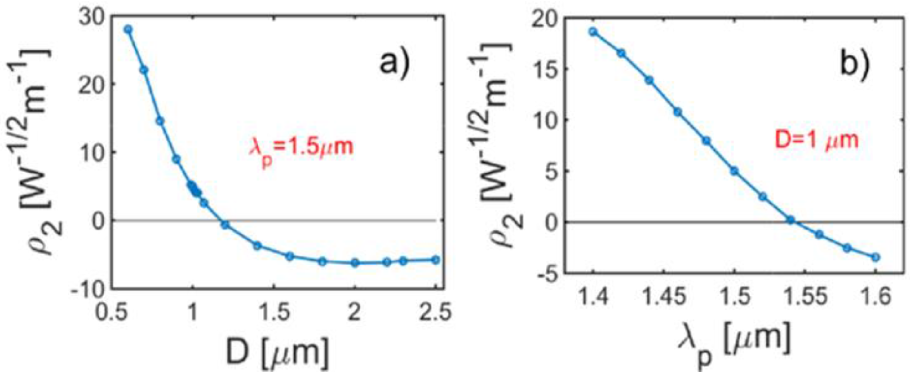
ρ2. It is seen that the magnitude and sign of the resulting nonlinear coefficient are sensitive to variations in sizes and the pump wavelength,
Figure 4. Crucially, the possibility to achieve phase matching in a wide range of three parameters,
W,
D and
λp, allows one to adjust the nonlinearity independently for the required pump wavelength or fixed fiber/waveguide dimensions.
3. Results and Discussion
Of all the three parameters, the waveguide width
W is identified to bring the strongest variations in Δ
β and
ρ2 both crucial for the efficiency of SHG. To investigate possible effects of random variations of the waveguide width in a realistic structure, we performed numerical integration of Equation (1) with variable coefficients Δ
β and
ρ2 along the propagation distance. The structure was split into small sections of lengths
Lm +
δlj, the waveguide width inside each
j-th section (
j = 1,2,3,…) was fixed to
Wm +
δwj. Here
δlj and
δwj are random perturbations. We chose the mean length of each section to be
Lm = 10 μm with the maximal amplitude of variation max(|
δlj|) = 5 μm. The mean waveguide width was taken as
Wm = 442 nm, which gives the phase matching at
λp = 1.5 μm and
D = 0.7 μm, the corresponding value of the nonlinear coefficient is
ρ2 = 22
W−1/2m−1, see
Figure 4a. We let the variation of width to have the maximal amplitude max(|
δwj|) = 5 nm. Such level of sidewall roughness has recently been demonstrated in a dry-etched LNOI device [
21]. A typical profile of the structure is shown with the light-grey curve in
Figure 5. The corresponding variations of Δ
β and
ρ2 were obtained by approximating the functions Δ
β(
W) and
ρ2(
W) with linear dependencies. The linear coefficients
and
were calculated from the numerical data in
Figure 3a and
Figure 4a, respectively.
The resulting SHG conversion efficiency
η = |
As|
2/|
Ap|
4 as function of the propagation distance, averaged over 1000 realizations, is shown in
Figure 5 with the solid black curve. For the ideal structure, analytical solution of Equation (1) with constant Δ
β = 0 and
ρ2 gives
η0 =
ρ22y2 [
23], see the dashed curve in
Figure 5. For propagation distances below
y ~200 μm, random variations do not introduce any appreciable reduction of the SHG efficiency. At the same time, while the nonlinear coefficient can be as high as
ρ2 ~22
W−1/2m−1, the efficiency of SHG in such a miniature structure is comparable to the best efficiencies achieved to date in other geometries of much larger scale, see
Table 1. Note that the sub-micrometer scale cross-sectional dimension of our waveguide partly compensates the low field profile overlap.
Figure 5.
Normalized efficiency of second harmonic generation (SHG) in the structure with random variations of the waveguide width W: solid curve corresponds to η averaged over 1000 realizations, dashed curve indicates efficiency in the ideal structure without variations, solid red/grey curve corresponds to a particular random structure shown with the light-grey curve.
Table 1.
Normalized SHG conversion efficiency [
32],
ηnor =
η/
L2, for different geometries.
Table 1.
Normalized SHG conversion efficiency [32], ηnor = η/L2, for different geometries.
| Structure | Length (mm) | ηnor [%/(W cm2)] |
|---|
| Periodically Poled Structures: | | |
|---|
| Periodically poled fiber [7] | 320 | 7.1 × 10⁻⁵ |
| Periodically poled IE KTP waveguide [11
] | 2.2 | 2.6 × 10⁻² |
| Periodically poled APE LN waveguide [32] | 33 | 150 |
| Direct Phase Matching Structures: | | |
| Slot nano-fiber [24] | 1.0 | 2.7 × 10⁻⁴ |
| Organic surface coated fiber [25] | 3.0 | 3.4 × 10⁻⁷ |
| Hybrid waveguide (this work, cf. Figure 5) | 0.2 | 4.8 |
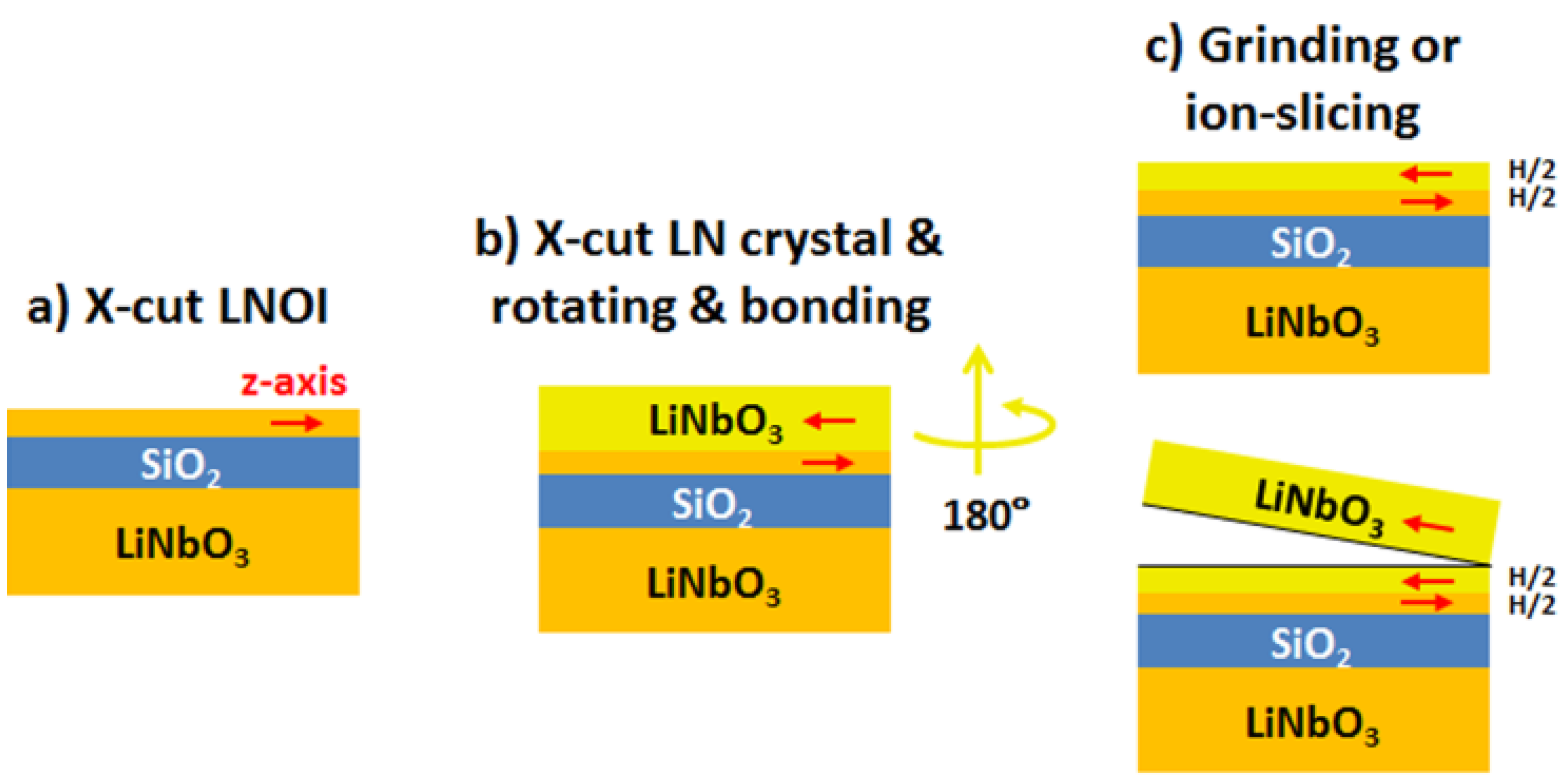
As mentioned above, the weak electric field overlap between two different modes strongly affects the nonlinear coefficient. This drawback can be circumvented if we introduce alternative layers into LNOI wafers. As shown in
Figure 6, when the top layer of the LNOI wafer is composed of two LN thin films with opposite
z-axes, the structure parity compensates the different parities of the pump mode and the SHG mode. It is known that the fabrication of LN thin film can be done by ion-slicing or grinding processes, both having been maturely developed. Based on the new design of LNOI wafer in
Figure 6, the calculated normal SHG conversion efficiency rises from 4.8 to 260 [%/(
W·cm
2)] (
ρ2 rises from 22 to 161
W−1/2m−1), if all the other geometric parameters are kept the same as in
Figure 5. For the input power of 0.5 W, which is limited by damage threshold of LN (~300 MW·cm
−2) [
30], this gives the expected power of the generated second harmonic of the order of 250 μW. Compared to conventional Ti diffusion and (annealed) proton-exchange techniques for fabrication of waveguides in bulk LN crystal, LNOI techniques could avoid Li
+ deficiency and material phase change induced problems [
32,
33]. Moreover, LNOI and MF techniques bring high-index contrast waveguides, implying abundant dispersion engineering capabilities. In contrast, conventional LN waveguides rely on very low index contrast (Δ
n <0.1), and the waveguide dispersion cannot be efficiently engineered. Considering optical performance of our device under temperature variations, one should take into account temperature dependencies of the refractive indices of LN and fused silica, given by the gradients d
ne/d
T ~3.5/4.1 × 10
−5 K
−1 [
30], and d
n/d
T ~1.1/1.0 × 10
−5 K
−1 [
1] at the pump/SHG wavelength, respectively. Taking into account relatively short interaction distances, we do not expect a strong variation of SHG efficiency with temperature. Detailed investigations of possible temperature related effects are beyond the scope of this work.
Figure 6.
Suggested flow chart for fabrication of alternatively-layered LNOI wafer. Optic axes are indicated by red arrows. All the linear optical properties are identical with ordinary LNOI wafers.
Figure 6.
Suggested flow chart for fabrication of alternatively-layered LNOI wafer. Optic axes are indicated by red arrows. All the linear optical properties are identical with ordinary LNOI wafers.


