1. Introduction
Coherent detection in optical communication was extensively studied in the 80’s and 90’s because of its ability to achieve high receiver sensitivity. But the invention of erbium-doped fiber amplifiers along with its own complexity and other practical deficiencies made coherent optical communication less attractive [
1,
2,
3,
4,
5]. The advancements in high speed digital signal processing (DSP) have revived the interest in coherent communications. Together, they have the potential to increase the spectral efficiency, compensate for linear transmission impairments and also achieve carrier synchronization [
6,
7,
8,
9]. However, it is observed that the received constellation in uncompensated coherent optical links, even after DSP, remains influenced by enhanced noise commonly known as equalization enhanced phase noise (EEPN) [
10,
11,
12,
13,
14,
15,
16]. Various studies have been performed with both simulations and system experiments to evaluate these impairments for different modulations on receiver carrier recovery and adaptive equalizers [
17,
18,
19]. This noise enhancement is shown to be in both phase and amplitude dimensions and will also cause time jitter [
20,
21,
22], which is not observed in systems with ideal dispersion compensation in the optical domain. We recently revisited this phenomenon and show in [
23] with a frequency domain analysis that the EEPN-induced transmission penalty is mainly due to low frequency noise of the local oscillator (LO). Hence, elimination of the frequency noise below a certain cutoff frequency significantly reduces the transmission penalty even in extreme cases. The results were experimentally validated in [
24]. Based on the findings in [
23,
24,
25], a realistic implementation of the mitigation technique was proposed in [
26].
In our recent paper [
27], we presented a rigorous nonlinear and time variant analysis (non-LTI) of the most common system configuration with post-reception electronic dispersion compensation (EDC) followed by carrier phase recovery (CPR). Statistical properties were derived and closed form expressions of the necessary LO linewidth and/or mitigation bandwidth essential for the system design were given. Based on the finding of this paper, the physical origin of EEPN can be understood by considering three different coherent reception scenarios as shown in
Figure 1 above. It is important to note the transmitting laser and the LO laser have an asymmetric relationship with respect to dispersive transmission fiber. The transmitting laser output after the in-phase and quadrature phase (IQ) modulator is multiplied with the dispersive fiber transfer function, while the LO convolves with the same transfer function in the photodetectors (in frequency domain). Thus, it is critical to consider the evolution of the signal from source to destination in order to understand EEPN. In the first scenario of homodyne reception, the time domain electrical signal is modulated on an ideal transmitting laser centered at
f0 using an IQ modulator. This signal is temporally broadened during the transmission over a dispersive fiber. The broadened optical pulse is coherently received using an ideal LO with central frequency
f0 matched to the transmitting laser. The original transmitted pulse is then ideally recovered by the static EDC. Now, if the same broadened optical pulse is received using heterodyne detection with an ideal LO with a central frequency,
f1 shifts from the transmitting laser frequency. The received pulse after coherent reception in this scenario has a broadening equal to the pulse received with homodyne detection, but the pulse is delayed by a factor proportional to the accumulated dispersion and relative frequency difference
f1. The EDC is able to compensate for the dispersion-induced broadening but not the delay induced by the heterodyne detection. However, this delay is not critical in this ideal heterodyne case since the entire symbol sequence suffers the same constant delay, which can be easily compensated. In the last scenario, reception using an LO with a non-zero Lorentzian linewidth is considered. As illustrated by the figure, the coherent reception with this LO will result in reception of a complex superposition of several broadened versions of the pulse, each with an individual delay (and amplitude) proportional to the frequency shift (and amplitude) of the corresponding side band component of the LO laser. Similar to the heterodyne case, the static EDC is able to compensate for the broadening but not the delay of different received versions of the pulse. Thus, the phenomenon of EEPN is reminiscent of multipath interference in radio.
The analysis of origin of EEPN in this specific all-electronic mitigation configuration highlights the important property of asymmetry between the transmitting and receiving laser in such coherent links. Thus, the order in which the all-electronic mitigation is performed is critical for the origin and impact of EEPN in any such link. It is important to note that there are more than one DSP schemes practicable in coherent optical systems with EDC (e.g., [
12,
13]) apart from the one covered in [
27]. The origin and impact of EEPN in such schemes remain unknown. Therefore, an extensive analysis of EEPN in all practicable DSP schemes is crucial for the system designers to make an informative choice.
In this paper, we present a non-LTI analysis of EEPN for all practicable DSP schemes in coherent optical systems with EDC. The analysis reveals that the existence and origin of EEPN depends on the DSP scheme for electronic impairment mitigation. We show that there are only eight DSP schemes that are practicable. Some of these schemes do not result in EEPN, whereas the remaining schemes result in EEPN, and in spite of having different sources, are statistically equivalent. The results that are useful for a system designer to make an informed decision are summarized in the form of a simple look-up table.
This paper is organized as follows. In
Section 2, we discuss practically realizable system configurations with EDC. In
Section 3, we derive time and frequency domain responses for all these configurations. These responses are then utilized to obtain statistical properties of the received signal for all the configurations. In
Section 4, the results that are useful for a system designer to make an informed choice are discussed and summarized. The conclusions are finally drawn in
Section 5.
2. Practicable Schemes Employing All-Electronic Impairment Mitigation
In this section, we discuss possible implementations of a coherent optical system utilizing all-electronic impairment mitigation. For the analysis, without loss of generality, we utilize the base band equivalent representation of the system configurations. A generalized system configuration for coherent optical systems employing all-electronic impairment mitigation is shown in
Figure 2. In coherent digital communications, the information is encoded in phase and/or amplitude to achieve high spectral efficiency, depending on modulation format, for each polarization. In the following analysis, without loss of generality, we consider a power normalized representation of the components, so that the net system gain remains unity, independent of the transmitted constellation. In general, the incoming bits are mapped on symmetrically distributed symbols
cn in the complex plane. This results in a symbol train at the rate
Rb/m, where m is the number of bits encoded per symbol and
Rb is the incoming bit rate. The symbol train with symbol period
Ts =
m/Rb is convolved with a pulse shaping filter represented by the Fourier transform pair
to generate a band limited continuous signal with Fourier transform pair
r(
t)
. Then, the band-limited signal is pre-processed in some system configurations to
a priori compensate for the impairments such as channel chromatic dispersion (CD) and/or laser phase noise. The resultant pre-processed signal is modulated on the transmitting laser to generate the output signal. The stochastic base band equivalent representation of the transmitting laser Tx before modulation can be written as
. The transmitter output passes through the all-pass dispersive fiber with the response
. The accumulated dispersion factor
, where
β2 is the group velocity dispersion parameter (GVD),
l is the fiber length,
D is the dispersion coefficient,
c is the speed of light and
f0 is the central optical frequency. Finally, the signal is coherently detected with an LO having a stochastic base band equivalent response of
.
The Optical Transmission Path (OTP) consists of the following operations: modulation on Tx laser, transmission over the fiber link and coherent detection with LO laser. The detected signal is then processed to mitigate the residual impairments, which are not pre-mitigated on the transmitter side. The received signal after post-processing is given by the Fourier transform pair
. The post-processing might also involve filtering with an optimally matched filter in the presence of additive white Gaussian noise (AWGN) to improve signal quality. However, as shown in [
11,
27], the linear filtering has a negligible impact on EEPN because its spectrum is almost identical to the signal spectrum. Hence, in these analyses, without compromising stringency, we neglect the matched filtering operation. The validity of this consideration for all system configurations shall be proved later. Furthermore, as the sampling is a memoryless operation, sampling and then performing CPR is equivalent to performing CPR followed by sampling operation. Thus, a generalized system configuration can be modeled as shown in
Figure 2. In the following analysis, the mitigation transfer functions are modeled as the inverse of the impairment sources assuming ideal compensation. The Fourier transform pair of the mitigation operations for EDC and CPR are given by
and
where “Laser” represents transmitting laser Tx, local oscillator LO, or combined recovery for both Tx and LO given by Tx + LO.
As discussed earlier, due to the possibility of both pre-and post-processing, more than one system configuration is feasible. Therefore, it is imperative to ascertain the practically implementable configuration out of a large number of possibilities that could be conceptualized by permuting the order and position (pre and/or post) of the three mitigation operations that are equalization of the fiber CD, CPR for Tx and CPR for LO. The first option resulting from the permutations is to perform all the impairment mitigation in the pre-processing block. This implies transmitting a pre-distorted signal so that after interacting with the physical source of impairments, the original signal is restored. This configuration is not practically feasible as it would require a priori knowledge of the phase noise information of the LO laser well ahead in time. It would also require an additional spectral channel to transmit this information to the transmitter side with hardware overhead without offering any reasonable advantage. Thus, in the analysis, we discard all permutations requiring CPR of the LO laser to be performed on the transmitter side.
The second obvious permutation option is to perform processing of all impairments after coherent detection. The first choice in this category is to perform equalization followed by combined CPR for both Tx and LO lasers as given by the Scheme 1 (see
Table 1). This is the most common configuration and can be implemented with blind feed-forward mitigation based on the estimation from the received signal only [
7]. The analysis of this configuration for EEPN impact was provided in [
27]. The second feasible scheme in all-post processing category is given by Scheme 2 (see
Table 1). In this configuration the combined carrier phase recovery is performed before dispersion EDC. This configuration can be realized in practice by utilizing the radio frequency (RF) pilot tone as proposed in [
13,
14]. The RF pilot tone contains the combined phase information from both the transmitter and receiver and provides reasonable performance in the back-to-back case. The next possible scheme is given by Scheme 3 (see
Table 1), where the CPR of the LO is performed before the equalizer and the CPR of the Tx after the equalizer. In [
25,
26], it is realized by extracting phase noise information from the LO laser using low bandwidth digital coherence enhancement. Later, the compensation is performed before the equalizer in the post-processing block. A permutation of Scheme 3 could be to perform CPR for the Tx before the equalizer and CPR for LO after the equalizer. This configuration requires estimation of the transmitter phase noise independent of the LO phase noise, which is not possible after reception. Alternatively, it could be implemented by extracting the phase noise information on the transmitter side and then transmitting it together with data to the receiver side. This process is practically unbeneficial for same reason as discussed for performing CPR of LO on the transmitter side.
The other category of configurations is to distribute impairment mitigation operations between pre-and post-processing blocks. The first subset of this category is to perform only the CPR for Tx on the transmitter side and equalization along with CPR for LO on the receiver side. The CPR for Tx in the pre-processing block requires information of the Tx phase noise
a priori to data modulation. This can be realized by using low speed digital coherence enhancement proposed in [
25,
26]. The post-processing can have two variants depicted by Schemes 4 and 5. The post-processing in Scheme 4 can be realized in the similar manner as Scheme 1. Meanwhile, in Scheme 5, it can be realized in the similar manner as Scheme 3. The second subset of this category is to perform the pre-equalization and post CPR for Tx and LO combined (see Scheme 6). This configuration has been discussed and evaluated in [
12]. It is feasible when the system has
a priori information about the route of the optical signal in the network. In the last subset of these configurations, the equalization and the CPR for Tx are performed in the pre-processing block. Meanwhile, the CPR for LO is performed in the post-processing block. This subset (see Schemes 7 and 8) can be practically realized using the digital coherence enhancement proposed in [
25] and [
26]. Schemes such as distributing the amount of EDC between the pre- and post-processing blocks are discarded as they do not provide any additional advantage as shown later. Thus, the study of all possible permutations results in only eight pragmatic configurations summarized in
Table 1.
3. Analysis of EEPN in Practicable System Configurations
In this section, we perform mathematical analysis of all pragmatic configurations (see
Table 1). The analysis provides time and frequency domain responses of the signal influenced by EEPN. Please note that the extended explanation on the derivations of the time domain responses from the frequency domain along with the statistical properties and parameters can be found in [
27].
3.1. Analysis of Scheme 1
Scheme 1 corresponds to the specific realization of
Figure 2 in which equalization is performed in the post-processing block followed by combined CPR for Tx and LO as given in
Table 1. The frequency domain response of the received signal is then given by
where
and the combined CPR
. Performing the operation in Equation (1) in the order of their physical occurrence, due to a non-associative relationship between multiplication and convolution, we obtain
The frequency domain analysis reveals that the linear accumulated channel dispersion, i.e., , is compensated by the linear channel equalizer . However, the intermixing of side bands of the dispersed signal and the LO output in the intensity sensitive photodetectors are not compensated for in the linear equalizer, which results in an enhancement of noise.
Taking the inverse Fourier transform (IFT) of Equation (2) gives the time domain response as
We can observe from Equation (3), that each side band component of the LO demodulates a delayed version of the transmitted signal
r(t). The delay is proportional to its frequency component relative to the central frequency (zero in the base band equivalent case). Thus, EEPN is caused by the interference of these multiple delayed versions of the original signal
r(t) with itself. For digital modulations,
then Equation (3) can be written as
In Equation (4), n = 0 gives the original transmitted symbol along with intra symbol interference, while n ≠ 0 corresponds to inter symbol interference.
Performing the statistical analysis by following the steps given in [
27] indicates that the received signal impaired by EEPN is zero mean with variance
3.2. Analysis of Scheme 2
Scheme 2 corresponds to the specific realization of
Figure 2 with only post-processing in the order given in
Table 1. The frequency domain response of the received signal is given by
where
and the combined CPR
. Performing the operations in Equation (6) we obtain
In this case, the linear accumulated channel dispersion i.e., , is also compensated by the linear channel equalizer and the frequency noise of the LO is compensated by the corresponding CPR. The role of the LO laser in this case is substituted by that of the Tx CPR. In an ideal case, it is the complex conjugate of the Tx laser phase noise.
Taking the IFT of Equation (7) gives the time domain response as
We can observe from Equation (8), that each side band component of the Tx CPR effectively demodulates a delayed version of the transmitted signal
r(t). The delay is proportional to its frequency component relative to the central frequency (zero in the base band equivalent case). For digital modulation, Equation (8) can be written as
In Equation (9),
n = 0 gives the original transmitted symbol along with intra symbol interference, while
n ≠ 0 corresponds to inter symbol interference. The statistical analysis shows that Scheme 2 has identical statistical properties as Scheme 1, except for the fact that in Scheme 2, the role of the LO laser is replaced by the transmitting laser CPR, resulting in the variance
3.3. Analysis of Scheme 3
Scheme 3 corresponds to the specific realization of
Figure 2 in which the CPR for LO in the post-processing is performed before equalization and the CPR for the Tx laser after it, as given in
Table 1. The frequency domain response of the received signal is given by
where
. The operations in Equation (11) are performed in the order of their physical occurrence. We observe that all mitigation functions ideally compensate the corresponding impairments. Thus, the received signal in an ideal case is equal to the transmitted signal
r(t), resulting in zero EEPN. Since this scheme does not have EEPN ideally, the mean and variance due to EEPN are both zero.
3.4. Analysis of Scheme 4
Scheme 4 corresponds to the specific realization of
Figure 2 with Tx CPR performed in the pre-processing block and LO CPR and equalization in the post-processing block in the order given in
Table 1. The frequency domain response of the received signal is given by
In Equation (12), the phase noise from the transmitter is compensated by the pre-processing CPR for the transmitting laser. Performing the operations in Equation (12), we obtain
Taking the IFT of Equation (13) gives the time domain response, which is equal to the received signal in Scheme 1 for an ideal transmitting laser, as can be seen from Equation (4)
We can observe from Equation (14), each side band component of the LO demodulates a delayed version of the transmitted signal
r(
t). The delay is proportional to its frequency component relative to the central frequency (zero in the base band equivalent case), similar to Scheme 1. For digital modulation, Equation (14) can be written as
In Equation (15), n = 0 gives the original transmitted symbol along with intra symbol interference, while n ≠ 0 corresponds to inter symbol interference. The source of EEPN in this scheme is LO laser similar to Scheme 1. Thus, performing the statistical analysis of the received signal yields the variance and mean equal to that obtained in Scheme 1.
3.5. Analysis of Scheme 5
Scheme 5 corresponds to the specific realization of
Figure 2 consisting of pre-processing for Tx laser and post-processing for LO laser along with EDC in the order given in
Table 1. The frequency domain response of the received signal is
In Equation (16), similar to Scheme 3, all mitigation functions ideally compensate the corresponding, resulting in no EEPN in an ideal compensation scenario.
3.6. Analysis of Scheme 6
Scheme 6 corresponds to the specific realization of
Figure 2 with pre-EDC and post carrier phase recovery. The frequency domain response of the received signal is
where the combined CPR
. In this case, the CPR of the LO compensates for the LO phase noise, and the system is influenced mainly by the transmitter phase noise. Performing the operation in Equation (17) in the order of their physical occurrence we obtain
In this scheme, the equalizer behaves as the source of CD, which is compensated by fiber dispersion with conjugate response. Thus, the EEPN is generated at the modulator with Tx laser as the source.
Taking the IFT of Equation (18) gives the time domain response as
We can observe from Equation (19) that each side band component of the Tx generates a delayed version of the transmitted signal
r(t). The delay is proportional to its frequency component relative to the central frequency (zero in the base band equivalent case). For digital modulation, Equation (19) can be written as
In Equation (20),
n = 0 gives the original transmitted symbol along with intra symbol interference, while
n ≠ 0 corresponds to inter symbol interference. Performing the DSP as per Scheme 6 results in the received signal variance given by
It can be seen that for this Scheme, the variance of the received signal is equivalent to that obtained in Schemes 1, 2 and 4. The only difference is that in this Scheme, the contributing sources of EEPN are Tx laser and pre-EDC block, resulting in a change of sign of the accumulated dispersion in the variance.
3.7. Analysis of Scheme 7
Scheme 7 corresponds to the specific realization of
Figure 2 consisting of pre-processing for both EDC and Tx laser in the given order followed by post-processing for LO as given in
Table 1. The frequency domain response of the received signal is given by
Performing the operations in Equation (22), we see that similar to Schemes 3 and 5, this scheme ideally does not result in EEPN.
3.8. Analysis of Scheme 8
Scheme 8 corresponds to the specific realization of
Figure 2 consisting of pre-processing for both Tx laser and EDC in the given order followed by post-processing for LO as given in
Table 1. The frequency domain response of the received signal is given by
where
. In this case, as in Scheme 6, the CPR of the LO compensates for the LO phase noise, and the system is influenced mainly by the transmitter phase noise. Performing the operation in Equation (23) in the order of their physical occurrence we obtain
The equalizer behaves as the source of CD, which is compensated by fiber dispersion with conjugate response. Taking the IFT of Equation (24) gives the time domain response as
We can observe from Equation (25) that each side band component of the Tx laser generates a delayed version of the transmitted signal
r(t). The delay is proportional to its frequency component relative to the central frequency (zero in the base band equivalent case). For digital modulation Equation (25) can be written as
In Equation (26), n = 0 gives the original transmitted symbol along with intra symbol interference, while n ≠ 0 corresponds to inter symbol interference.
In this case, similar to Scheme 6, the contributing sources are Tx laser and the pre-EDC module on the transmitter side. The LO laser phase noise is ideally compensated with a corresponding CPR. Thus, performing the statistical analysis of the received signal yields the variance and mean equal to those obtained in Scheme 6.
It is interesting to note that in all the cases resulting in EEPN, it could be observed from the frequency domain response that the noise spectrum is a slightly broadened version of the signal spectrum
R(f). The broadening is governed by the linewidth of the laser, which is normally negligible compared to the signal baud rate. This results in an EEPN spectrum almost identical to the signal spectrum. Thus, the matched filtering has negligible influence on the EEPN noise as shown in [
11,
27].
4. System Design Aspects
It is essential for the system designer to be able to estimate the impact of EEPN for different system configurations in order to make an informed choice. The system designer can either opt for a system configuration with tolerable penalty or a configuration that allows for mitigation of EEPN. In case of the system configurations resulting in EEPN, it is important to know the required linewidth to limit the penalty below a certain limit. While in the configuration that facilitates EEPN mitigation (see Schemes 3, 5 and 7), it is essential to know the EEPN mitigation bandwidth so as to limit the penalty below a certain limit in a practical implementation.
The statistical properties and parameters of the received stochastic signal for all eight practicable schemes are obtained from the responses derived in
Section 3.
Table 2 summarizes all the useful information related to EEPN that one needs to know for a given configuration, in order to make an informed choice. The first column in the table provides the identification code of a given scheme. The second column gives the source of EEPN in a given configuration, if any. The variance of the received signal influenced by EEPN is given in column three. Finally, the last column states the required parameter in order to design the system with given digital impairment processing configuration. In Schemes 1, 2, 4, 6 and 8, it is essential for the system designer to know the tolerable linewidth to limit the EEPN penalty below a certain limit
p dB. The analytical expression of tolerable linewidth, for systems utilizing Lorentzian linewidth laser and Nyquist pulse shaping, in terms of system specification is given by [
27],
where OSNRref_inband is the reference in band OSNR. Similarly, the mitigation bandwidth in Schemes 3, 5 and 7 utilizing a Lorentzian linewidth laser to limit penalty below p dB, for a general modulation format is given by [
27].
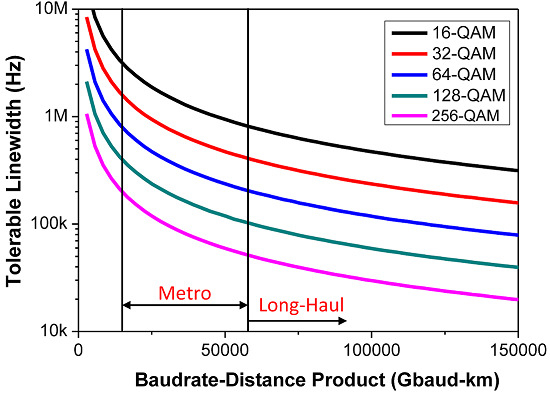
Figure 3a depicts the tolerable linewidth for 1 dB OSNR penalty
versus the Baudrate-Distance product for higher order constellations. It can be observed that the tolerable linewidth falls sharply with increase in the modulation order and/or Baudrate-Distance Product, thus, imposing strict requirements on the laser source responsible for EEPN in a given configuration.
Figure 3b shows the OSNR penalty
versus ideally required mitigation bandwidth for different modulation order in links utilizing Scheme 3, 5 or 7 for laser linewidth equal to 4 MHz. It can be seen that the achievable OSNR penalty due to residual EEPN improves exponentially with an increase in the mitigation bandwidth.
In all the cases, EEPN is due to intermixing of the side band of the dispersed signal with that of the laser phase noise in the multiplication operation. The analysis shows that EEPN generation depends on the relative order of CPRTx, EDC and CPRLO and OTP. LO laser is the source of EEPN only in Schemes with EDC in the post-processing block and when the carrier recovery of LO is performed after EDC (see Schemes 1 and 4). In other schemes resulting in EEPN (see Schemes 2, 6 and 8), EEPN is due to interaction of the dispersed signal with the Tx laser phase noise or its conjugate. Schemes 3, 5 and 7 do not result in EEPN as ideal impairment compensation avoids interaction of the dispersed signal with laser phase noise. Finally, as shown in the previous section, all of the five configurations resulting in EEPN are statistically equivalent. Thus, the distributing amount of the impairment mitigation, such as EDC between pre- and post-processing blocks, does not provide any additional advantage due to this statistical equivalence.

 ,
, 


