Article

Design Study of Time-Preserving Grating Monochromators for Ultrashort Pulses in the Extreme-Ultraviolet and Soft X-Rays

1
Institute of Photonics and Nanotechnologies, National Research Council of Italy, via Trasea 7, I-35131 Padova, Italy
2
Department of Information Engineering, University of Padova, via Gradenigo 6/B, I-35131 Padova, Italy
*
Author to whom correspondence should be addressed.
Photonics 2017, 4(1), 14; https://doi.org/10.3390/photonics4010014
Submission received: 30 January 2017 / Revised: 23 February 2017 / Accepted: 27 February 2017 / Published: 1 March 2017
(This article belongs to the Special Issue Extreme UV Lasers: Technologies and Applications)

Abstract

:
The design of grating-based instruments to handle and condition coherent ultrafast pulses in the extreme-ultraviolet is discussed. The main application of such instruments is the monochromatization of high-order laser harmonics and free-electron-laser pulses in the femtosecond time scale. Broad-band monochromators require the use of diffraction gratings at grazing incidence. A grating can be used for the spectral selection of ultrashort pulses without altering the pulse duration in a significant way, provided that the number of illuminated grooves is equal to the resolution. We discuss here the design conditions to be fulfilled by a grating monochromator that does not increase the pulse duration significantly longer than the Fourier limit.

1. Introduction

The developments in laser technology over the last decades have led to the generation of optical pulses as short as a few femtoseconds, providing a unique tool for high-resolution time-domain spectroscopy that has revolutionized many areas of science [1,2]. While femtosecond optical lasers have offered unique insights into ultrafast dynamics, they are limited by the fact that the structural arrangement and motion of nuclei are not directly accessible from measured optical properties. This scientific gap has been filled by the availability of ultrafast pulsed sources in the extreme-ultraviolet (XUV) and soft X-rays, such as high-order laser harmonics (HHs) and free-electron-lasers (FELs), that make it possible to apply time-resolved spectroscopic techniques in the X-rays [2]. HHs are typically generated when very intense ultrashort laser pulses are focused on a gas jet/cell. They are used worldwide as table-top laboratory sources for the investigation of matter with femtosecond [3] and attosecond resolution [4,5,6,7]. FEL running user facilities generate spatially coherent UV/X-ray radiation with characteristics similar to the light from optical lasers, ultrashort time duration and an increase of 6–8 orders of magnitude on the peak brilliance with respect to third-generation synchrotrons [8,9,10,11].
The HH spectrum is generally described as a sequence of peaks corresponding to the odd harmonics of the fundamental laser frequency with an intensity distribution characterized by a plateau whose extension is related to the wavelength and intensity of the driving laser. Since multiple orders of high harmonics are generated coaxially with the fundamental laser pulses, the application to time-resolved spectroscopy often requires a suitable monochromatizing system to select a single harmonic and reject the adjacent orders and the laser radiation. Furthermore, monochromatization may be important for imaging applications where high spectral purity is required [12,13]. Some of the existing FEL beamlines have grating monochromators either to increase the spectral purity of the source or to select the harmonics of the FEL emission and filter out the fundamental [14,15,16]. Also, zone plates may be used for the monochromatization of ultrashort pulses, especially for high energies. Zone-plates monochromators are used in femtoslicing facilities with residual pulse elongation of a few tens of femtoseconds [17,18,19].
The simplest way to obtain the spectral selection of ultrashort pulses is the use of a multilayer mirror which does not alter the temporal duration of the pulse up to fractions of femtosecond, is very efficient and can be used at normal incidence for tight focusing [20,21]. However, multilayer optics have two main drawbacks: the reflectivity curve is rather broad, therefore they cannot be used for high resolution, and they are not tunable, therefore different multilayer mirrors have to be adopted to operate the monochromator in a broad band [22].
Grating monochromators give tunability in a broad band and high spectral resolution. The monochromator has to ideally preserve the temporal duration as short as in the generation process. However, a grating introduces a tilt of the pulse-front because of diffraction, since each ray that is diffracted by two adjacent grooves is delayed by , where m is the diffraction order and λ the wavelength. The total tilt of the pulse-front, i.e., the difference in the optical paths of the diffracted beam from the source to the image, is |m|λN, where N is the number of the illuminated groves. For example, a 200 gr/mm grating illuminated by radiation at 30 nm over a surface of 10 mm gives a tilt of 200 × 10 × 0.03 = 60 µm, i.e., 200 fs.
There are two options in designing a monochromator for ultrafast pulses, namely the single-grating design [23] or the double-grating configuration [24]. In the first case, adopting a single-grating design, a residual pulse-front tilt has to be accepted at the output of the monochromator. In the second case, the design consists of a pair of gratings to compensate for the pulse-front tilt. The first grating is demanded to perform the spectral selection on an intermediate slit, and the second grating compensates for the pulse-front tilt of the monochromatic diffracted beam, giving an output pulse with ideally no tilt. Double-grating monochromators have demonstrated a temporal resolution higher than 10 fs [25,26,27,28]. The choice between the two configurations has to be performed as a trade-off between efficiency and simplicity, that are maximized in the single-grating design, and temporal resolution, that is maximized in the double-grating design.
Let us concentrate on the single-grating configuration to identify the condition to have the minimum pulse-front tilt from a diffraction grating. For a given bandwidth ∆λ, the pulse duration ∆τ has a lower limit given by the Fourier relation. For a Gaussian profile with no modulation of either phase or frequency, the Fourier limit is expressed by the relation
Δ τ = 2 ln 2 π c λ 2 Δ λ 0.44 c λ 2 Δ λ
where ∆τ is the half-height pulse duration, λ is the central wavelength, ∆λ is the half-height spectral width and c is the speed of light in vacuum.
The pulse-front tilt depends on the number of grooves involved in the diffraction process. Once the required resolution R = λ/∆λ at the output of the monochromator has been defined, the Rayleigh criterion states that the minimum number of grooves Nmin that have to be involved in the diffraction to support such a resolution is |m|Nmin = λ/∆λ. The corresponding half-width variation of the optical paths at the grating output is ∆OPmin ≅ ½ |m|λNmin = ½ λ2/∆λ. It follows that the diffraction from a grating gives a lower limit for the tilt of the pulse-front that is
Δ τ G , min 0.5 c λ 2 Δ λ .
This value is close to the Fourier limit given by Equation (1). Therefore, the single-grating design can be adopted for the monochromatization of ultrashort pulses without altering the pulse duration beyond the Fourier limit in a significant way, provided that the number of illuminated grooves times the diffracted order is equal to the actual resolution.
In this paper, we discuss the design of single-grating monochromators applied to ultrafast pulses in the XUV and soft X-rays. The general design conditions to fulfill the requirements on spectral resolution and minimum pulse-front tilt will be defined. As a test case, the design will be applied to the monochromatization of HHs generated in a typical laboratory setup to identify advantages and drawbacks of the configuration.

2. Single-Grating Monochromators for Ultrashort Pulses

Single-grating monochromators for ultrafast pulses aim to perform the spectral selection in the simplest configuration, using a grating as the dispersive element and tolerating a residual pulse-front tilt at the output.
Grazing-incidence diffraction gratings may be used in two different geometries: the classical-diffraction mount (CDM) and the off-plane mount (OPM). The CDM is shown in Figure 1a. The grating equation is sin α − sin β = mλσ, where α is the incidence angle, β is the diffraction angle and σ is the groove density. The OPM differs from the CDM in that the incident and diffracted wave vectors are almost parallel to the grating grooves, as shown in Figure 1b. The grating equation is sin γ (sin µ + sin ν) = mλσ, where γ is the altitude angle, i.e., the angle between the direction of the incoming rays and the direction of the grooves; µ and ν are the azimuth angles of the incidence and diffracted rays, defined to be zero if they lie in the plane perpendicular to the grating surface and parallel to the grooves. The OPM gives higher throughput than the CDM, since it has been theoretically demonstrated and experimentally measured that the OPM peak diffraction efficiency is close to the reflectivity of the coating at the altitude angle [29,30]. Both geometries have still been applied to the realization of ultrafast monochromators for HHs in the XUV [31,32,33,34].
Since the gratings in the OPM monochromators are operated in parallel light, we will compare the two configurations with plane gratings. The optical schematics are shown in Figure 2. The first mirror M1 acts as the collimator, the second mirror M2 acts as the condenser. The magnification factor is the ratio between the output arm q of M2, i.e., the distance between the mirror center and the exit slit, and the input arm p of M1, i.e., the distance between the entrance slit and the mirror center. The wavelength scanning is performed by rotating the grating around an axis tangent to its vertex and parallel to the grooves.
In the case of CDM, the scanning is done at a constant subtended angle and the grating is rotated following the relation
α = K 2 + arcsin [ m λ σ 2 cos ( K / 2 ) ]
where K is the subtended angle: K = α + β.
In the case of OPM, the altitude angle γ is kept constant, the grating is operated in the condition µ = ν and the azimuth µ is varied following the relation
μ = arcsin [ m λ σ 2 sin γ ]

3. Pulse-Preserving Monochromators

In the following, we will discuss the geometrical issues to design a monochromator for ultrafast pulses with negligible pulse front-tilt for the two geometries, that means R = λ/∆λ = |m|N. The resolution at the output of the monochromator depends on the spectral dispersion and on the width of the slits. Let us suppose that the width of the exit slit, WOUT, is equal to the width of the input source, S, as imaged at the output of the monochromator. This is the minimum width that has to be kept to guarantee the complete transmission of the diffracted beam. In the case of a slit monochromator—the schematics are shown in Figure 2S is the width of the input slit. In the case of a slitless monochromator—the instrument normally used for HHs—S is the full size of the source.
In the CDM geometry, the input source S is imaged at the output as WOUT = S cos α/cos β q/p, where cos α/cos β is the grating anamorphism and q/p is the geometric magnification. The resulting output bandwidth is
Δ λ = W O U T cos β | m | σ q = S cos α | m | σ p
The number of illuminated grooves is N = 2Dpσ/cos α, where D is the half-width beam divergence at the input. The condition λ/∆λ = |m|N to have the minimum pulse-front tilt is expressed by
D S = λ 2
that is very close to the relation for a diffraction-limited source: θS = 2λπ−1 for a Gaussian beam. It can be shown that the same condition applies also to CDM designs with concave gratings, where p and q are respectively the grating entrance and exit arms.
The OPM, when applied to ultrafast pulses, is generally used in the geometry µ ≤ 20°, i.e., cos µ ≈ 1 [35]. In this case, the input source is imaged at the output as WOUT = S q/p. The resulting output bandwidth is
Δ λ = W O U T 1 | m | σ q = S 1 | m | σ p
The number of illuminated grooves is N = 2Dpσ. The condition to have the minimum pulse-front tilt is again expressed by Equation (6).
If can be concluded that the minimum pulse front-tilt that is given by a single-grating monochromator is reached when the source is diffraction-limited and the instrument is designed to give the required resolution on an exit slit that is as wide as the projection of the input source after diffraction. If these conditions are verified, the monochromator is defined to be pulse-preserving, since the pulse-front tilt is comparable to the Fourier limit calculated for the output bandwidth.
In order to illustrate the design procedure, we discuss as a test case the design of a XUV time-preserving monochromator using the CDM geometry for the 20–40 eV region with a target energy bandwidth of 50 meV at 30 eV. The input beam is supposed to be Gaussian with S = 100 μm and half-width divergence calculated as D = 2λS−1π−1.
The groove density is assumed to be σ = 600 gr/mm, that is a standard value for commercially available gratings. The grating is operated at the first external order, i.e., β > α, and the subtended angle is K = 152°. The entrance arm is calculated through Equation (5) as p = 700 mm to give the required resolution at 30 eV. The exit arm does not influence the resolution, as soon as the width of the exit slit is chosen according to WOUT = S cos α/cos β q/p. Note that the slit width has to be varied with the wavelength, since incidence and diffraction angles are changing. The parameters of the CDM grating are summarized in Table 1. The exit arm has been assumed to be equal to the entrance arm in order to minimize the residual optical aberrations. The resulting performances are shown in Figure 3. The output bandwidth is increasing with the energy, as can be verified through Equation (5). The pulse-front tilt is reduced when the energy is increased, since the beam divergence is decreasing and less grooves are illuminated, and also since the wavelength is decreasing. The pulse-front tilt is slightly higher but comparable to the Fourier limit, the difference being lower at the higher energies.
It can be shown that the operation of the grating at internal order, that is, β < α, gives very similar results in terms of variation of bandwidth and pulse-front tilt with the energy.
Let us apply the OPM geometry to the design of a monochromator with the same requirements. The groove density is assumed to be σ = 1200 gr/mm. The grating is operated at an altitude of γ = 6°. The entrance arm is calculated through Equation (7) as p = 1200 mm. The exit arm does not influence the resolution, as soon as the width of the exit slit is chosen according to WOUT = S q/p. The parameters of the OPM grating are summarized in Table 1. Also in this case, the exit arm has been assumed to be equal to the entrance arm in order to minimize the residual optical aberrations. The resulting performances are shown in Figure 4 and are very similar to the CDM geometry. Also in this case, the output bandwidth is increasing with the energy and the pulse-front tilt is reduced when the energy is increased. Again, the pulse-front tilt is comparable to the Fourier limit, although higher, the difference being lower at the higher energies.
The performances, in terms of temporal response, can be increased if the grating is used in a narrower band, e.g., 25–40 eV, and a second grating with lower groove density is added to scan energies lower than 30 eV.
It can be concluded that for a single-grating monochromator, the pulse-front tilt given by the diffraction is not negligible, although it may be close to the Fourier limit for diffraction-limited sources.

4. Single-Grating Monochromators for HHs

In real applications, a trade-off has to be accepted between high energy resolution and high temporal resolution when single-grating designs are adopted, giving a pulse-front tilt that is definitely beyond the Fourier limit. Here, we discuss the optical design of a grating monochromator for HHs. Monochromators and spectrometers for HHs are typically operated without an entrance slit [36], with the HH source itself being very small in extension. The HH divergence in the plateau region depends on the generation geometry [37,38,39,40,41] and is typically in the few-mrad range.
Here, we assume to deal with the 14–45 eV region, that is the region normally covered by HHs generated in argon, with an average energy bandwidth of 100 meV. This is a typical requirement for pump–probe experiments on solid-state samples. We will design a monochromator using the OPM geometry.
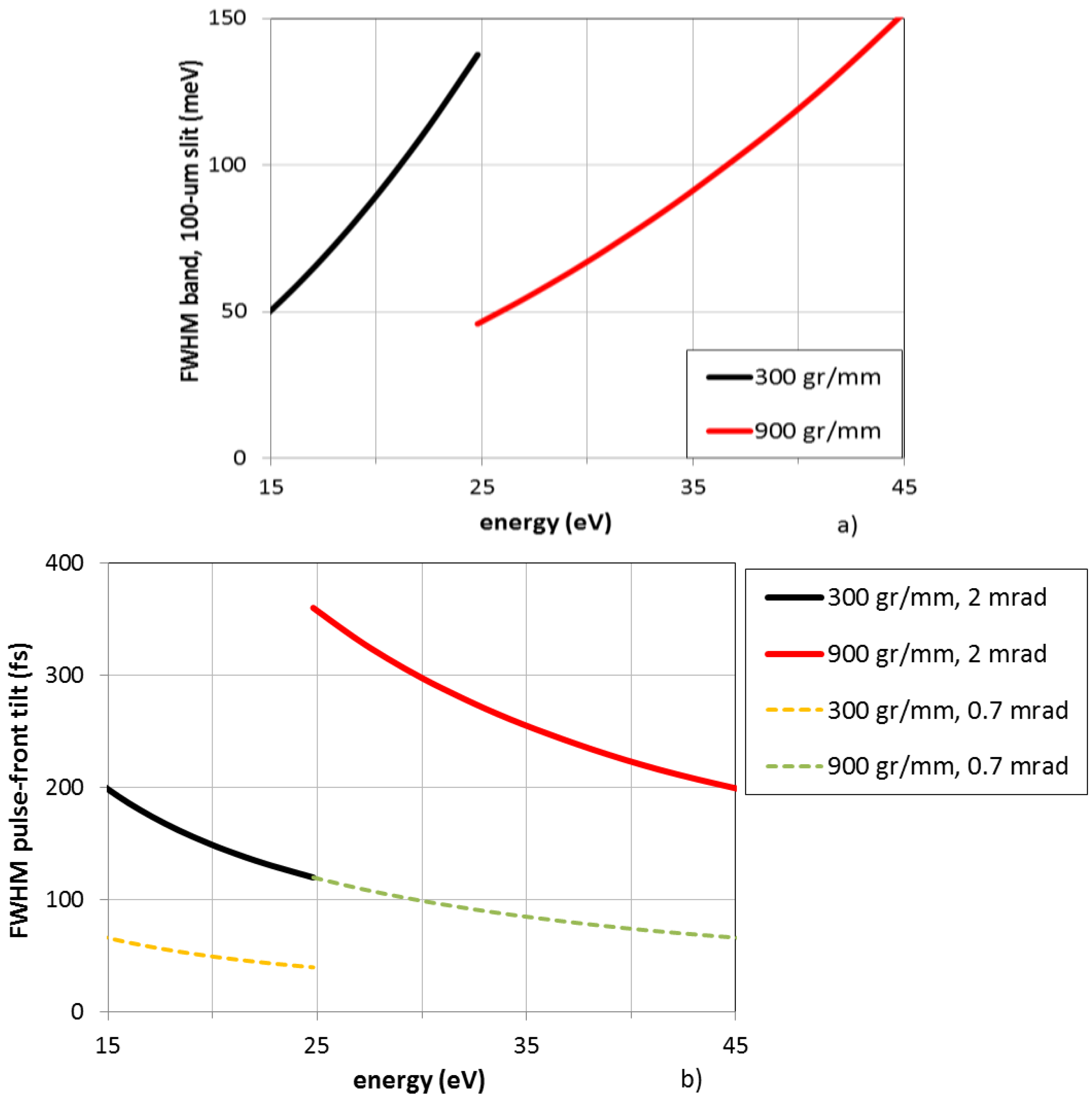
The design of the monochromator starts from the width of the exit slit to be used to obtain the required resolution, that is here assumed to be 100-µm wide. Then, the grating groove density and the output arm are consequently chosen. In the setup discussed here, the whole energy region is covered by two gratings with an output arm of 1200 mm: (1) 300 gr/mm for the 15–25 eV interval; (2) 900 gr/mm for the 25–45 eV interval. The energy bandwidth is shown in Figure 5a.
The pulse-front tilt depends on the grating parameters, on the source divergence and on the length of the input arm. Here, we assume a full-width-at-half-maximum (FWHM) divergence of 2 mrad, that is a typical value for HHs generated in argon with few-mJ-energy laser pulses. Once the grating and the source divergence have been given, the only parameter that can be used to control the pulse-front tilt is the length of the input arm: the shorter the length, the lower the tilt. However, there is a limit in shortening the length, since the resulting source magnification, i.e., q/p, has to be lower than the width of the exit slit, otherwise the resolution is decreased. For HHs generated with few-mJ-energy laser pulses as available in many laboratories, the laser spot size in the focus is of the order of 150 µm (calculated assuming 1014 W/cm2 peak intensity, 30 fs pulse duration and 2 mJ pulse energy), therefore the XUV source size, assumed to be slightly smaller than this value, is expected in the range ≈100 µm. Using a 100-µm slit, the design magnification is unity, that is, p = 1200 mm. The resulting pulse-front tilt is shown in Figure 5b. It is in the 120–350 fs interval, definitely higher than the 18-fs Fourier limit for 100 meV. A way to reduce the tilt is to limit the beam aperture in the direction perpendicular to the grooves, in order to reduce the number of grooves involved in the diffraction. The corresponding reduction of the tilt is linear with the accepted aperture. In the case here discussed, a tilt below 100 fs is obtained if the accepted aperture is reduced by a factor 3, that is, 0.7 mrad FWHM. This is also plotted in Figure 5b. Obviously, when the aperture is closed, the photon flux is also reduced by the same factor.
The monochromator parameters are finally summarized in Table 2.
This typical case illustrates the trade-off that has to be accepted among energy resolution, temporal resolution and photon flux when designing monochromatic beamlines for HHs in the XUV, in order to optimally fit the experimental requirements. Obviously, the configuration with two gratings corrects for the residual pulse-front tilt, but with a more complex design.

5. Single-Grating Monochromators for FELs

The same design considerations apply to monochromators for FEL facilities. Monochromatic beamlines using the single-grating design for the X-ray region are still in operation at FELs, as is the case for the soft x-ray materials science (SXR) instrument at the Linac Coherent Light Source (LCLS) FEL-facility [42]. The beamline is operated at energies higher than 500 eV, i.e., λ < 2.5 nm, with a source divergence of 16 µrad FWHM, giving a resolution of ≈5000 from 500 to 1000 eV and lower for higher energies. The optical design uses the varied-line spacing (VLS) grating monochromator. The pulse-front tilt is of the order of a few tens of femtoseconds (estimated to be 30 fs at 800 eV), that is definitely within the requirements to be less than 100 fs.
When dealing with FEL sources in the XUV or soft X-rays, the pulse-front tilts that are obtained from gratings for medium resolution (R ≈ 1000–3000) are of the order of several hundreds of femtoseconds or even few picoseconds, since the number of illuminated grooves is definitely larger than R, with the divergence being much larger than for X-rays. If the VLS design is adopted for a monochromator for the upcoming FLASH II facility in the 40–200 eV range, it has been shown that a grating for an average resolution of 2000 gives a pulse-front tilt from 0.2 to ≈2 ps, that is reduced to less than 10 fs for the double-grating design [43].
Also in the case of monochromatic beamlines for FEL sources, a trade-off that has to be found between energy resolution and temporal resolution to optimally fit the experimental requirements. While in the X-rays the single-grating design applied to FELs has been demonstrated to give medium-to-high resolution with pulse-front tilts usable for ultrafast experiments, this is not trivial at all in the XUV, where the double-grating configuration should be considered.

6. Conclusions

The time response of single-grating monochromators has been analyzed, in particular regarding its application to ultrashort femtosecond pulses in the extreme-ultraviolet and soft X-rays, such as radiation from high-order laser harmonics or free-electron lasers. It has been shown that time-preserving monochromators can be realized in a single-grating configuration if the number of illuminated grooves is the minimum for a given resolution, so that the pulse-front tilt is close to the Fourier limit for such a resolution. Some design cases have been discussed to illustrate the trade-off that has to be found among energy resolution, temporal resolution and photon flux in order to optimally fit the experimental requirements.

Author Contributions

L.P. conceived the configurations here discussed. F.F., N.F. and P.M. contributed to the optical simulations. L.P. wrote the paper.

Conflicts of Interest

The authors declare no conflict of interest.

References

  1. Marciak-Kozlowska, J.; Kozlowski, M. From Femto-To Attoscience and Beyond; Nova Science Publisher: Hauppauge, NY, USA, 2009. [Google Scholar]
  2. Diels, J.C.; Rudolph, W. Ultrashort Laser Pulse Phenomena, 2nd ed.; Elsevier: London, UK, 2006; pp. 277–394. [Google Scholar]
  3. Jaeglè, P. Coherent Sources of XUV Radiation; Springer: New York, NY, USA, 2006; pp. 277–344. [Google Scholar]
  4. Krausz, F.; Ivanov, M. Attosecond physics. Rev. Mod. Phys. 2009, 81, 163–234. [Google Scholar] [CrossRef]
  5. Sansone, G.; Poletto, L.; Nisoli, M. High-energy attosecond light sources. Nat. Photonics 2011, 5, 655–663. [Google Scholar] [CrossRef]
  6. Gallmann, L.; Cirelli, C.; Keller, U. Attosecond Science: Recent Highlights and Future Trends. Ann. Rev. Phys. Chem. 2012, 63, 447–469. [Google Scholar] [CrossRef] [PubMed]
  7. Krausz, F.; Stockman, M.I. Attosecond metrology: From electron capture to future signal processing. Nat. Photonics 2014, 8, 205–213. [Google Scholar] [CrossRef]
  8. Free-Electron Laser FLASH. Available online: http://flash.desy.de/ (accessed on 30 January 2017).
  9. SACLA (XFEL). Available online: http://xfel.riken.jp/eng/ (accessed on 30 January 2017).
  10. LCLS—Linac Coherent Light Source. Available online: http://lcls.slac.stanford.edu/ (accessed on 30 January 2017).
  11. FERMI. Available online: https://www.elettra.trieste.it/lightsources/fermi.html (accessed on 30 January 2017).
  12. Sekikawa, T.; Okamoto, T.; Haraguchi, E.; Yamashita, M.; Nakajima, T. Two-photon resonant excitation of a doubly excited state in He atoms by high-harmonic pulses. Opt. Express 2008, 16, 21922–21929. [Google Scholar] [CrossRef] [PubMed]
  13. Zurch, M.; Kern, C.; Spielmann, C. XUV coherent diffraction imaging in reflection geometry with low numerical aperture. Opt. Express 2013, 21, 21131–21147. [Google Scholar] [CrossRef] [PubMed]
  14. Martins, M.; Wellhöfer, M.; Hoeft, J.T.; Wurth, W.; Feldhaus, J.; Follath, R. Monochromator beamline for FLASH. Rev. Sci. Instrum. 2006, 77, 115108. [Google Scholar] [CrossRef]
  15. Guerassimova, N.; Dziarzhytski, S.; Feldhaus, J. The monochromator beamline at FLASH: Performance, capabilities and upgrade plans. J. Mod. Opt. 2011, 58, 1480–1485. [Google Scholar] [CrossRef]
  16. Schlotter, W.F.; Turner, J.J.; Rowen, M.; Heimann, P.; Holmes, M.; Krupin, O.; Messerschmidt, M.; Moeller, S.; Krzywinski, J.; Soufli, R.; et al. The soft X-ray instrument for materials studies at the linac coherent light source X-ray free-electron laser. Rev. Sci. Instrum. 2012, 88, 043107. [Google Scholar] [CrossRef] [PubMed]
  17. Heimann, P.A.; Glover, T.E.; Plate, D.; Lee, H.J.; Brown, V.C.; Padmore, H.A.; Schoenlein, R.W. The Advanced Light Source (ALS) Slicing Undulator Beamline. AIP Conf. Proc. 2007, 879, 1195–1197. [Google Scholar]
  18. Brzhezinskaya, M.; Firsov, A.; Holldack, K.; Kachel, T.; Mitzner, R.; Pontius, N.; Schmidt, J.-S.; Sperling, M.; Stamm, C.; Fohlisch, A.; et al. A novel monochromator for experiments with ultrashort X-ray pulses. J. Synchr. Radiat. 2013, 20, 1–9. [Google Scholar] [CrossRef] [PubMed]
  19. Holldack, K.; Bahrdt, J.; Balzer, A.; Bovensiepen, U.; Brzhezinskaya, M.; Erko, A.; Eschenlohr, A.; Follath, R.; Firsov, A.; Frentrup, W.; et al. FemtoSpeX: A versatile optical pump-soft X-ray probe facility with 100 fs X-ray pulses of variable polarization. J. Synchr. Radiat. 2013, 21, 1090–1104. [Google Scholar] [CrossRef] [PubMed]
  20. Wieland, M.; Frueke, R.; Wilhein, T.; Spielmann, C.; Pohl, M.; Kleineberg, U. Submicron extreme ultraviolet imaging using high-harmonic radiation. Appl. Phys. Lett. 2002, 81, 2520–2522. [Google Scholar] [CrossRef]
  21. Mashiko, H.; Suda, A.; Midorikawa, K. Focusing coherent soft-X-ray radiation to a micrometer spot size with an intensity of 1014 W/cm2. Opt. Lett. 2004, 29, 1927–1929. [Google Scholar] [CrossRef] [PubMed]
  22. Poletto, L.; Tondello, G. Time-compensated EUV and soft X-ray monochromator for ultrashort high-order harmonic pulses. Pure Appl. Opt. 2001, 3, 374–379. [Google Scholar] [CrossRef]
  23. Poletto, L.; Frassetto, F. Time-preserving monochromators for ultrafast extreme-ultraviolet pulses. Appl. Opt. 2010, 49, 5465–5473. [Google Scholar] [CrossRef] [PubMed]
  24. Poletto, L. Time-compensated grazing-incidence monochromator for extreme-ultraviolet and soft X-ray high-order harmonics. Appl. Phys. B 2004, 78, 1013–1016. [Google Scholar] [CrossRef]
  25. Poletto, L.; Villoresi, P.; Benedetti, E.; Ferrari, F.; Sansone, G.; Stagira, S.; Nisoli, M. Intense femtosecond extreme ultraviolet pulses by using a time-delay compensated monochromator. Opt. Lett. 2007, 32, 2897–2899. [Google Scholar] [CrossRef] [PubMed]
  26. Poletto, L.; Villoresi, P.; Frassetto, F.; Calegari, F.; Ferrari, F.; Lucchini, M.; Sansone, G.; Nisoli, M. Time-delay compensated monochromator for the spectral selection of extreme-ultraviolet high-order laser harmonics. Rev. Sci. Instrum. 2009, 80, 123109. [Google Scholar] [CrossRef]
  27. Ito, M.; Kataoka, Y.; Okamoto, T.; Yamashita, M.; Sekikawa, T. Spatiotemporal characterization of single-order high harmonic pulses from time-compensated toroidal-grating monochromator. Opt. Express 2010, 18, 6071–6078. [Google Scholar] [CrossRef] [PubMed]
  28. Igarashi, H.; Makida, A.; Ito, M.; Sekikawa, T. Pulse compression of phase-matched high harmonic pulses from a time-delay compensated monochromator. Opt. Express 2012, 20, 3725–3732. [Google Scholar] [CrossRef] [PubMed]
  29. Poletto, L.; Villoresi, P. Time-compensated monochromator in the off-plane mount for extreme-ultraviolet ultrashort pulses. Appl. Opt. 2006, 45, 8577–8585. [Google Scholar] [CrossRef] [PubMed]
  30. Pascolini, M.; Bonora, S.; Giglia, A.; Mahne, N.; Nannarone, S.; Poletto, L. Gratings in a conical diffraction mounting for an extreme-ultraviolet time-delay-compensated monochromator. Appl. Opt. 2006, 45, 3253–3262. [Google Scholar] [CrossRef] [PubMed]
  31. Frassetto, F.; Cacho, C.; Froud, C.A.; Turcu, I.C.; Villoresi, P.; Bryan, W.A.; Springate, E.; Poletto, L. Single-grating monochromator for extreme-ultraviolet ultrashort pulses. Opt. Express 2011, 19, 19169–19181. [Google Scholar] [CrossRef]
  32. Grazioli, C.; Callegari, C.; Ciavardini, A.; Coreno, M.; Frassetto, F.; Gauthier, D.; Golob, D.; Ivanov, R.; Kivimäki, A.; Mahieu, B.; et al. CITIUS: An infrared-extreme ultraviolet light source for fundamental and applied ultrafast science. Rev. Sci. Instrum. 2014, 85, 023104. [Google Scholar] [CrossRef] [PubMed]
  33. Poletto, L.; Miotti, P.; Frassetto, F.; Spezzani, C.; Grazioli, C.; Coreno, M.; Ressel, B.; Gauthier, D.; Ivanov, R.; Ciavardini, A.; et al. Double-configuration grating monochromator for extreme-ultraviolet ultrafast pulses. Appl. Opt. 2014, 53, 5879–5888. [Google Scholar]
  34. Ojeda, J.; Arrell, C.A.; Grilj, J.; Frassetto, F.; Mewes, L.; Zhang, H.; Mourik, F.; Poletto, L.; Chergui, M. Harmonium: A pulse preserving source of monochromatic EUV (30–110 eV) radiation for ultrafast photoelectron spectroscopy of liquids. Struct. Dyn. 2016, 3, 023602. [Google Scholar] [CrossRef] [PubMed]
  35. Poletto, L.; Frassetto, F. Single-grating monochromators for extreme-ultraviolet ultrashort pulses. Appl. Sci. 2013, 3, 1–13. [Google Scholar] [CrossRef]
  36. Poletto, L.; Bonora, S.; Pascolini, M.; Villoresi, P. Instrumentation for analysis and utilization of extreme-ultraviolet and soft X-ray high-order harmonics. Rev. Sci. Instrum. 2004, 75, 4413–4418. [Google Scholar] [CrossRef]
  37. Salières, P.; Ditmire, T.; Perry, M.D.; L’Huillier, A.; Lewenstein, M. Angular distributions of high-order harmonics generated by a femtosecond laser. J. Phys. B. At. Mol. Opt. Phys. 1996, 29, 4771–4786. [Google Scholar] [CrossRef]
  38. Nisoli, M.; Priori, E.; Sansone, G.; Stagira, S.; Cerullo, G.; De Silvestri, S.; Altucci, C.; Bruzzese, R.; de Lisio, C.; Villoresi, P.; et al. High-Brightness High-Order Harmonic Generation by Truncated Bessel Beams in the Sub-10-fs Regime. Phys. Rev. Lett. 2002, 88, 33902. [Google Scholar] [CrossRef] [PubMed]
  39. Takahashi, E.J.; Nabekawa, Y.; Midorikawa, K. Low-divergence coherent soft X-ray source at 13 nm by high-order harmonics. Appl. Phys. Lett. 2004, 84, 4. [Google Scholar] [CrossRef]
  40. Jin, C.; Lin, C.D. Comparison of high-order harmonic generation of Ar using truncated Bessel and Gaussian beams. Phys. Rev. A 2012, 85, 033423. [Google Scholar] [CrossRef]
  41. Ye, P.; Teng, H.; He, X.-K.; Zhong, S.-Y.; Wang, L.-F.; Zhan, M.-J.; Zhang, W.; Yun, C.-X.; Wei, Z.-Y. Minimizing the angular divergence of high-order harmonics by truncating the truncated Bessel beam. Phys. Rev. A 2014, 90, 063808. [Google Scholar] [CrossRef]
  42. Heimann, P.; Krupin, O.; Schlotter, W.F.; Turner, J.; Krzywinski, J.; Sorgenfrei, F.; Messerschmidt, M.; Bernstein, D.; Chalupský, J.; Hájková, V.; et al. Linac Coherent Light Source soft X-ray materials science instrument optical design and monochromator commissioning. Rev. Sci. Instrum. 2011, 82, 093104. [Google Scholar] [CrossRef] [PubMed]
  43. Frassetto, F.; Ploenjes, E.; Kuhlmann, M.; Poletto, L. Time-delay-compensated grating monochromator for FEL beamlines. In SPIE Proceedings 9210, X-ray Free-Electron Lasers: Beam Diagnostics, Beamline Instrumentation, and Applications II; SPIE: San Diego, CA, USA, 2014; Volume 9210. [Google Scholar]
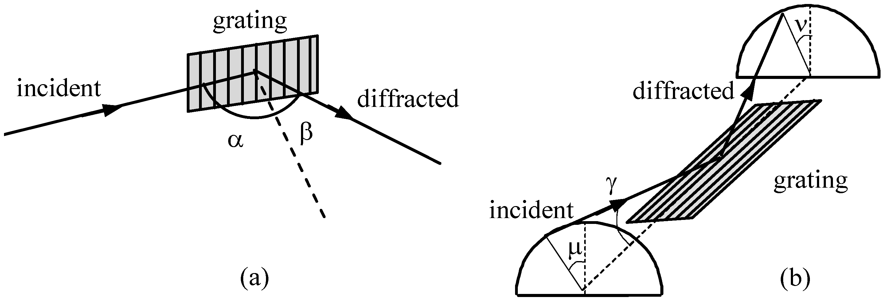
Figure 1. Grating geometries: (a) classical-diffraction mount (CDM); (b) off-plane mount (OPM).
Photonics 04 00014 g001
Figure 2. Monochromator with plane gratings: (a) CDM; (b) OPM. M1 and M2 are respectively the collimating and focusing mirror, G is the grating.
Photonics 04 00014 g002
Figure 3. CDM ultrafast monochromator with a Gaussian diffraction-limited input source, 100 μm full size. The grating parameters are reported in Table 1. (a) Output energy bandwidth; (b) Temporal response of the monochromator: pulse-front tilt and Fourier limit; (c) Width of the exit slit to match the size of the input source as imaged at the output.
Photonics 04 00014 g003
Figure 4. OPM ultrafast monochromator with a Gaussian diffraction-limited input source, 100 μm full size. The grating parameters are reported in Table 1. (a) Energy bandwidth on the exit slit, that has a fixed width of 100-μm; (b) Temporal response of the monochromator: pulse-front tilt and Fourier limit.
Photonics 04 00014 g004
Figure 5. OPM ultrafast monochromator in the 15–45 eV region, 100 meV average bandwidth. The grating parameters are reported in Table 2. (a) Energy bandwidth on the 100-μm exit slit; (b) Pulse-front tilt with 2 mrad and 0.7 mrad full-width-at-half-maximum (FWHM) accepted aperture.
Photonics 04 00014 g005
Table 1. Parameters of a monochromator with a target energy bandwidth of 50 meV at 30 eV.
Spectral Region20–40 eV
CDM GratingSubtended angle152°, external order
Groove density600 gr/mm
Entrance/output arm700 mm
OPM GratingAltitude angle
Groove density1200 gr/mm
Entrance/output arm1200 mm
Table 2. Parameters of a CDM monochromator with a target energy bandwidth of 100 meV in the 15–45 eV interval.
Spectral Region15–45 eV
Energy Bandwidth100 meV
Source Divergence2 mrad FWHM
OPM Gratings2 gratings
Entrance arm1200 mm
Output arm1200 mm
Grating 1Energy region15–25 eV
Groove density300 gr/mm
Grating 2Energy region25–45 eV
Groove density900 gr/mm