A Novel Hexahedron Photonic Crystal Fiber in Terahertz Propagation: Design and Analysis


1
Department of Information and Communication Technology (ICT), Mawlana Bhashani Science and Technology University (MBSTU), Santosh, Tangail 1902, Bangladesh
2
Group of Bio-photomatiχ, Santosh, Tangail 1902, Bangladesh
3
Department of Software Engineering, Daffodil International University, Dhaka 1207, Bangladesh
4
Department of Electrical and Electronic Engineering, Daffodil International University, Dhaka 1207, Bangladesh
*
Author to whom correspondence should be addressed.
Photonics 2019, 6(1), 32; https://doi.org/10.3390/photonics6010032
Submission received: 24 January 2019
/
Revised: 11 March 2019
/
Accepted: 14 March 2019
/
Published: 21 March 2019
(This article belongs to the Special Issue Terahertz Photonics)
Abstract
:A novel hexahedron fiber has been proposed for biomedical imaging applications and efficient guiding of terahertz radiation. A finite element method (FEM) has been applied to investigate the guiding properties rigorously. All numerically computational investigated results for optimum parameters have revealed the high numerical aperture (NA) of 0.52, high core power fraction of 64%, near zero flattened dispersion of 0.5 ± 0.6 ps/THz/cm over the 0.8–1.4 THz band and low losses with 80% of the bulk absorption material loss. In addition, the V–parameter is also inspected for checking the proposed fiber modality. The proposed single-mode hexahedron photonic crystal fiber (PCF) can be highly applicable for convenient broadband transmission and numerous applications in THz technology.
1. Introduction
Nowadays, significant attention has been given to terahertz (THz) wave propagation or spectrum, ranging from 0.1 to 10 THz, due to its numerous practical applications in the field of medical imaging, detection of cancer cell, remote sensing, spectroscopy, oral healthcare, spectroscopy, molecular structure, telecommunication, bio technology, dermatology, security purpose, military and environmental applications [1,2,3]. Different medical diagnosis systems like nonintrusive, minimally intrusive, and intraoperative are largely dependent on THz PCF. With the help of advancement of modern technology, the THz sources and detectors are also updating rapidly. However, to design a reliable, flexible, and low-loss THz waveguide is a challenging issue because of its high material absorption. In addition, the THz waveguides are reliable and bulky on the free space propagation due to the lack of efficient transmission. To overcome the previous reported lack, the researchers, scientists, and pioneers have proposed different types of THz waveguides such as hollow metallic, metallic slot, dielectric metal-coated tubes, parallel-plate waveguides, Bragg fibers, and subwavelength polymer fibers [3,4]. Later, solid core photonic crystal fiber (PCF) has been proposed and gained high absorption loss due to water vapor. Then, microstructure core PCF has been proposed as a THz guiding medium to achieve low loss, high numerical aperture (NA) and better guiding properties.
The first PCF were proposed as an optical waveguide. However, due to the excellent optical performance, it holds many real applications in various areas such as gas sensor [5], chemical sensor [6], pressure sensor [7], salinity and temperature sensor [8], optical multiplexer and demultiplexer [9,10,11], optical power splitter [12], optical filter [13], etc.
In the last several decades, numerous articles have been published to minimize the effective material loss (EML), confinement loss, and scattering loss, and to increase the core power fraction and effective area of THz PCF. In 2013, Islam et al. [14] proposed spiral THz PCF and gained effective area and EML of 1.82 × 10 m and 0.10 cm at 1 THz. The EML of propsed PCF was very high and did not calculate two crucial parameters like V and core power fraction. In 2014, Rana et al. [15] suggested octagonal lattice PCF and gained EML of 0.05 cm and core power of 40% at 1 THz. In 2016, Hasan et al. [16,17] reported hexagonal and square lattice PCFs which gained EML of 0.089 cm and 0.076 cm respectively. However, core power fraction was very low and did not mention some crucial parameters. Earlier in 2017, Ahmed et al. [3] and Sen et al. [2] proposed THz fibers with low power fraction, EML and effective area. None of the articles reported above investigated numerical aperture (NA). In 2017, Sultana et al. [18] reported Zeonex based kagome PCF and gained the NA of 0.48 at 1 THz. However, they did not investigate some crucial parameters like core power fraction, effective area, scattering loss and fiber modality. Thus, based on literature review, there is still a large amount of room to design THz PCF to achieve better guiding properties.
In this letter, a single mode hexahedron PCF has been proposed for efficient delivery of THz applications. The investigated results have revealed the maximum NA of 0.518, near zero group velocity dispersion (GVD) of 0.5 ± 0.6 ps/THz/cm over the 0.8 to 1.4 THz band for optimized structure. In addition, high core power, low scattering, confinement loss and EML have been also gained. The proposed fiber can be practically realized due to its structural simplicity.
2. Design Methodology and Numerical Methods
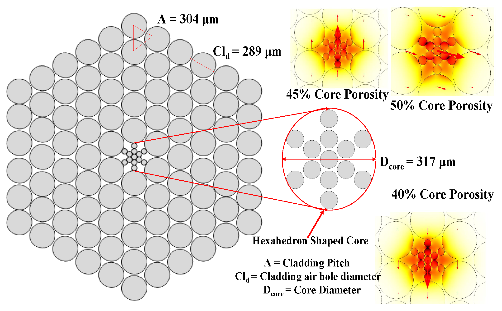
The schematic view of the proposed hexahedron PCF is shown in Figure 1 with proper description and modal intensity. In the cladding region, the air holes are organized in a hexagonal manner where the angular placement of these air holes are followed by the rhythm where . In addition, the core region has been constituted followed by the hexahedron shape. In core and cladding, the diameters of the air holes are 56.8 m and 289 m with an air-filling ratio of 0.88 and 0.95, respectively, which are very sophisticated for fiber fabrication. TOPAS is utilized as hosting materials due to controlling the guiding properties like comparatively lower EML, high temperature insensitivity, constant refractive index over the 0.1–2 THz range, high transparency and high purity and small dispersion [2,3,4]. Previously reported articles [1,2,3,4,9,10,11,12] have been followed to measure the guiding properties. COMSOL Multi-physics® version 4.2 software (Stockholm, Sweden) has been employed to design and simulate the fiber.
3. Numerical Analysis
To determine optical characterization of the proposed PCF model, FEM based simulation tools COMSOL Multiphysics® has been used. From the investigation, an outstanding element quality of 0.9375 has been observed that is very near to 1. Phase delay per unit length in PCF relative to phase delay is defined as unit less number of refractive index. It is noted that, for characterizing the PCF, the effective mode index is essential. The propagation constant contains two parts: one is the real part and the other is the imaginary part. From the real part, is determined. By using the imaginary part, confinement loss is derived. Depending on the index of the absorption, the confinement loss or propagation loss has been quantified by the following expression (1):
where is the free wave number and is the imaginary part, f is the frequency and c is the speed of electromagnetic wave (c = ms). A unit less parameter numerical aperture has been also determined to realize the amount of light accept or emit. The numerical aperture has been calculated as follows:
where is the effective mode area. The effective mode area of the fundamental propagating mode has been estimated by the following expression:
where E is the electric field distribution deduced by resolving the eigenvalue problem made from Maxwell’s equations.The proposed fiber has been completely configured with highly transparent polymer TOPAS. However, polymers are highly absorbed by the higher pumping frequency. As a result, some loss is experienced due to these materials. The loss arising from the material is commonly known as effective material loss. In this investigation, the effective material loss has been calculated by the following expression:
where and denote the relative permittivity and the permeability of free space, nmat indicates the refractive index of the material, denotes the bulk material absorption loss of the background material TOPAS and is the z component of the pointing vector = (·z, where E is the electric field components and is the complex conjugate of the magnetic field.
Power fraction is one of the key parameters for observing how much power is propagating through the different regions of the fiber. It is noted that the power fractions of any fibers in different regions are not same. The power fraction can be quantified by the following expression:
The integration of the numerator in the above equation is done over the regions of interest (core, cladding, air hole, etc). On the contrary, the integration of the denominator is present in the entire cross-section area. Dispersion is one of the key parameters for waveguides. For the suitable wideband signals, transmission PCF should exhibit a very small amount of dispersion over a large range of operating frequency. Here, using Equation (7), dispersion properties of the fiber have been quantified:
where = and c is the velocity of light in vacuum. As the base material of TOPAS has a constant refractive index over the applied terahertz frequency, the material dispersion is ignored. Hence, only waveguide dispersion has been considered. Finally, the mode parameter of the fiber has been examined. The mode parameters V parameter of a PCF can be expressed by the following relation:
where r denotes the radius of the fiber core, and and are the effective refractive index of the core and cladding, respectively.
4. Result and Discussion
Firstly, the thickness of PML has been optimized up to 10% of the total fiber diameter by tuning different subsequent simulations and the following articles [2,3,4].
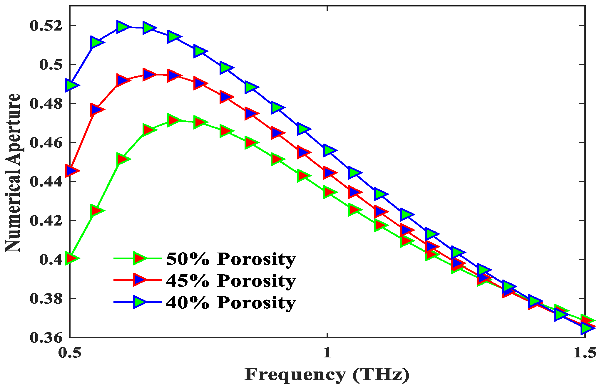
The NA defines the capability of a PCF to accept or emit light. The higher value of NA indicates more light into the core. However, it can be noted that the value of NA more than 0.4 is out of the ordinary for the silica based fibers [18]. In Figure 2, it is nicely visualized that the highest NA of 0.518 is gained for 0.6 THz operating frequency, 40% core porosity and y-polarization mode. This value is immensely comparable with previously reported results [2,18,19]. Thus, the proposed PCF can be highly recommended for medical imaging applications. Figure 2 also shows that the NA is inversely proportional to operating frequency.
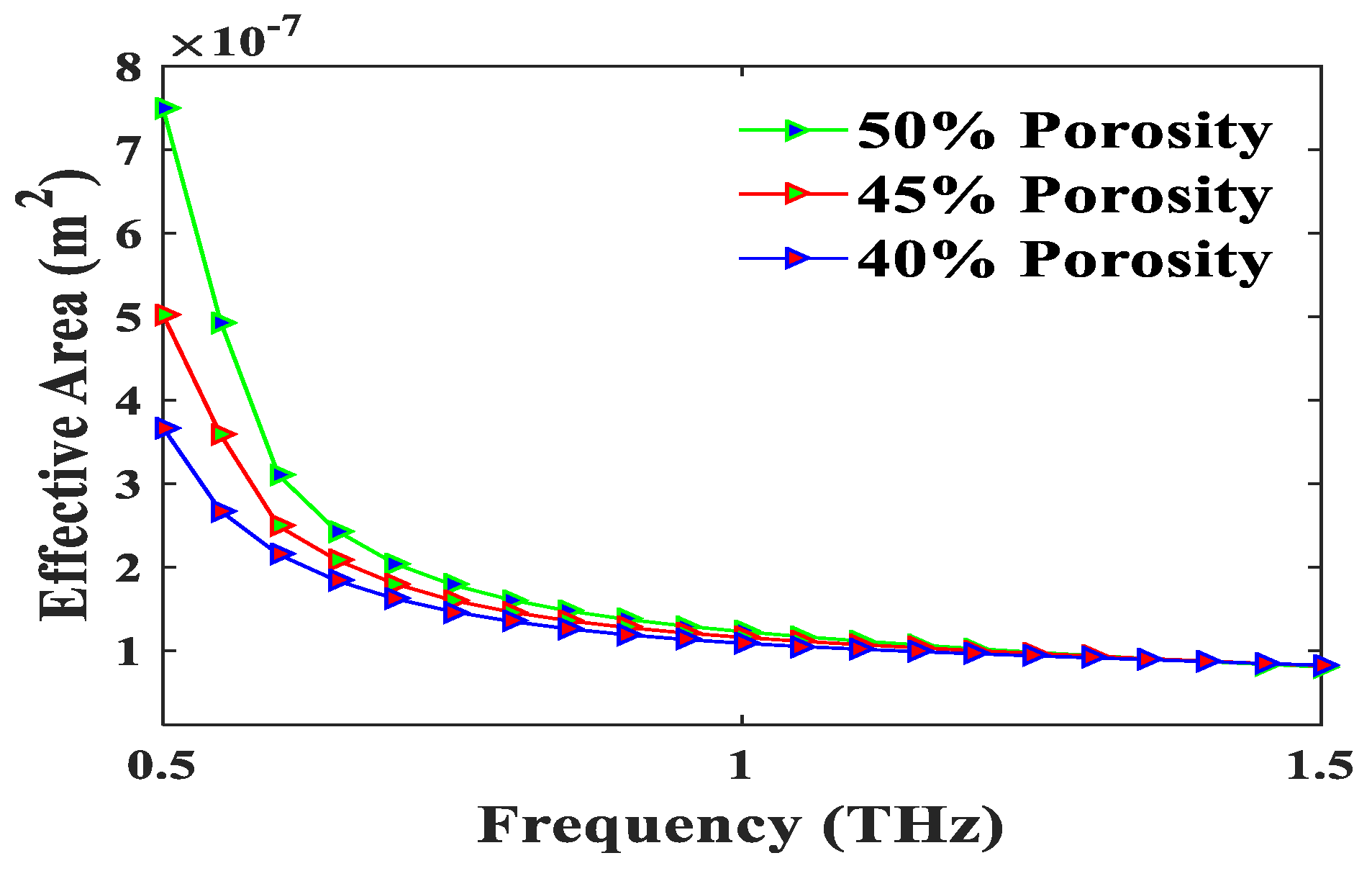
Figure 3 represents the effective area of the proposed PCF for the variation of frequency. Large modal area is indispensable for a fiber for high power transmission or high bit rate communications [4]. The effective area of a fiber defines the capability to transmit data in an optical system or communication area [20]. Figure 3 shows the large modal area of 1.1 × 10 m of the proposed fiber at 1 THz frequency and 40% core porosity. It can be noted that more than 50% power goes into the core and is tightly confined over the whole operating frequencies. Thus, the loss of the proposed fiber will be very low.
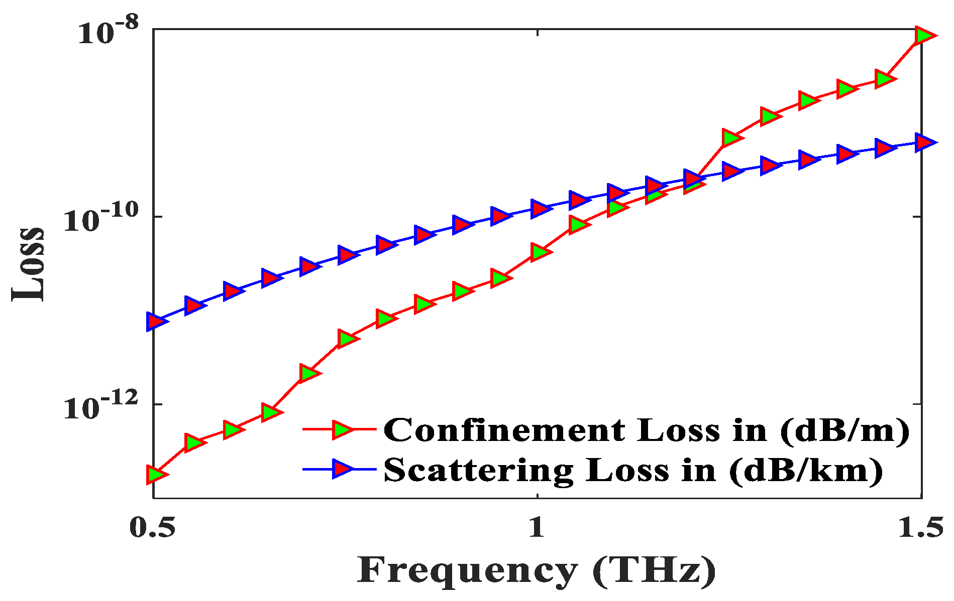
Figure 4 depicts the confinement loss and scattering loss of the proposed fiber for the variation of frequency and 40% porosity. The index contrasts between cladding and core of the proposed fiber are not considerable, which reveals the very low scattering loss. Tightly confinement of light through the core induces negligible confinement loss. The scattering and confinement loss of the proposed fiber are 1.6 × 10 dB/km and 5.42 × 10 dB/cm, respectively, at 0.6 THz frequency and 40% porosity. This value is comparable with previously reported results [2,18]. Now, total loss consisted with scattering loss, confinement loss and EML. EML is the fundamental limiting factor of efficient THz guiding through PCF waveguide.
In Figure 5, the EML of the proposed fiber is exhibited by the variation of frequency. It is gingerly visualized that the EML is proportional with frequency. At optimum design conditions, the EML are 0.051 cm, 0.057 cm and 0.066 cm for 50%, 45% and 40% porosity, respectively, at 0.6 THz frequency. At 50% core porosity, the EML is very low due to the additional power that goes into the core region that is shown in Figure 6. In Figure 6, more than 50% power goes into the core region over the whole operating frequency and creates low fiber loss. The low loss of the proposed fiber makes it suitable in THz radiation propagation.
Figure 7 also demonstrates the behavior of the V-parameter over the frequency range 0.5–1.5 THz. It is also noticed that the value of the V-parameter remains under 2.405 over the whole operating frequency spectrum. V-parameter also exhibits the same characteristics like EML with frequency. Thus, the proposed PCF is a single mode fiber, which promotes the long-distance communication applications. Long distance communication can also be improved by gaining low GVD.
Figure 8 illustrates the GVD as a function of frequency and depicts the very low GVD that enhances the broadband THz transmission over long distances. The proposed PCF shows the near zero flattened dispersion of 0.5 ± 0.6 ps/THz/cm over the 0.8–1.4 THz band. It can be fabricated by using available commercial methods without any impediments because of its design flexibility and structural simplicity.
5. Conclusions
A novel hexahedron core based PCF has been proposed and investigated different guiding properties. Simulated results have revealed low scattering loss, confinement loss and EML of 1.6 × 10 dB/km, 5.42 × 10 dB/cm and 0.066 cm, respectively, for optimum structure. Moreover, the proposed PCF also depicts single modality; the high numerical aperture and core power fraction; near zero flattened dispersion over a broad operating frequency ranges from 0.8 to 1.4 THz. The proposed fiber will be a potential candidate in biomedical imaging, multichannel communication, and sensing applications.
Author Contributions
Conceptualization, B.K.P.; methodology, B.K.P.; software, S.S.; validation, B.K.P. and K.A.; formal analysis, B.K.P.; investigation, K.A.; resources, B.K.P.; data curation, K.A.; writing—original draft preparation, B.K.P.; writing—review and editing, K.A. and M.A.H.; visualization, K.A. and M.A.H.; supervision, K.A.; funding acquisition, M.A.H.
Acknowledgments
M.A.H. would like to acknowledge the financial support. The authors are very grateful to those who participated in this research work.
Conflicts of Interest
This manuscript has not been published yet and is not even under consideration for publication elsewhere. All of the authors have read the manuscript and approved this for submission as well as no competing interests.
References
- Pawar, A.Y.; Sonawane, D.D.; Erande, K.B.; Derle, D.V. Terahertz technology and its applications. Drug Invent. Today 2013, 5, 157–163. [Google Scholar] [CrossRef]
- Sen, S.; Islam, M.S.; Paul, B.K.; Islam, M.I.; Chowdhury, S.; Ahmed, K.; Hasan, M.R.; Uddin, M.S.; Asaduzzaman, S. Ultra-low loss with single mode polymer-based photonic crystal fiber for THz waveguide. J. Opt. Commun. 2017. [Google Scholar] [CrossRef]
- Ahmed, K.; Paul, B.K.; Chowdhury, S.; Sen, S.; Islam, M.I.; Islam, M.S.; Hasan, M.R.; Asaduzzaman, S. Design of a single-mode photonic crystal fibre with ultra-low material loss and large effective mode area in THz regime. IET Optoelectron. 2017, 11, 265–271. [Google Scholar] [CrossRef]
- Ahmed, K.; Chowdhury, S.; Paul, B.K.; Islam, M.S.; Sen, S.; Islam, M.I.; Asaduzzaman, S. Ultrahigh birefringence ultra low material loss porous core single-mode fiber for terahertz wave guidance. Appl. Opt. 2017, 56, 3477–3483. [Google Scholar] [CrossRef] [PubMed]
- Hoo, Y.L.; Jin, W.; Shi, C.; Ho, H.L.; Wang, D.N.; Ruan, S.C. Design and modeling of a photonic crystal fiber gas sensor. Appl. Opt. 2003, 42, 3509–3515. [Google Scholar] [CrossRef] [PubMed]
- Islam, M.S.; Paul, B.K.; Ahmed, K.; Asaduzzaman, S.; Islam, M.I.; Chowdhury, S.; Sen, S.; Bahar, A.N. Liquid-infiltrated photonic crystal fiber for sensing purpose: Design and analysis. Alex. Eng. J. 2018, 57, 1459–1466. [Google Scholar] [CrossRef]
- Osório, J.H.; Hayashi, J.G.; Espinel, Y.A.; Franco, M.A.; Andrés, M.V.; Cordeiro, C.M. Photonic-crystal fiber-based pressure sensor for dual environment monitoring. Appl. Opt. 2014, 53, 668–3672. [Google Scholar] [CrossRef] [PubMed]
- Amiri, I.S.; Paul, B.K.; Ahmed, K.; Aly, A.H.; Zakaria, R.; Yupapin, P.; Vigneswaran, D. Tri-core photonic crystal fiber based refractive index dual sensor for salinity and temperature detection. Microw. Opt. Technol. Lett. 2019, 61, 847–852. [Google Scholar] [CrossRef]
- Hameed, M.F.O.; Obayya, S.S.A.; Wiltshire, R.J. Multiplexer–demultiplexer based on nematic liquid crystal photonic crystal fiber coupler. Opt. Quantum Electron. 2009, 41, 315–326. [Google Scholar] [CrossRef]
- Dadabayev, R.; Shabairou, N.; Zalevsky, Z.; Malka, D. A visible light RGB wavelength demultiplexer based on silicon-nitride multicore PCF. Opt. Laser Technol. 2019, 111, 411–416. [Google Scholar] [CrossRef]
- Malka, D.; Katz, G. An Eight-Channel C-Band Demux Based on Multicore Photonic Crystal Fiber. Nanomaterials 2018, 8, 845. [Google Scholar] [CrossRef] [PubMed]
- Malka, D.; Peled, A. Power splitting of 1 × 16 in multicore photonic crystal fibers. Appl. Surf. Sci. 2017, 417, 34–39. [Google Scholar] [CrossRef]
- Wang, G.; Li, S.; An, G.; Wang, X.; Zhao, Y.; Zhang, W. Design of a polarized filtering photonic-crystal fiber with gold-coated air holes. Appl. Opt. 2015, 54, 8817–8820. [Google Scholar] [CrossRef] [PubMed]
- Islam, R.; Rana, S.; Ahmad, R.; Kaijage, S.F. Bend-insensitive and low-loss porous core spiral terahertz fiber. IEEE Photon. Technol. Lett. 2015, 27, 2242–2245. [Google Scholar] [CrossRef]
- Rana, S.; Hasanuzzaman, G.K.M.; Habib, M.S.; Kaijage, S.F.; Islam, R. Proposal for a low loss porous core octagonal photonic crystal fiber for T-ray wave guiding. Opt. Eng. 2014, 53, 115107. [Google Scholar] [CrossRef]
- Hasan, M.R.; Islam, M.A.; Anower, M.S.; Razzak, S.M.A. Low-loss and bend-insensitive terahertz fiber using a rhombic-shaped core. Appl. Opt. 2016, 55, 8441–8447. [Google Scholar] [CrossRef] [PubMed]
- Hasan, M.R.; Islam, M.A.; Rifat, A.A. A single mode porous-core square lattice photonic crystal fiber for THz wave propagation. J. Eur. Opt. Soc.-Rapid Publ. 2016, 12, 15. [Google Scholar] [CrossRef]
- Sultana, J.; Islam, M.S.; Islam, M.R.; Abbott, D. High numerical aperture, highly birefringent novel photonic crystal fibre for medical imaging applications. Electron. Lett. 2017, 54, 61–62. [Google Scholar] [CrossRef]
- Chowdhury, S.; Sen, S.; Ahmed, K.; Asaduzzaman, S. Design of highly sensible porous shaped photonic crystal fiber with strong confinement field for optical sensing. Opt.-Int. J. Light Electron Opt. 2017, 142, 541–549. [Google Scholar] [CrossRef]
- Ahmed, K.; Islam, M.I.; Paul, B.K.; Islam, M.S.; Sen, S.; Chowdhury, S.; Uddin, M.S.; Asaduzzaman, S.; Bahar, A.N. Effect of photonic crystal fiber background materials in sensing and communication applications. Mater. Discov. 2017, 7, 8–14. [Google Scholar] [CrossRef]
Figure 1.
Schematic view of proposed PCF with modes field for different porosities.

Figure 2.
The numerical aperture as a function of frequency and porosities.

Figure 3.
The effective area of optimum structure as a function of frequency.

Figure 4.
The confinement loss and scattering loss as a function of frequency.

Figure 5.
The effective material loss (EML) as a function of frequency for different porosities.

Figure 6.
The core power fraction as a function of frequency for different porosities.

Figure 7.
The V as a function of frequency for different porosities.

Figure 8.
The dispersion of different porosities as a function of frequency.
© 2019 by the authors. Licensee MDPI, Basel, Switzerland. This article is an open access article distributed under the terms and conditions of the Creative Commons Attribution (CC BY) license (http://creativecommons.org/licenses/by/4.0/).
Share and Cite
MDPI and ACS Style
Kumar Paul, B.; Haque, M.A.; Ahmed, K.; Sen, S. A Novel Hexahedron Photonic Crystal Fiber in Terahertz Propagation: Design and Analysis. Photonics 2019, 6, 32. https://doi.org/10.3390/photonics6010032
AMA Style
Kumar Paul B, Haque MA, Ahmed K, Sen S. A Novel Hexahedron Photonic Crystal Fiber in Terahertz Propagation: Design and Analysis. Photonics. 2019; 6(1):32. https://doi.org/10.3390/photonics6010032
Chicago/Turabian StyleKumar Paul, Bikash, Md. Ashraful Haque, Kawsar Ahmed, and Shuvo Sen. 2019. "A Novel Hexahedron Photonic Crystal Fiber in Terahertz Propagation: Design and Analysis" Photonics 6, no. 1: 32. https://doi.org/10.3390/photonics6010032
Note that from the first issue of 2016, this journal uses article numbers instead of page numbers. See further details here.