Laser 3D Printing of Inorganic Free-Form Micro-Optics

 , , , , and
Abstract
:1. Introduction
2. Materials and Methods
2.1. Used Materials
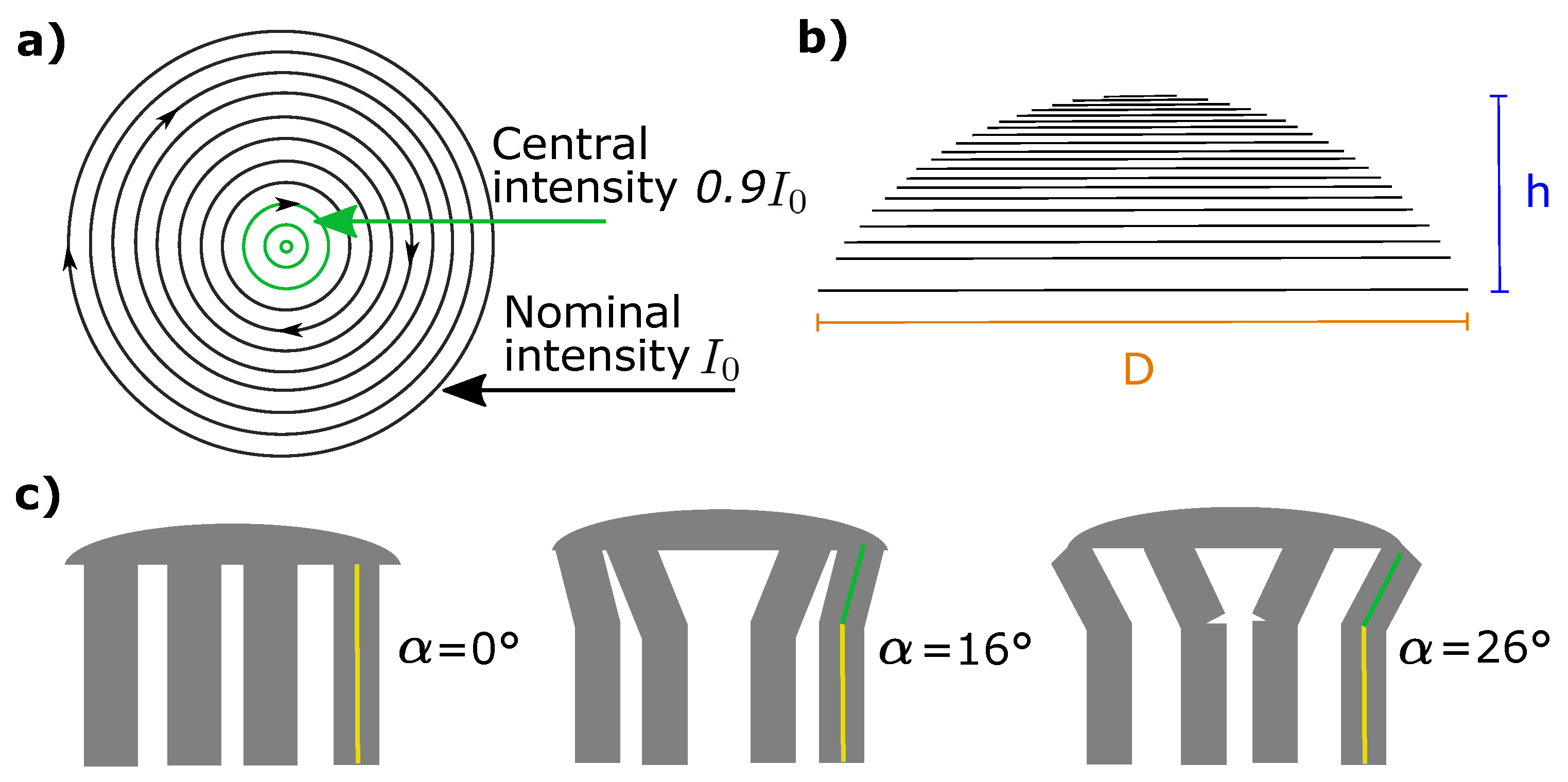
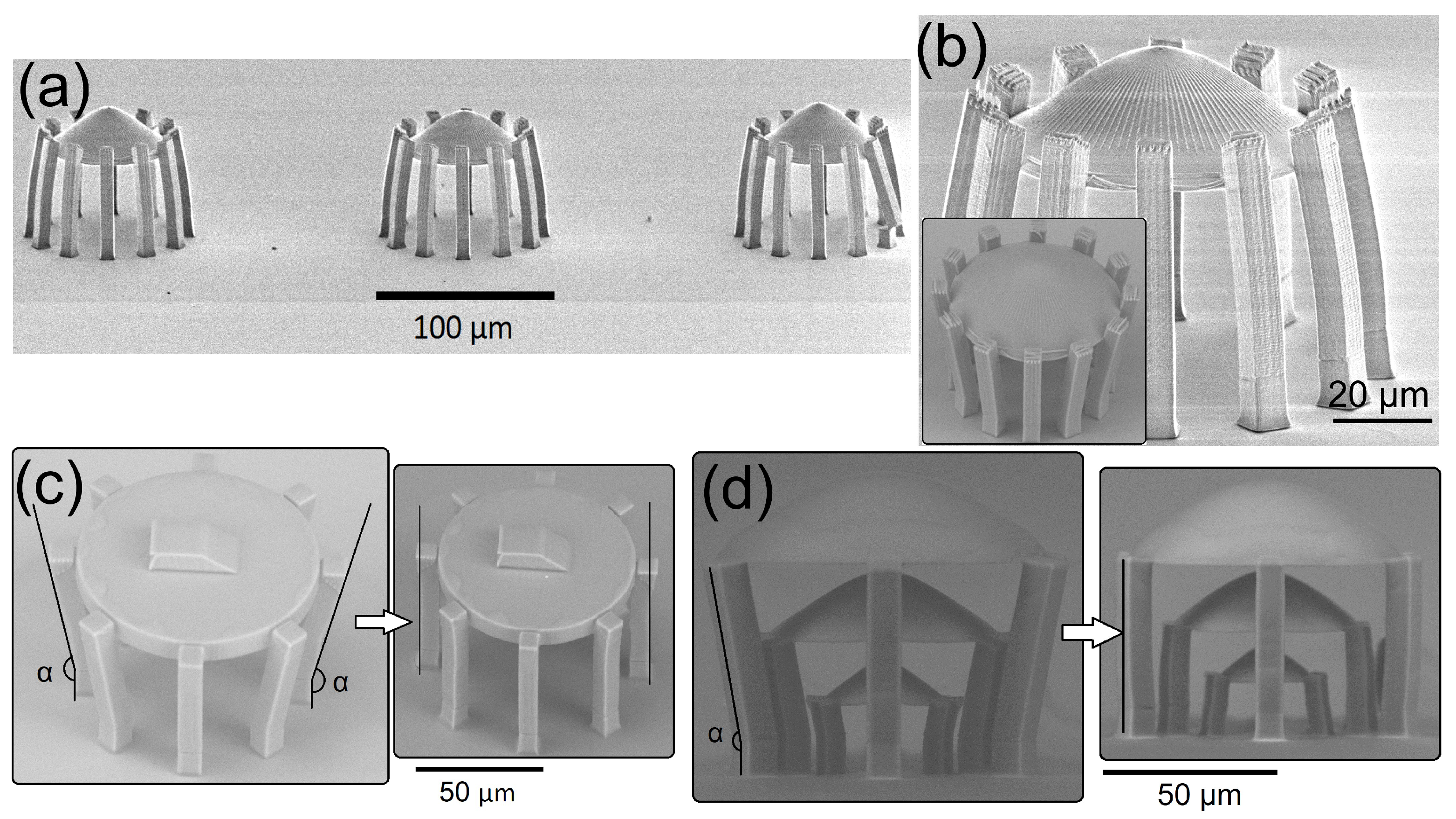
2.2. Geometry
2.3. Employed Equipment
2.4. Calcination
2.5. Optical and Scanning Electron Microscopy Characterization
2.6. Performance Evaluation
3. Results
4. Discussion
4.1. Thermal Effects of the Hybrid Organic-Inorganic Material SZ2080
4.2. Findings in a Wider Context
4.3. Benchmarking Achievements
4.4. Future Research Directions
5. Conclusions
- Laser multi-photon 3D nanolithography of hybrid materials in combination with high-temperature calcination is enabling (nano-)additive manufacturing of free-form micro-optics out of transparent and pure inorganic glasses without any fissure of crucial geometrical distortions.
- The proposed method offers advantage of uniforming the material in respect to the laser lithography 3D structuring and developing process, thus making the n insensitive to the specific exposure conditions by improving its internal homogeneity and surface quality [39].
- The future work will be targeted for improving the element itself by additionally pre-compensating for the lens shape (it can be made concave initially to balance the volume of the material), optimizing the calcination treatments (taking into account the specific elevation/cooling steps), and modifying the pristine material (some different Si:Zr ratios as well as validating other inorganic ingredients).
- Finally, the developed methodology is offers the production of highly resilient 3D micro-optical components for harsh chemical, mechanical, pressure and temperature variation environments, including a high optical damage threshold.
Author Contributions
Funding
Data Availability Statement
Acknowledgments
Conflicts of Interest
References
- Malinauskas, M.; Žukauskas, A.; Hasegawa, S.; Hayasaki, Y.; Mizeikis, V.; Buividas, R.; Juodkazis, S. Ultrafast laser processing of materials: From science to industry. Light Sci. Appl. 2016, 5, e16133. [Google Scholar] [CrossRef] [PubMed] [Green Version]
- Thiele, S.; Arzenbacher, K.; Gissibl, T.; Giessen, H.; Herkommer, A.M. 3D-printed eagle eye: Compound microlens system for foveated imaging. Sci. Adv. 2017, 3, 1602655. [Google Scholar] [CrossRef] [PubMed] [Green Version]
- Eaton, S.M.; Hadden, J.P.; Bharadwaj, V.; Forneris, J.; Picollo, F.; Bosia, F.; Sotillo, B.; Giakoumaki, A.N.; Jedrkiewicz, O.; Chiappini, A.; et al. Quantum Micro–Nano Devices Fabricated in Diamond by Femtosecond Laser and Ion Irradiation. Adv. Quant. Technol. 2019, 2, 1900006. [Google Scholar] [CrossRef] [Green Version]
- Merkininkaite, G.; Aleksandravicius, E.; Malinauskas, M.; Gailevicius, D.; Sakirzanovas, S. Laser Additive Manufacturing of Si/ZrO2 Tunable Crystalline Phase 3D Nanostructures. Opto-Electr. Adv. 2022, 5, 210077. [Google Scholar] [CrossRef]
- Skliutas, E.; Lebedevaite, M.; Kabouraki, E.; Baldacchini, T.; Ostrauskaite, J.; Vamvakaki, M.; Farsari, M.; Juodkazis, S.; Malinauskas, M. Polymerization mechanisms initiated by spatio-temporally confined light. Nanophotonics 2021, 10, 1211–1242. [Google Scholar] [CrossRef]
- Bouzin, M.; Zeynali, A.; Marini, M.; Sironi, L.; Scodellaro, R.; D’Alfonso, L.; Collini, M.; Chirico, G. Multiphoton Laser Fabrication of Hybrid Photo-Activable Biomaterials. Sensors 2021, 21, 5891. [Google Scholar] [CrossRef] [PubMed]
- Yang, L.; Mayer, F.; Bunz, U.H.F.; Blasco, E.; Wegener, M. Multi-material multi-photon 3D laser micro- and nanoprinting. Light Adv. Manuf. 2021, 2, 1–17. [Google Scholar] [CrossRef]
- Gailevičius, D.; Padolskytė, V.; Mikoliūnaitė, L.; Šakirzanovas, S.; Juodkazis, S.; Malinauskas, M. Additive-manufacturing of 3D glass-ceramics down to nanoscale resolution. Nanoscale Horiz. 2019, 4, 647–651. [Google Scholar] [CrossRef]
- Bertoncini, A.; Liberale, C. Polarization Micro-Optics: Circular Polarization From a Fresnel Rhomb 3D Printed on an Optical Fiber. Photon. Technol. Lett. 2018, 30, 1882–1885. [Google Scholar] [CrossRef]
- Hou, Z.S.; Xiong, X.; Cao, J.J.; Chen, Q.D.; Tian, Z.N.; Ren, X.F.; Sun, H.B. On-Chip Polarization Rotators. Adv. Opt. Mater. 2019, 7, 1900129. [Google Scholar] [CrossRef]
- Bertoncini, A.; Liberale, C. 3D printed waveguides based on photonic crystal fiber designs for complex fiber-end photonic devices. Optica 2020, 7, 1487–1494. [Google Scholar] [CrossRef]
- Schmid, M.; Sterl, F.; Thiele, S.; Herkommer, A.; Giessen, H. 3D printed hybrid refractive/diffractive achromat and apochromat for the visible wavelength range. Opt. Lett. 2021, 46, 2485–2488. [Google Scholar] [CrossRef]
- Varapnickas, S.; Chandran Thodika, S.; Moroté, F.; Juodkazis, S.; Malinauskas, M.; Brasselet, E. Birefringent optical retarders from laser 3D-printed dielectric metasurfaces. Appl. Phys. Lett. 2021, 118, 151104. [Google Scholar] [CrossRef]
- Hong, Z.; Ye, P.; Loy, D.A.; Liang, R. Three-dimensional printing of glass micro-optics. Optica 2021, 8, 904–910. [Google Scholar] [CrossRef]
- Kotz, F.; Quick, A.S.; Risch, P.; Martin, T.; Hoose, T.; Thiel, M.; Helmer, D.; Rapp, B.E. Two-Photon Polymerization of Nanocomposites for the Fabrication of Transparent Fused Silica Glass Microstructures. Adv. Mater. 2021, 33, 2006341. [Google Scholar] [CrossRef]
- Doualle, T.; André, J.C.; Gallais, L. 3D printing of silica glass through a multiphoton polymerization process. Opt. Lett. 2021, 46, 364–367. [Google Scholar] [CrossRef]
- Vyatskikh, A.; Ng, R.C.; Edwards, B.; Briggs, R.M.; Greer, J.R. Additive Manufacturing of High-Refractive-Index, Nanoarchitected Titanium Dioxide for 3D Dielectric Photonic Crystals. Nano Lett. 2020, 20, 3513–3520. [Google Scholar] [CrossRef]
- Jonušauskas, L.; Gailevičius, D.; Mikoliūnaitė, L.; Sakalauskas, D.; Šakirzanovas, S.; Juodkazis, S.; Malinauskas, M. Optically Clear and Resilient Free-Form µ-Optics 3D-Printed via Ultrafast Laser Lithography. Materials 2017, 10, 12. [Google Scholar] [CrossRef] [PubMed]
- Butkutė, A.; Čekanavičius, L.; Rimšelis, G.; Gailevičius, D.; Mizeikis, V.; Melninkaitis, A.; Baldacchini, T.; Jonušauskas, L.; Malinauskas, M. Optical damage thresholds of microstructures made by laser three-dimensional nanolithography. Opt. Lett. 2020, 45, 13–16. [Google Scholar] [CrossRef]
- Kabouraki, E.; Melissinaki, V.; Yadav, A.; Melninkaitis, A.; Tourlouki, K.; Tachtsidis, T.; Kehagias, N.; Barmparis, G.D.; Papazoglou, D.G.; Rafailov, E.; et al. High laser induced damage threshold photoresists for nano-imprint and 3D multi-photon lithography. Nanophotonics 2021, 10, 3759–3768. [Google Scholar] [CrossRef]
- Bundy, K.; Westfall, K.; MacDonald, N.; Kupke, R.; Savage, M.; Poppett, C.; Alabi, A.; Becker, G.; Burchett, J.; Capak, P.; et al. FOBOS: A Next-Generation Spectroscopic Facility. BAAS 2019, 51, 7. [Google Scholar]
- Smith, D.; Ng, S.; Han, M.; Katkus, T.; Anand, V.; Glazebrook, K.; Juodkazis, S. Imaging with diffractive axicons rapidly milled on sapphire by femtosecond laser ablation. Appl. Phys. B 2021, 127, 154. [Google Scholar] [CrossRef]
- Ovsianikov, A.; Viertl, J.; Chichkov, B.; Oubaha, M.; MacCraith, B.; Sakellari, I.; Giakoumaki, A.; Gray, D.; Vamvakaki, M.; Farsari, M.; et al. Ultra-Low Shrinkage Hybrid Photosensitive Material for Two-Photon Polymerization Microfabrication. ACS Nano 2008, 2, 2257–2262. [Google Scholar] [CrossRef]
- Jonušauskas, L.; Gailevičius, D.; Rekštytė, S.; Baldacchini, T.; Juodkazis, S.; Malinauskas, M. Mesoscale laser 3D printing. Opt. Express 2019, 27, 15205–15221. [Google Scholar] [CrossRef] [Green Version]
- Sharipova, M.I.; Baluyan, T.G.; Abrashitova, K.A.; Kulagin, G.E.; Petrov, A.K.; Chizhov, A.S.; Shatalova, T.B.; Chubich, D.; Kolymagin, D.A.; Vitukhnovsky, A.G.; et al. Effect of pyrolysis on microstructures made of various photoresists by two-photon polymerization: Comparative study. Opt. Mater. Express 2021, 11, 371–384. [Google Scholar] [CrossRef]
- Ristok, S.; Thiele, S.; Toulouse, A.; Herkommer, A.M.; Giessen, H. Stitching-free 3D printing of millimeter-sized highly transparent spherical and aspherical optical components. Opt. Mater. Express 2020, 10, 2370–2378. [Google Scholar] [CrossRef]
- Schneider, C.A.; Rasband, W.S.; Eliceiri, K.W. NIH Image to ImageJ: 25 years of image analysis. Nat. Methods 2012, 9, 671–675. [Google Scholar] [CrossRef]
- Nogami, M. Glass preparation of the ZrO2-SiO2 system by the sol-gel process from metal alkoxides. J. Non-Crystall. Sol. 1985, 69, 415–423. [Google Scholar] [CrossRef]
- Žukauskas, A.; Matulaitienė, I.; Paipulas, D.; Niaura, G.; Malinauskas, M.; Gadonas, R. Tuning the refractive index in 3D direct laser writing lithography: Towards GRIN microoptics. Laser Photon. Rev. 2015, 9, 706–712. [Google Scholar] [CrossRef]
- Porte, X.; Dinc, N.U.; Moughames, J.; Panusa, G.; Juliano, C.; Kadic, M.; Moser, C.; Brunner, D.; Psaltis, D. Direct (3+1)D laser writing of graded-index optical elements. Optica 2021, 8, 1281–1287. [Google Scholar] [CrossRef]
- Bauer, J.; Izard, A.G.; Zhang, Y.; Baldacchini, T.; Valdevit, L. Thermal post-curing as an efficient strategy to eliminate process parameter sensitivity in the mechanical properties of two-photon polymerized materials. Opt. Express 2020, 28, 20362–20371. [Google Scholar] [CrossRef]
- Žukauskas, A.; Batavičiūtė, G.; Ščiuka, M.; Balevičius, Z.; Melninkaitis, A.; Malinauskas, M. Effect of the photoinitiator presence and exposure conditions on laser-induced damage threshold of ORMOSIL (SZ2080). Opt. Mater. 2015, 39, 224–231. [Google Scholar] [CrossRef]
- Skliutas, E.; Lebedevaite, M.; Kasetaite, S.; Lileikis, S.; Ostrauskaite, J.; Malinauskas, M. A Bio-Based Resin for a Multi-Scale Optical 3D Printing. Sci. Rep. 2020, 10, 9758. [Google Scholar] [CrossRef]
- Amico, C.D.; Martin, G.; Troles, J.; Cheng, G.; Stoian, R. Multiscale Laser Written Photonic Structures in Bulk Chalcogenide Glasses for Infrared Light Transport and Extraction. Photonics 2021, 8, 211. [Google Scholar]
- Wallin, T.; Pikul, J.; Shepherd, R. 3D printing of soft robotic systems. Nat. Rev. Mater. 2018, 3, 84–100. [Google Scholar] [CrossRef]
- Han, D.D.; Zhang, Y.L.; Ma, J.N.; Liu, Y.Q.; Han, B.; Sun, H.B. Light-Mediated Manufacture and Manipulation of Actuators. Adv. Mater. 2016, 28, 8328–8343. [Google Scholar] [CrossRef]
- You, R.; Liu, Y.Q.; Hao, Y.L.; Han, D.D.; Zhang, Y.L.; You, Z. Laser Fabrication of Graphene-Based Flexible Electronics. Adv. Mater. 2019, 32, 1901981. [Google Scholar] [CrossRef]
- Liu, Y.Q.; Mao, J.W.; Chen, Z.D.; Han, D.D.; Jiao, Z.Z.; Ma, J.N.; Jiang, H.B.; Yang, H. Three-dimensional micropatterning of graphene by femtosecond laser direct writing technology. Opt. Lett. 2020, 45, 113–116. [Google Scholar] [CrossRef]
- Schmid, M.; Ludescher, D.; Giessen, H. Optical properties of photoresists for femtosecond 3D printing: Refractive index, extinction, luminescence-dose dependence, aging, heat treatment and comparison between 1-photon and 2-photon exposure. Opt. Mater. Express 2019, 9, 4564–4577. [Google Scholar] [CrossRef]
- Tičkūnas, T.; Perrenoud, M.; Butkus, S.; Gadonas, R.; Rekštytė, S.; Malinauskas, M.; Paipulas, D.; Bellouard, Y.; Sirutkaitis, V. Combination of additive and subtractive laser 3D microprocessing in hybrid glass/polymer microsystems for chemical sensing applications. Opt. Express 2017, 25, 26280–26288. [Google Scholar] [CrossRef] [PubMed]
- Wang, C.; Yang, L.; Zhang, C.; Rao, S.; Wang, Y.; Wu, S.; Li, J.; Hu, Y.; Wu, D.; Chu, J.; et al. Multilayered skyscraper microchips fabricated by hybrid “all-in-one” femtosecond laser processing. Microsyst. Nanoeng. 2019, 5, 17. [Google Scholar] [CrossRef] [Green Version]
- Martinod, M.A.; Norris, B.; Tuthill, P.; Lagadec, T.; Jovanovic, N.; Cvetojevic, N.; Gross, S.; Arriola, A.; Gretzinger, T.; Withford, M.J.; et al. Scalable photonic-based nulling interferometry with the dispersed multi-baseline GLINT instrument. Nat. Commun. 2021, 12, 2465. [Google Scholar] [CrossRef]
- Wen, X.; Zhang, B.; Wang, W.; Ye, F.; Yue, S.; Guo, H.; Gao, G.; Zhao, Y.; Fang, Q.; Nguyen, C.; et al. 3D-printed silica with nanoscale resolution. Nat. Mater. 2021, 20, 1506–1511. [Google Scholar] [CrossRef]


| Micro-Structure | Before | After | Shrinkage | Focal Distance |
|---|---|---|---|---|
| Supports at 0 ° | 49.3 μm | 28.6 μm | 42% | 40.4 μm |
| Supports at 16 ° | 49.0 μm | 28.8 μm | 41.3% | 38.0 μm |
| Supports at 26 ° | 48.5 μm | 28.5 μm | 41.3% | 37.7 μm |
| Average | 48.9 ± 0.5 μm | 28.6 ± 0.5 μm | 42.7 ± 1.5% | 38.7 ± 1.7 μm |
Publisher’s Note: MDPI stays neutral with regard to jurisdictional claims in published maps and institutional affiliations. |
© 2021 by the authors. Licensee MDPI, Basel, Switzerland. This article is an open access article distributed under the terms and conditions of the Creative Commons Attribution (CC BY) license (https://creativecommons.org/licenses/by/4.0/).
Share and Cite
Gonzalez-Hernandez, D.; Varapnickas, S.; Merkininkaitė, G.; Čiburys, A.; Gailevičius, D.; Šakirzanovas, S.; Juodkazis, S.; Malinauskas, M. Laser 3D Printing of Inorganic Free-Form Micro-Optics. Photonics 2021, 8, 577. https://doi.org/10.3390/photonics8120577
Gonzalez-Hernandez D, Varapnickas S, Merkininkaitė G, Čiburys A, Gailevičius D, Šakirzanovas S, Juodkazis S, Malinauskas M. Laser 3D Printing of Inorganic Free-Form Micro-Optics. Photonics. 2021; 8(12):577. https://doi.org/10.3390/photonics8120577
Chicago/Turabian StyleGonzalez-Hernandez, Diana, Simonas Varapnickas, Greta Merkininkaitė, Arūnas Čiburys, Darius Gailevičius, Simas Šakirzanovas, Saulius Juodkazis, and Mangirdas Malinauskas. 2021. "Laser 3D Printing of Inorganic Free-Form Micro-Optics" Photonics 8, no. 12: 577. https://doi.org/10.3390/photonics8120577