Performance of Helical Ribbon and Screw Impellers for Mixing Viscous Fluids in Cylindrical Reactors

1
Institute of Science and Technology, University Center Ahmed Salhi of Naâma (Ctr Univ Naâma), P.O. 66, Naâma 45000, Algeria
2
Faculty of Technology, University Hassiba Ben Bouali, Chlef 02000, Algeria
3
Department of Technical Sciences, University Amar Thilidji, Laghouat 03000, Algeria
*
Author to whom correspondence should be addressed.
ChemEngineering 2018, 2(2), 26; https://doi.org/10.3390/chemengineering2020026
Submission received: 21 March 2018
/
Revised: 9 May 2018
/
Accepted: 3 June 2018
/
Published: 11 June 2018
Abstract
:The present paper deals with the mixing of a highly viscous fluid by close-clearance impellers in cylindrical vessels. The study is performed via numerical simulations. Calculations are achieved by the discretization of continuity and momentum equations with the finite volume method. The effect of blade diameter and its shape on the well-stirred region size and the power consumption is investigated. For highly viscous fluids, the obtained results suggest the use of impellers rotating at low Reynolds number, and having a blade with the same shape of the tank to ensure mixing near the vessel base. A comparison is made between the performance of a simple helical ribbon (HR), a simple small screw (SS), helical ribbon-small screw (HR-SS) and a large screw (LS) impeller. The predicted results allow the following classification of impellers studied, based on less power requirements and small size of well-agitated region: SS < HR < HR-SS < LS.
1. Introduction
Mixing of highly viscous fluids is widely used in many industrial processes, e.g., for the production of foods, polymers or paints. Obtaining an efficient mixing with high quality of homogenization at low impeller rotational speeds is a challenging task, due the high power consumption required for moving the viscous fluid.
Among the several stirrers available in industries, the helical ribbon and screw impellers are efficient for the mixing of highly viscous liquids. These impellers are often operated in the laminar regime of fluid flows. Depending on the purpose of the mixing operation, the helical ribbon impeller may be used with one or more helical ribbons mounted on a central shaft, supported or not by cross-beams [1,2].
In a stirred tank fermenter, Mohd et al. [3] compared the performance of a Rushton turbine and a double-flight helical ribbon impeller (HRI). They reported that the HRI operating at moderate conditions (250 rpm) performs better and requires less energy than a double Rushton turbine operating at an optimum condition (600 rpm). Yao et al. [4] and Ameur [5] studied numerically the total and local dispersive mixing performance of double helical ribbons (DHR) and Maxblend impellers. Their results showed that the DHR can achieve a good total circulation throughout the agitated vessel, but it can’t give a promising local mixing performance.
Via numerical simulations and using the smoothed particle hydrodynamics (SPH) method, Robinson and Cleary [6] explored the mixing performance of helical ribbon impellers with a Newtonian fluid. They reported that the addition of an extra ribbon to the single helical ribbon (SHR) doubles the number of smaller circulation cells of fluid; thereby improving the overall mixing rate.
Delaplace et al. [7] proposed an approximate analytical model to predict the power required for stirring shear-thinning fluids with helical ribbon impellers at low Reynolds numbers. Zhang et al. [8] simulated the 3D non-Newtonian flows generated by a double helical ribbon (DHR) agitator and they used three CFD (Computational Fluid Dynamics) methods to calculate the Metzner constant. Ameur et al. [9,10] studied the effect of blade pitch and other operating conditions on the flow patterns and power consumption with helical screw impellers. Maingonnat et al. [11] studied the link between the power consumption, operating conditions and the rheological behavior of fluids stirred by a double ribbon impeller (Ekato-Paravisc). Driss et al. [12] simulated the Newtonian laminar flows in vessels stirred by double helical ribbons (DHR) and double helical screws (DHS) impellers. Their results revealed that the double helical ribbons impeller yields more active velocity field and pumping flow. Also, the energy efficiency reaches the highest values at the same Reynolds number with DHR impeller.
Ameur et al. [13] compared, via numerical simulations, the performance of a Simple Helical Ribbon (SHR) and Double Helical Ribbon (DHR) impellers for mixing shear thinning fluids. They found that the DHR impeller enhances the fluid circulation but an additional power is consumed.
Anne-Archard et al. [14] discussed the distributions of shear rates and their link to power consumed when mixing power-law fluids with helical and anchor impellers. They established a Metzner–Otto correlation for mixing in power-law fluids (Bingham, Herschel-Bulkley and Casson fluids). The comparison made by Iranshahi et al. [15] between the anchor, DHR and EkatoParavisc impellers in term of mixing characteristics revealed that the DHR is more efficient than the EkatoParavisc. The simulation results given by Yu et al. [11] suggest a great potential for using the helical ribbon impeller for the mixing of high solids digester. Dieulot et al. [16] used a non standard helical ribbon agitator fitted with an anchor at the bottom in unsteady agitation conditions. They found that energy savings can reach up to 60% compared to the energy required to obtain the same mixing time with a constant agitation speed.
Kuncewicz et al. [17] used a two-dimensional numerical model describing the Newtonian laminar fluid flows with a screw impeller. They proposed an optimization criterion of the tank-impeller system regarding mixing time. Masiuk and Rakoczy [18] modeled the mixing of granular materials by a multi ribbon blender. They showed in their study that the theory of information can be employed to describe the random process of mixing of granular materials by this kind of impellers. Rivera et al. [19] mounted a Maxblend impeller and a double helical ribbon agitator on two independent coaxial shafts rotating at different speeds, for obtaining the so called Super blend coaxial stirrer. This mixer configuration is found as a good alternative for tough mixing applications.
Practical designs of mixers are generally performed based on experiments and measurements, which are often expensive and not an easy task [20,21,22]. However, CFD (Computational Fluid Dynamics) simulations may be an efficient alternative. The analysis of mixing characteristics may be achieved in less time and with a greater flexibility in visualizing the fluid motions in the whole vessel volume [23].
The present paper investigates via numerical simulations the mixing characteristics of this class of industrial stirrers. We focus on the effect of impeller geometry on the flow fields and power consumption. Effects of the blade width of a helical ribbon are explored. Also, a comparison between the performance of a Helical Ribbon (HR), a Small Screw (SS), a Large Screw (LS) and a Helical Ribbon-Small Screw (HR-SS) is made.
As stated above, some papers have been published on the performance of double helical ribbon (DHR) and double helical screw (DHS) impellers. However, in this paper, we compare the efficiency of HR and HS impellers used alone and in combination.
2. Geometry of the Mixing System
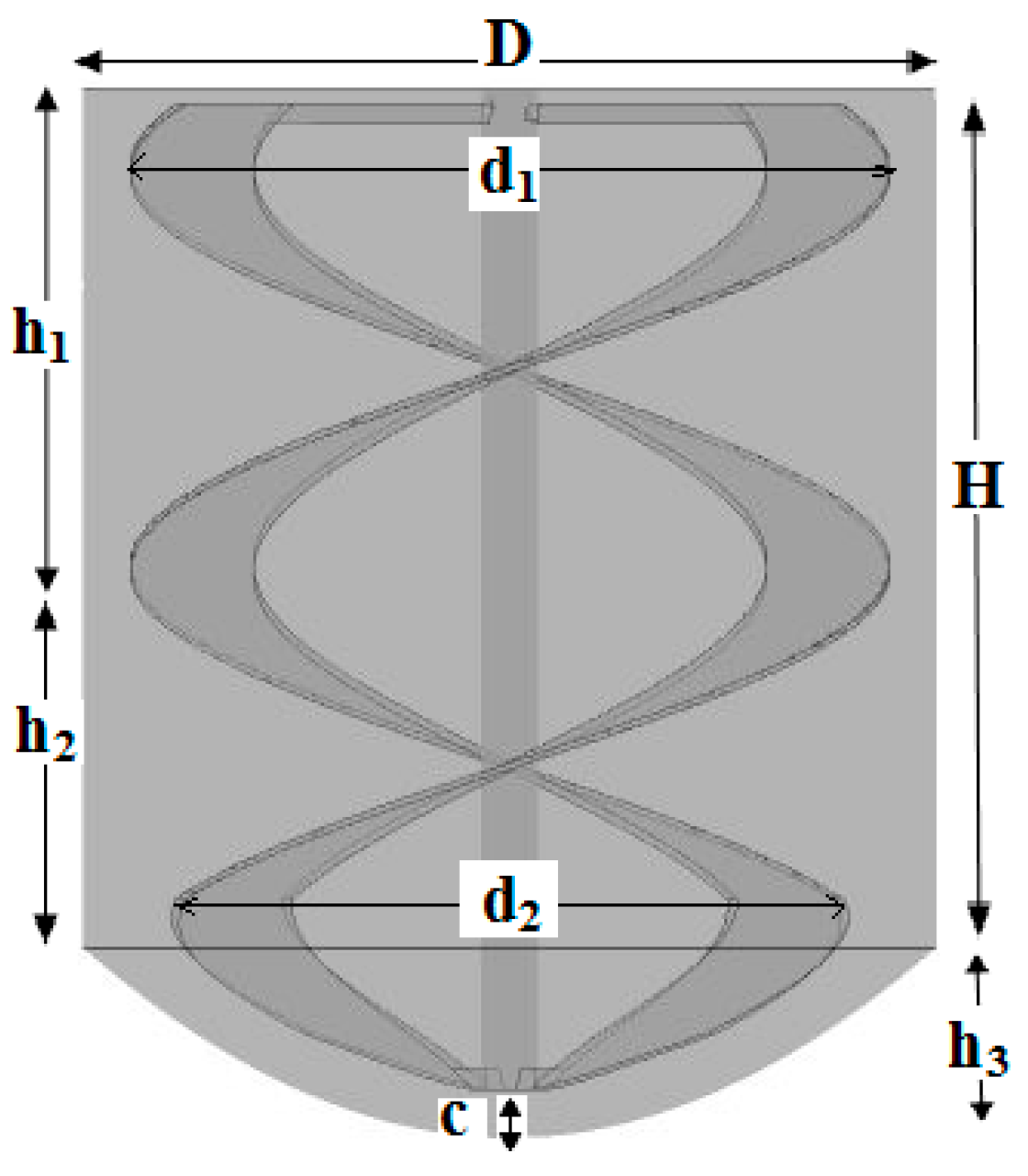
The base structure of the stirrer is a cylindrical unbaffled vessel with a diameter D = 300 mm. The agitation of fluid is ensured by a rotating helical ribbon stirrer (Figure 1). In this paper, effects of the impeller blade width are investigated by realizing three geometrical configurations, namely Case 1 to 3 (details are summarized in Table 1).
Two other geometrical configurations are performed in order to explore the effects of the vessel base design, namely Case 4 and 5 (details are available in Table 2).
3. Materials and Methods
3.1. Variable Definition
Malt syrup solution is used as a working medium which is a typical Newtonian fluid. The Malt syrup is colorless, transparent, tasteless and nontoxic. The viscosity changes with concentration, for a concentration of 71% it has the dynamic viscosity η = 0.8 Pa.S and the density ρ = 1338 kg/m3. We note that these fluid properties are determined experimentally by Liu et al. [24].
The continuity equation for incompressible fluids is given by the following equation:
Navier-Stokes equations are written in a rotating frame reference. So, the centrifugal and the Coriolis accelerations terms are added. These equations, written in cylindrical coordinates (r, θ, z), are expressed in the general conservation form as follows:
For a Newtonian fluid, the Reynolds number is given by the following equation:
where N is the stirring rate in RPM (rounds per minute) and d2 in the impeller diameter. In dimensionless form, we define the power number as:
where P is the power consumption calculated as:
where Qv is the viscous dissipation and v is the vessel volume. We define also the radial and axial coordinates and velocity in dimensionless form, respectively, as:
where D is the vessel diameter, R is the radial coordinate and Z is the axial coordinate.
R* = 2R/D; R* = Z/D; V* = V/πNd2
3.2. Numerical Simulation
Simulations were performed by using the CFD code CFX 17.0 (Ansys Inc., Canonsburg, PA, USA). For modeling fluid flows in unbaffled vessels, the Rotating Reference Frame (RRF) approach is used, i.e., the stirrer is kept stationary and the outer wall of the tank is given an angular velocity equal in magnitude and opposite in direction to the velocity of the rotating frame. The RRF method has been used for several applications in unbaffled stirred tank reactors [15,25] and satisfactory results have been obtained.
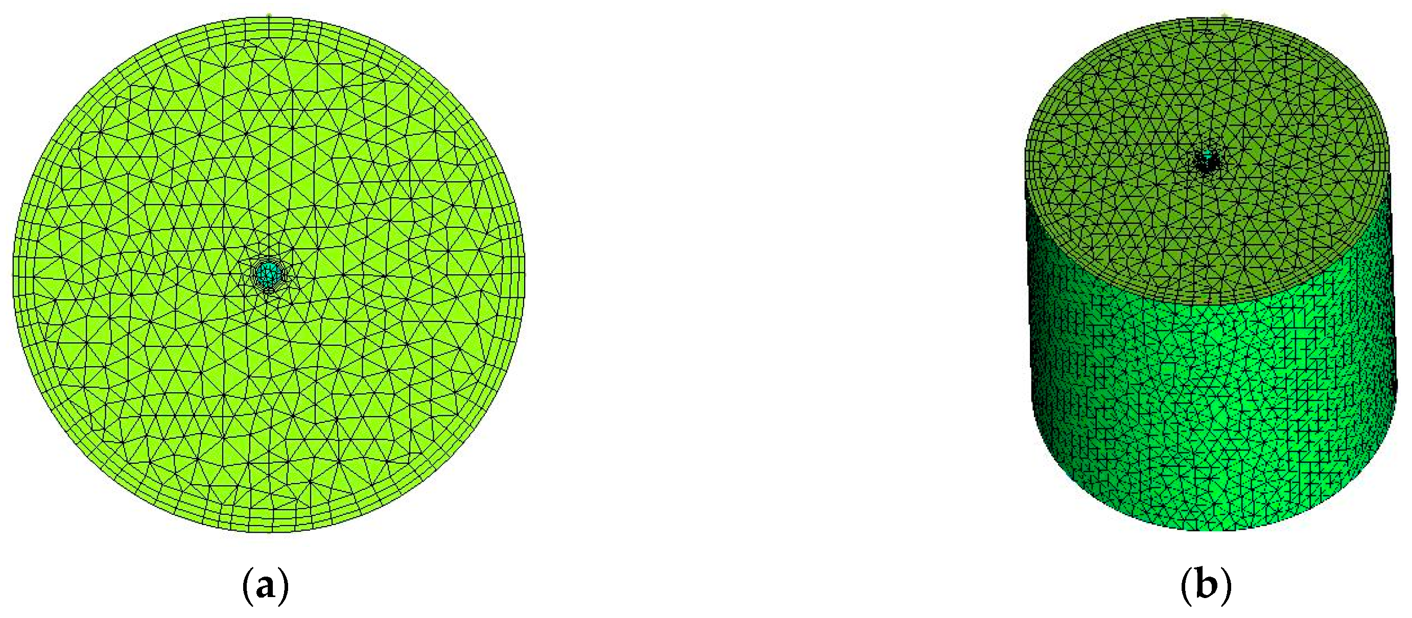
In the laminar and stationary regime and for an incompressible fluid, the momentum equations (i.e., Navier-Stokes equations) were solved by using the finite volume method. The first step is the generation of grids, i.e., dividing the calculation domain into small control volumes. A pre processor (ICEM CFD 17.0, Ansys Inc) was used to create the geometry of the mixing system and to discretise the flow domain into tetrahedral cells (Figure 2). The density of cells needs to be fine enough to capture the flow details, but not so fine, since problems described by large numbers of cells require more time to be solved. After achieving mesh tests, the total number of elements was about 1.2 million. Solutions were considered to be converged when the residual targets of velocities and pressure drop below 10−6. For this value of residual targets, the computational time was about 2–3 h with a computer machine having a 2.20 GHz Pentium(R) i7 Core CPU with 8.0 GB of RAM. Further details can be found in our previous paper [26].
4. Validation of the Predicted Results
As a first step, we have seen necessary to check the reliability of the computer code and the correctness of the numerical method performed. To this end, we refer to the experimental work of Liu et al. [24]. For the same geometry and operating conditions, the variation of power number vs. Reynolds number is given in Figure 3. The comparison between our predicted results and the experimental data of Liu and his co-authors shows a satisfactory agreement.
5. Results and Discussion
5.1. Effect of the Blade Width
This section describes the fluid flows around the stirrer and investigates its mixing characteristics.
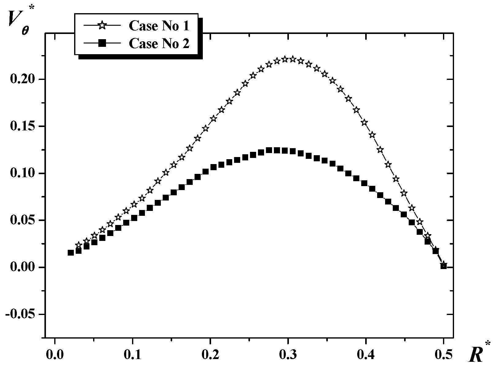
The flow generated by the helical ribbon impeller is tangential; this is why we focus here on the variation of the tangential velocity along the vessel radius (Figure 4). The tangential velocity is presented on a line located at a vertical position Z* = Z/D = 0.45 and an angular position θ = 90°. We note the plane passing through the blade tip represents θ = 0°. For any case studied, the tangential velocity increases continually from the impeller shaft until the blade tip, where the maximum value is reached. Then, it (Vθ*) decreases again until becoming negligible at the tank wall. For this angular position (i.e., θ = 90°), the tangential velocity increases with the increase of the blade diameter.
For highly viscous fluids, the agitation is usually done with a low-speed rotary mixer. While the impeller is rotating at low speeds and the fluid flow is laminar, the mixing is ensured by chaotic folding and stretching actions on the fluid, which is necessary in any agitation process that does not based on diffusion [27].
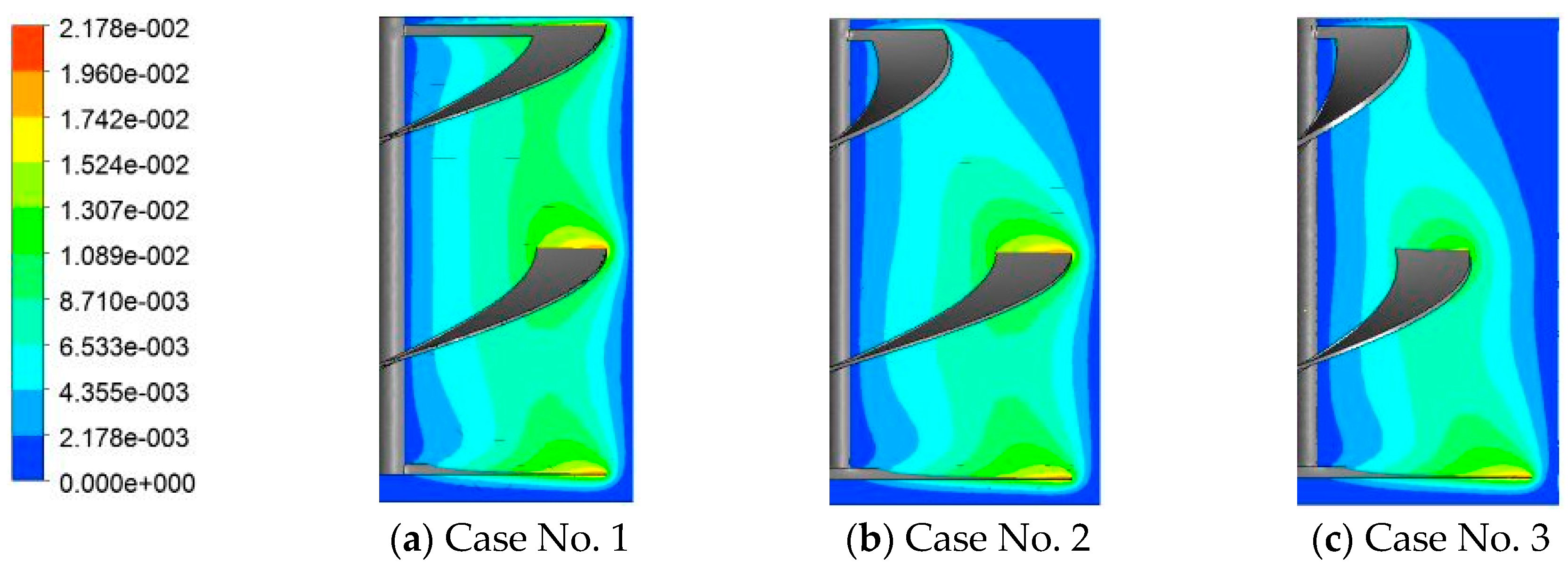
If the diameter of the blade is small, it is likely to have less stirred areas near the vessel wall (Figure 5c). Hence the necessity of design of close-clearance impellers with a blade which reaches the vessel walls (Figure 5a). Increasing the diameter of the blade increases the good mixing zone, but with an additional energy cost (Table 3).
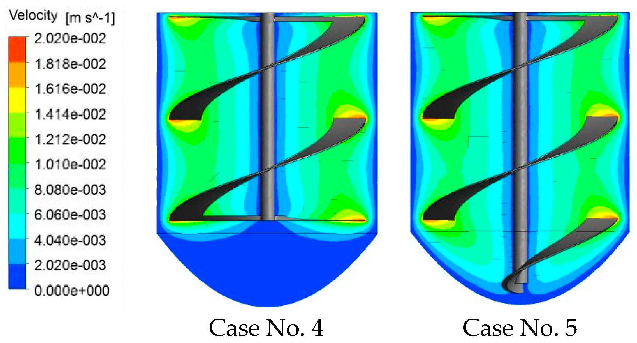
5.2. Effect of the Bottom Shape
In the same context as the previous section, we show here the influence of the blade shape. As illustrated in Figure 6, the tip of the impeller blade should not be far from the bottom of the curved tank if it is desired to improve the mixing quality in this region (near the bottom of the tank). We’ll have an increase in the power consumption with the broadening of the blade stirrer (Table 4), but this increase is small since the forces of interaction with the curved bottom are low.
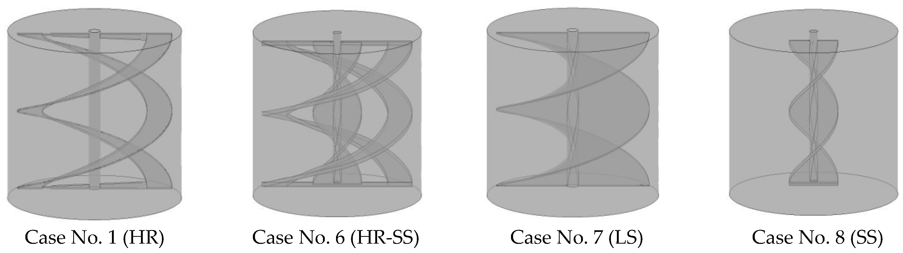
5.3. Comparison between the Helical Ribbon (HR), Small Screw (SS), Large Screw (LS), Helical Ribbon-Small Screw (HR-SS) Impellers
For a large tank filled with a highly viscous fluid, is the helical ribbon sufficient to ensure a good circulation of fluid particles in the whole vessel volume? The objective of this section is to compare the performance of four agitators (Figure 7).
From Figure 8, with a single screw (Case No. 8) rotating at low speed, the area near the vessel walls is no longer agitated. With a helical ribbon (Case No. 1), the flow velocity is low near the impeller shaft. If we place a small screw with the helical ribbon (Case No. 6), the circulation of fluid particles will be improved but with an increase in the power consumption.
The best configuration is a large helical screw with blades close to the walls of the tank (Case No. 7), since it just requires a slight increase in power compared to the Case No. 6.
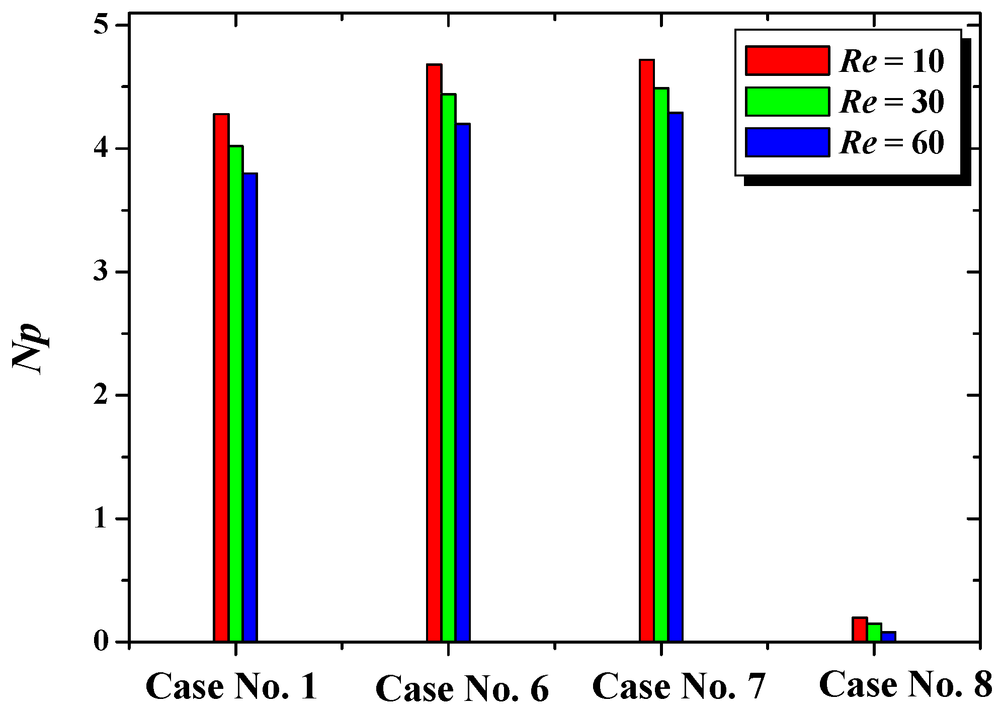
From all cases studied and at the same impeller rotational speed, Case No. 7 yields the widest well-stirred region (Figure 8). And since the size of dead zone is the lowest with this impeller design, so it may give the reduced mixing time. Also, the comparison between Case No. 6 and 7 in terms of power consumption (Np) reveals that Case No. 7 requires just a slight increase in Np (Figure 9).
6. Conclusions
The present contribution focuses on the performance of helical ribbon mixers in unbaffled stirred tanks. The problem is analyzed under numerical simulations. Visualization of the 3D flow fields and power consumption of a Newtonian fluid within the laminar regime are illustrated.
Effects of the blade diameter and the design of the lower part of impeller on the flow patterns and power input are examined. The obtained results proved the necessity of close clearance impellers for mixing highly viscous fluids at low Reynolds numbers. The shape of the lower part of impeller blade should follow the design of the tank to ensure mixing near the vessel base.
A comparison between the performance of simple helical ribbon (HR), a simple small screw (SS), helical ribbon-small screw (HR-SS) and a large screw (LS) is made. At the same impeller rotational speed, the large screw impeller yielded the widest well-stirred region, followed by the SS, HR and then by the HR-SS impeller, respectively.
In terms of less power consumption and when these impellers are rotating at the same rotational speed, the following classification is obtained: SS < HR < HR-SS < LS. Compared to the power required by small screw impellers, the increase in Np is estimated to be 31.92%, 35% and 35.5% for HR, HR-SS and LS impellers, respectively. Also, the increase in impeller rotational speed yields a decrease in power consumption, due to the decrease of viscous dissipation rates.
However, further studies are needed for other fluids and especially for rheologically complex fluids. Also, the case of unsteady flows may give further insight on the performance of these impellers, especially the mixing time at the same power input.
Author Contributions
Conceptualization, H.A. and Y.K.; Methodology, H.A. and Y.K.; Software, H.A. and Y.K.; Validation, Y.K.; Formal Analysis, H.A., Y.K. and D.S.; Investigation, H.A. and Y.K.; Resources, H.A., Y.K. and D.S.; Data Curation, H.A. and Y.K.; Writing-Original Draft Preparation, H.A. and Y.K.; Writing-Review & Editing, H.A.; Visualization, Y.K.; Supervision, H.A.; Project Administration, H.A.; Funding Acquisition, Y.K.
Conflicts of Interest
The authors declare no conflict of interest.
References
- Kuncewicz, C.; Stelmach, J. Optimization of geometric parameters of a ribbon impeller. Chem. Proc. Eng. 2017, 38, 491–502. [Google Scholar] [CrossRef] [Green Version]
- Gammoudi, A.; Ayadi, A.; Baccar, M. The hydrodynamic and thermal characterization of a yield stress fluid in stirred tanks equipped with simple helical ribbons with two stages. Meccanica 2017, 52, 1743–1766. [Google Scholar] [CrossRef]
- Mohd, S.M.; Rosfarizan, M.; Musaalbakri, A.; Arbakariya, B.A. Enhancement of red pigment production by monascuspurpureus FTC 5391 through retrofitting of helical ribbon impeller in stirred-tank fermenter. Food Bioproc. Technol. 2012, 5, 80–91. [Google Scholar]
- Yao, W.; Mishima, M.; Takahashi, K. Numerical investigation on dispersive mixing characteristics of Maxblend and double helical ribbons. Chem. Eng. J. 2001, 84, 565–571. [Google Scholar] [CrossRef]
- Ameur, H. Energy efficiency of different impellers in stirred tank reactors. Energy 2015, 93, 1980–1988. [Google Scholar] [CrossRef]
- Robinson, M.; Cleary, P.W. Flow and mixing performance in helical ribbon mixers. Chem. Eng. Sci. 2012, 84, 382–398. [Google Scholar] [CrossRef]
- Delaplace, G.; Guerin, R.; Leuliet, J.C.; Chhabra, R.P. An analytical model for the prediction of power consumption for shear thinning fluids with helical ribbon and helical screw ribbon impellers. Chem. Eng. Sci. 2006, 61, 3250–3259. [Google Scholar] [CrossRef]
- Zhang, M.; Zhang, L.; Jiang, B.; Yin, Y.; Li, X. Calculation of Metzner constant for double helical ribbon impeller by CFD method. Chin. J. Chem. Eng. 2008, 16, 686–692. [Google Scholar] [CrossRef]
- Ameur, H.; Kamla, Y.; Hadjeb, A.; Arab, I.M.; Sahel, D. Data on mixing of viscous fluids by helical screw impellers in cylindrical vessels. Data Brief 2016, 8, 220–224. [Google Scholar] [CrossRef] [PubMed]
- Ameur, H.; Kamla, Y.; Sahel, D. Performance of helical screw impellers for mixing of viscous liquids in cylindrical reactors. ChemistrySelect 2017, 2, 1891–1894. [Google Scholar] [CrossRef]
- Maingonnat, J.F.; Doublier, J.L.; Lefebvre, J.; Delaplace, G. Power consumption of a double ribbon impeller with Newtonian and shear thinning fluids and during the gelation of a iota-carrageenan solution. J. Food Eng. 2008, 87, 82–90. [Google Scholar] [CrossRef]
- Driss, Z.; Karray, S.; Kchaou, H.; Abid, M.S. CFD simulation of the laminar flow in stirred tanks generated by double helical ribbons and double helical screw ribbons impellers. Central Eur. J. Eng. 2011, 1, 413–422. [Google Scholar] [CrossRef] [Green Version]
- Ameur, H.; Bouzit, M.; Ghenaim, A. Hydrodynamics in a vessel stirred by simple and double helical ribbon impellers. Central Eur. J. Eng. 2013, 3, 87–98. [Google Scholar] [CrossRef]
- Anne-Archard, D.; Marouche, M.; Boisson, H.C. Hydrodynamics and Metzner–Otto correlation in stirred vessels for yield stress fluids. Chem. Eng. J. 2006, 125, 15–24. [Google Scholar] [CrossRef] [Green Version]
- Iranshahi, A.; Heniche, M.; Bertrand, F.; Tanguy, P.A. Numerical investigation of the mixing efficiency of the EkatoParavisc impeller. Chem. Eng. Sci. 2006, 61, 2609–2617. [Google Scholar] [CrossRef]
- Yu, L.; Ma, J.; Chen, S. Numerical simulation of mechanical mixing in high solid anaerobic digester. Bioresour. Technol. 2011, 102, 1012–1018. [Google Scholar] [CrossRef] [PubMed]
- Dieulot, J.Y.; Delaplace, G.; Guerin, R.; Brienne, J.P.; Leuliet, J.C. Laminar mixing performances of a stirred tank equipped with helical ribbon agitator subjected to steady and unsteady rotational speed. Chem. Eng. Res. Des. 2002, 80, 335–344. [Google Scholar] [CrossRef]
- Kuncewicz, C.; Szulc, K.; Kurasinski, T. Hydrodynamics of the tank with a screw impeller. Chem. Eng. Proc. 2005, 44, 766–774. [Google Scholar] [CrossRef]
- Masiuk, S.; Rakoczy, R. The entropy criterion for the homogenisation process in a multi-ribbon blender. Chem. Eng. Proc. 2006, 45, 500–506. [Google Scholar] [CrossRef]
- Rivera, C.A.; Heniche, M.; Takenaka, K.; Tanguy, P.A. Finite element modeling of the laminar and transition flow of the Super blend dual shaft coaxial mixer on parallel computers. Chem. Eng. Sci. 2009, 64, 4442–4456. [Google Scholar] [CrossRef]
- Bao, Y.; Lu, Y.; Liang, Q.; Li, L.; Gao, Z.; Huang, X.; Qin, S. Power demand and mixing performance of coaxial mixers in a stirred tank with CMC solution. Chin. J. Chem. Eng. 2015, 23, 623–632. [Google Scholar] [CrossRef]
- Gijón-Arreortúa, I.; Tecante, A. Mixing time and power consumption during blending of cohesive food powders with a horizontal helical double-ribbon impeller. J. Food Eng. 2015, 149, 144–152. [Google Scholar] [CrossRef]
- Oliva, A.M.; Hargrave, N.R.; Feys, D.; Park, J. Simulation of yield-stress fluid in a rotational rheometer: The effect of the vane geometry on cement flows. In Proceedings of the 2015 COMSOL Conference in Boston, Boston, MA, USA, 7–9 October 2015. [Google Scholar]
- Liu, B.; Wang, M.; Liu, J.L.; Qian, L.; Jin, Z. Experimental study on micromixing characteristics of novel large-double-blade impeller. Chem. Eng. Sci. 2015, 123, 641–647. [Google Scholar] [CrossRef]
- Patel, D.; Ein-Mozaffari, F.; Mehrvar, M. Using tomography to visualize the continuous-flow mixing of biopolymer solutions inside a stirred tank reactor. Chem. Eng. J. 2014, 239, 257–273. [Google Scholar] [CrossRef]
- Ameur, H. Mixing of shear thinning fluids in cylindrical tanks: Effect of the impeller blade design and operating conditions. Int. J. Chem. React. Eng. 2016, 14, 1025–1034. [Google Scholar] [CrossRef]
- Aubin, J.; Naud, I.; Xuereb, C.; Bertrand, J. Blending of Newtonian and shear-thinning fluids in a tank stirred with a helical screw agitator. Chem. Eng. Res. Des. 2000, 78, 1105–1114. [Google Scholar] [CrossRef] [Green Version]
Figure 1.
Stirred system.

Figure 2.
Meshing of the computational domain with tetrahedral elements: (a) Horizontal view; (b) Isometric View.
Figure 2.
Meshing of the computational domain with tetrahedral elements: (a) Horizontal view; (b) Isometric View.

Figure 3.
Power number for n = 0.4.

Figure 4.
Tangential velocity for Re = 10, Z* = 0.45, θ = 90°.

Figure 5.
Velocity contours for Re = 10.

Figure 6.
Velocity contours for Re = 10.

Figure 7.
Stirred system.

Figure 8.
Velocity contours Re = 100, Z* = 0.5.

Figure 9.
Power number for different cases.


Table 1.
Geometrical parameters of mixing vessels with a flat bottom vessel.
| Case | H/D | d1/D | d2/D | h1/D | h2/D | h3/D | c/D | ds/D |
|---|---|---|---|---|---|---|---|---|
| No. 1 | 1 | 0.89 | 0.89 | 0.445 | 0.445 | 0 | 0.052 | 0.033 |
| No. 2 | 1 | 0.4 | 0.89 | 0.445 | 0.445 | 0 | 0.052 | 0.033 |
| No. 3 | 1 | 0.4 | 0.89 | 0.779 | 0.111 | 0 | 0.052 | 0.033 |
Table 2.
Geometrical parameters of mixing systems with a dished bottom vessel.
| Case | H/D | d1/D | d2/D | h1/D | h2/D | h3/D | c/D | ds/D |
|---|---|---|---|---|---|---|---|---|
| No. 4 | 1 | 0.89 | 0.89 | 0.445 | 0.445 | 0.222 | 0.052 | 0.033 |
| No. 5 | 1 | 0.4 | 0.89 | 0.445 | 0.445 | 0.338 | 0.052 | 0.033 |
Table 3.
Power number for Re = 10.
| Case | No. 1 | No. 2 | No. 3 |
|---|---|---|---|
| Np | 4.28 | 3.75 | 1.79 |
Table 4.
Power number for Re = 10.
| Case | No. 4 | No. 5 |
|---|---|---|
| Np | 4.49 | 4.66 |
© 2018 by the authors. Licensee MDPI, Basel, Switzerland. This article is an open access article distributed under the terms and conditions of the Creative Commons Attribution (CC BY) license (http://creativecommons.org/licenses/by/4.0/).
Share and Cite
MDPI and ACS Style
Ameur, H.; Kamla, Y.; Sahel, D. Performance of Helical Ribbon and Screw Impellers for Mixing Viscous Fluids in Cylindrical Reactors. ChemEngineering 2018, 2, 26. https://doi.org/10.3390/chemengineering2020026
AMA Style
Ameur H, Kamla Y, Sahel D. Performance of Helical Ribbon and Screw Impellers for Mixing Viscous Fluids in Cylindrical Reactors. ChemEngineering. 2018; 2(2):26. https://doi.org/10.3390/chemengineering2020026
Chicago/Turabian StyleAmeur, Houari, Youcef Kamla, and Djamel Sahel. 2018. "Performance of Helical Ribbon and Screw Impellers for Mixing Viscous Fluids in Cylindrical Reactors" ChemEngineering 2, no. 2: 26. https://doi.org/10.3390/chemengineering2020026