
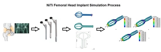
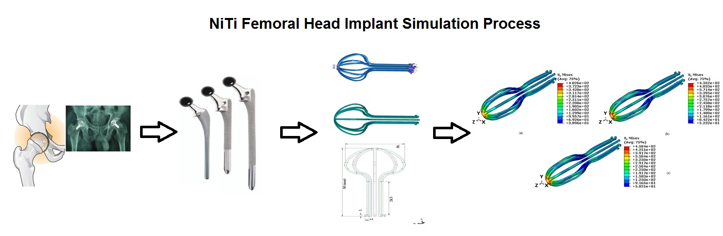
Finite Element Simulation of NiTi Umbrella-Shaped Implant Used on Femoral Head under Different Loadings


Abstract
:
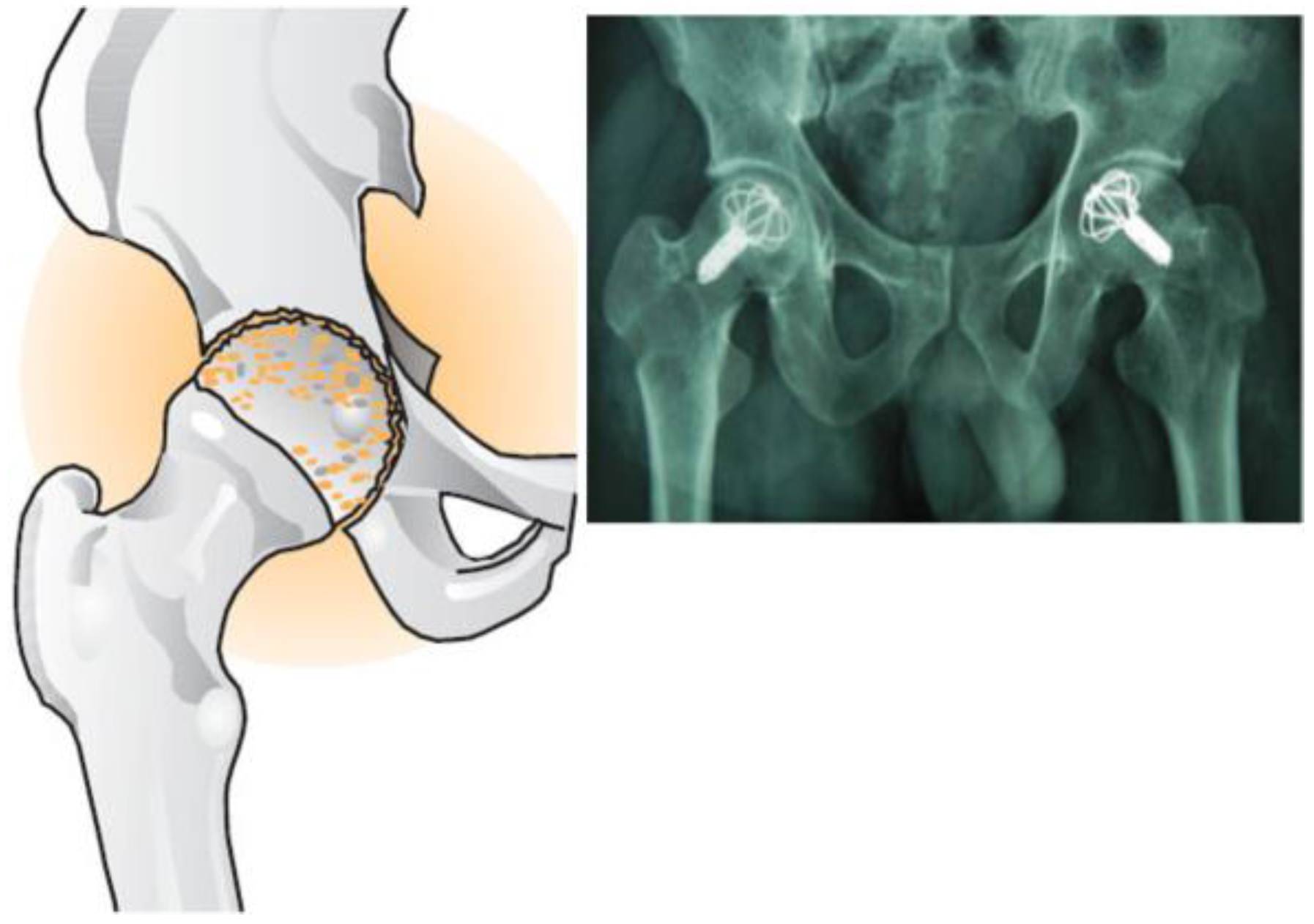
1. Introduction
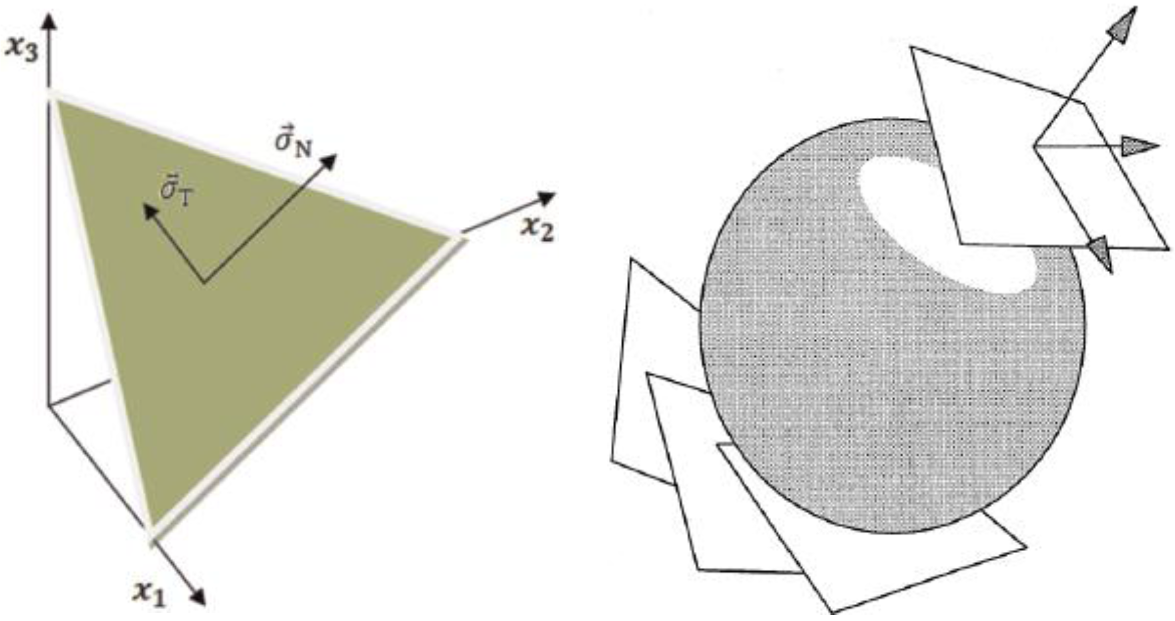
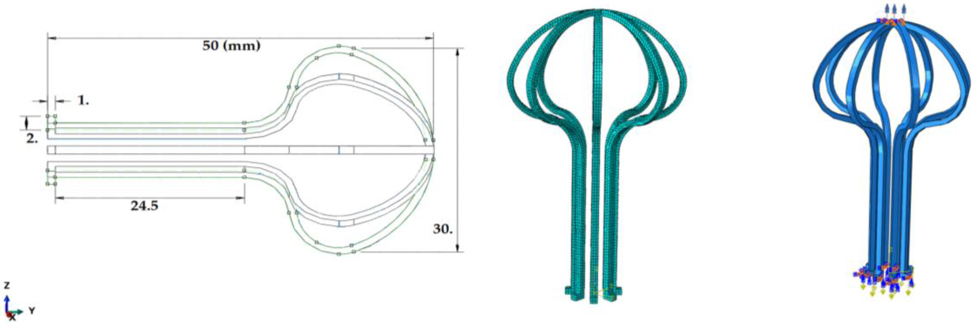
2. Modeling and Simulation
3. Results and Discussion
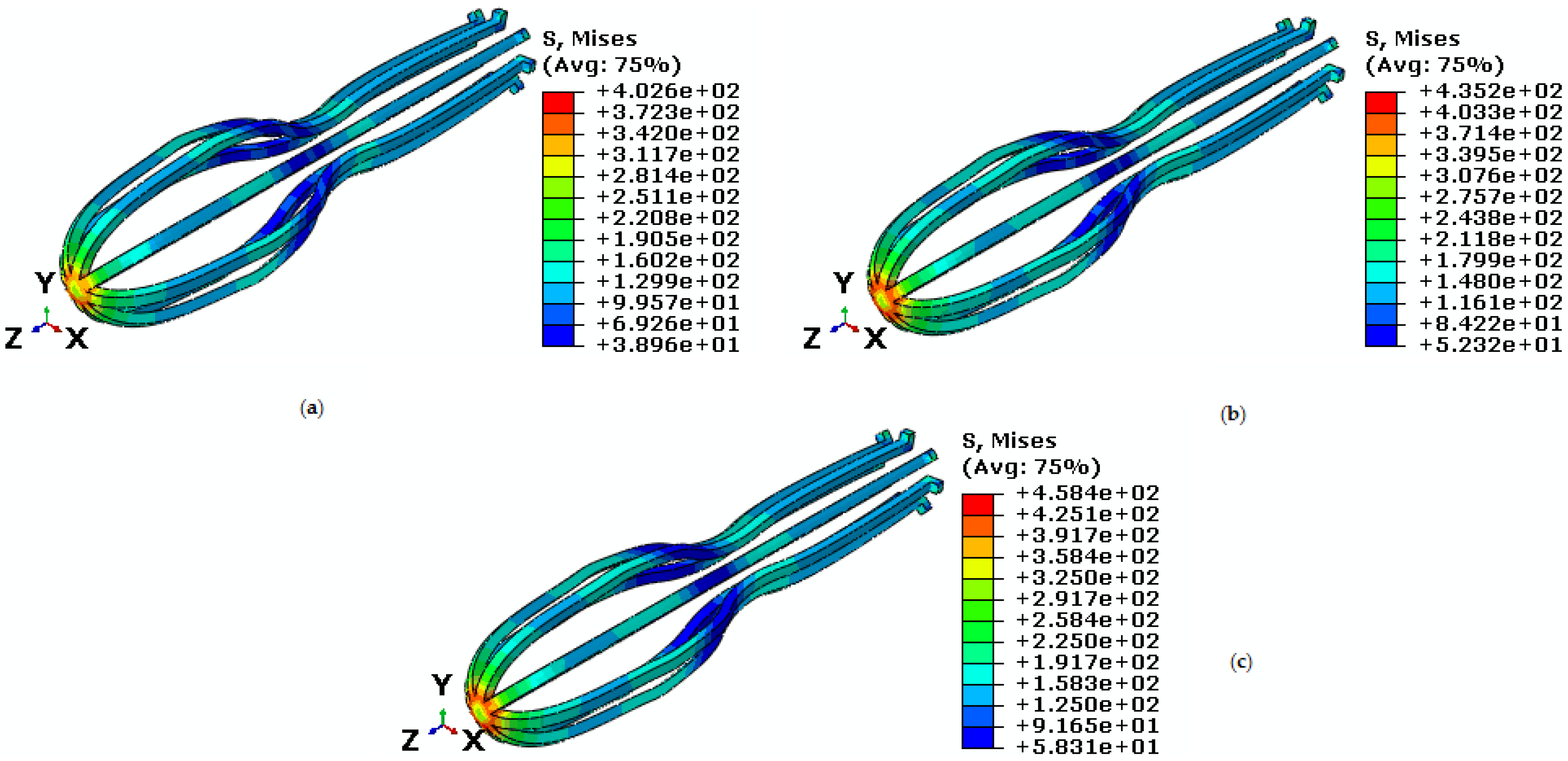
3.1. Study of the Behavior of Umbrella-Shaped Implant at Temperature Above
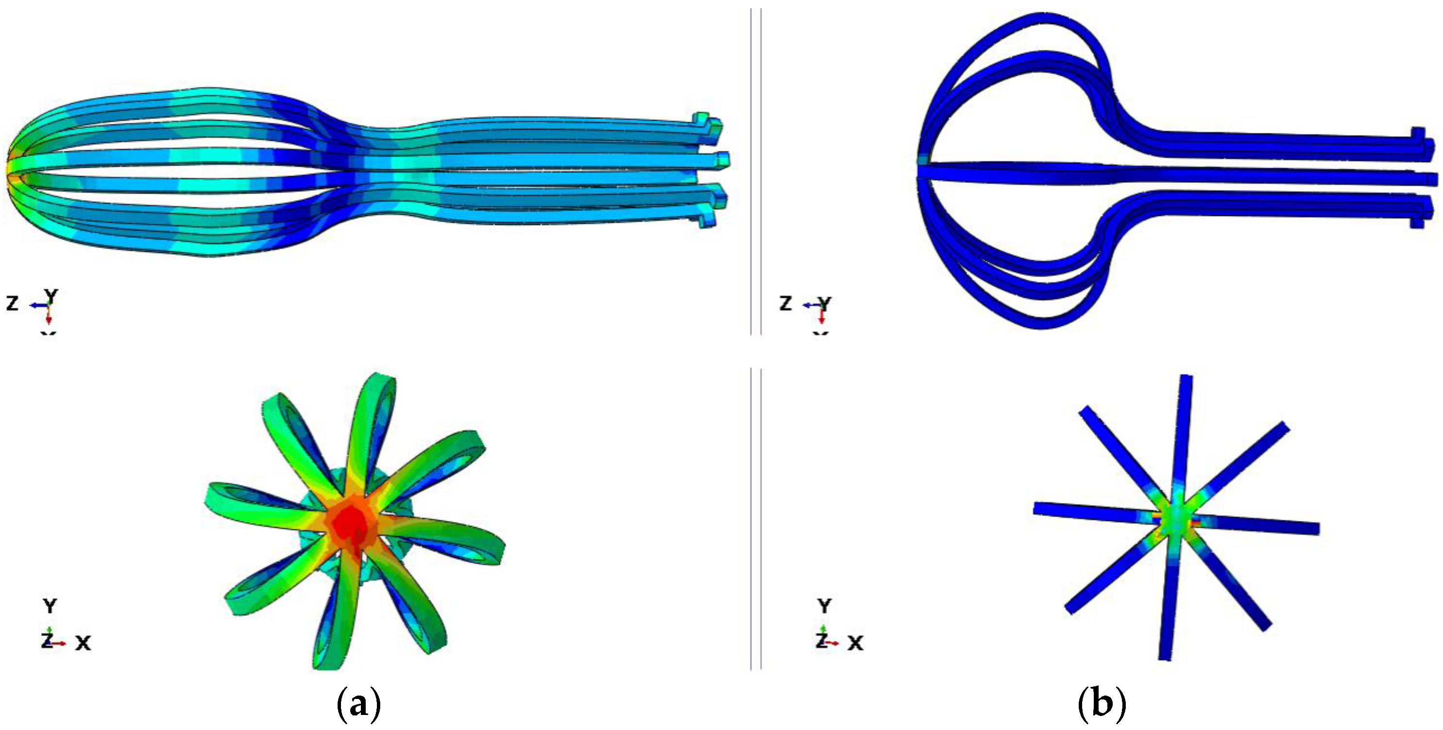
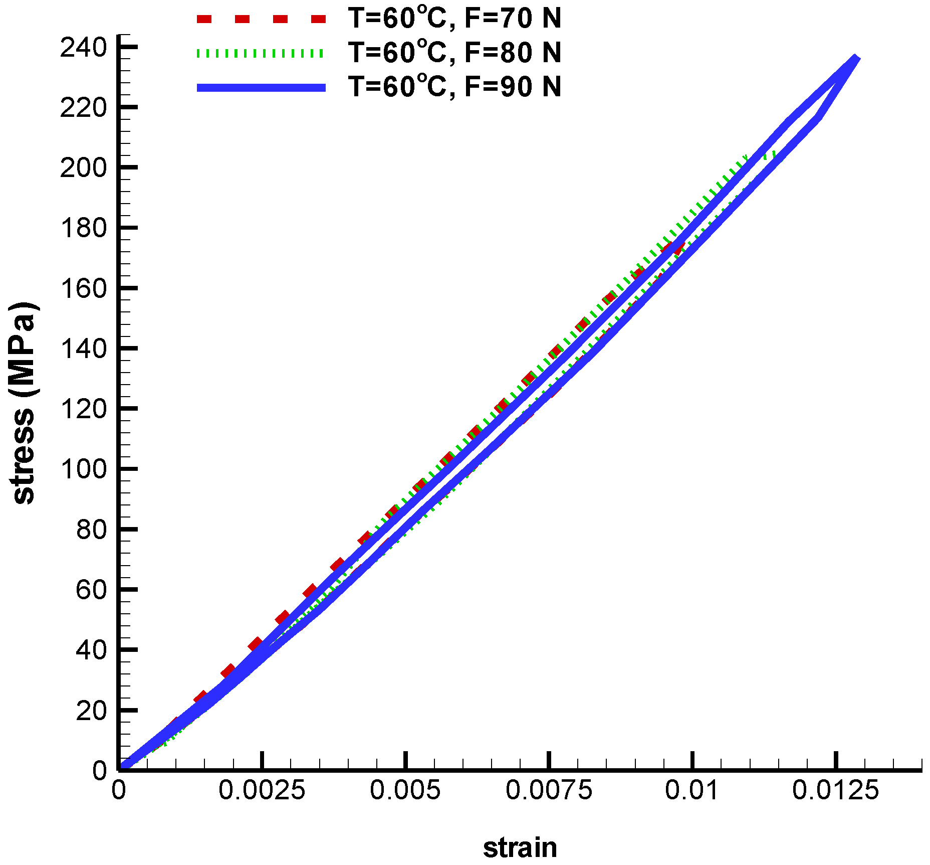
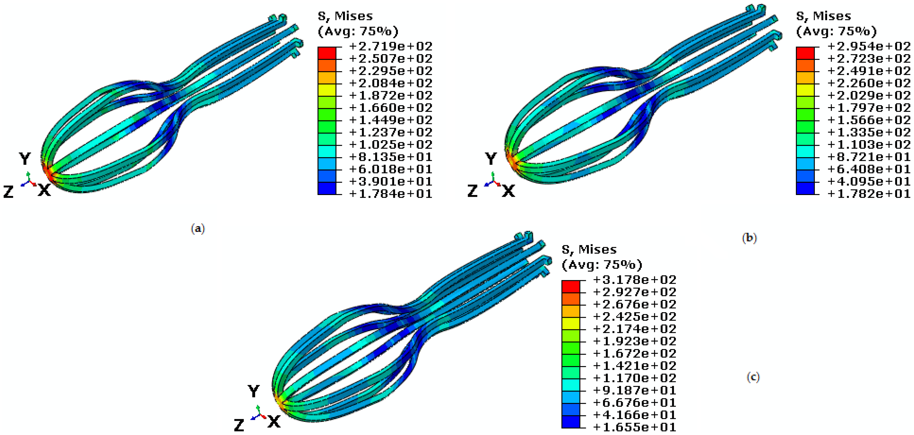
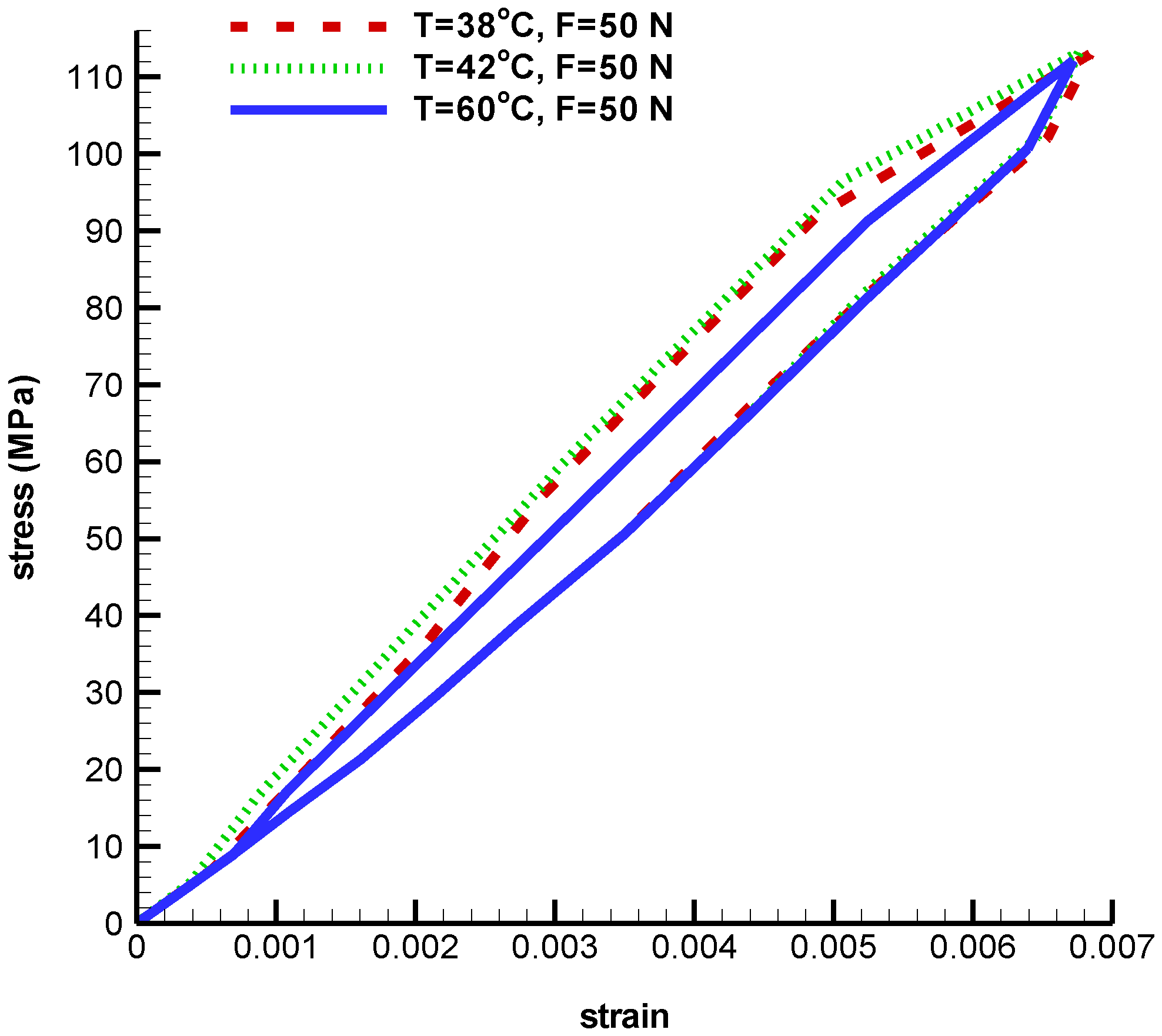
3.1.1. Pseudoelastic Behavior under Simple Tension
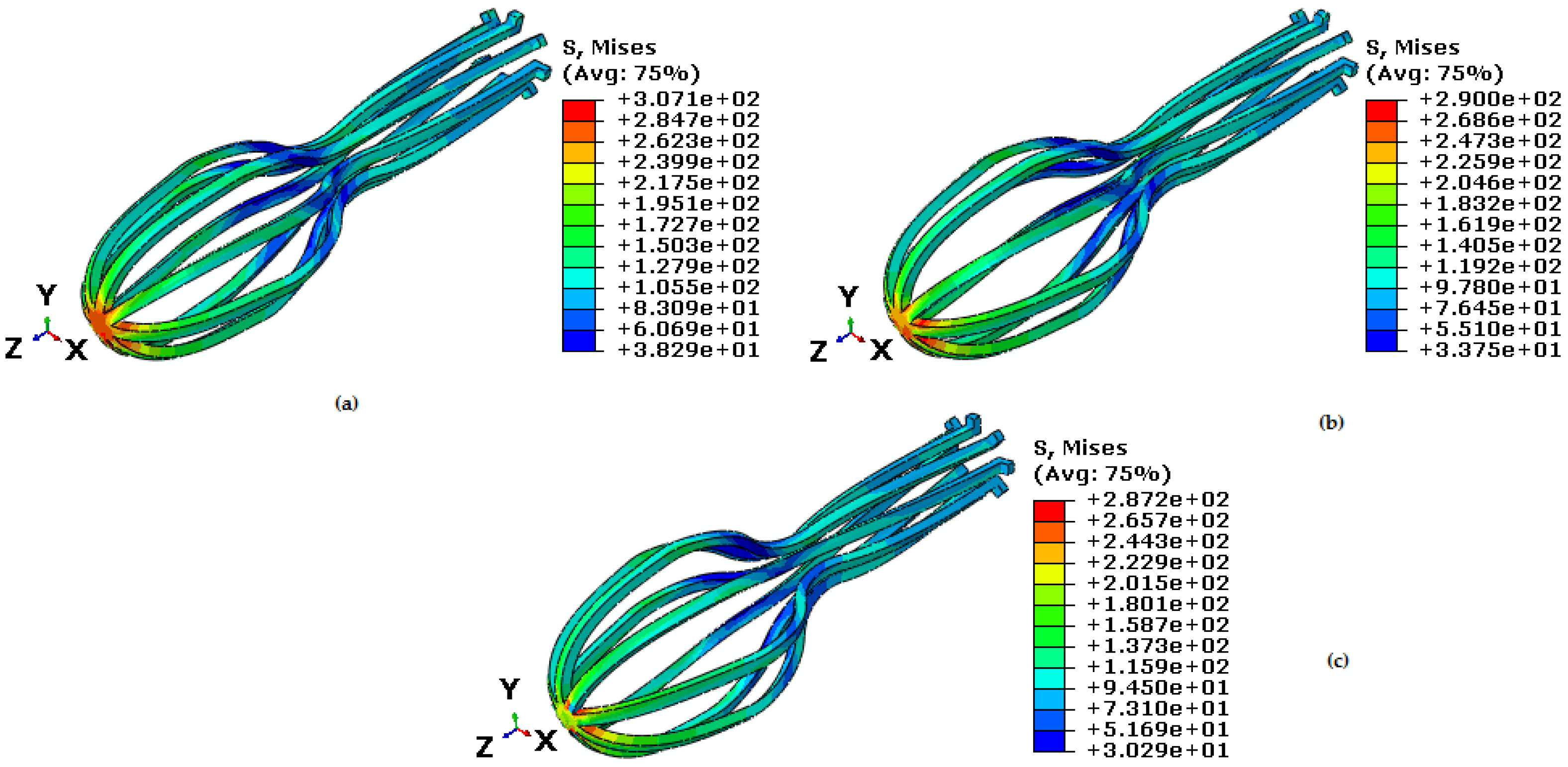
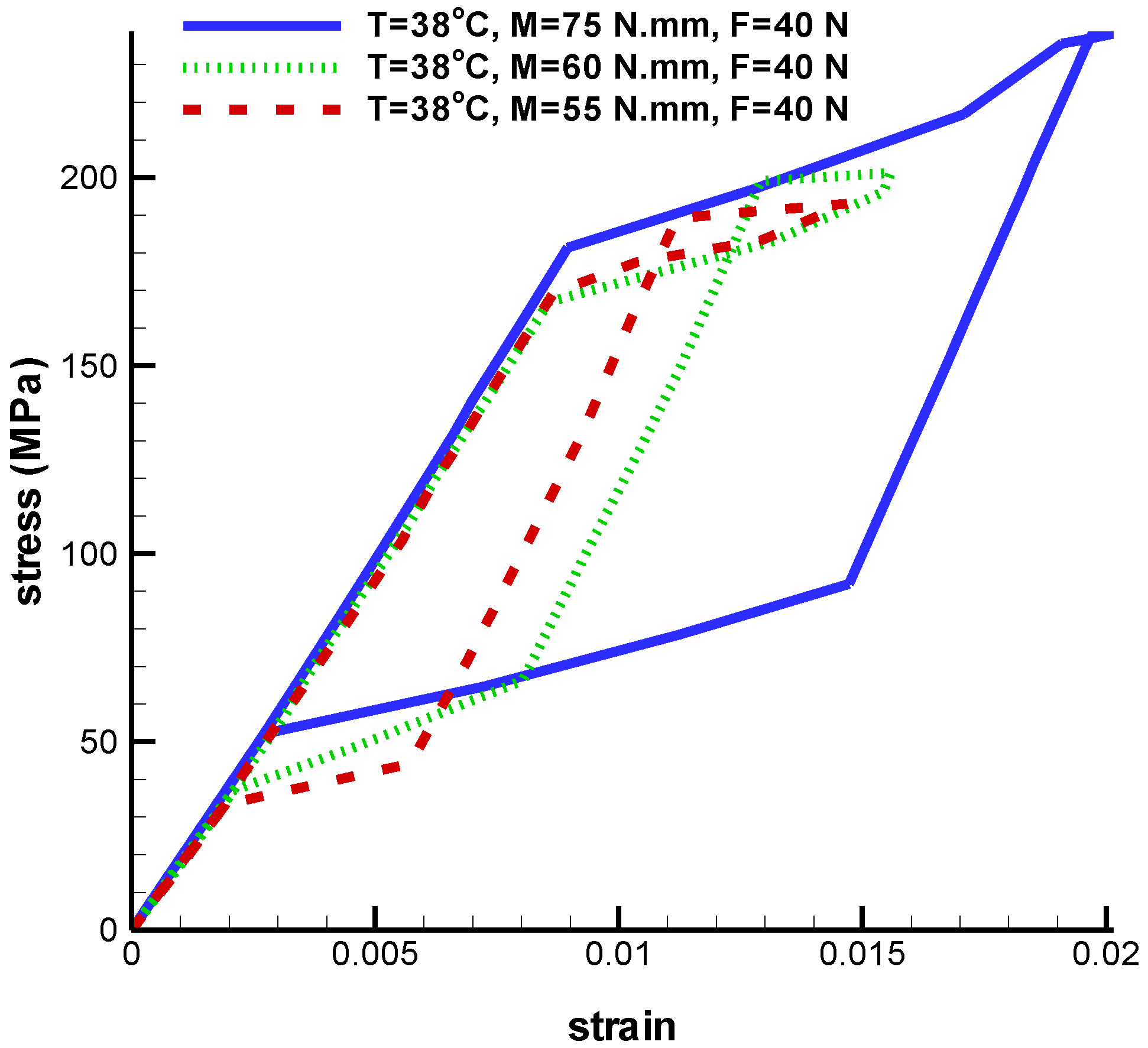
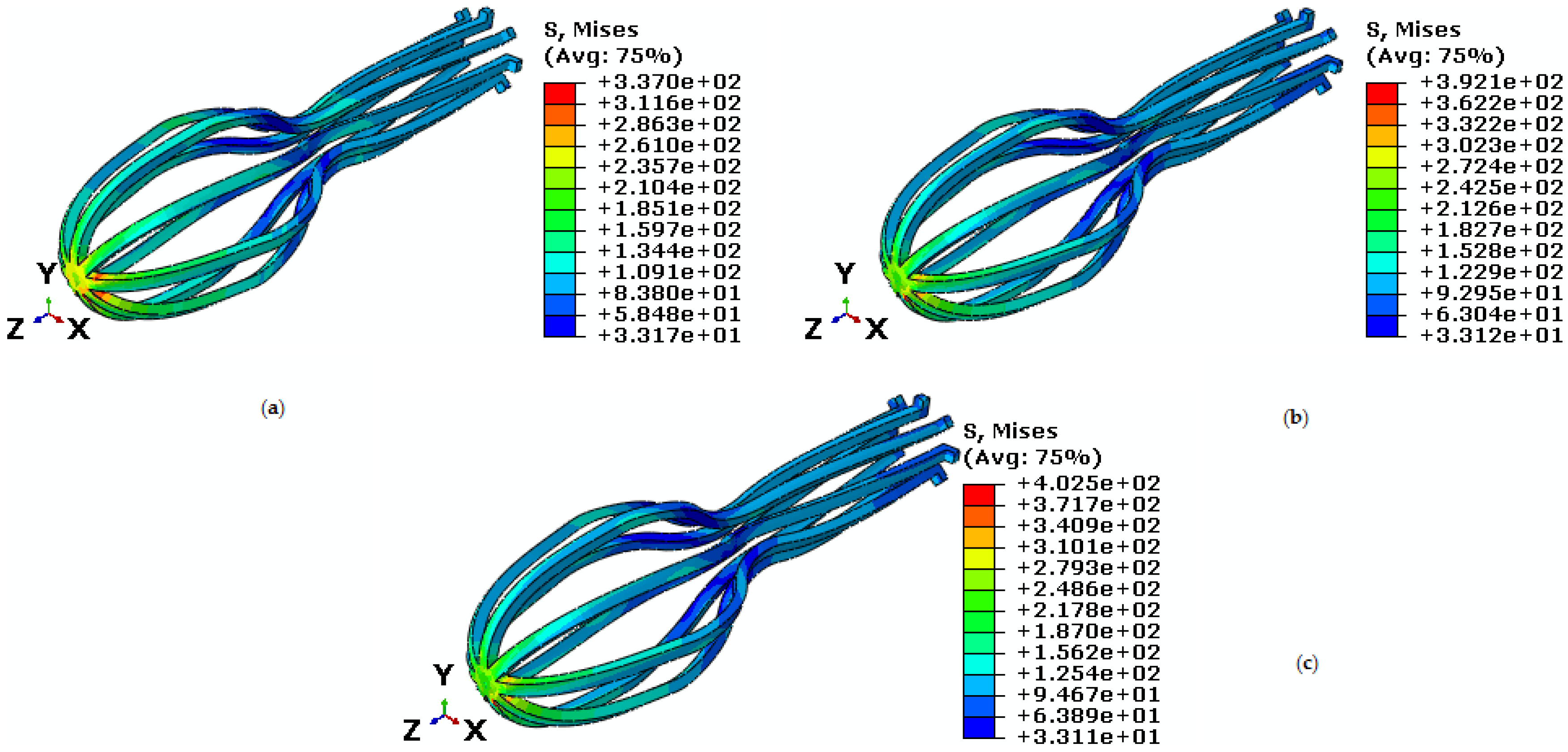
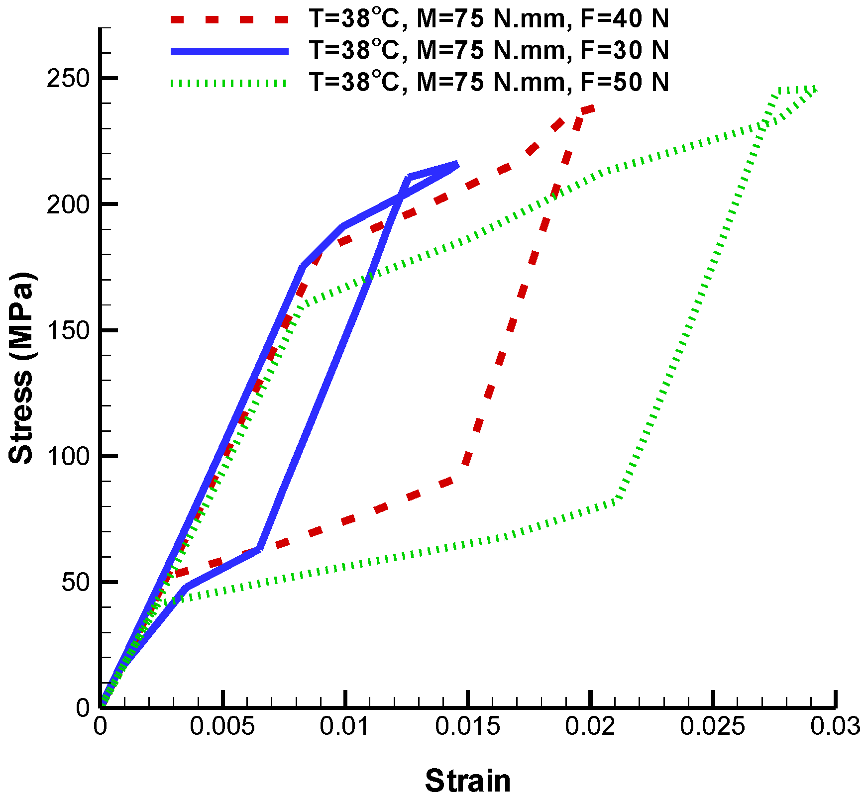
3.1.2. Pseudoelastic Behavior under Coupling Tension-Torsion
- The tensile force is variable and torsion torque is constant;
- The tensile force is constant and torsion torque is variable;
- Both tensile force and torsion torque are constant and temperature is variable.
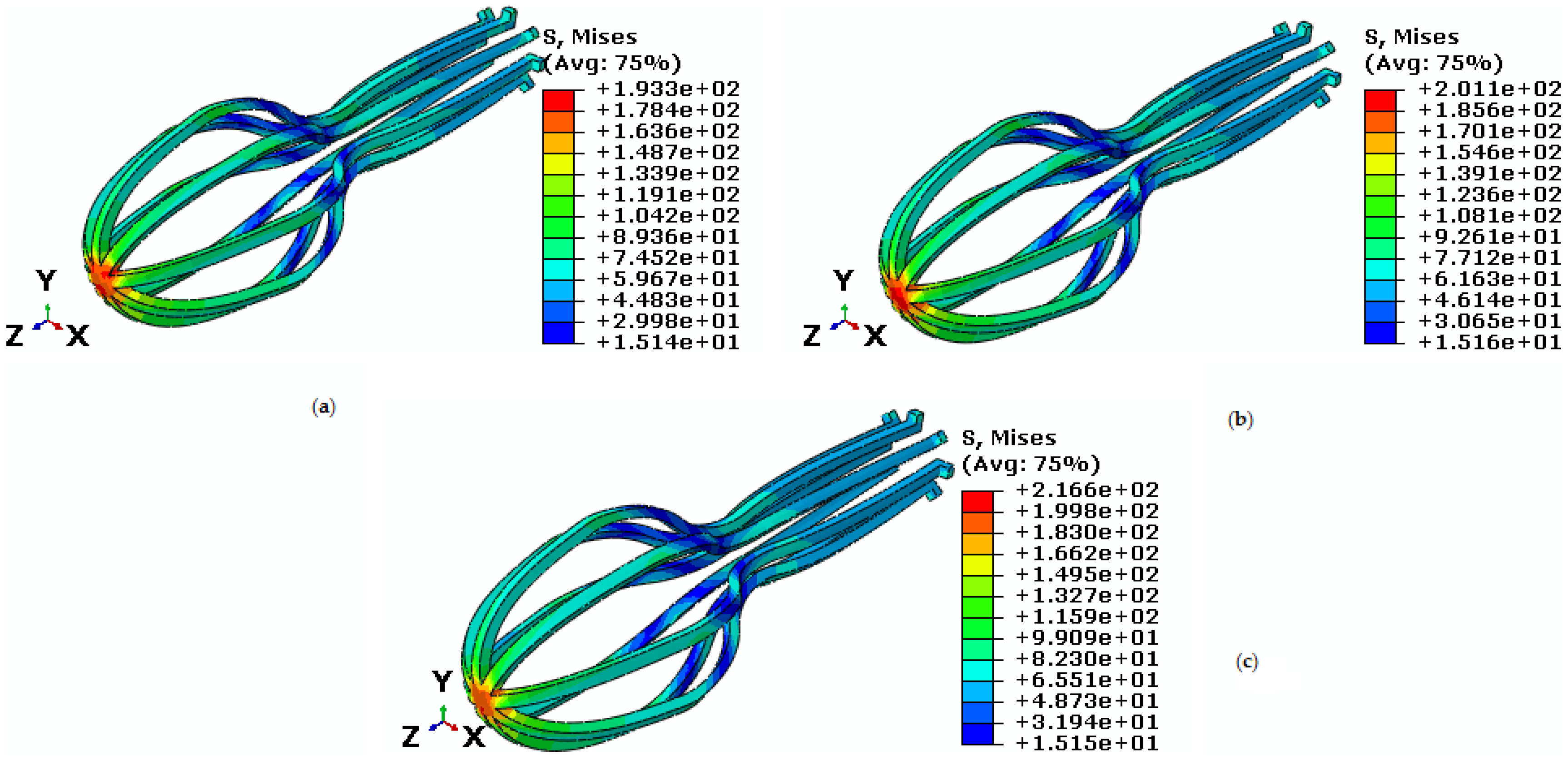
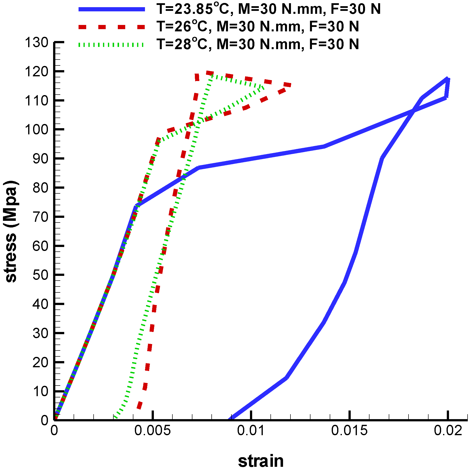
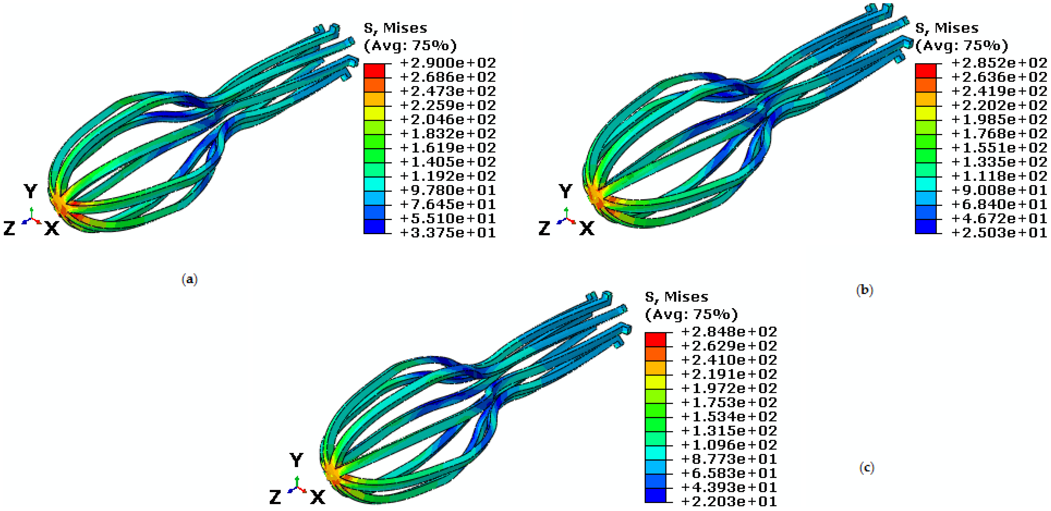
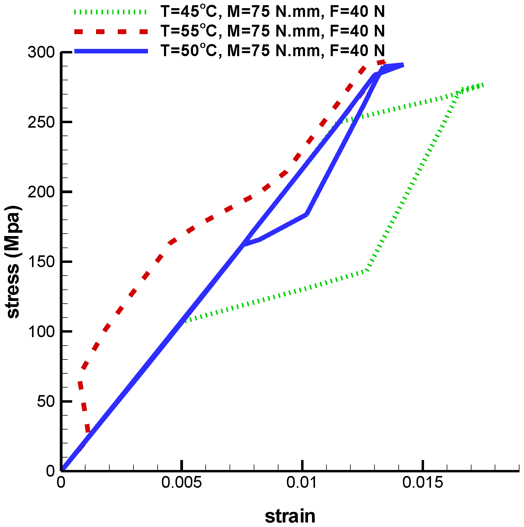
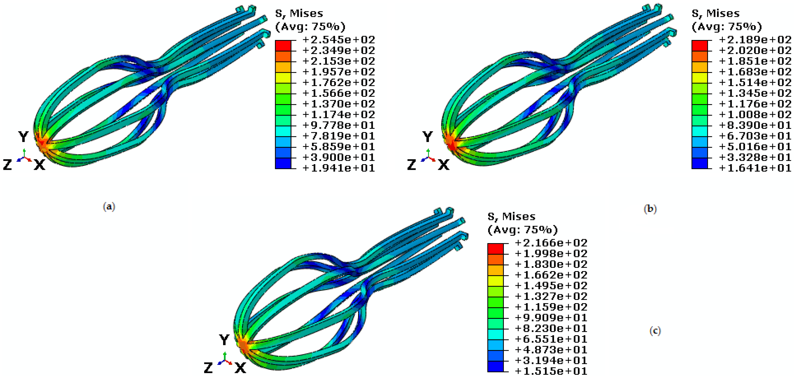
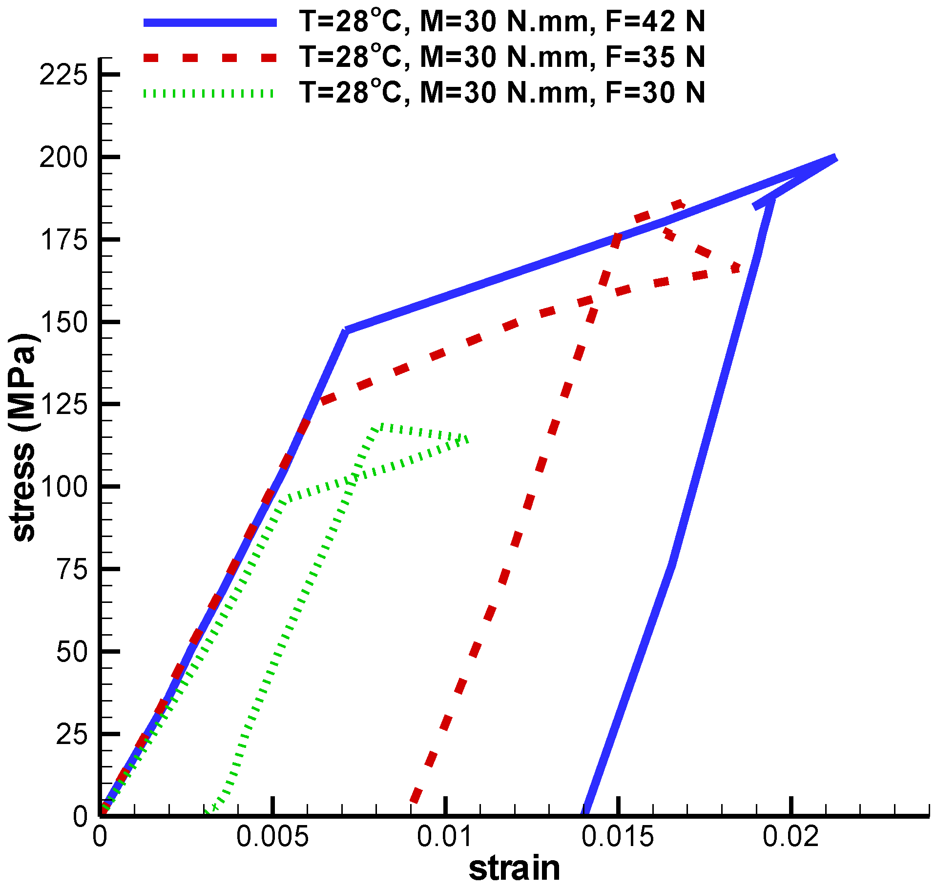
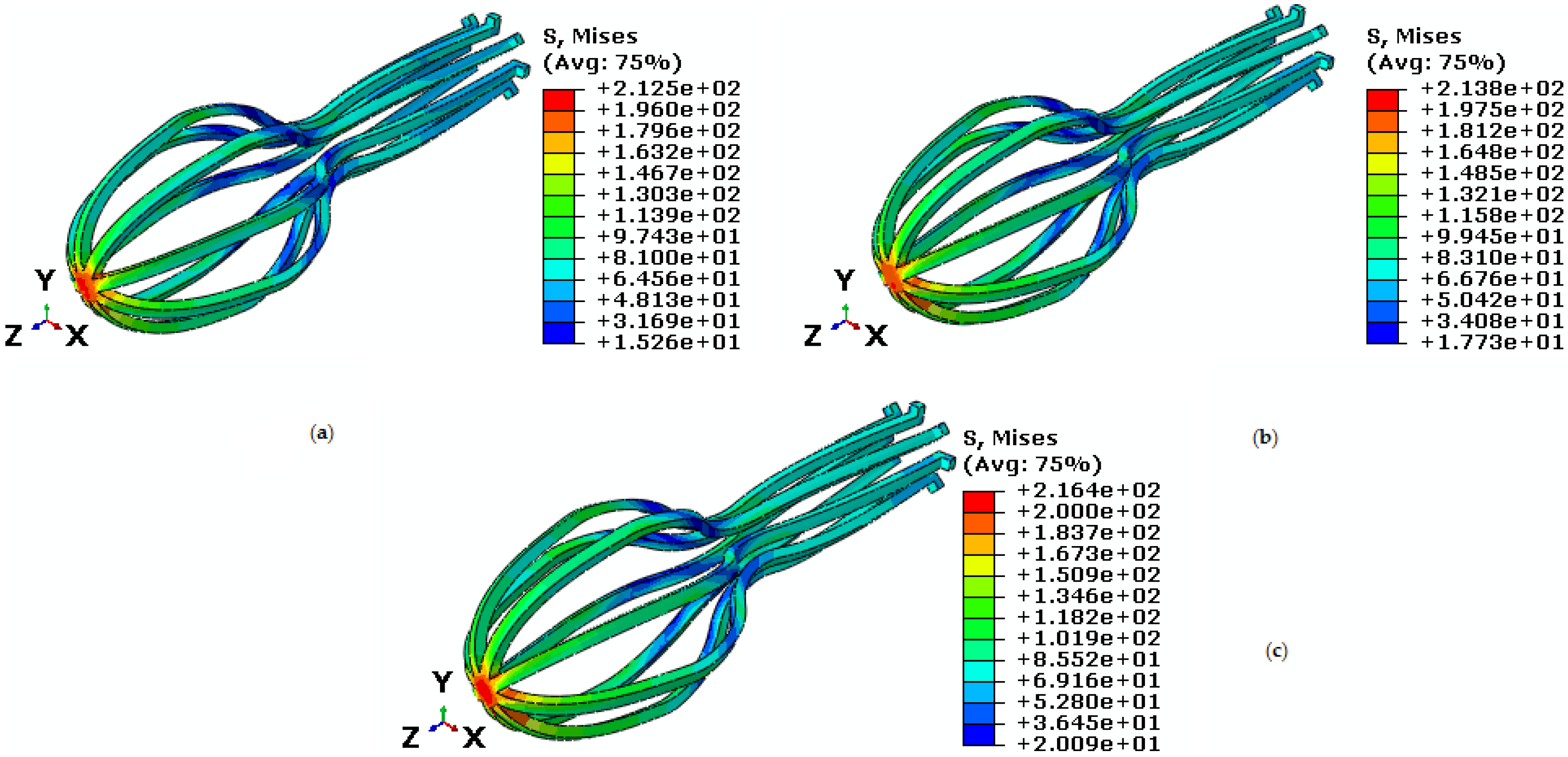
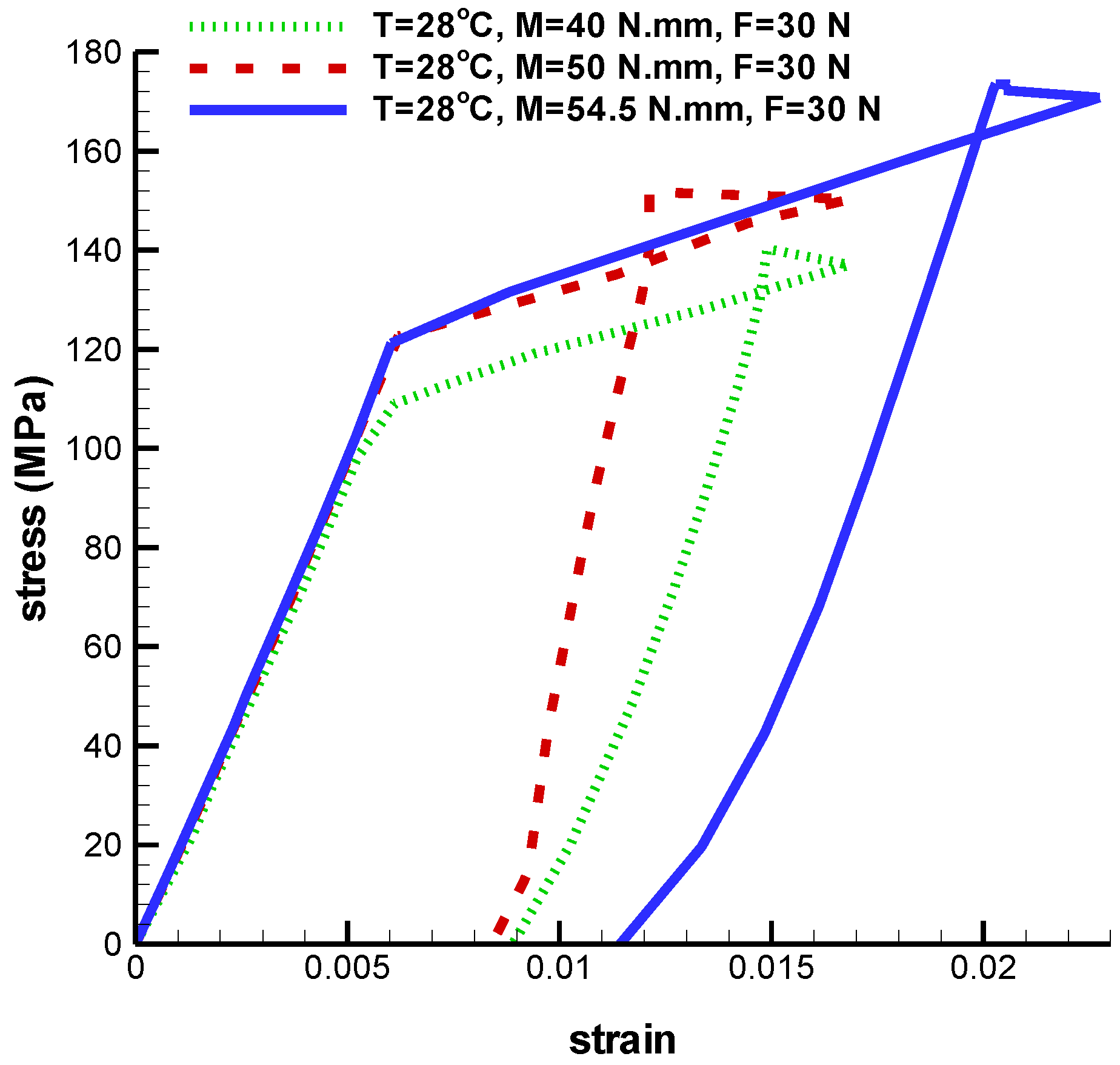
3.2. Study of the Behavior of Umbrella-Shaped Implant under Tension-Torsion Loading at Temperature under
4. Conclusions
Author Contributions
Acknowledgments
Conflicts of Interest
References
- Yu, X.; Jiang, W.; Pan, Q.; Wu, T.; Zhang, Y.; Zhou, Z.; Du, D. Umbrella-shaped, memory alloy femoral head support device for treatment of avascular osteonecrosis of the femoral head. Int. Orthop. 2013, 37, 1225–1232. [Google Scholar] [CrossRef] [PubMed]
- Christ, D.; Reese, S. A finite element model for shape memory alloys considering thermomechanical couplings at large strains. Int. J. Solids Struct. 2009, 46, 3694–3709. [Google Scholar] [CrossRef]
- Saleeb, A.; Dhakal, B.; Owusu-Danquah, J. Assessing the performance characteristics and clinical forces in simulated shape memory bone staple surgical procedure: The significance of SMA material model. Comput. Biol. Med. 2015, 62, 185–195. [Google Scholar] [CrossRef] [PubMed]
- Brown, T.D.; Way, M.E.; Ferguson, A.B. Mechanical characteristics of bone in femoral capital aseptic necrosis. Clin. Orthop. Relat. Res. 1981, 156, 240–247. [Google Scholar] [CrossRef]
- Seki, T.; Hasegawa, Y.; Masui, T.; Yamaguchi, J.; Kanoh, T.; Ishiguro, N.; Kawabe, K. Quality of life following femoral osteotomy and total hip arthroplasty for nontraumatic osteonecrosis of the femoral head. J. Orthop. Sci. 2008, 13, 116–121. [Google Scholar] [CrossRef] [PubMed]
- Floerkemeier, T.; Lutz, A.; Nackenhorst, U.; Thorey, F.; Waizy, H.; Windhagen, H.; von Lewinski, G. Core decompression and osteonecrosis intervention rod in osteonecrosis of the femoral head: Clinical outcome and finite element analysis. Int. Orthop. 2011, 35, 1461–1466. [Google Scholar] [CrossRef] [PubMed]
- Yi, W.; Tian, Q.; Dai, Z.; Liu, X. Mechanical Behaviour of Umbrella-Shaped, Ni-Ti Memory Alloy Femoral Head Support Device during Implant Operation: A Finite Element Analysis Study. PLoS ONE 2014, 9, e100765. [Google Scholar] [CrossRef] [PubMed]
- Buehler, W.; Wiley, R. Report NOLTR 61-75; US Naval Ordinance Laboratory: Silver Spring, MD, USA, 1961. [Google Scholar]
- Liang, C.; Rogers, C.A. One-dimensional thermomechanical constitutive relations for shape memory materials. J. Intell. Mater. Syst. Struct. 1990, 1, 207–234. [Google Scholar] [CrossRef]
- Brinson, L.C. One-dimensional constitutive behavior of shape memory alloys: Thermomechanical derivation with non-constant material functions and redefined martensite internal variable. J. Intell. Mater. Syst. Struct. 1993, 4, 229–242. [Google Scholar] [CrossRef]
- Brinson, L.; Huang, M. Simplifications and comparisons of shape memory alloy constitutive models. J. Intell. Mater. Syst. Struct. 1996, 7, 108–114. [Google Scholar] [CrossRef]
- Auricchio, F.; Taylor, R.L. Shape-memory alloys: Modelling and numerical simulations of the finite-strain superelastic behavior. Comput. Methods Appl. Mech. Eng. 1997, 143, 175–194. [Google Scholar] [CrossRef]
- Boyd, J.G.; Lagoudas, D.C. A thermodynamical constitutive model for shape memory materials. Part I. The monolithic shape memory alloy. Int. J. Plast. 1996, 12, 805–842. [Google Scholar] [CrossRef]
- Lim, T.J.; McDowell, D.L. Mechanical behavior of an Ni-Ti shape memory alloy under axial-torsional proportional and nonproportional loading. J. Eng. Mater. Technol. 1999, 121, 9–18. [Google Scholar] [CrossRef]
- Mehrabi, R.; Kadkhodaei, M. 3D phenomenological constitutive modeling of shape memory alloys based on microplane theory. Smart Mater. Struct. 2013, 22, 025017. [Google Scholar] [CrossRef]
- Mehrabi, R.; Kadkhodaei, M.; Elahinia, M. Constitutive modeling of tension-torsion coupling and tension-compression asymmetry in NiTi shape memory alloys. Smart Mater. Struct. 2014, 23, 075021. [Google Scholar] [CrossRef]
- Mehrabi, R.; Kadkhodaei, M.; Andani, M.T.; Elahinia, M. Microplane modeling of shape memory alloy tubes under tension, torsion, and proportional tension–torsion loading. J. Intell. Mater. Syst. Struct. 2015, 26, 144–155. [Google Scholar] [CrossRef]
- Mehrabi, R.; Andani, M.T.; Elahinia, M.; Kadkhodaei, M. Anisotropic behavior of superelastic NiTi shape memory alloys; an experimental investigation and constitutive modeling. Mech. Mater. 2014, 77, 110–124. [Google Scholar] [CrossRef]
- Bažant, P.; Oh, B. Efficient numerical integration on the surface of a sphere. ZAMM J. Appl. Math. Mech./Z. Angew. Math. Mech. 1981, 66, 37–49. [Google Scholar] [CrossRef]


| Mechanical Properties | Value | Unite |
|---|---|---|
| 26,300 | MPa | |
| 63,000 | MPa | |
| 9 | ||
| 18.4 | ||
| 29.3 | ||
| 37 | ||
| 8 | MPa/ | |
| 13.8 | MPa/ | |
| 100 | MPa | |
| 170 | MPa | |
| 0.067 | - |
| Force (N) | Temperature () | Von-Mises Maximum Stress (MPa) | Maximum Principal Strain |
|---|---|---|---|
| 70 | 60 | 402.6 | 0.009 |
| 80 | 60 | 435.2 | 0.011 |
| 90 | 60 | 458.4 | 0.012 |
| 50 | 38 | 271.9 | 0.00683 |
| 50 | 42 | 295.4 | 0.00676 |
| 50 | 60 | 317.8 | 0.00671 |
| Force (N) | Torque (N·mm) | Temperature () | Von-Mises Maximum Stress (MPa) | Maximum Principal Strain |
|---|---|---|---|---|
| 30 | 75 | 38 | 287.2 | 0.014 |
| 40 | 75 | 38 | 290 | 0.020 |
| 50 | 75 | 38 | 307.1 | 0.029 |
| 40 | 75 | 38 | 290 | 0.020 |
| 40 | 60 | 38 | 285.2 | 0.015 |
| 40 | 55 | 38 | 284.8 | 0.014 |
| 40 | 75 | 45 | 337 | 0.017 |
| 40 | 75 | 50 | 392.1 | 0.014 |
| 40 | 75 | 55 | 402.5 | 0.013 |
| Force (N) | Torque (N·mm) | Temperature () | Von-Mises Maximum Stress (MPa) | Maximum Principle Strain |
|---|---|---|---|---|
| 42 | 30 | 28 | 254.5 | 0.021 |
| 35 | 30 | 28 | 218.9 | 0.018 |
| 30 | 30 | 28 | 216.6 | 0.010 |
| 30 | 40 | 28 | 212.5 | 0.01682 |
| 30 | 50 | 28 | 213.8 | 0.01687 |
| 30 | 54.5 | 28 | 216.4 | 0.022 |
| 30 | 30 | 23.85 | 193.3 | 0.020 |
| 30 | 30 | 26 | 201.1 | 0.012 |
| 30 | 30 | 28 | 216.6 | 0.010 |
© 2017 by the authors. Licensee MDPI, Basel, Switzerland. This article is an open access article distributed under the terms and conditions of the Creative Commons Attribution (CC BY) license ( http://creativecommons.org/licenses/by/4.0/).
Share and Cite
Mehrabi, R.; Dorri, M.; Elahinia, M. Finite Element Simulation of NiTi Umbrella-Shaped Implant Used on Femoral Head under Different Loadings. Bioengineering 2017, 4, 23. https://doi.org/10.3390/bioengineering4010023
Mehrabi R, Dorri M, Elahinia M. Finite Element Simulation of NiTi Umbrella-Shaped Implant Used on Femoral Head under Different Loadings. Bioengineering. 2017; 4(1):23. https://doi.org/10.3390/bioengineering4010023
Chicago/Turabian StyleMehrabi, Reza, Milad Dorri, and Mohammad Elahinia. 2017. "Finite Element Simulation of NiTi Umbrella-Shaped Implant Used on Femoral Head under Different Loadings" Bioengineering 4, no. 1: 23. https://doi.org/10.3390/bioengineering4010023